Assignment 17: Applications and Implications
What will it do?
The project is a WiRain Cover designed for a high-level window at the Fab Lab in Vigyan Ashram.
It will:
- Prevent rainwater from entering the lab through the window edges.
- Use a plastic cover attached to a sliding mechanism mounted outside the window.
- Be manually controlled using push buttons.
- Also be remotely controlled via Wi-Fi using a web interface or app.
- Allow users to open or close the cover depending on the weather (especially during rain).
The WiRain Cover project is a smart, automated sliding rain protection system designed specifically for high-elevation windows—such as the one at the Fab Lab in Vigyan Ashram, where rainwater enters through the edges even when the window is closed.
This system serves as an external sliding cover, made from a durable plastic sheet mounted on a rail-based sliding mechanism. The primary goal is to prevent rainwater intrusion, ensuring the safety of equipment, materials, and the comfort of people inside the lab.
The WiRain Cover has dual control modes:
Manual control through a set of push buttons, enabling local operation even without internet.
Remote control via Wi-Fi, allowing the user to open or close the sliding cover through a web interface or mobile application.
The cover can be deployed when it starts raining, and retracted after the rain stops, helping maintain airflow and visibility during normal conditions. The system can also be enhanced with future upgrades, such as automatic rain detection or integration into a smart building management system.
This project not only solves a real-world problem but also demonstrates the use of mechanical design, embedded systems, wireless communication, and user interface development in a compact, practical application.
2. Who's done what beforehand?
Automated window shutters and motorized curtain systems exist commercially.
- People have developed IoT-based window or roof covers for greenhouses and smart homes.
- Similar sliding mechanisms are used in garage doors, industrial covers, and rain-sensing systems.
- However, your project is customized for your Fab Lab’s architecture and specific rain problem, which makes it unique in context and implementation.
References: Reference1,Reference2

References: Reference
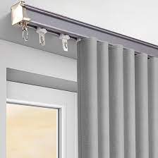
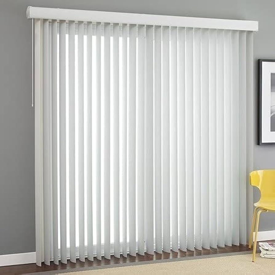
I looked at various online resources and found that the item is described as an "indoor curtain." It is primarily used for privacy or decoration inside the home, not for stopping rainwater. Therefore, it is not suitable for outdoor or waterproof purposes.
3. What sources will you use?
I referred to various sources to support the development of this project. I studied documentation from Fab Academy, especially the weeks related to mechanical design, networking, and interface development. I also searched online to identify suitable motors and controllers that can be used to control the sliding mechanism. For additional guidance, I used resources like Arduino forums, GitHub projects, and YouTube tutorials related to similar sliding systems. To refine the mechanical part of the project, I took help from mentors and colleagues at Vigyan Ashram. For the physical construction, I am using ready-made rollers and rods, which I purchased from the local market.
4. What will you design?
I will not be designing the entire rod and roller system from scratch because 3D printing such parts would take a lot of time and may not be cost-effective. Instead, I purchased ready-made rollers and aluminum rods from the market, which are not only easily available but also more affordable than custom 3D-printed parts.
However, I will be designing the following components based on my project requirements:
- A sliding frame mechanism to hold and move the plastic cover smoothly along the window.
- A motor mount and gear/pulley system to control the sliding action of the cover.
- Custom parts for holding the motor in place and for adjusting the belt tension as needed.
- A control circuit using an ESP32 microcontroller, capable of handling both manual and Wi-Fi-based control.
- A push-button interface for local, manual operation.
- A web-based user interface to allow remote control via Wi-Fi using a smartphone or computer.
- These designs will be tailored to fit the dimensions and functional needs of the Fab Lab's window setup.
5. What materials and components will be used?
The following materials and components will be used in the construction of the WiRain Cover project:
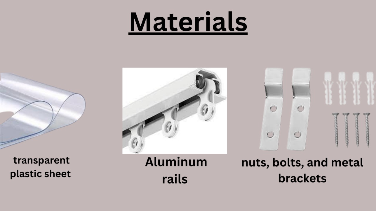
Materials:
- A transparent plastic sheet will be used as the main rain cover, allowing light to pass while protecting against water.
- Aluminum rails will serve as the sliding track for the cover.
- Plywood sheets will be used for the supporting structure and to mount various components.
- Fasteners, such as nuts, bolts, and metal brackets, will be used for assembling the frame and securing all parts.
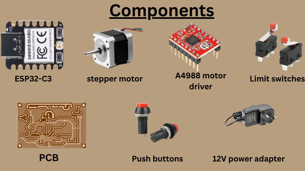
Electronic Components:
- An ESP32-C3 microcontroller will be used for Wi-Fi connectivity and overall control of the system.
- A stepper motor will drive the sliding mechanism.
- An A4988 motor driver will control the stepper motor.
- Limit switches will detect the open and closed positions of the cover to prevent over-travel.
- Push buttons will provide a manual control option for local operation.
- A 12V power adapter will supply power to the motor and control system.
- Wires, connectors, and a custom PCB will be used to interconnect all electronic components.
These materials and components are selected based on availability, cost-effectiveness, and compatibility with the requirements of the system.
6. Where will they come from?
Most of the required electronic components such as the ESP32-C3 microcontroller, stepper motor, motor driver (A4988), limit switches, and push buttons will be sourced from the Fab Lab inventory if available. If not, they will be purchased from local electronics shops or online platforms such as Robu.in, Amazon, or ElectronicsComp.com.
The mechanical parts including the transparent plastic sheet, aluminum rails, and mounting brackets will be sourced from local hardware stores near Vigyan Ashram. These materials are generally available in construction or building material shops and are cost-effective when bought locally.
For the fabrication of custom parts like motor holders, belt tensioners, and support mounts, I will use the digital fabrication tools available in the Fab Lab. This includes the laser cutter for plywood parts, the 3D printer for custom plastic components, and the CNC machine if any precise mechanical structure is needed.
Standard items such as nuts, bolts, screws, and plywood for structural support are readily available in the Vigyan Ashram workshop itself, minimizing the need for external purchases.
By combining locally purchased items, reused Fab Lab materials, and digital fabrication, the sourcing strategy is both cost-effective and efficient, supporting rapid prototyping and iteration.
7. How much will they cost?
Estimated Bill of Materials (BOM)
| Item | Qty | Cost (INR) |
|---|---|---|
| ESP32-C3 | 1 | ₹300 |
| Stepper Motor | 1 | ₹250 |
| Motor Driver A4988 | 1 | ₹150 |
| Plastic transparent Cover | 1 | ₹200 |
| Push Buttons | 2 | ₹40 |
| Limit Switches | 2 | ₹60 |
| Aluminum rails | 1 | ₹500 |
| Power Adapter | 1 | ₹150 |
| pcb | 1 | ₹100 |
| 10M GT2 Width 6mm White Open Timing Belt | 1 | ₹300 | Misc (wires, nuts, etc.) | nun | ₹100 |
Total Cost: ₹2150
8. What parts and systems will be made?
- A custom sliding mechanism moving rail
- Motor mount and pulley system
- Control system circuit (push buttons + ESP32)
- Web-based control interface
- Basic enclosure or weather cover for the electronics
9. What processes will be used?
structural components, 2D design and laser cutting will be employed to create precise parts from materials like acrylic or plywood. 3D printing will be used to fabricate custom components such as motor mounts, brackets, and spacers that are difficult to find or customize through other means. Electronics development will begin with basic circuit prototyping on a breadboard, followed by either a soldered circuit or a simple custom-designed PCB, depending on time and complexity. Soldering and wiring will be essential to connect all components, including motors, buttons, and the ESP32 controller. Programming the ESP32 will be done using the Arduino IDE with C++ to enable both manual and Wi-Fi-based control. For the user interface, a Telegram bor will be developed to allow remote access to the system. Mechanical processes such as drilling, fitting, and assembling the rails, motor, pulley, and plastic cover will also be necessary to bring all the components together. These combined processes will ensure both the physical and functional reliability of the final system.
10. What questions need to be answered?
- What is the best mechanism to slide the cover smoothly?
- Should you use a DC motor or stepper motor? Which gives better control?
- How to secure the mechanism outside safely and reliably?
- How to weatherproof the electronics?
- Can the cover be opened/closed automatically using a rain sensor in the future?
- How to ensure safety when operating manually or remotely?
11. How will it be evaluated?
- Does the system successfully slide the cover open and closed?
- Is it manually operable using push buttons?
- Does the Wi-Fi control work reliably?
- Does it effectively reduce rainwater entry into the Fab Lab?
- Is the mechanism strong, smooth, and safe?
- Are the electronics and structure neatly integrated?
- Is the design scalable or reusable for similar applications?
12. What tasks have been completed, and what tasks remain?
Completed Task :
1. Materials Selection
2. PCB design using KiCad
3. PCB milling using SRM-20
4. Electronics soldering
5. Hardware connections and functionality checks
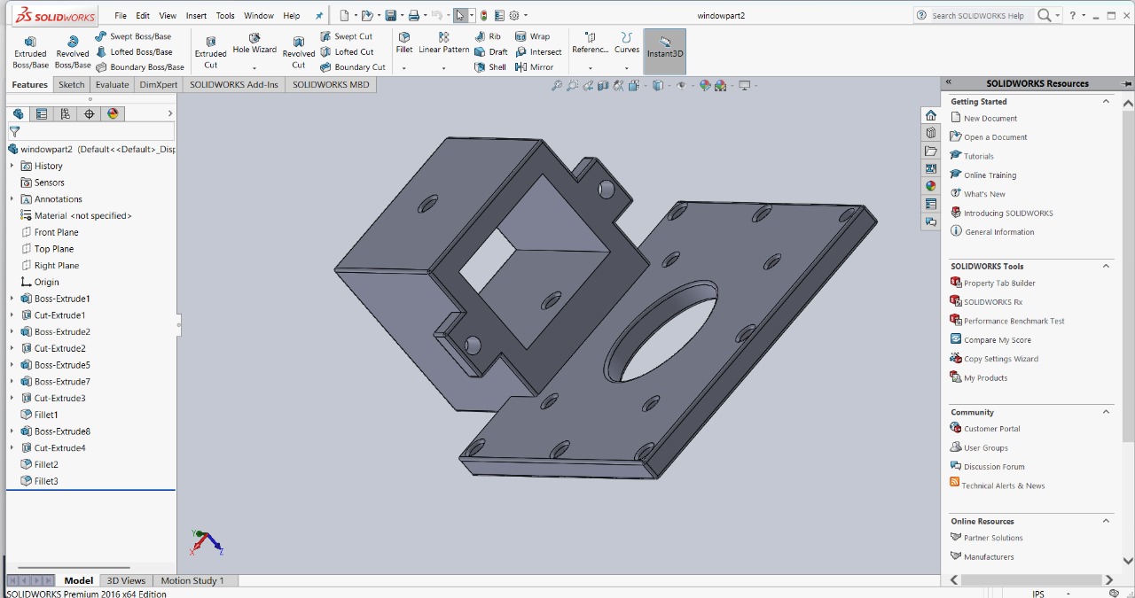
6. 3D design
7. 2D design
8. 2D design cutting using a laser cutter
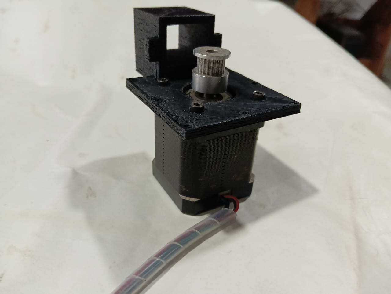
9. Hardware assembly into the 3D structure
10. mechanism installation
11. Programming and initial testing of the system
12. Final testing of the complete project
Remaining Task :
vinyl cutting for the manual control box
13. What's working? what's not?
In my final project, the stepper motor used for the sliding mechanism is working well. I have implemented two operating modes—manual control and cloud-based control using the Blynk app—both of which are functioning properly. For the electronics, I’m using an ESP32-C3 controller and an A4988 driver to control the stepper motor, and the overall communication and operation are stable. So far, both the mechanical system and communication setup are working as expected. There are no major issues at this stage.
14. What questions need to be resolved?
Although most parts are working well, a few questions still need to be resolved. I need to decide on a reliable long-term power supply solution for outdoor use. I'm also exploring better methods for waterproofing the electronics to ensure durability in all weather conditions. Additionally, I want to test the system in a real environment to check how it performs under actual usage. Feedback from testing will help me identify any hidden issues.
15. What will happen when?
In the coming days, I will complete the final testing of the project in a real environment. After that, I will finalize the documentation, including the project website, video, and slide presentation. I plan to complete vinyl labeling and final assembly by the end of this week. Next week, I will review all files, upload them, and ensure everything is ready for the final evaluation. Each step is planned to ensure smooth and timely project completion.
16. What have you learned?
I have learned how to divide tasks step by step to complete the project on time and how to develop a clear project development plan. I also gained hands-on experience in 3D designing, PCB milling, 2D design, 3D printing, laser cutting, and plasma cutting. Additionally, I learned how to program individual ICs effectively. This journey helped me improve both my technical and planning skills.