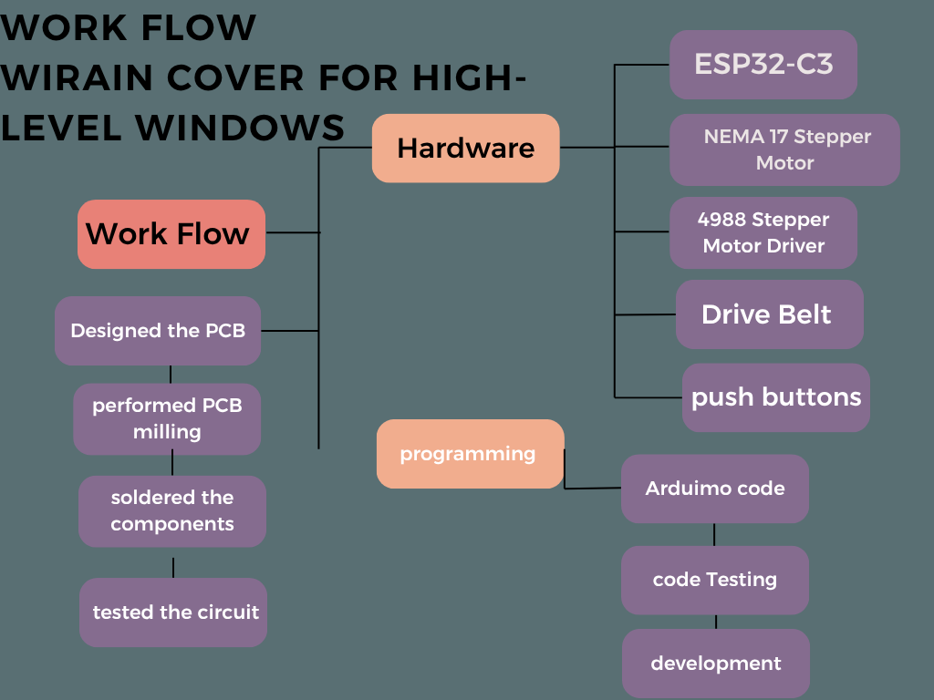
Final Project
Title: Design and Fabrication of WiRain Cover for High-Level Windows
Problem Statement
High-elevation windows, such as those in the Fab Lab at Vigyan Ashram, are prone to rainwater intrusion even when fully closed. This persistent issue poses a risk to sensitive equipment, stored materials, and the comfort of occupants, especially during the monsoon season. Traditional window designs fail to provide adequate external sealing, and manual interventions are inconvenient and often delayed.
To address this challenge, the WiRain Cover project proposes a smart, automated sliding rain protection system. The solution consists of a durable plastic sheet mounted on a rail-based sliding mechanism that can be manually or remotely operated. It provides timely protection by shielding the window externally, without compromising airflow or visibility during dry weather. The system supports manual control via push buttons and remote operation through a Wi-Fi-based interface, offering flexibility and accessibility even in the absence of internet connectivity.
By integrating mechanical design, embedded systems, and wireless control, the WiRain Cover offers a practical and scalable solution to prevent rainwater ingress in high-elevation windows. Future enhancements such as automatic rain sensing and smart system integration can further increase its utility and automation potential in smart buildings.
Objectives of the Project
My objective is to solve the problem of rainwater leaking through high-level windows, especially during heavy rains. I aim to create a smart sliding cover that can protect the window from rain and keep the inside safe and dry. The system should be easy to control both manually and remotely through Wi-Fi. I want to combine mechanical design and technology to make this solution practical and reliable. Finally, I plan to build it so future upgrades like automatic rain detection can be added easily.
Abstract :
The WiRain Cover project addresses the problem of rainwater intrusion through high-level windows, which can damage equipment and disrupt indoor comfort. This project proposes a smart, automated sliding rain protection system made of a durable plastic sheet mounted on a rail mechanism. The system offers dual control modes: manual operation via push buttons and remote control through a Wi-Fi-enabled interface, ensuring flexibility and ease of use. Designed to prevent water ingress while maintaining airflow and visibility, the WiRain Cover demonstrates the integration of mechanical design, embedded systems, and wireless communication. Future enhancements could include automatic rain sensing and smart building integration, making it a scalable and practical solution for protecting elevated windows.
Environment and Safety
The project falls under Environment and Safety as it protects indoor spaces from rainwater intrusion. By preventing moisture from entering high-level windows, it safeguards equipment and ensures user comfort. This promotes a safer, more reliable working environment during adverse weather.
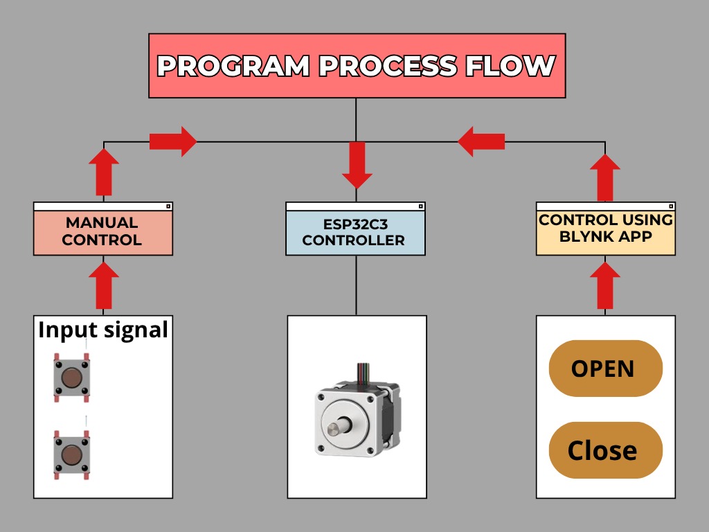
WiRain Cover System Diagram
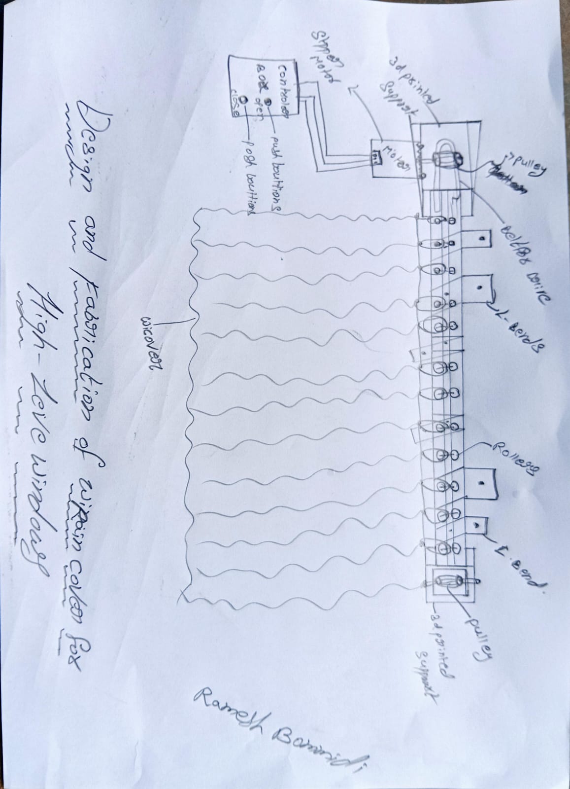
sketch of my final project :
Bill of Materials (BoM) :
| Item | Qty | Cost (INR) |
|---|---|---|
| ESP32-C3 | 1 | ₹300 |
| Stepper Motor | 1 | ₹250 |
| Motor Driver A4988 | 1 | ₹150 |
| Plastic transparent Cover | 1 | ₹200 |
| Push Buttons | 2 | ₹40 |
| Limit Switches | 2 | ₹60 |
| Aluminum rails | 1 | ₹500 |
| Power Adapter | 1 | ₹150 |
| pcb | 1 | ₹100 |
| 10M GT2 Width 6mm White Open Timing Belt | 1 | ₹300 | Misc (wires, nuts, etc.) | nun | ₹100 |
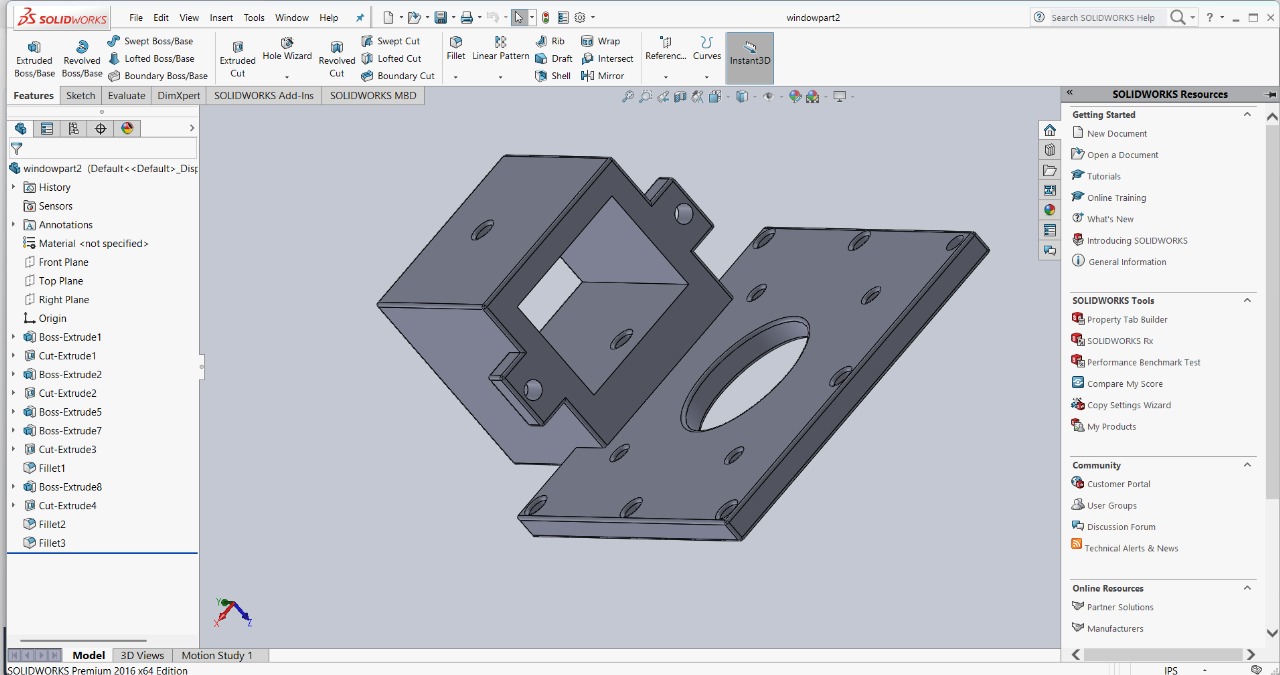
3D Modeling and Drafting :
I used SolidWorks to create both 3D models and 2D technical drawings of the project components. I also used the assembly feature to combine individual parts and check how they fit and move together. This helped ensure the design was accurate and functionally correct before fabrication.
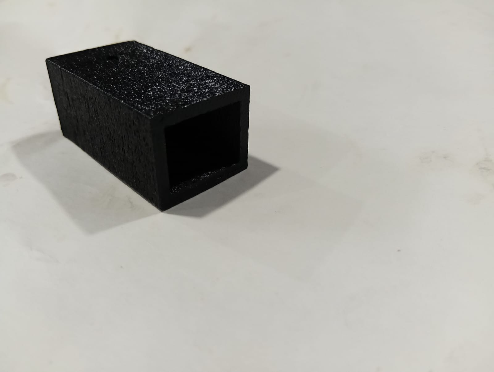
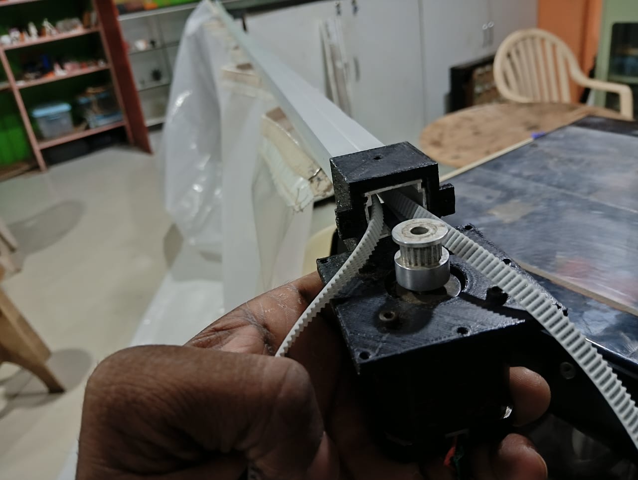
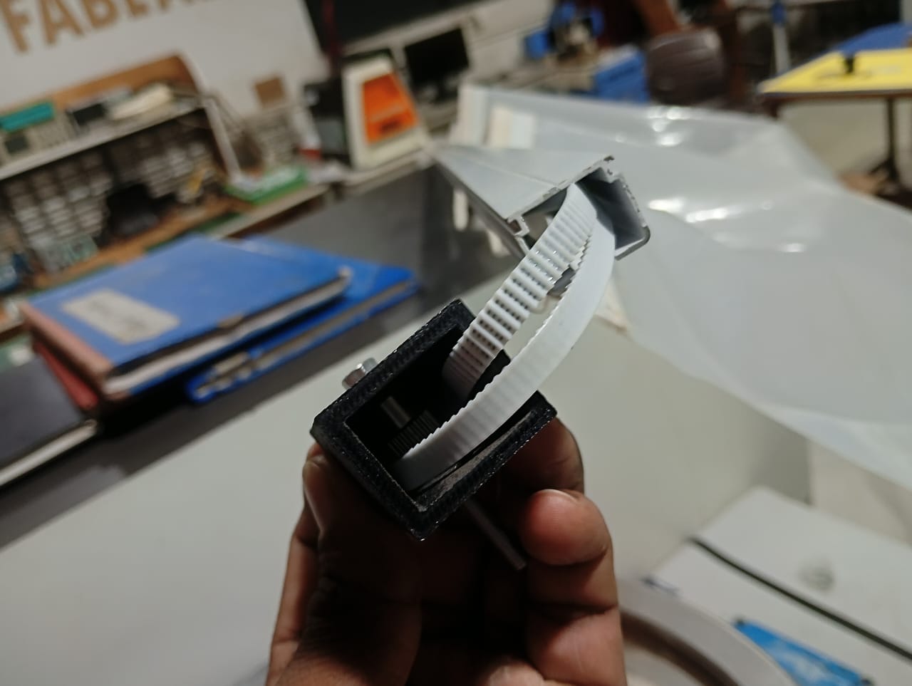
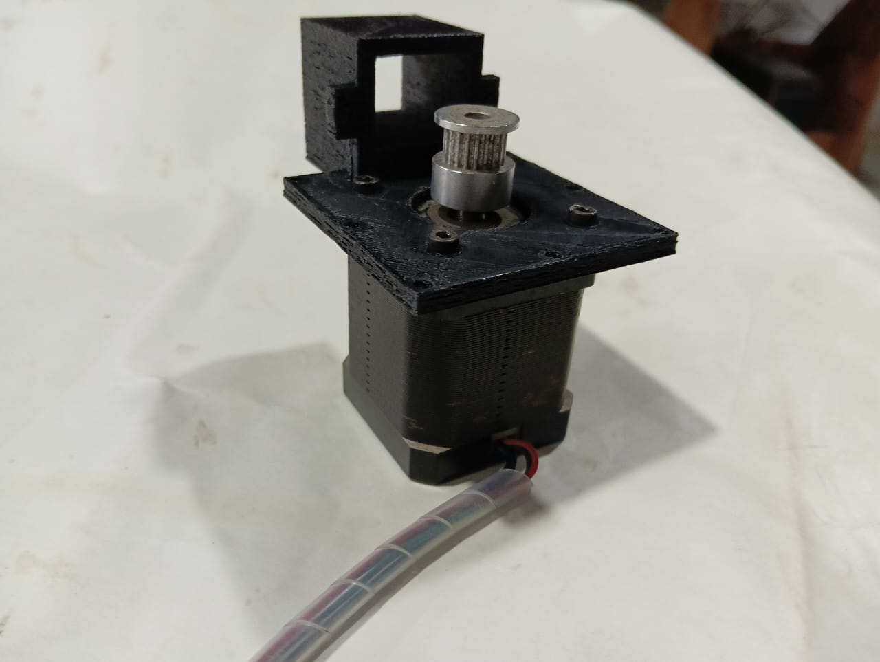
I created motor supports and pulley supports in SolidWorks for the belt drive mechanism. These components were designed to securely hold the motor and pulleys in place, ensuring proper alignment of the belt. This setup helps transmit motion smoothly and efficiently in the mechanical system.
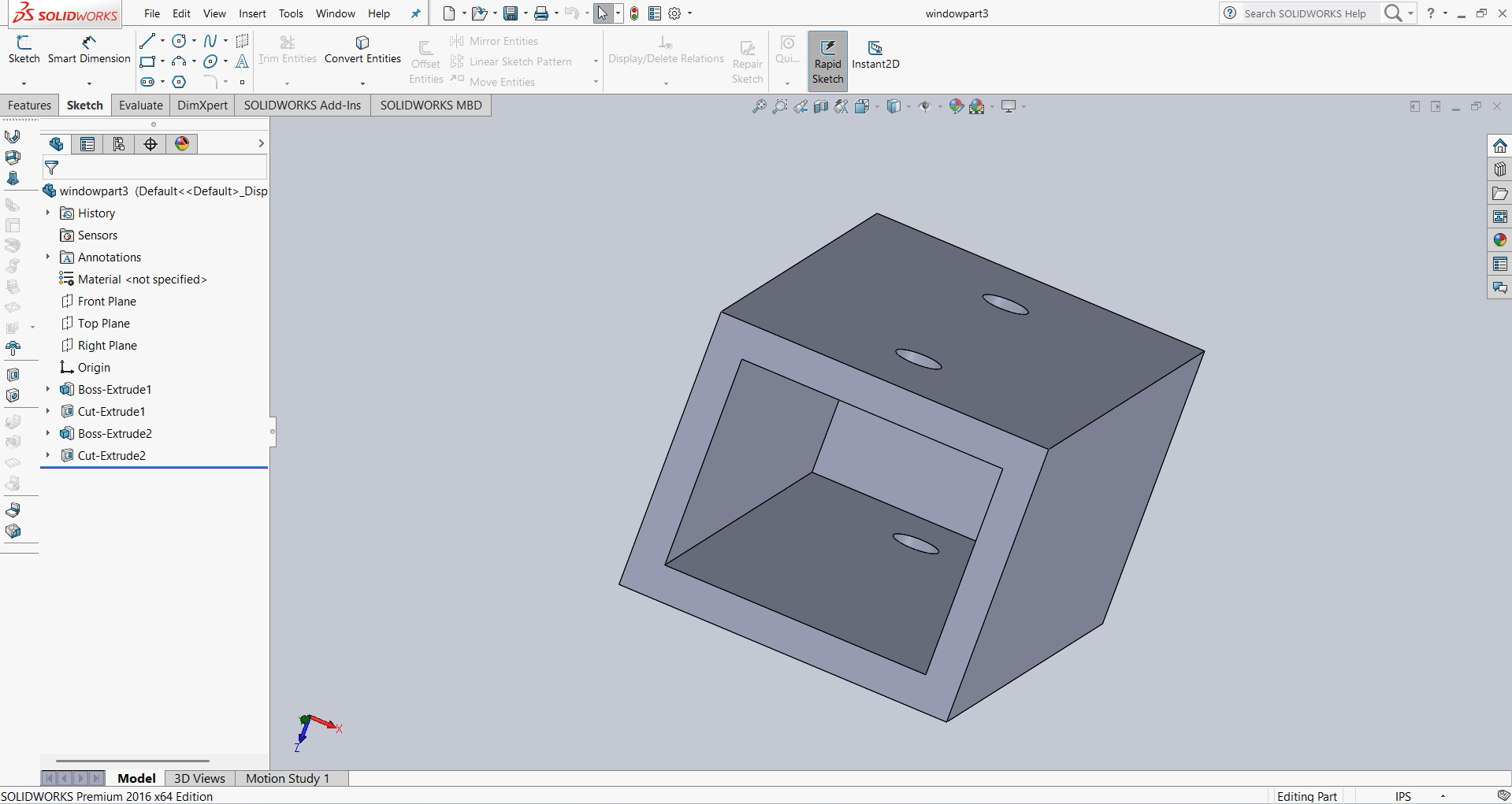
I designed a components box in SolidWorks to house the manual control system. The box includes space for push buttons and wiring, ensuring safe and organized control. Its design allows easy access for operation and maintenance.
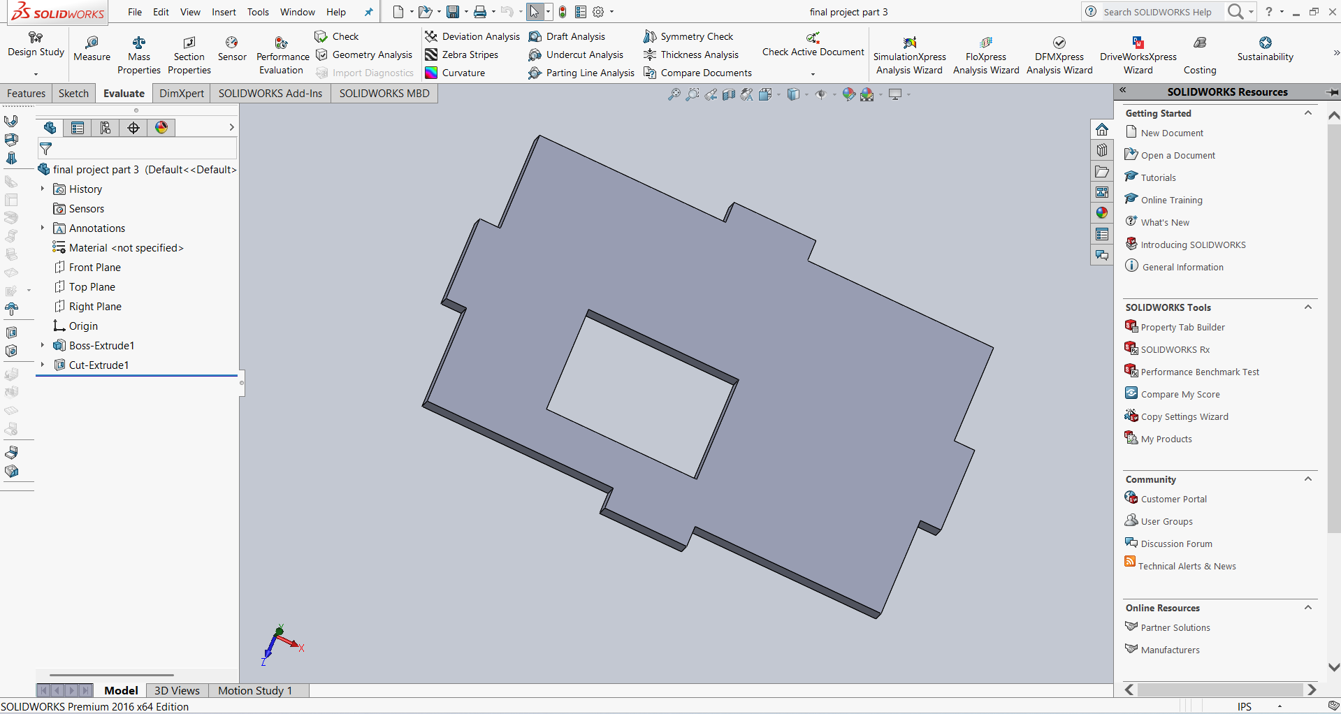
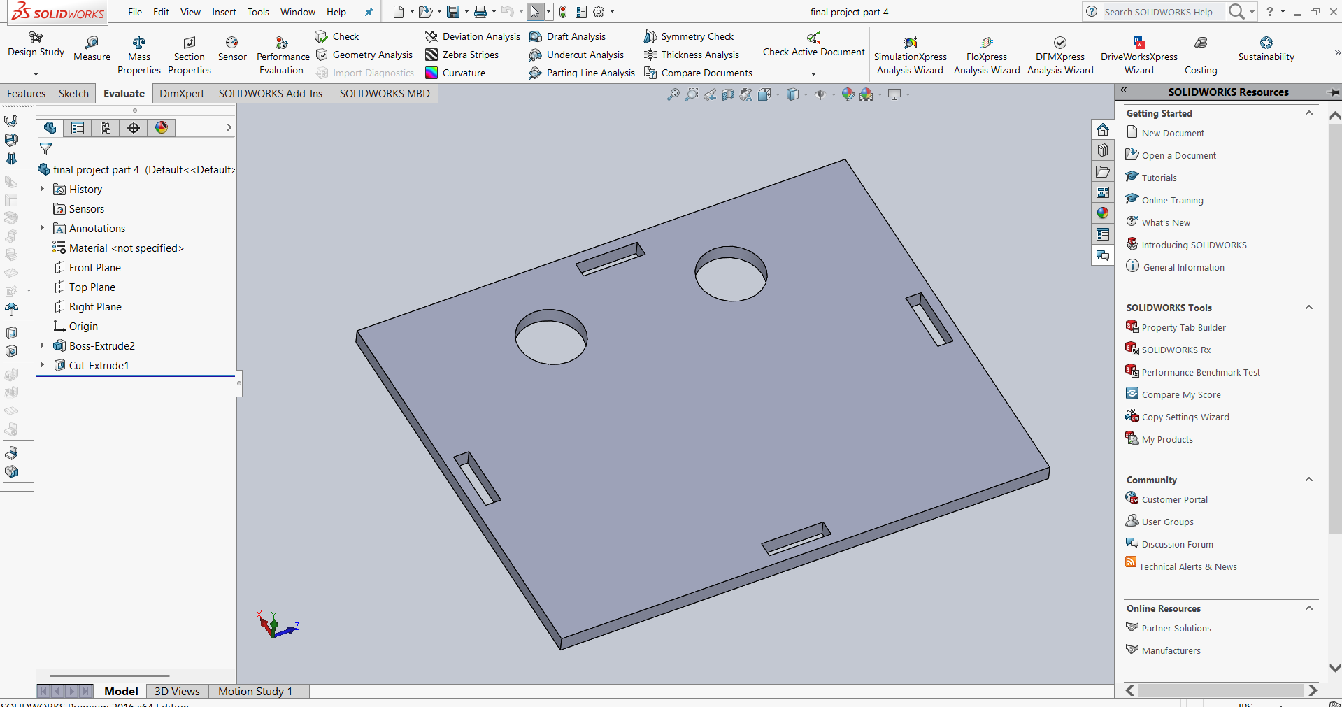
Below I am showing the design of the base plate and side plates of the manual control box.
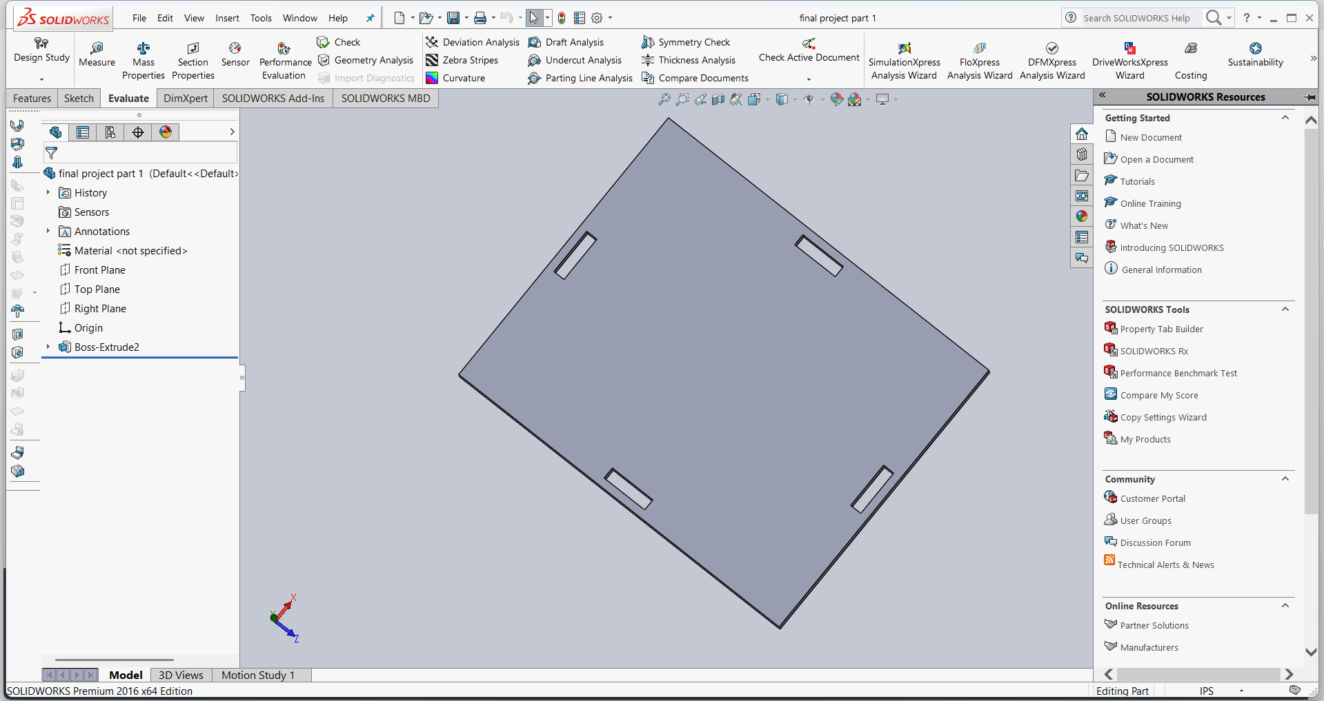
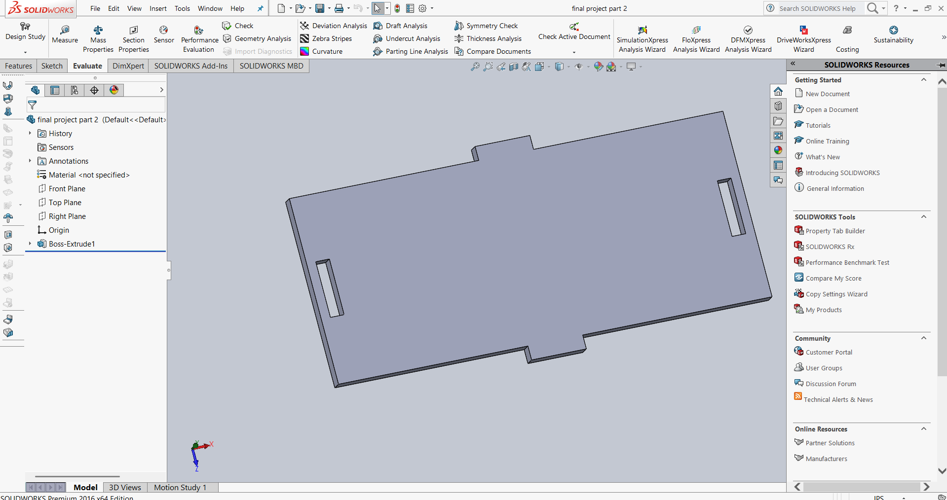
Below I am showing the design of the top plate, front plate, and bottom plate of the manual control box.
Assembling of the manual control box

3D Printing Workflow :
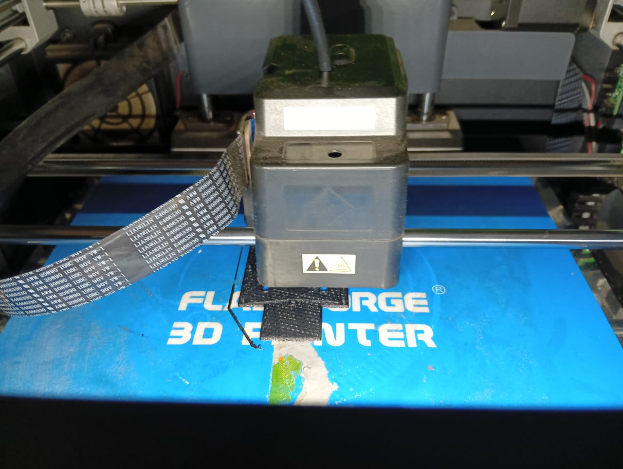
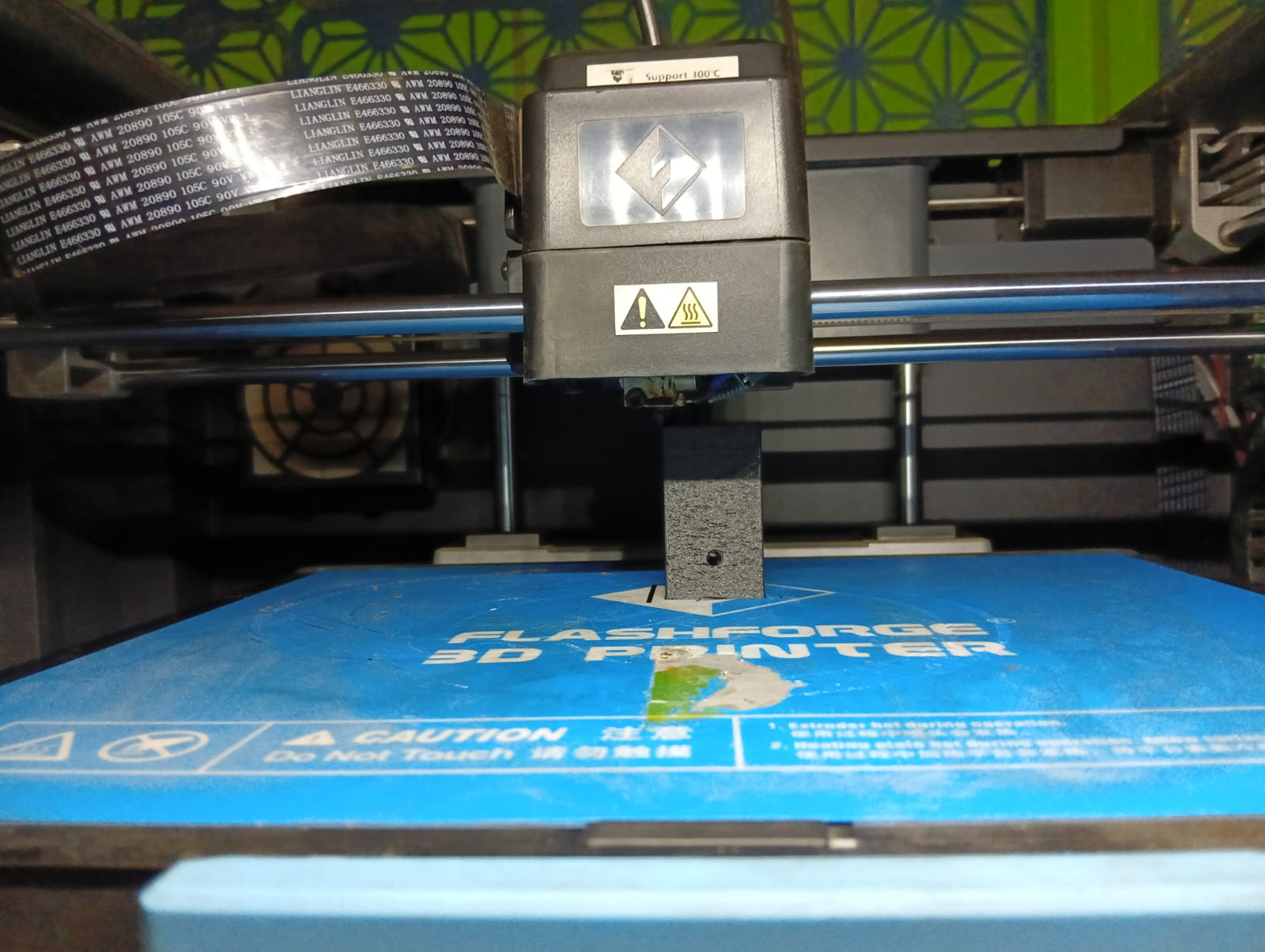
After completing the 3D printing process, the output parts were carefully inspected and cleaned.
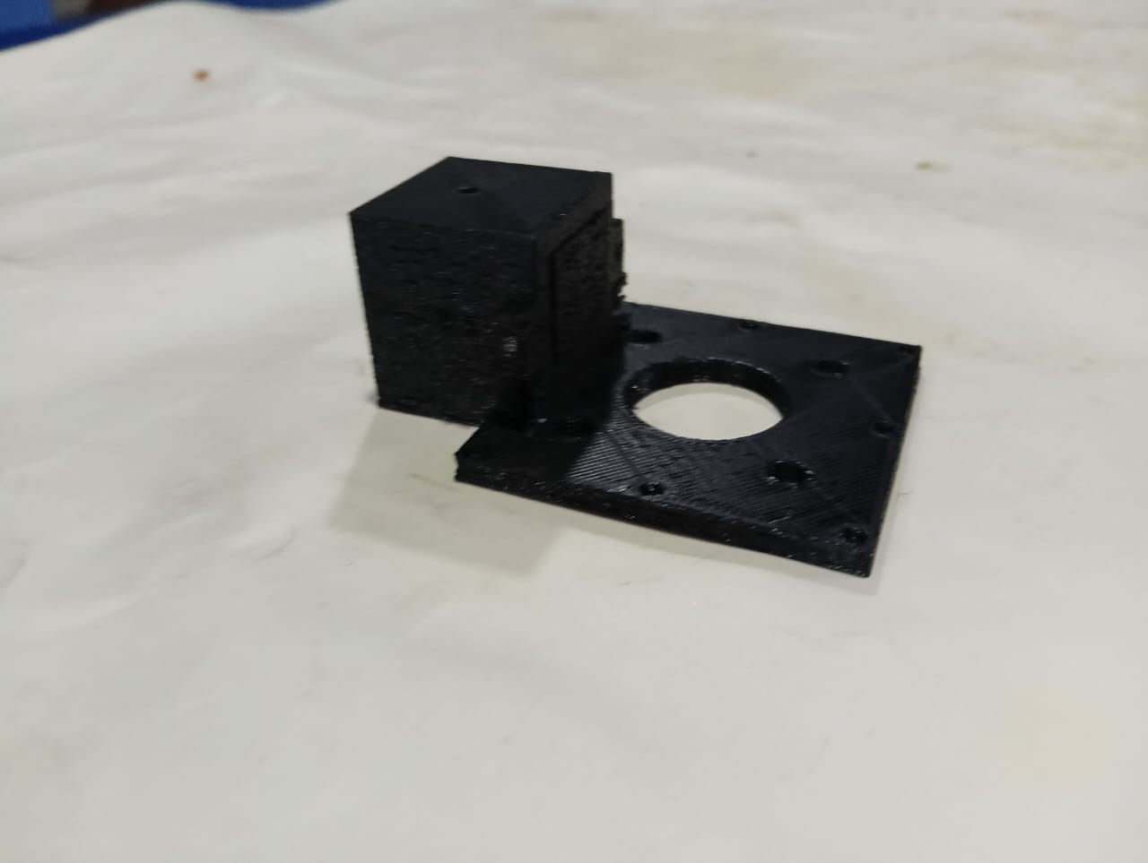
Assembling of 3D Printed Parts
The 3D printed parts were assembled carefully to form the complete structure. Proper alignment and fitting were ensured for smooth functionality.
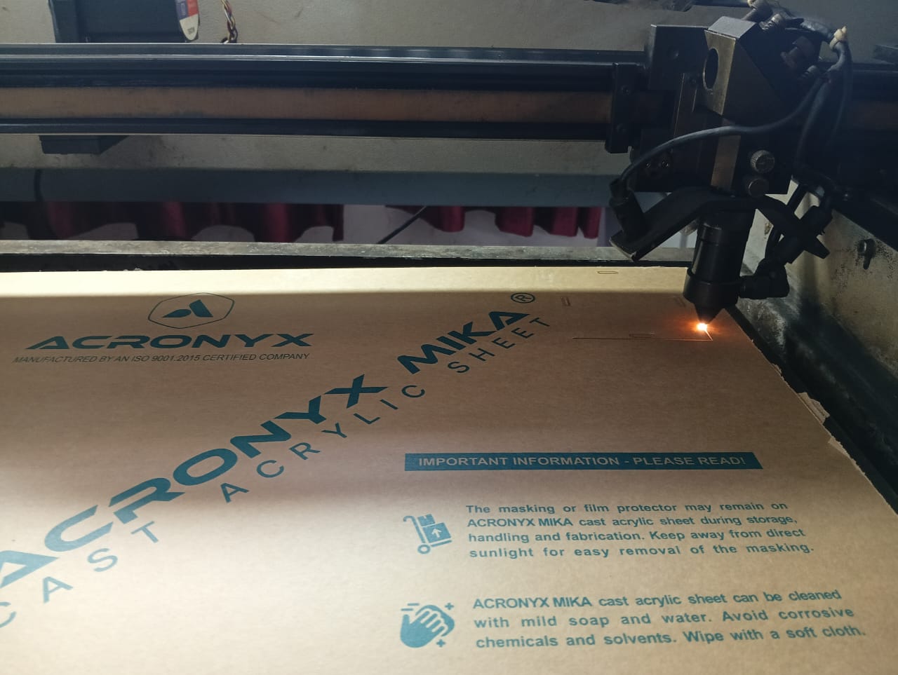
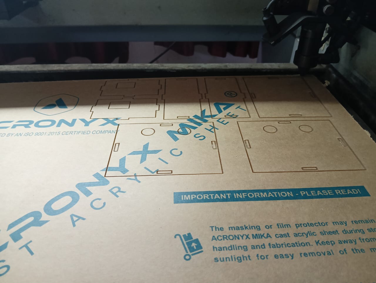
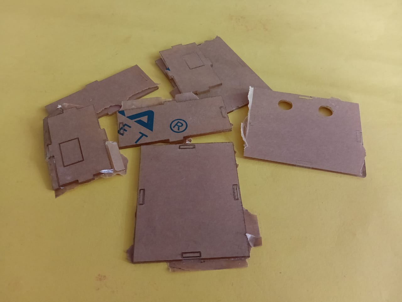
Laser Cutting Workflow :
Cutting the manual control box parts was carried out using the laser cutting process to achieve precise and clean edges.
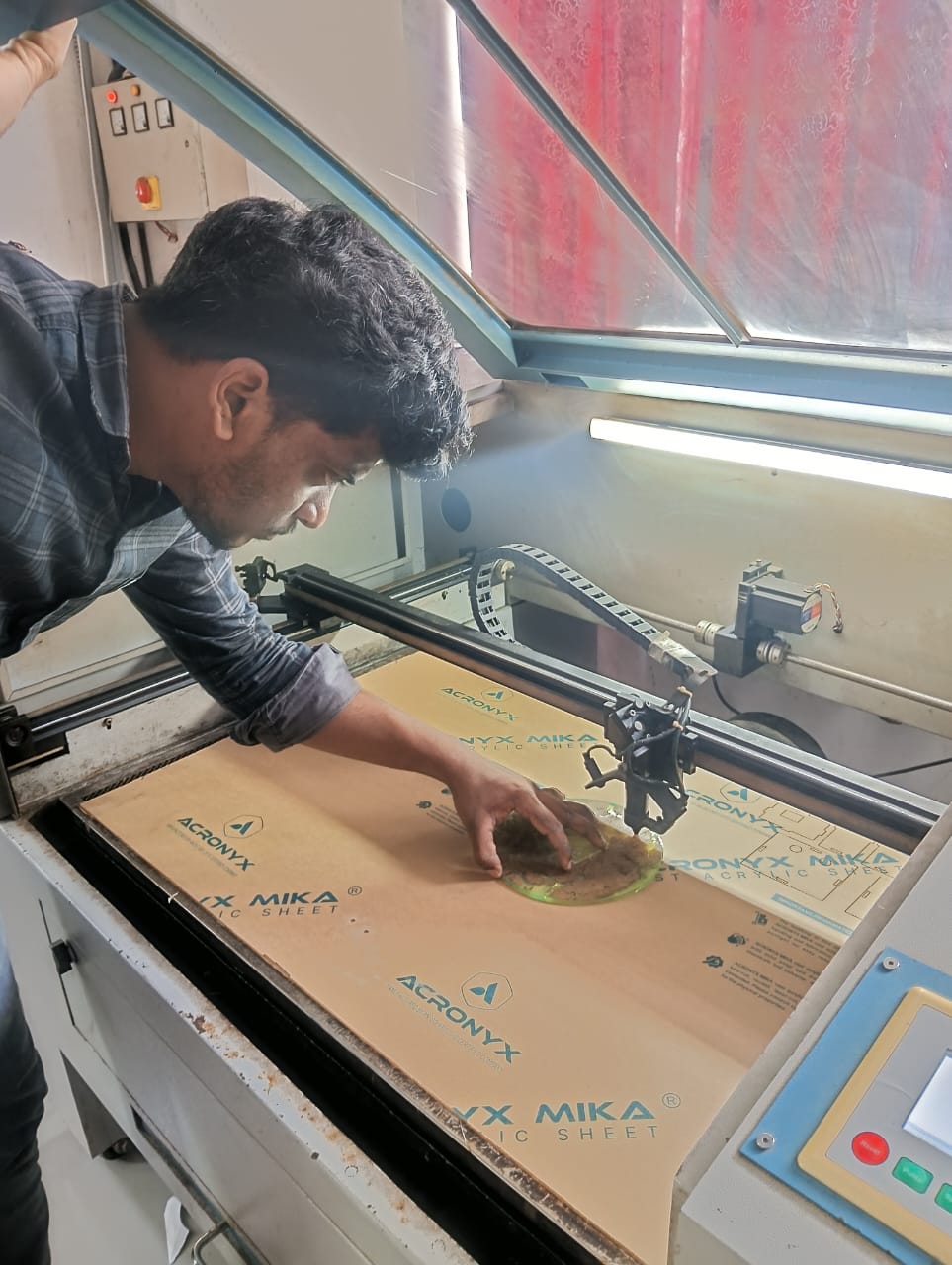
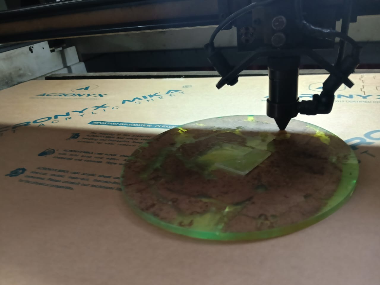
Below, I am showing how the laser cutting process shapes the parts with precision. This method ensures clean edges and accurate dimensions.
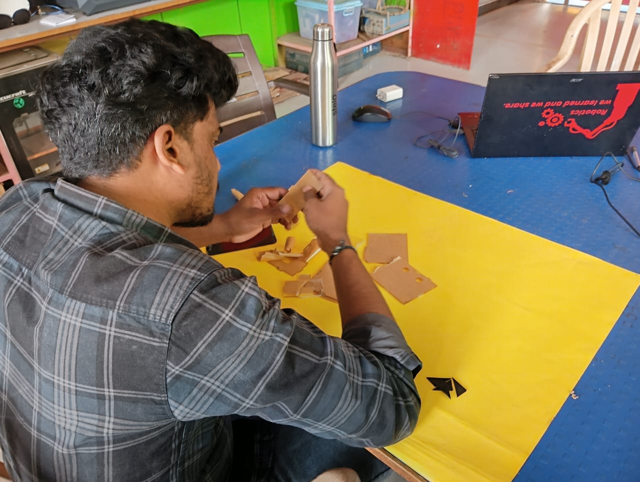
Control Box Assembly Process :
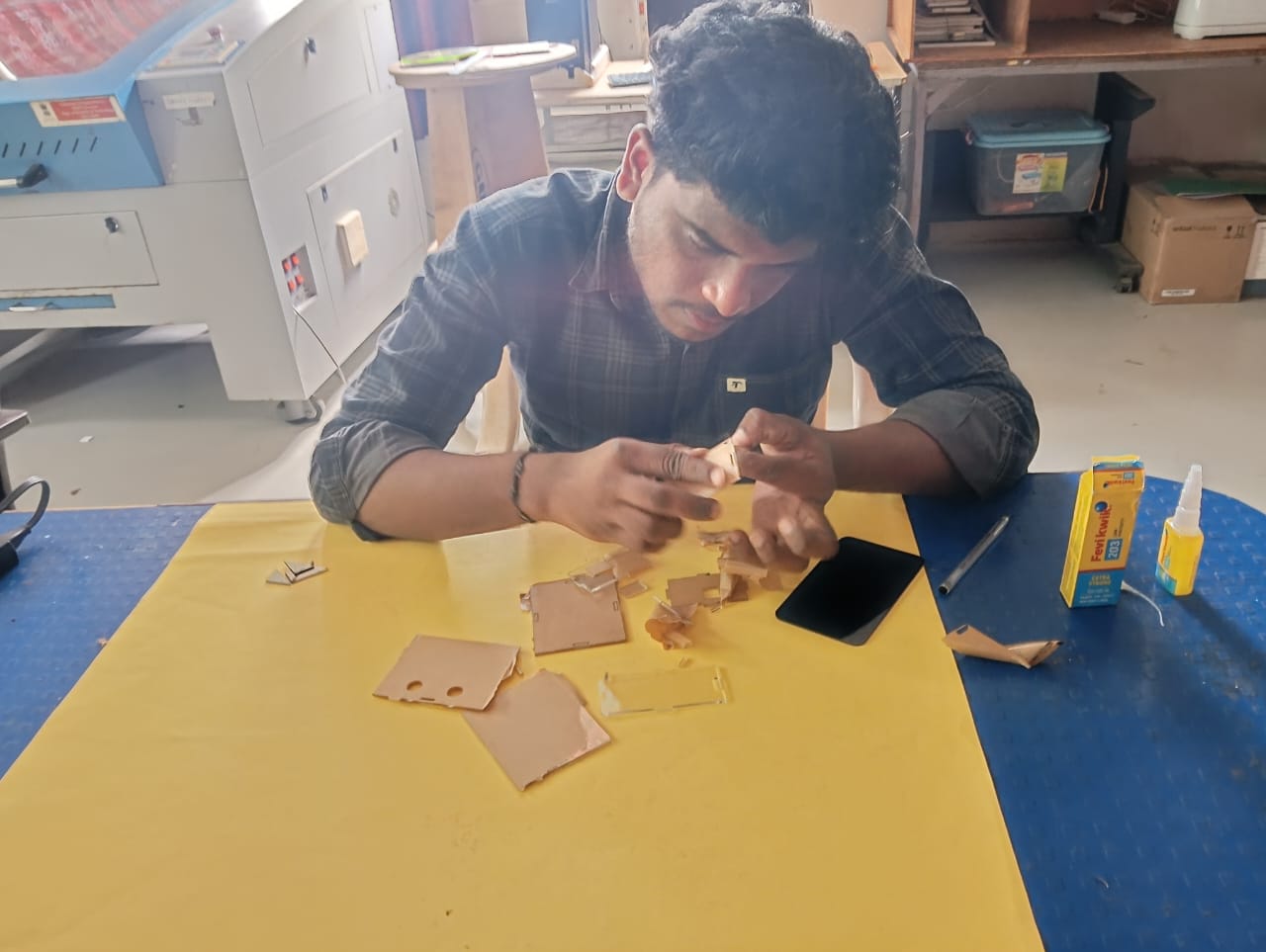
After completing the laser cutting, I started the assembly of the control box by joining all the cut parts together accurately.
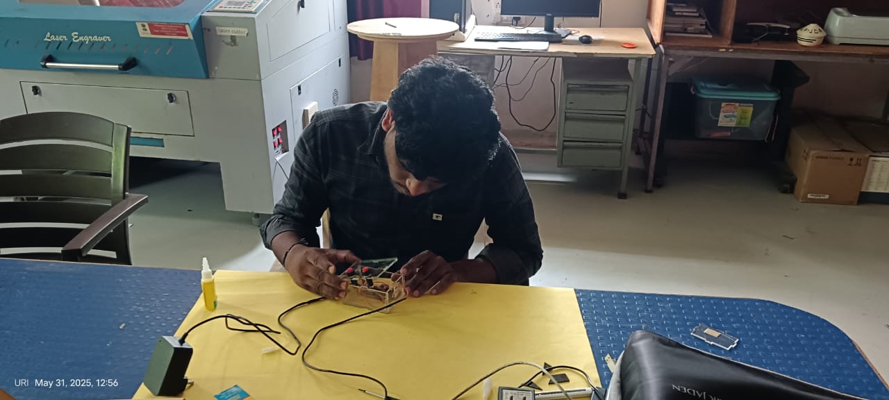
Fixing the electrical components in the box was done carefully by placing each part in its designated position. All components were secured properly to ensure safe and reliable operation.
Electronics Production Workflow :
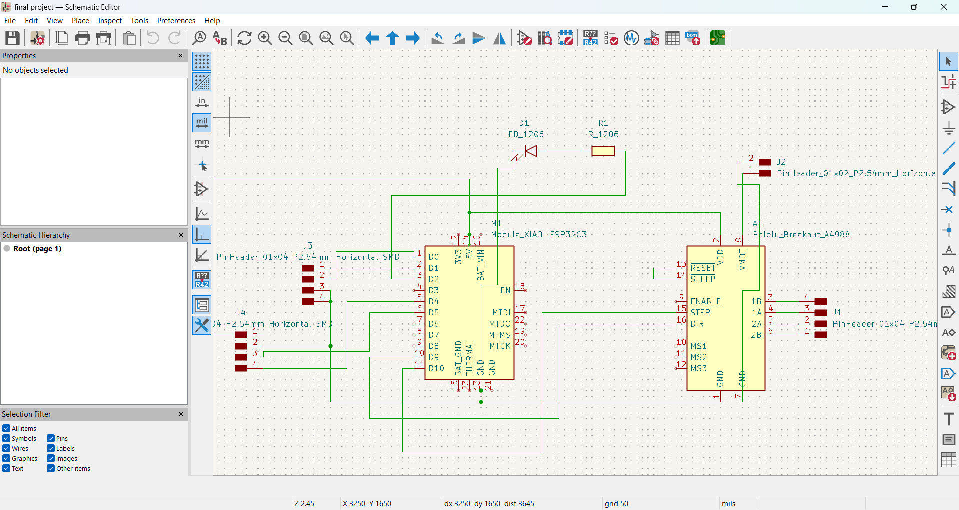
- Designing the PCB :
Below, I am showing how I created the schematic diagram and designed the PCB for my final-project.
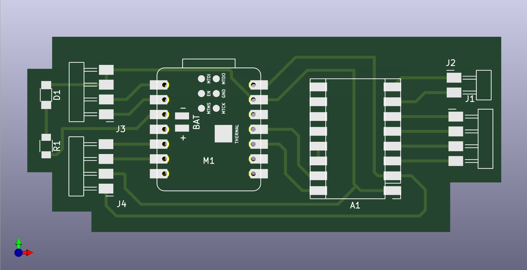
PCB design in 3D view :
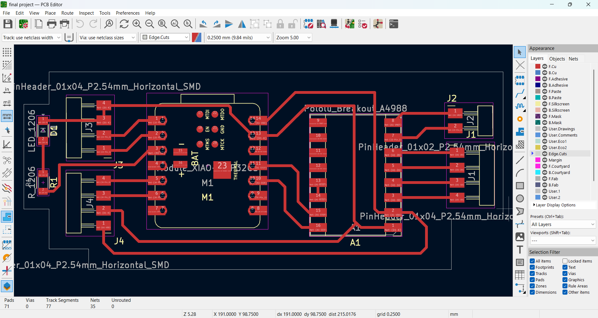
- PCB Milling Process :
After completing the PCB design using KiCad, I exported the file into my pc. Below, I am showing an image .
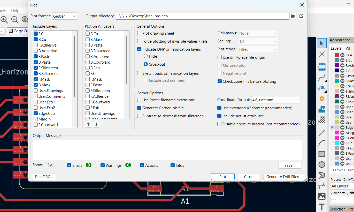
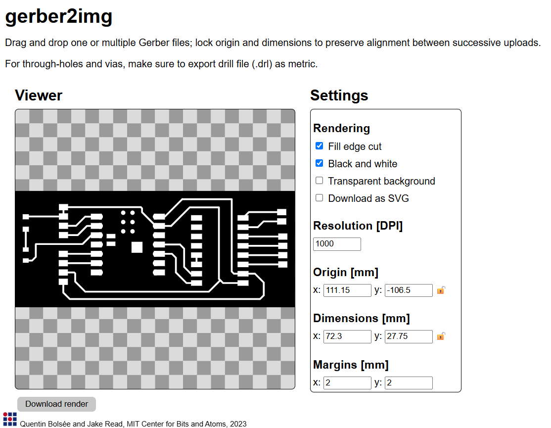
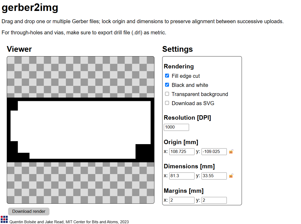
I converted the Gerber files to PNG format using the gerber2image tool. This helped visualize the PCB layers before the milling process.
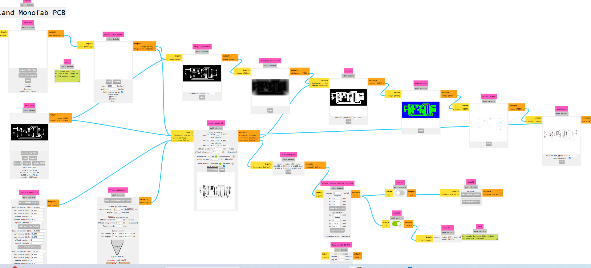
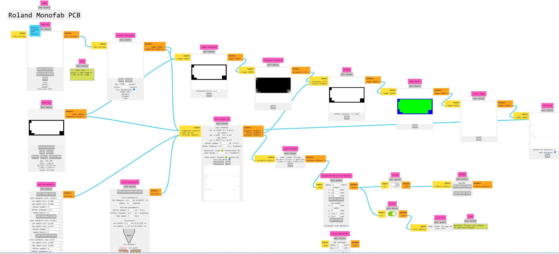
Creating Milling Toolpaths Using Mods C :
I generated the toolpath for PCB milling using Mods C configured for the SRM-20 machine. This step ensures accurate milling paths tailored for the Roland SRM-20.
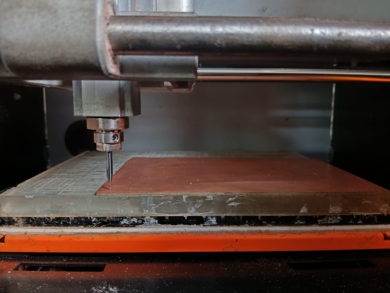
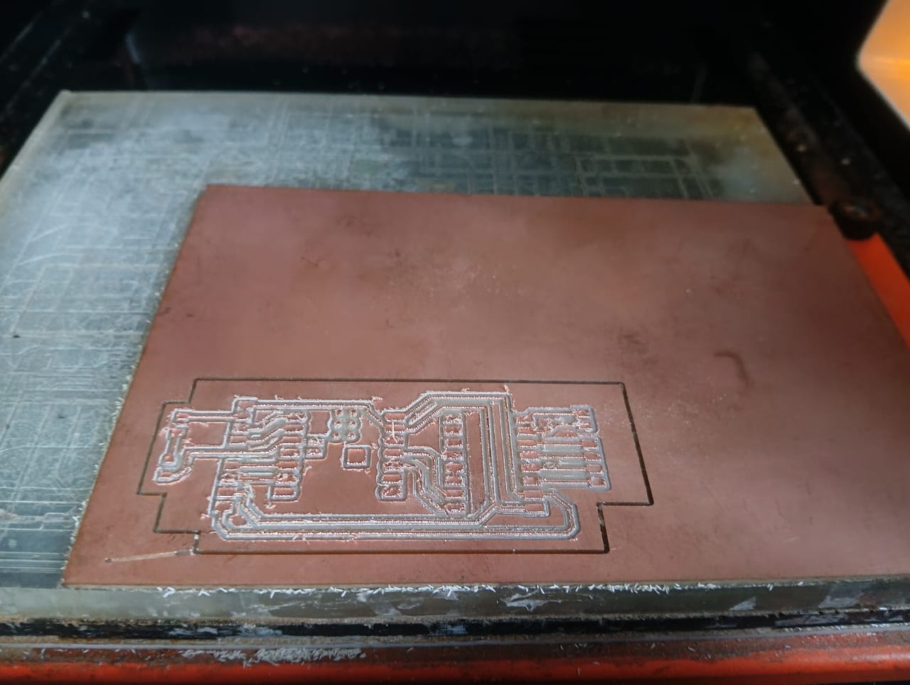
After completing the toolpath generation, I started the PCB milling process. Before beginning, I set the SRM-20 machine to the origin position and initiated the process with the trace mill. Below, I am showing how the machine milled the PCB trace cut.
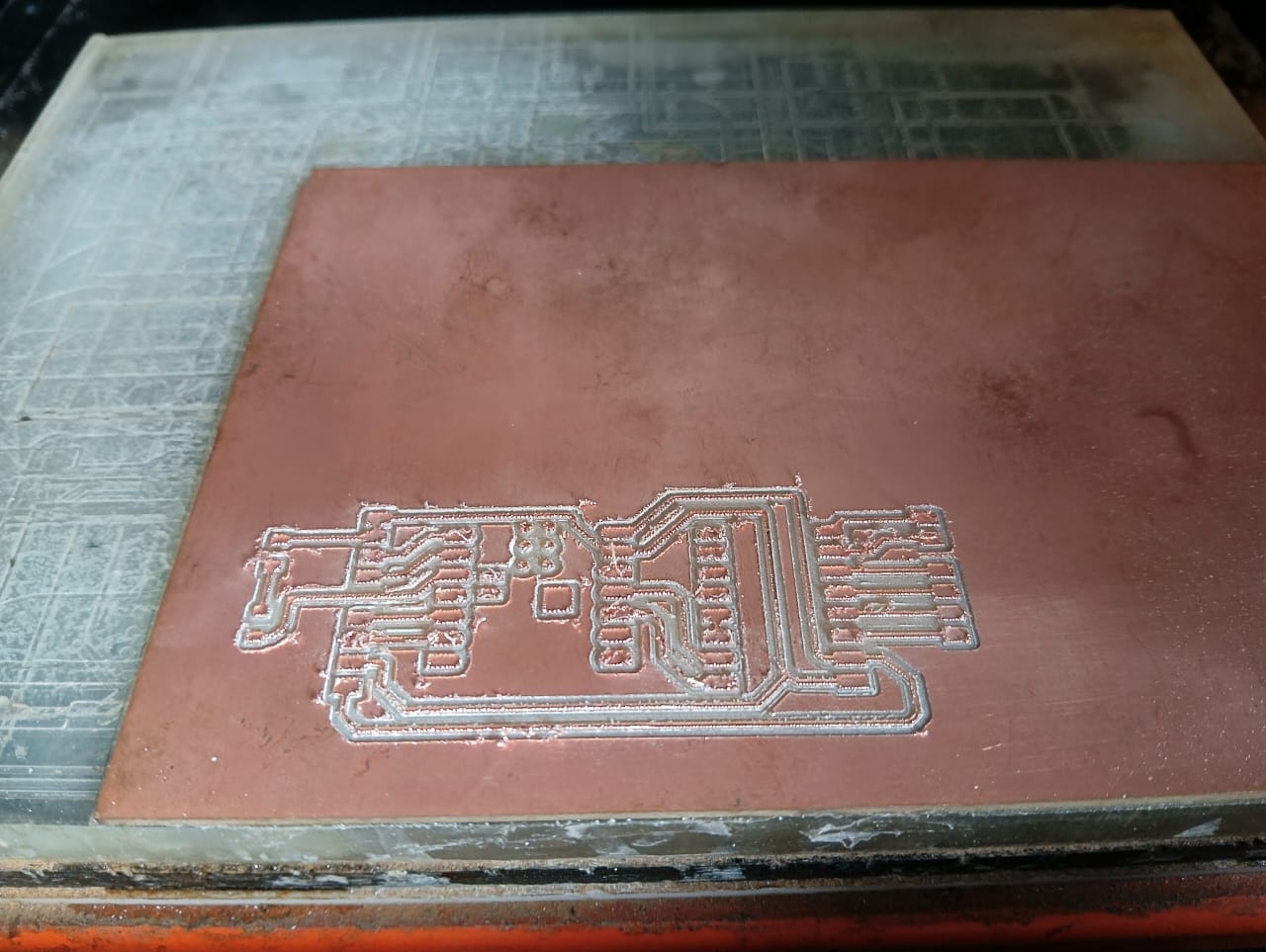
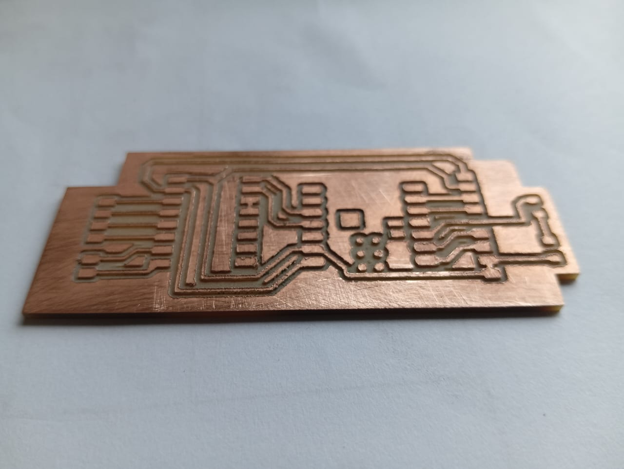
After completing the trace cut, I proceeded with the edge cut to shape the final PCB. Below, I am showing how the edge cut was performed, along with the final result of my milled PCB.
Soldering Workflow :
Components Required for my Final Project board:
1. ESP32-C3
2. A4988 Stepper Driver
3. 1kΩ Resistor
4. 0.1µF Capacitor
5. 4-pin Headers (3 pieces) and 2-pin Headers (1 piece)
6. LED (1 piece)
7. Push Buttons (2 pieces)
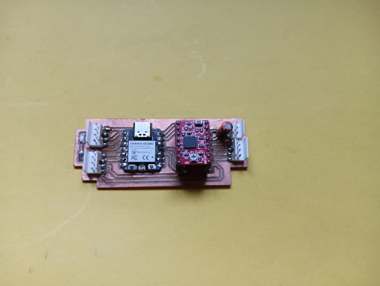
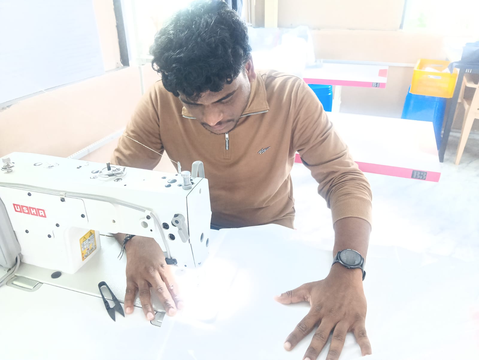
After completing the milling process, I started soldering the components onto my board. I soldered all the components according to my design
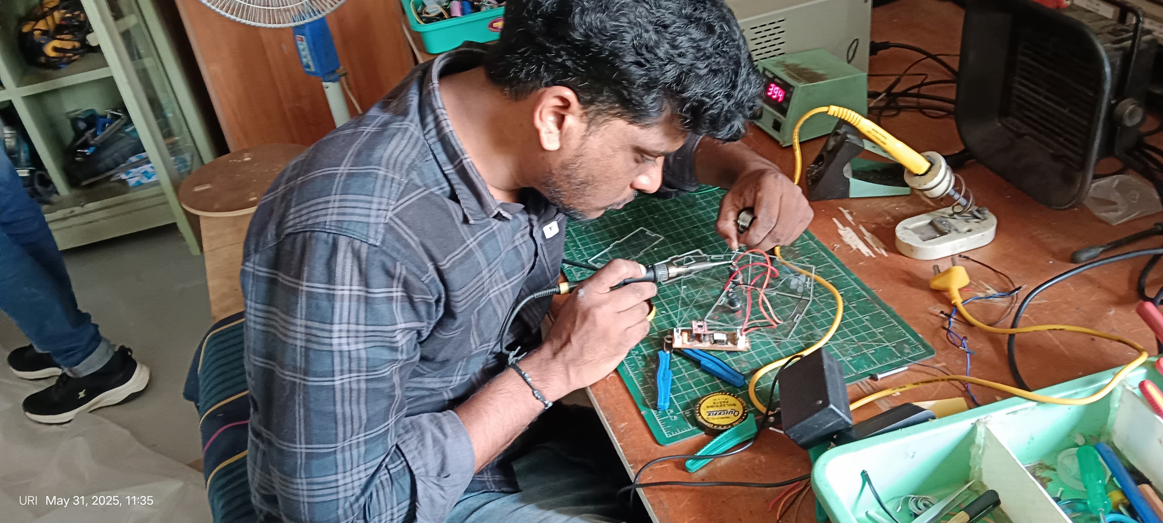
Below, I am showing the final assembled product of PCB.
Preparing the WiRain Cover Wiring Workflow :
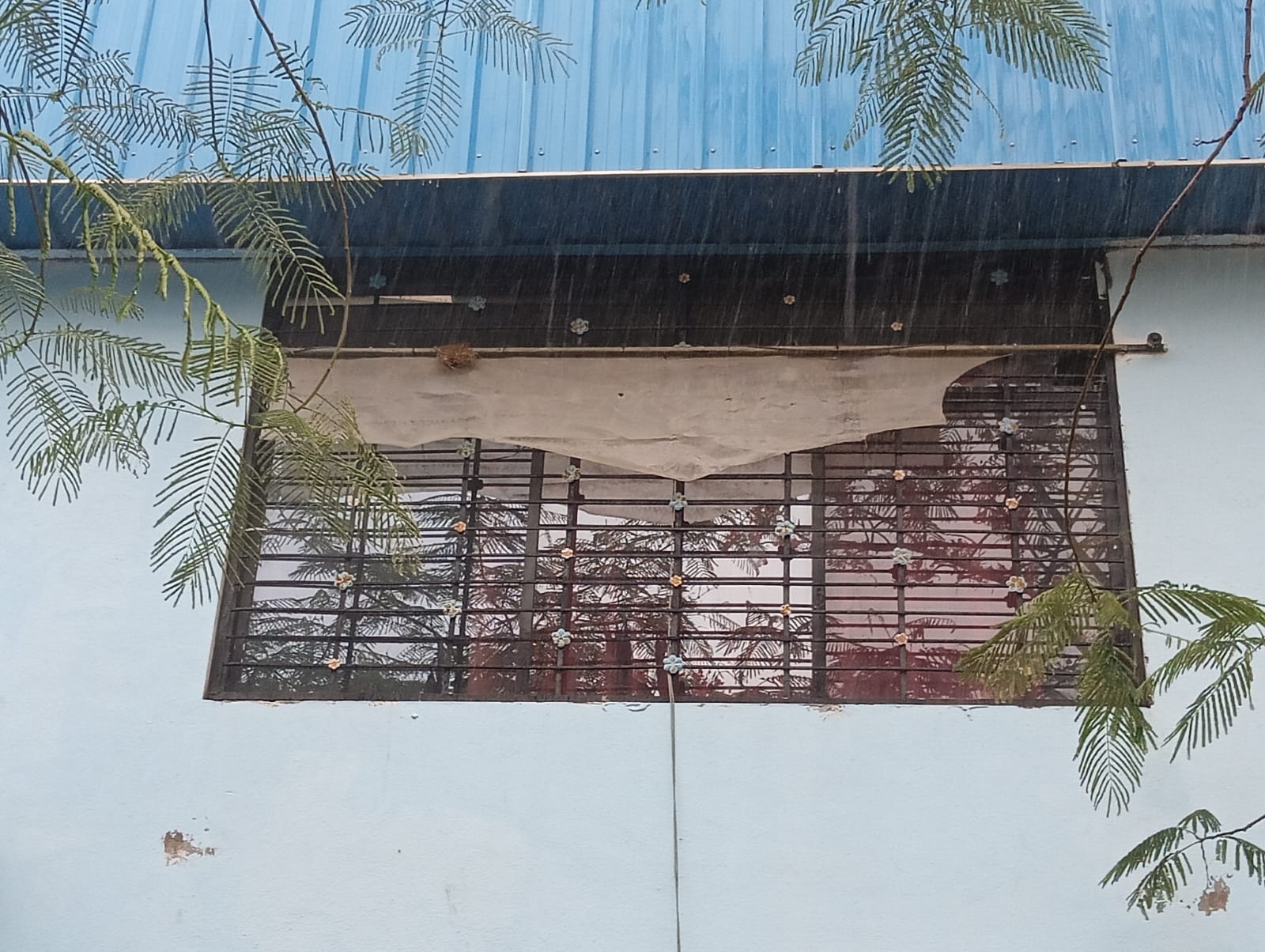
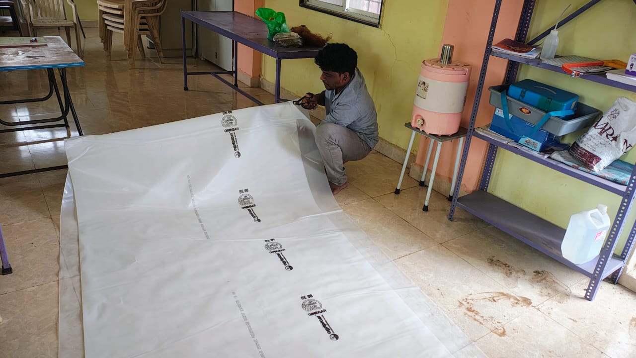
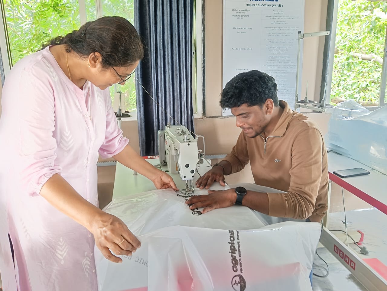
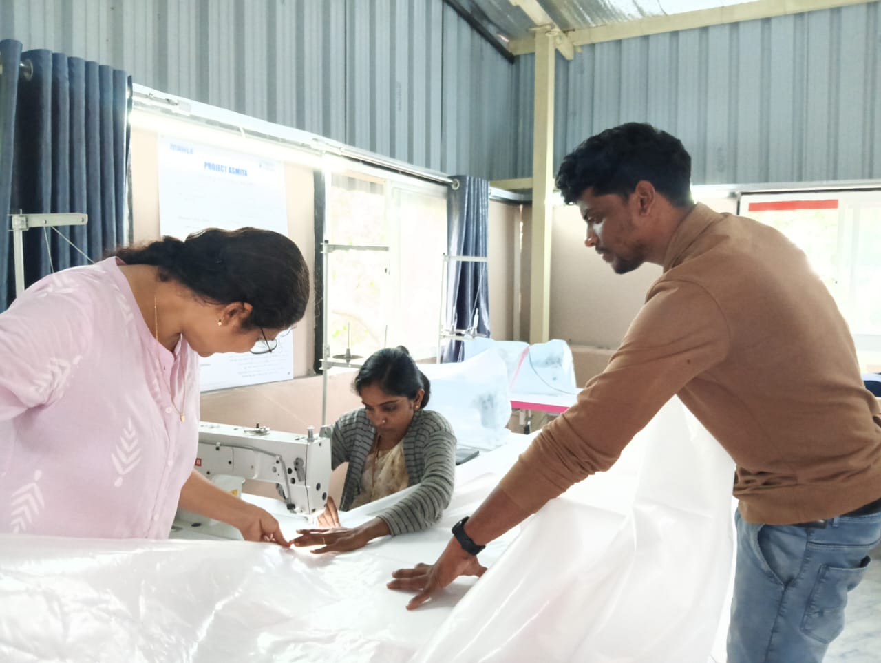
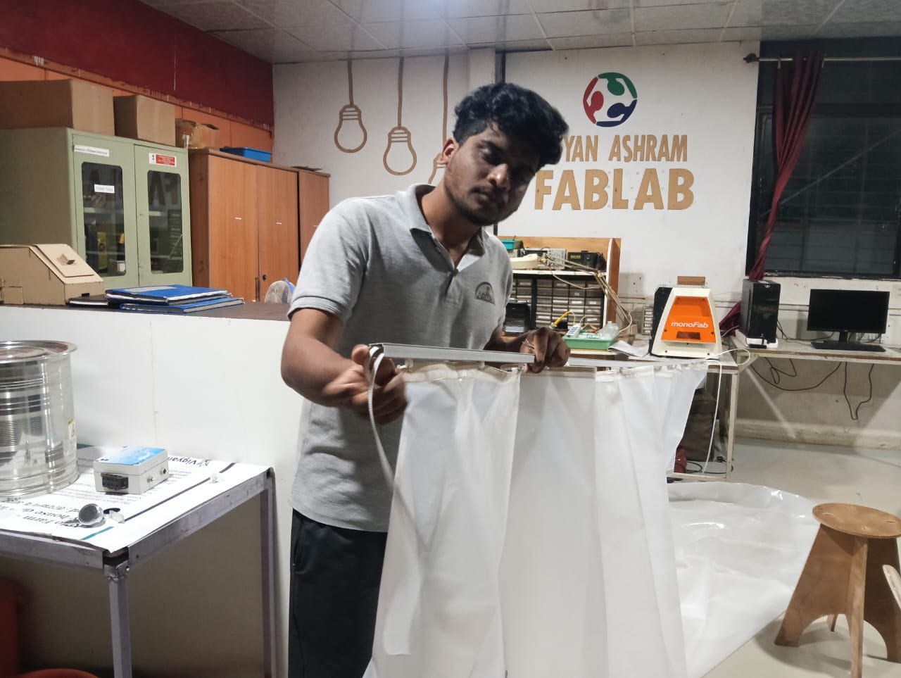
For preparing the WiRain Cover, I used the plastic sheet material typically used for constructing polyhouses at Vigyan Ashram. I took a small portion of this material for the cover. After that, I planned to attach rollers to enable the sliding mechanism. For this, I went to Ashmitha Lab in Vigyan Ashram and discussed the idea of how to properly fix the sliding system.
After completing the discussion, they gave an idea. Based on that, I started the work. Below, I have given the step-by-step process.
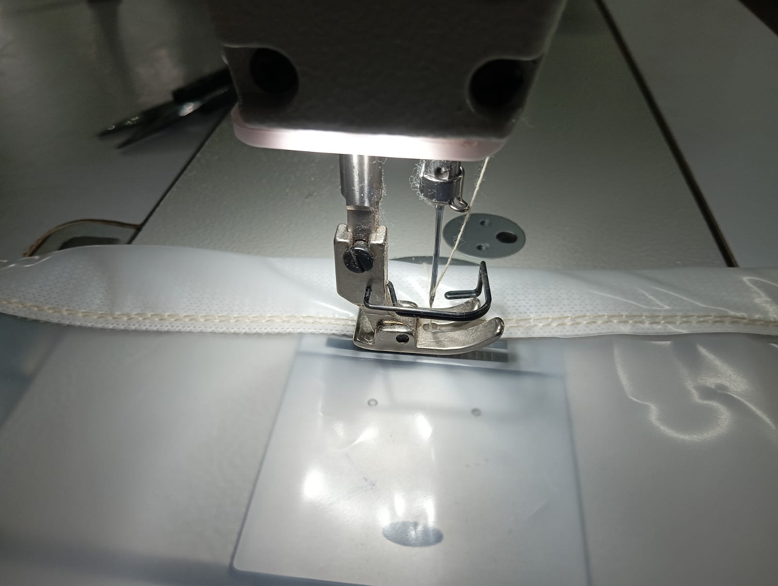
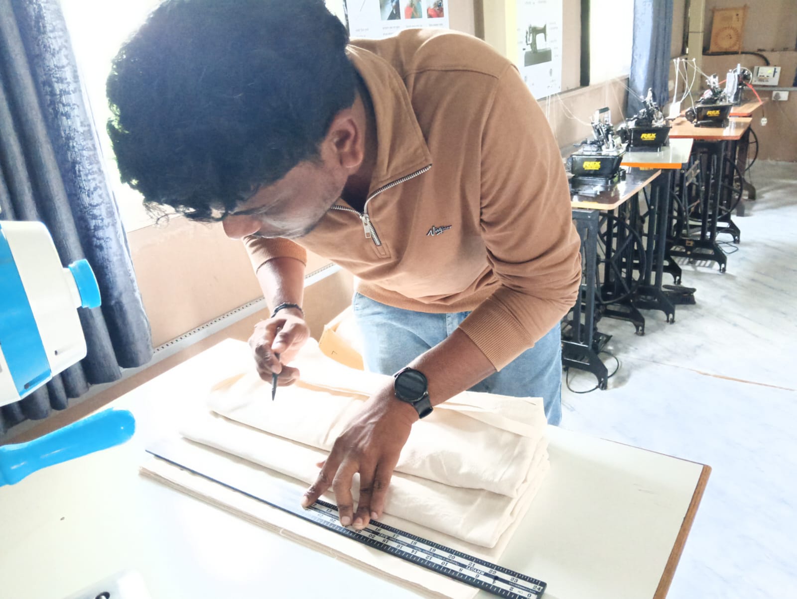
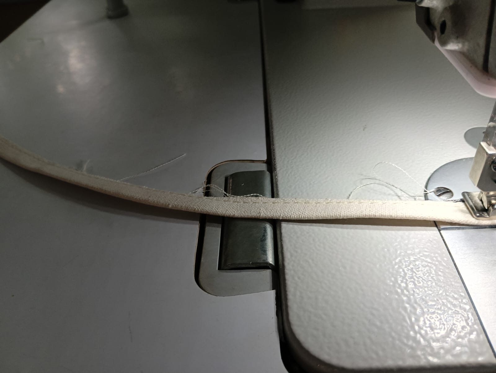
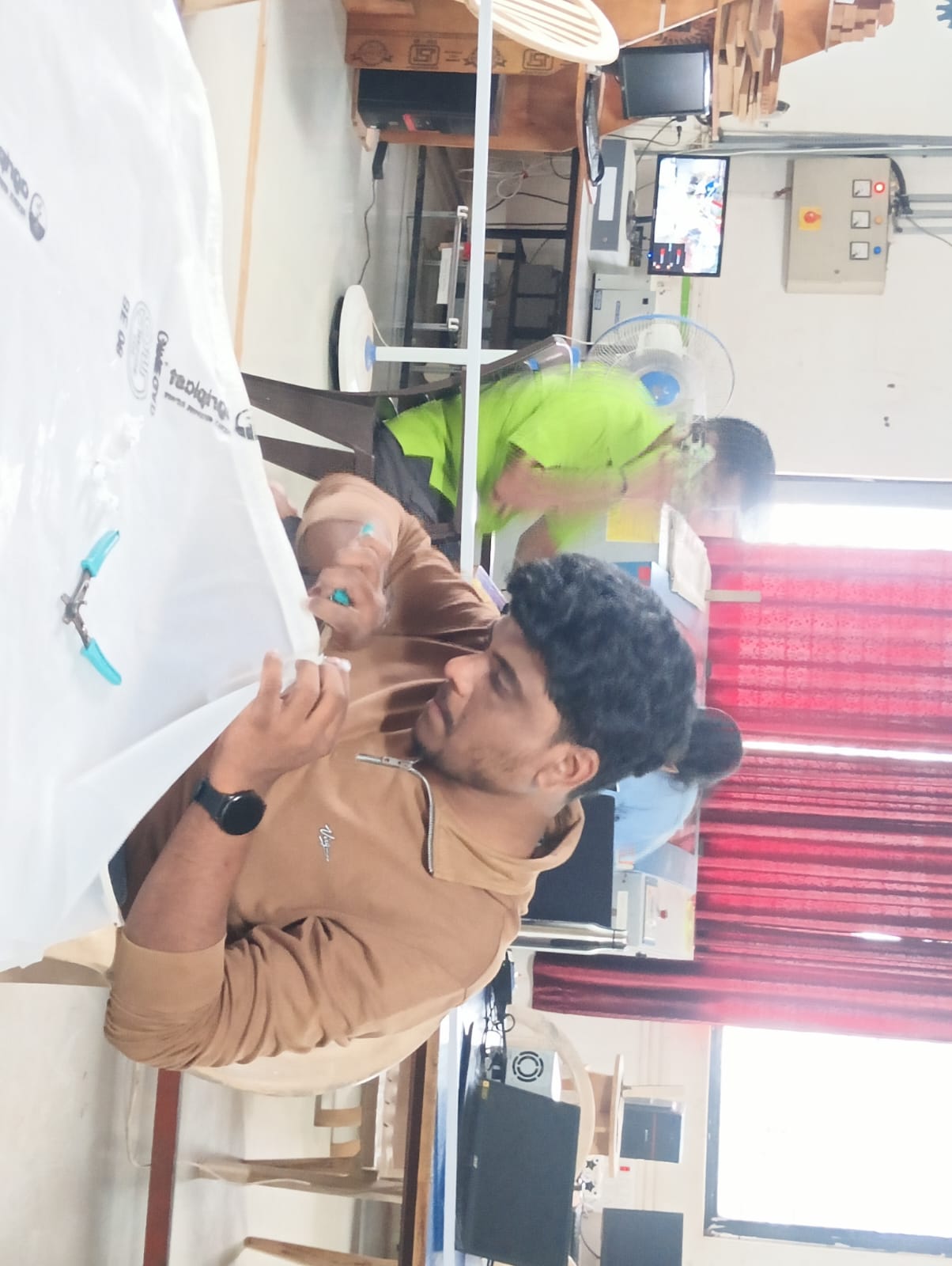
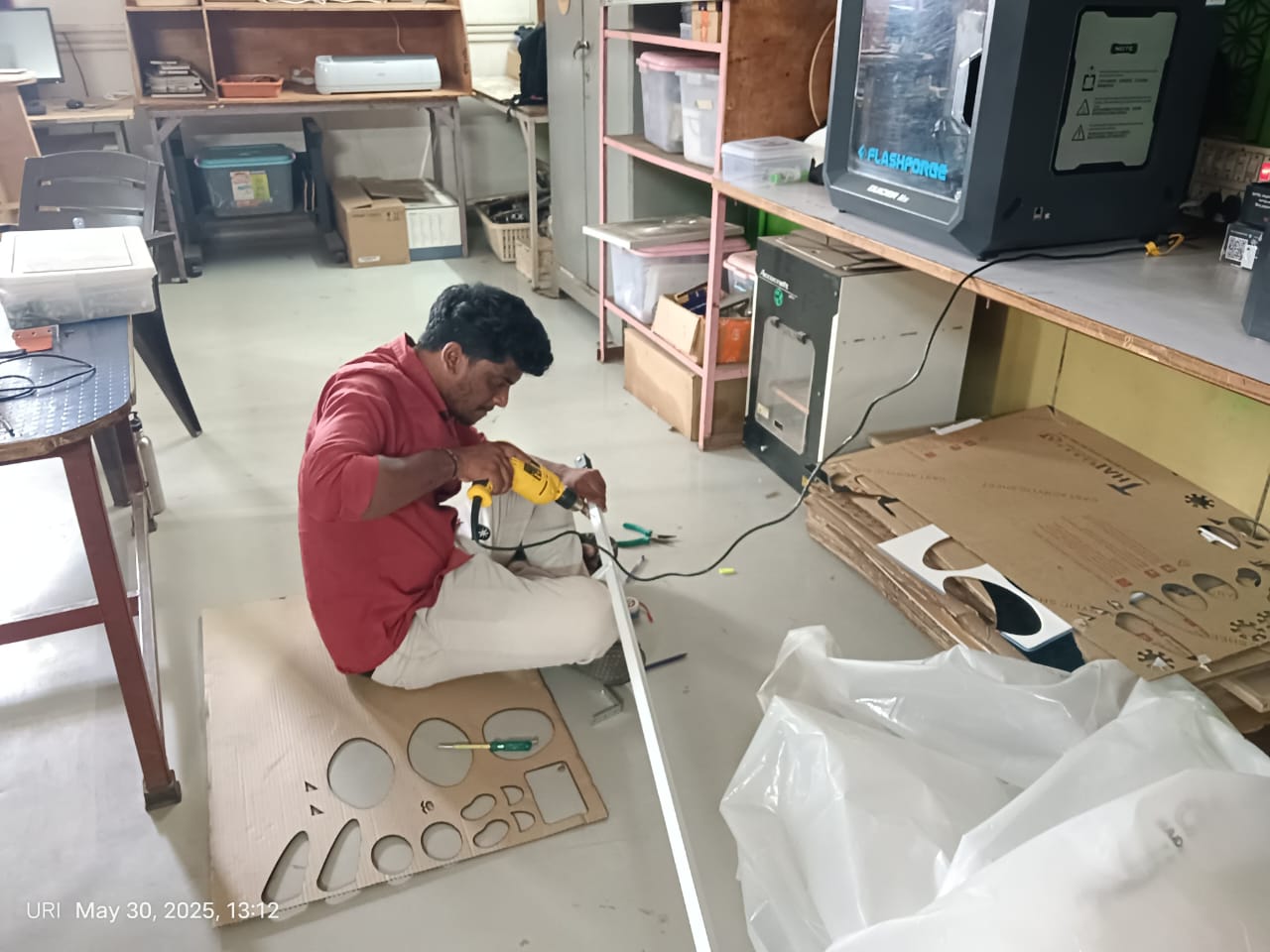
First, I wanted to create a support structure to hang the cover. This support would ensure that the cover remains strong and stable. For this, I cut some waste material available in the lab and stitched it to form the support.
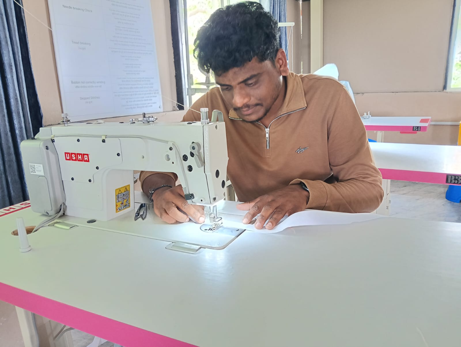
Below, I am showing how I stitched the support to the cover.
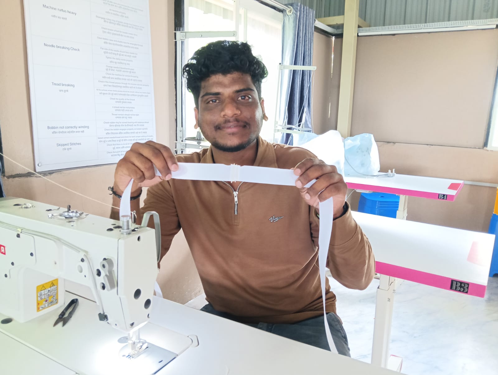
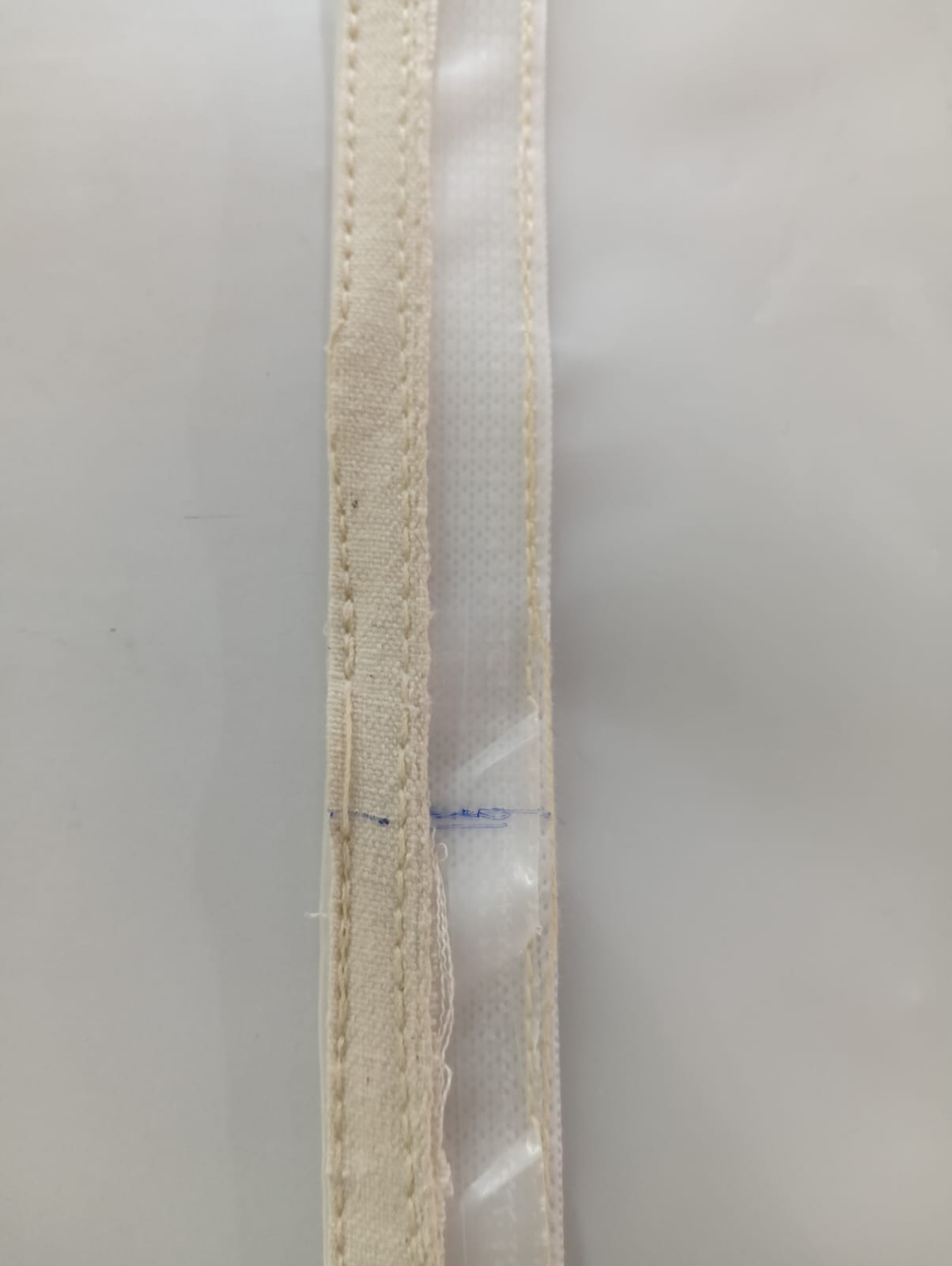
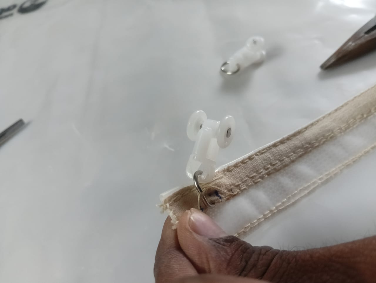
To hang the ring between the cover and the sliding mechanism, I used a piece of cloth. I folded it into three layers, created a strip of suitable size, and stitched it to the support.
Cutting the cloth into layers
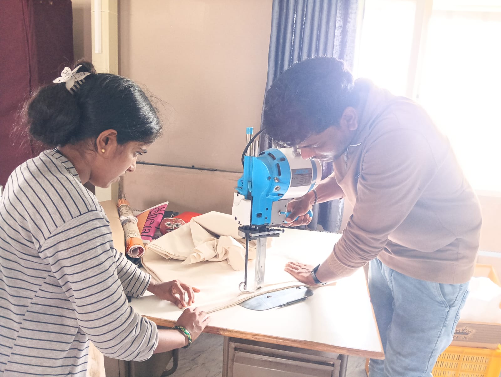
After cutting the layers, I stitched them into a strip. Below, I am showing the results."
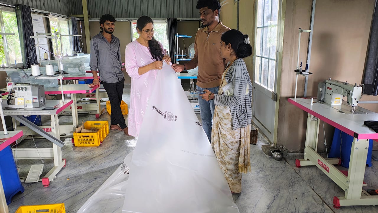
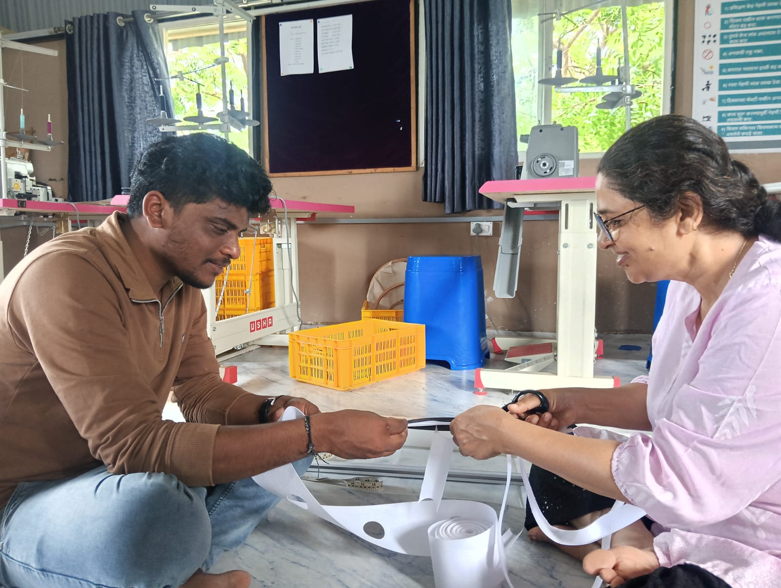
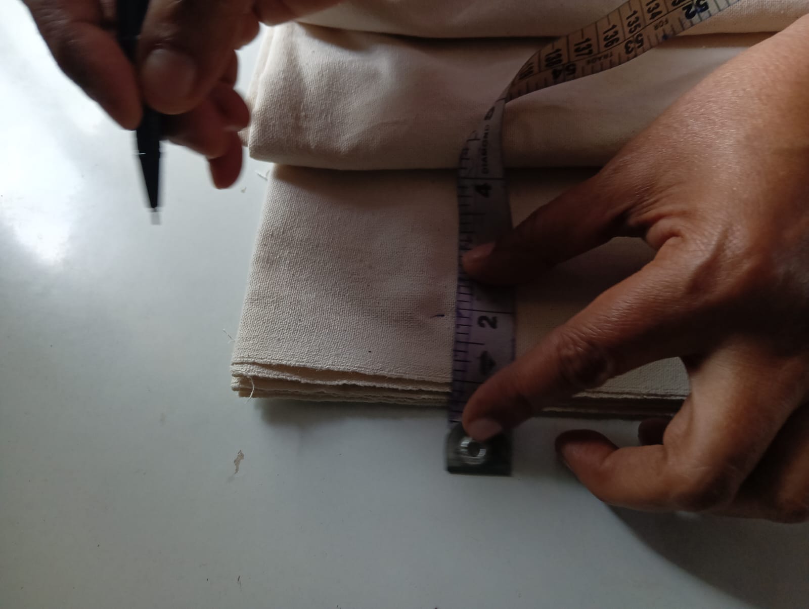
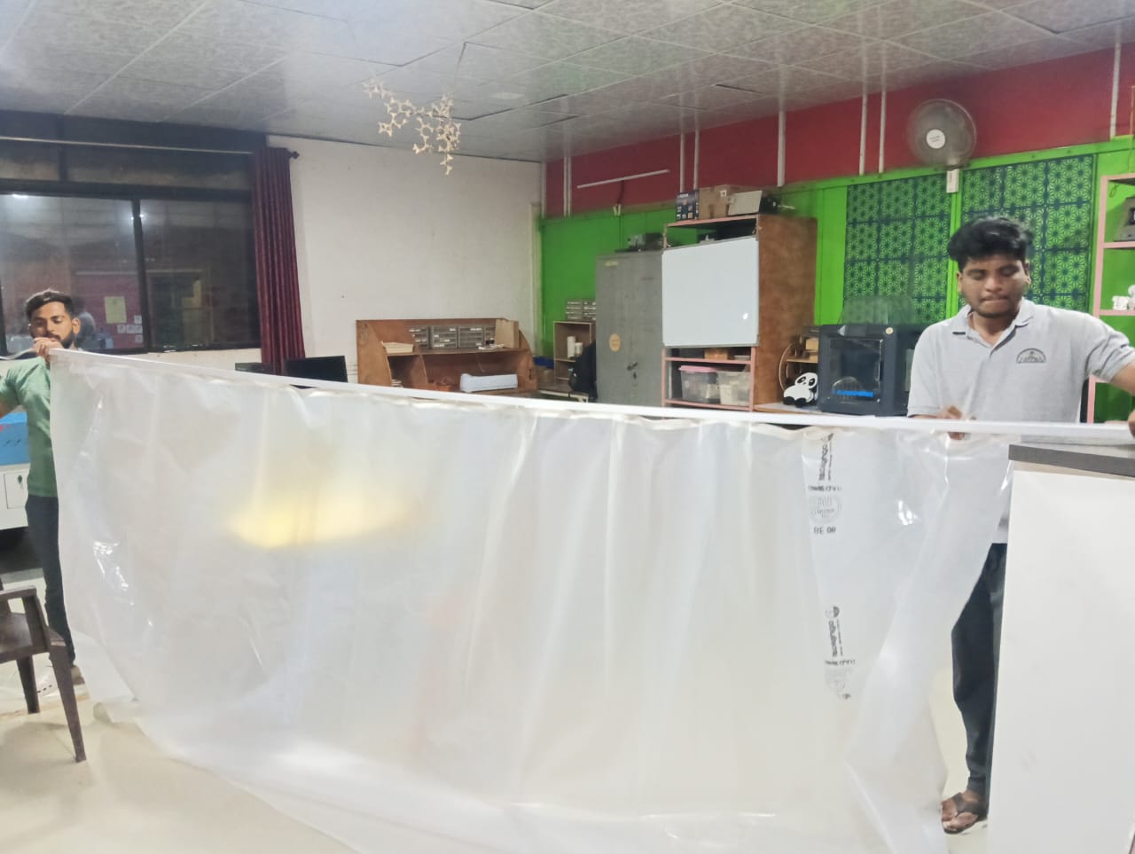
After that, I measured the distance between the rings for hanging. I marked the positions and created appropriate gaps to hang the rings on the sliding mechanism.
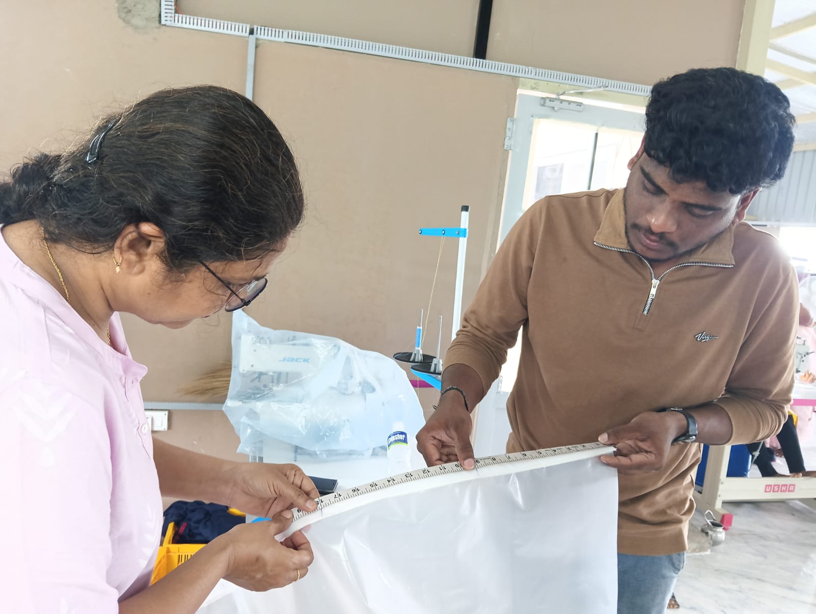
In the image below, Preyanka Madam and Sravini Madam are helping me prepare this process. Finally, my cover is ready for the mechanism
Assembling Process :
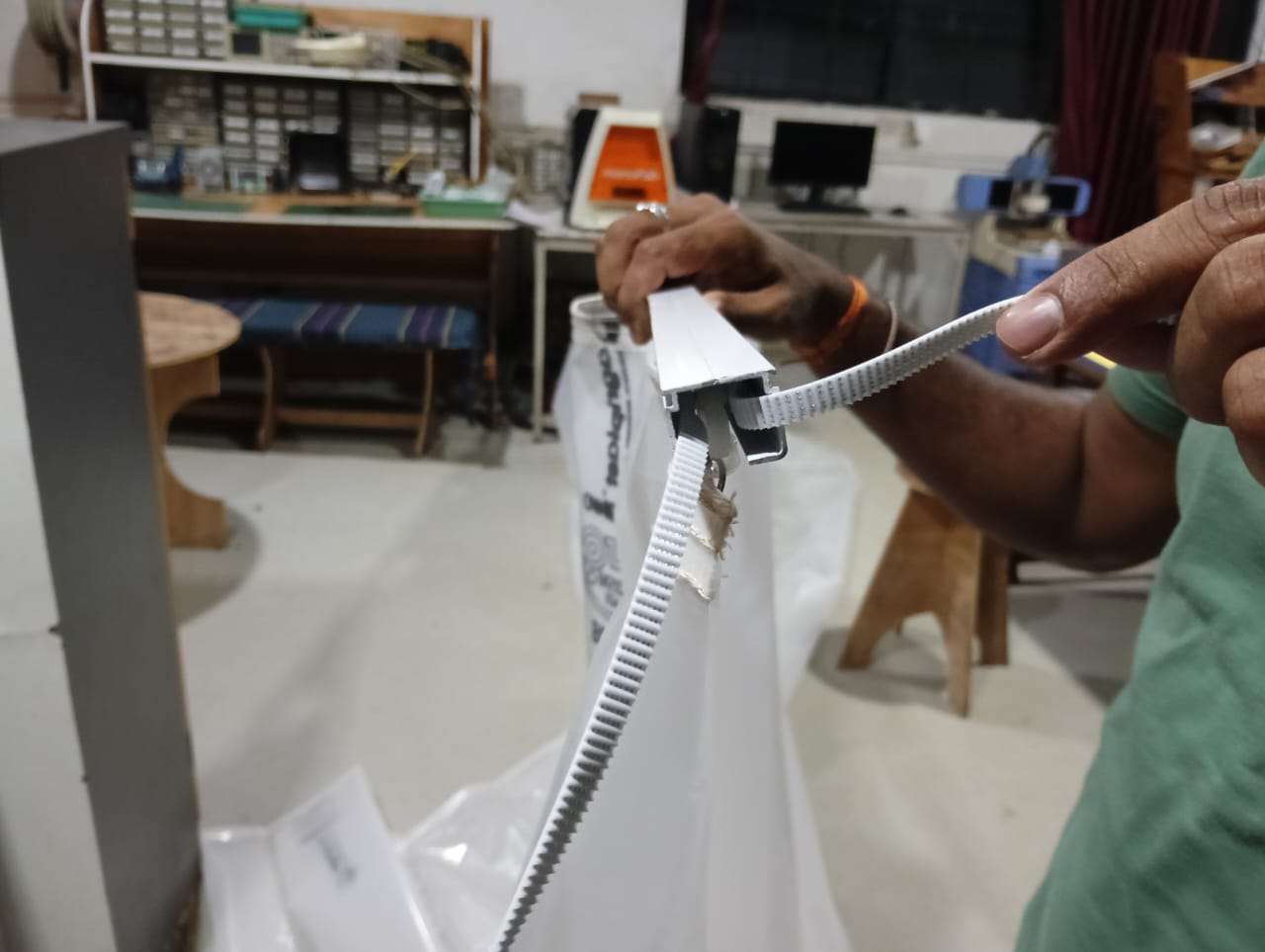
After completing the stitching, I started assembling the rollers onto the cover.
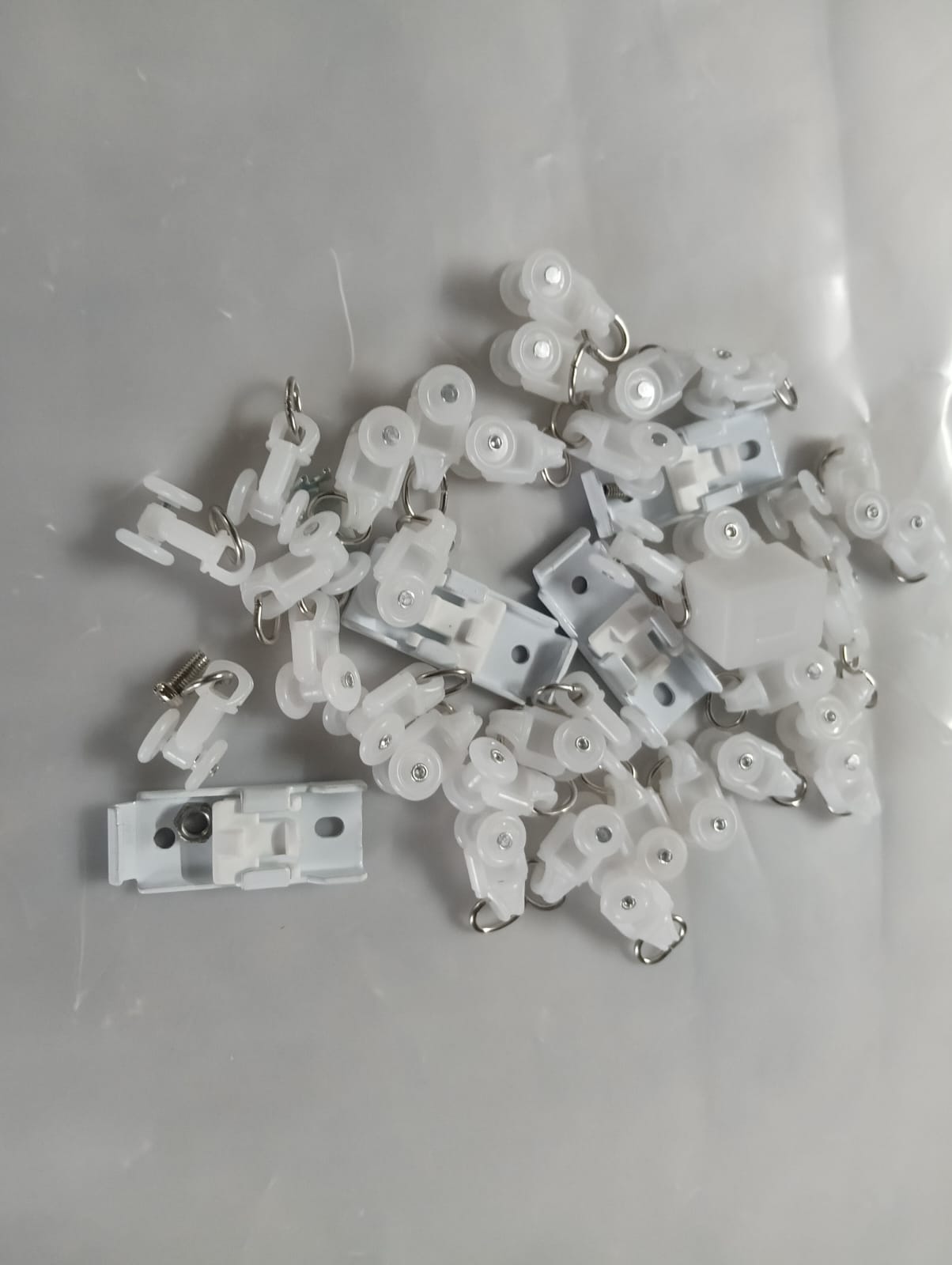
Fixing the rollers to the cover perfectly to ensure they do not come off.
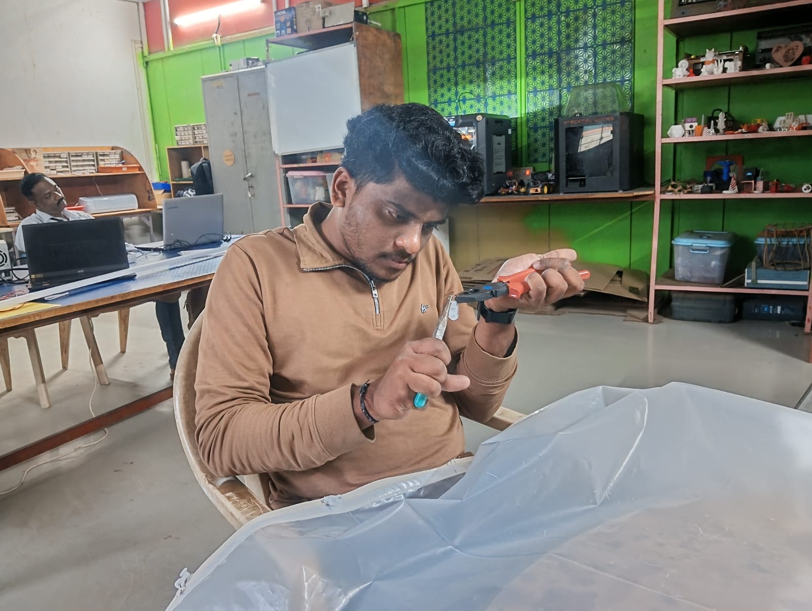
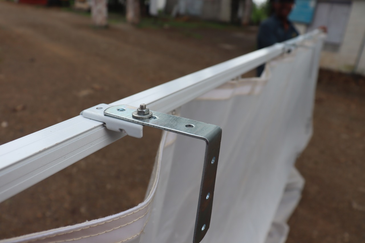
After fixing the rollers securely, I started assembling the cover onto the aluminum rail. This ensured smooth sliding and proper functionality of the mechanism
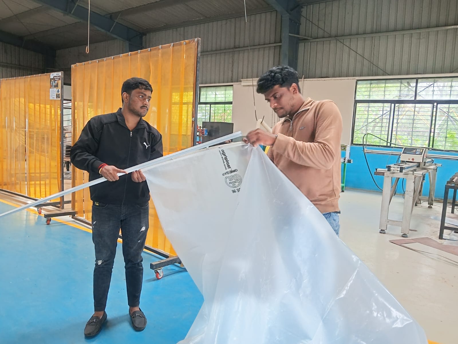
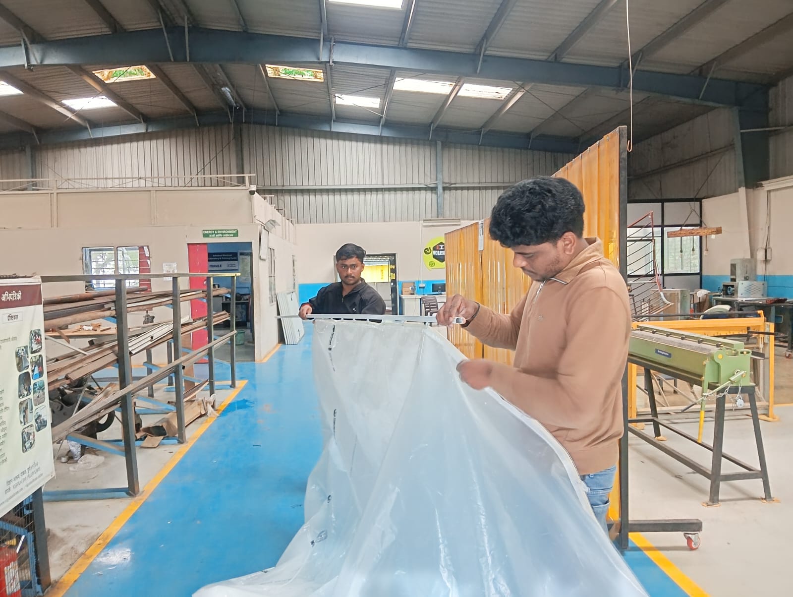
Below, I am showing how the cover is perfectly fitted into the rail.
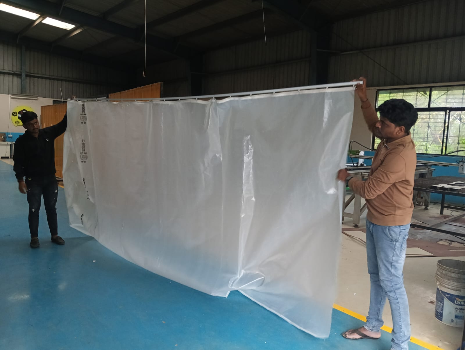
Mechanism Installation :
After confirming all the materials were ready, I started the installation of the mechanism. I am showing the process below.
Fixing the rollers and pulley.
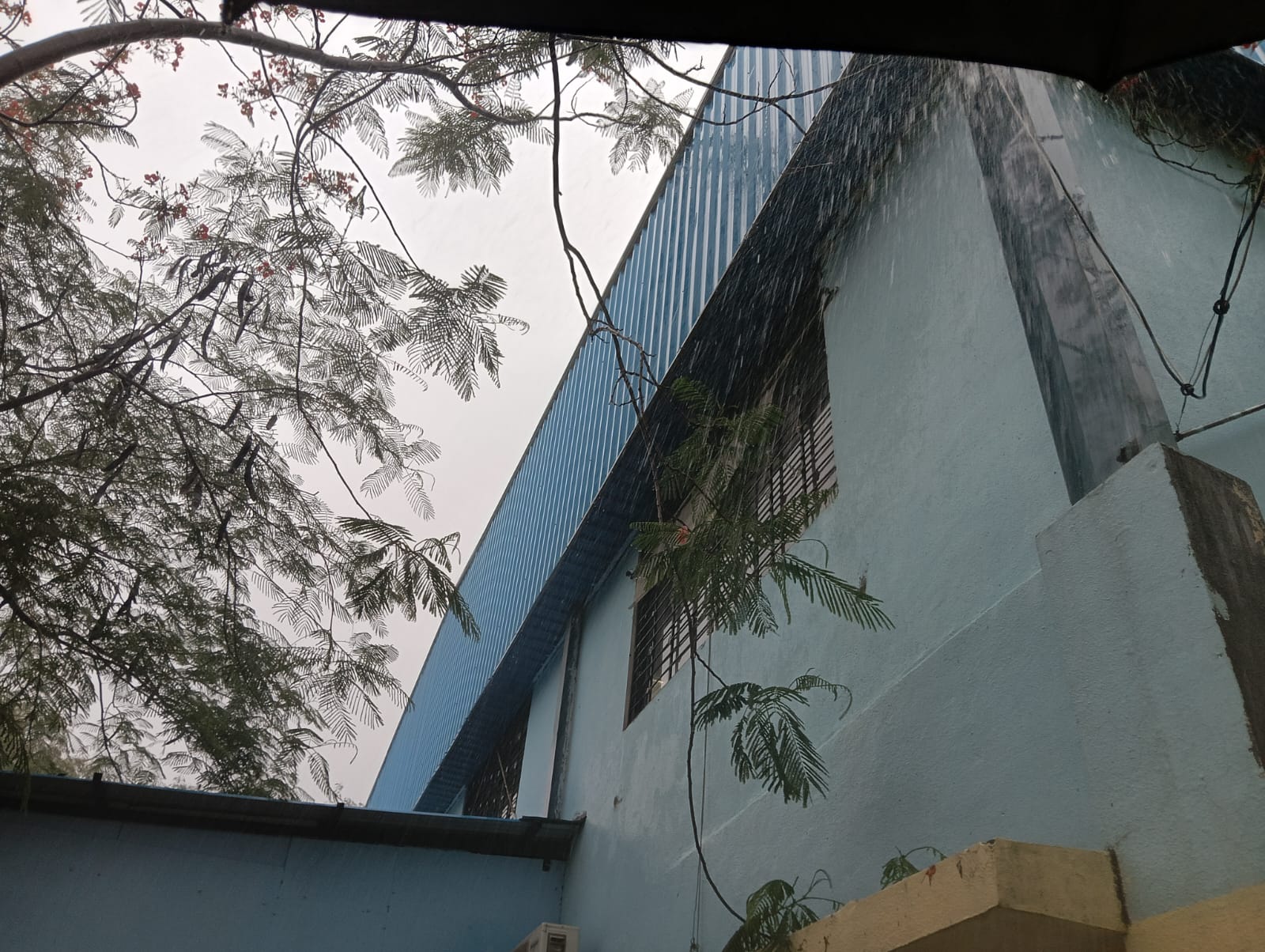
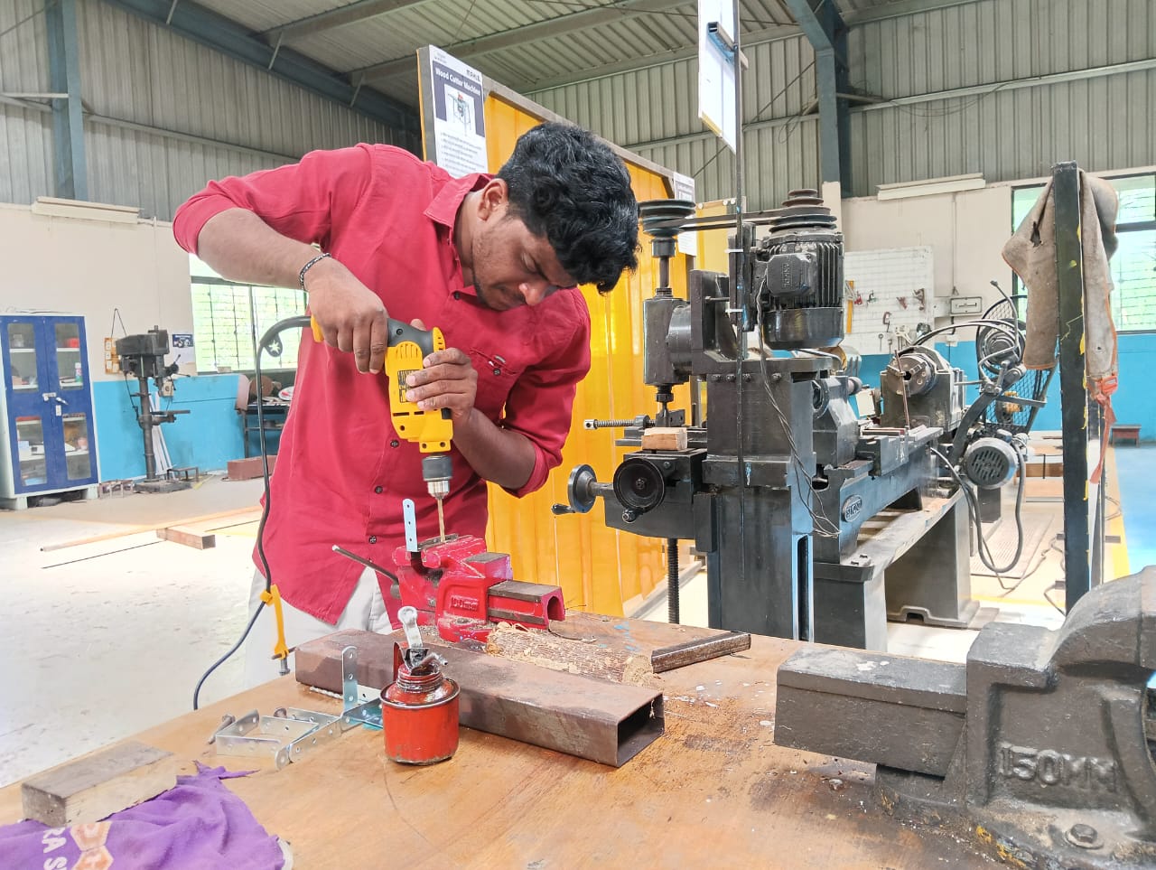
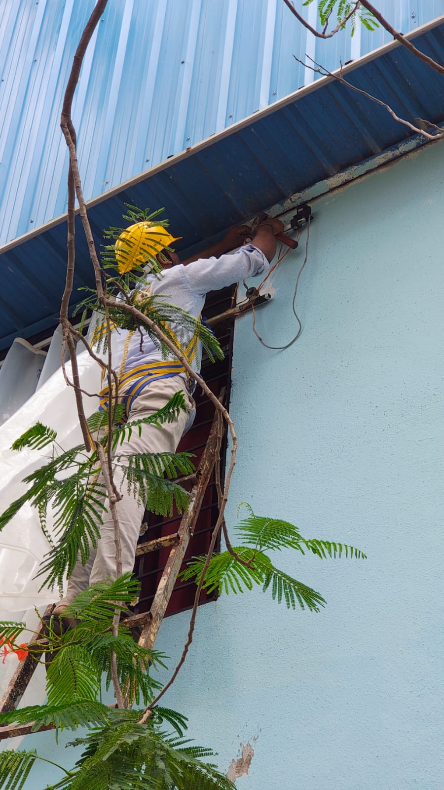
To fix the project to the window, some supports were needed. For that, I used L-shaped lamps and attached them to the wall.
Below, I am expanding the holes on the L-lamps for proper fixing, and I am also drilling the aluminum rail to mount the L-lamps securely.
I fixed the L-clamps to secure the project to the window.

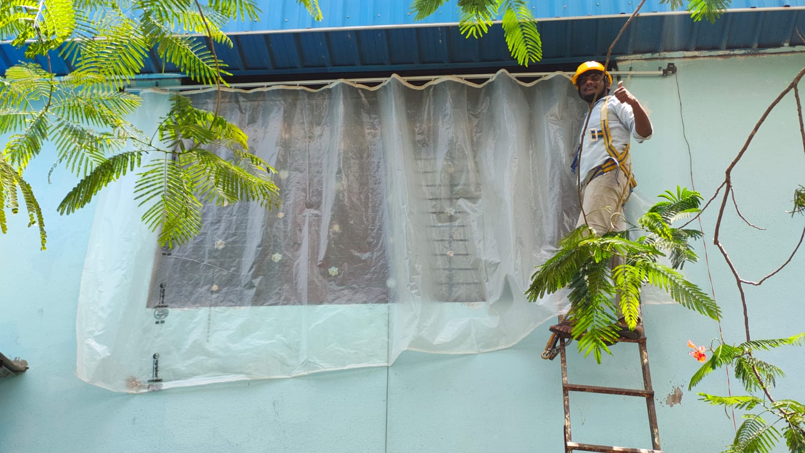
After fixing the supports, my project was ready to be installed, so I fixed it to the window with the help of my friends.
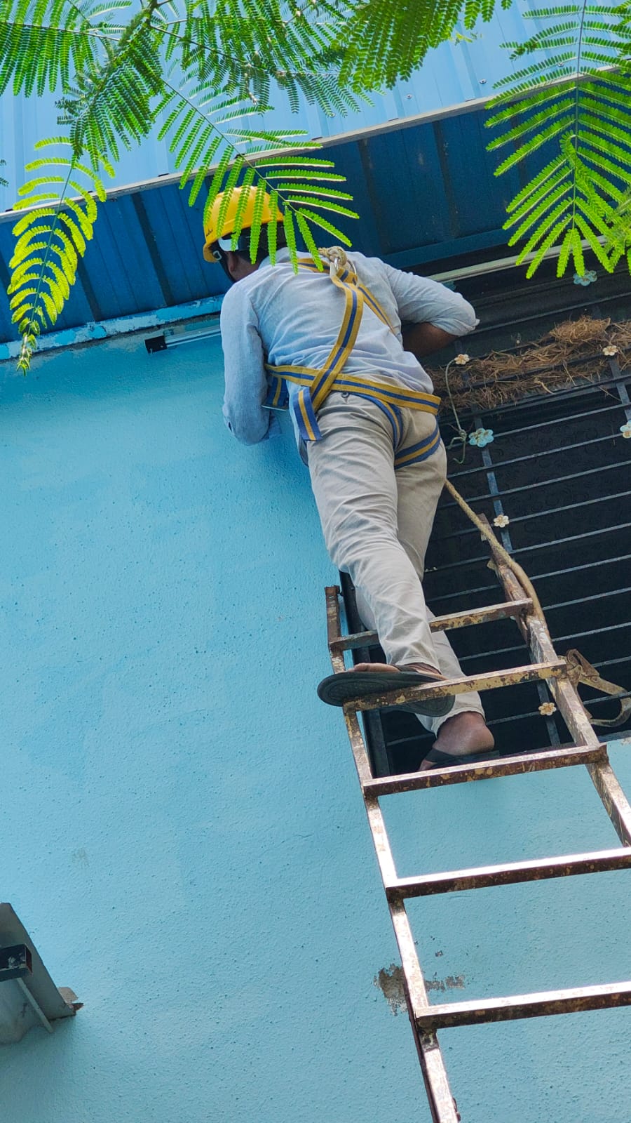
I successfully completed the installation of the project, so the problem in the Vigyan Ashram lab is now solved.
I worked on my final project from the beginning, but I mainly focused on it during the System Integration week. Click here to visit Week 15: System Integration.
Arduino Code: Final code for my final project
#define BLYNK_TEMPLATE_ID "TMPL3A2dSzj4j"
#define BLYNK_TEMPLATE_NAME "WiRain Cover"
#define BLYNK_AUTH_TOKEN "M2mQOfOl8IymuRJyODquSpzJK-ZbGkpN"

#include <WiFi.h>
#include <BlynkSimpleEsp32.h>
#include <AccelStepper.h>

// WiFi credentials
char ssid[] = "Extra";
char pass[] = "Ramesh@123";

// Stepper motor setup
#define DIR_PIN 9
#define STEP_PIN 10
#define MOTOR_INTERFACE_TYPE 1  // A4988

AccelStepper stepper(MOTOR_INTERFACE_TYPE, STEP_PIN, DIR_PIN);
const int totalSteps = 20000;
bool isMoving = false;

// Button pins
#define OPEN_BUTTON 2
#define CLOSE_BUTTON 3

void setup() {
  pinMode(OPEN_BUTTON, INPUT_PULLUP);
  pinMode(CLOSE_BUTTON, INPUT_PULLUP);

  stepper.setMaxSpeed(1000);
  stepper.setAcceleration(500);
  stepper.setCurrentPosition(0);  // Start closed

  Blynk.begin(BLYNK_AUTH_TOKEN, ssid, pass);
}

// Blynk handler: Open command (V0)
BLYNK_WRITE(V0) {
  if (!isMoving && stepper.currentPosition() != totalSteps) {
    stepper.moveTo(totalSteps);
    isMoving = true;
  }
}

// Blynk handler: Close command (V1)
BLYNK_WRITE(V1) {
  if (!isMoving && stepper.currentPosition() != 0) {
    stepper.moveTo(0);
    isMoving = true;
  }
}

void loop() {
  Blynk.run();

  // Move stepper if needed
  if (isMoving) {
    stepper.run();
    if (!stepper.isRunning()) {
      isMoving = false;
    }
  } else {
    // Handle buttons only when motor is idle
    if (digitalRead(OPEN_BUTTON) == LOW && stepper.currentPosition() != totalSteps) {
      stepper.moveTo(totalSteps);
      isMoving = true;
      delay(200);  // Debounce
    }

    if (digitalRead(CLOSE_BUTTON) == LOW && stepper.currentPosition() != 0) {
      stepper.moveTo(0);
      isMoving = true;
      delay(200);  // Debounce
    }
  }
}
Acknowledgement :
I would like to sincerely thank Prof. Neil and his team, Vigyan Ashram Director Mr. Yogesh Kulkarni Sir, and Deputy Director Mr. Ranajeet Shanbhag Sir for their invaluable support and guidance.
My heartfelt gratitude also goes to my Fab Academy instructors, Mr. Suhas Labade and Ms. Dipali Kambale, for their continuous mentorship. A special thanks to my Fab Academy colleagues for their collaboration and encouragement throughout the journey.
I would also like to thank Uemash and Arti Bhosale, as well as the workshop faculty, for their support and assistance.
Lastly, a very special thanks to Mr. Kishore Gaikwad Sir for standing by me and supporting me in every step of this journey.