Assignment 14: Interface and Application Programming
This week was a significant milestone for me because I have always wanted to develop apps but never had the opportunity or direction to start. Through this assignment, I began exploring different platforms and programming languages to create project-specific applications. I started working with MIT App Inventor to control an LED and an AC light. Additionally, I used Processing to create a graphical user interface (GUI) with five buttons to control an RGB LED via serial communication. These experiences helped me understand how to interface hardware with software in a meaningful and functional way. Although I encountered some challenges, especially in getting the serial communication to work correctly, I was eventually able to implement the RGB control as intended. This week boosted my confidence in app development and real-world interfacing.
Highlight Moments of the Week
Group Assignment Brief:
Objective of the Group Assignment
- Compare as many tool options as possible
For the purpose of this group assignment, we explored different application development tools such as MIT App Inventor, Processing, and Blynk 2.0. We compared each of these tools and discussed how we understood and used them.
1. Processing
Processing is a flexible, open-source graphical programming environment primarily used for visual arts, design, and creative coding. It’s built on Java and is widely appreciated for its simplicity and ease of use in creating visual content like animations, simulations, and interactive applications. Artists, students, and designers use Processing to bridge the gap between coding and creativity. It supports rapid prototyping and provides direct access to drawing functions, image processing, and interaction tools. One can easily integrate sensors and Arduino for interactive physical computing projects. It has a vibrant community and a vast number of examples to learn from. Processing promotes learning to code within a visual context, making it perfect for beginners. It supports exporting projects to applications or Java applets. Overall, it empowers users to express logic through art and visuals effortlessly. for More information
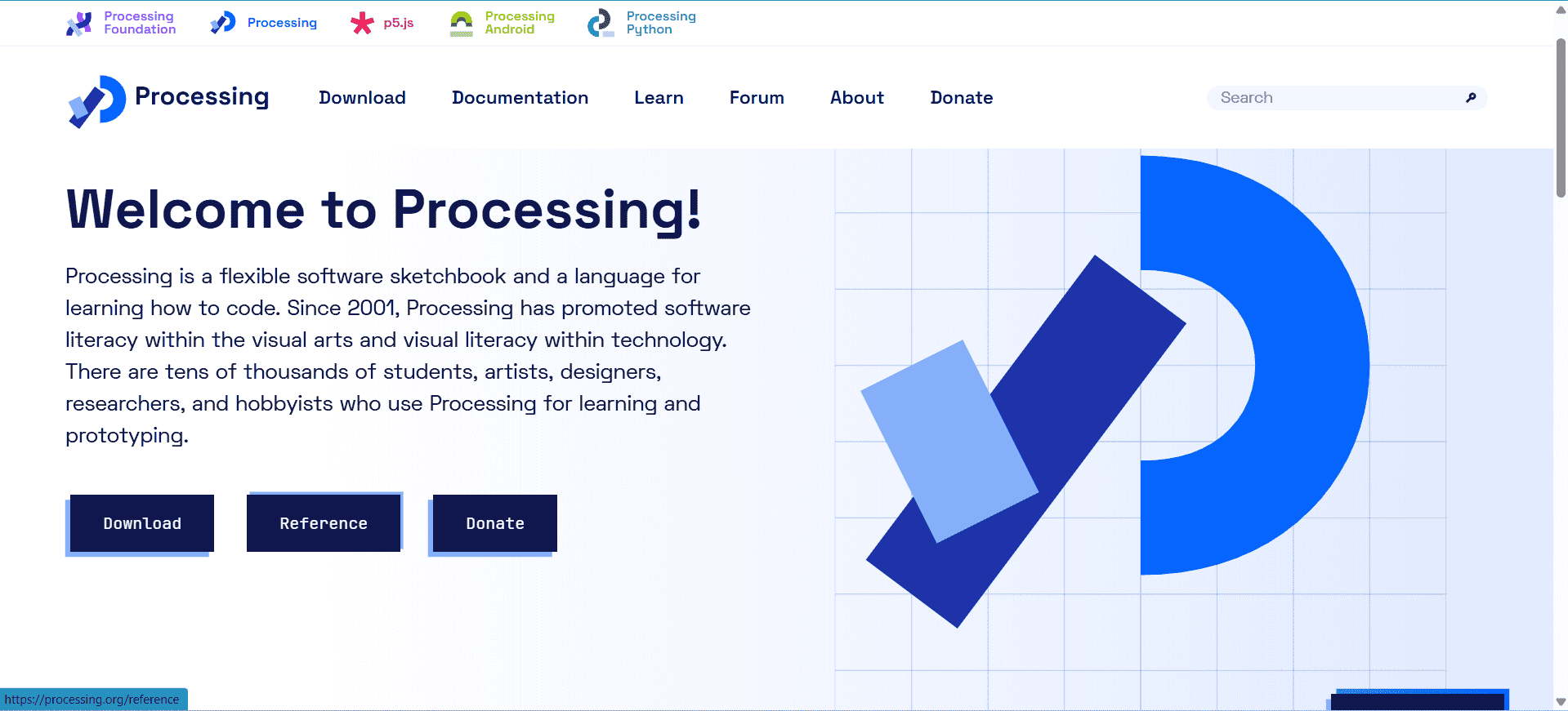
If you want to download the Processing software please click here.
2. MIT App Inventor
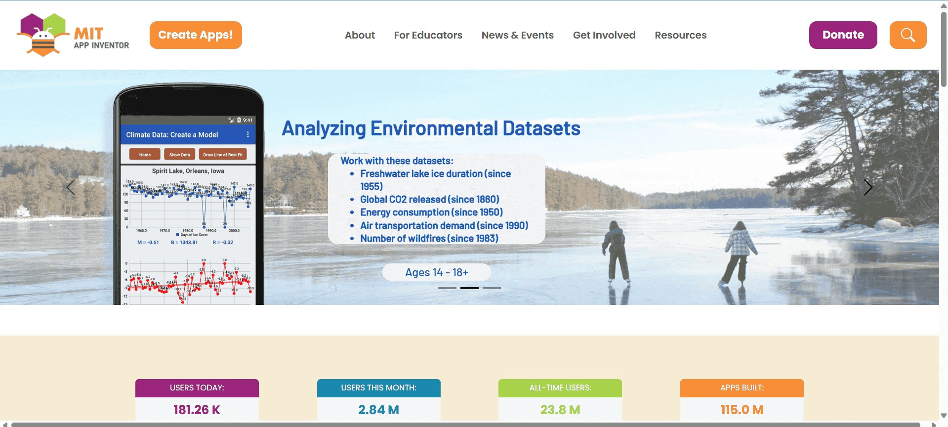
MIT App Inventor is a user-friendly, web-based platform for building Android applications without traditional coding. It uses a drag-and-drop interface with visual blocks that represent code logic, making it ideal for beginners and educators. App Inventor allows users to quickly create interactive mobile apps with access to sensors, media, and connectivity tools like Bluetooth and the internet. It's particularly useful in educational environments where students learn programming concepts through practical mobile projects. The platform supports real-time testing of apps on connected Android devices. It simplifies complex functionalities like database storage and web communication into manageable visual components. App Inventor has strong community support and extensive documentation for guidance. It promotes logical thinking and innovation, especially for those new to mobile development. Overall, it’s a powerful gateway into app development for learners and hobbyists. for More information
If you want to visit the site please click here.
3. ThingSpeak
ThingSpeak is an IoT analytics platform that allows users to collect, store, and analyze sensor data in the cloud. It is widely used in projects where devices send data like temperature, humidity, or gas readings to an online channel for visualization and processing. ThingSpeak supports communication using HTTP and MQTT protocols, making it easy to integrate with ESP32, Arduino, and other microcontrollers. One of its key features is real-time data plotting, which helps monitor system behavior remotely. It also supports MATLAB integration for advanced data analysis and automation. Users can create public or private channels for their projects and even set up alerts or actions based on conditions. It’s very useful in agriculture, environmental monitoring, and smart home projects. ThingSpeak provides dashboards that are customizable and informative. Overall, it’s an efficient tool for managing IoT data without building a backend from scratch. for More information
 ]
]
If you want to visit the site please click here.
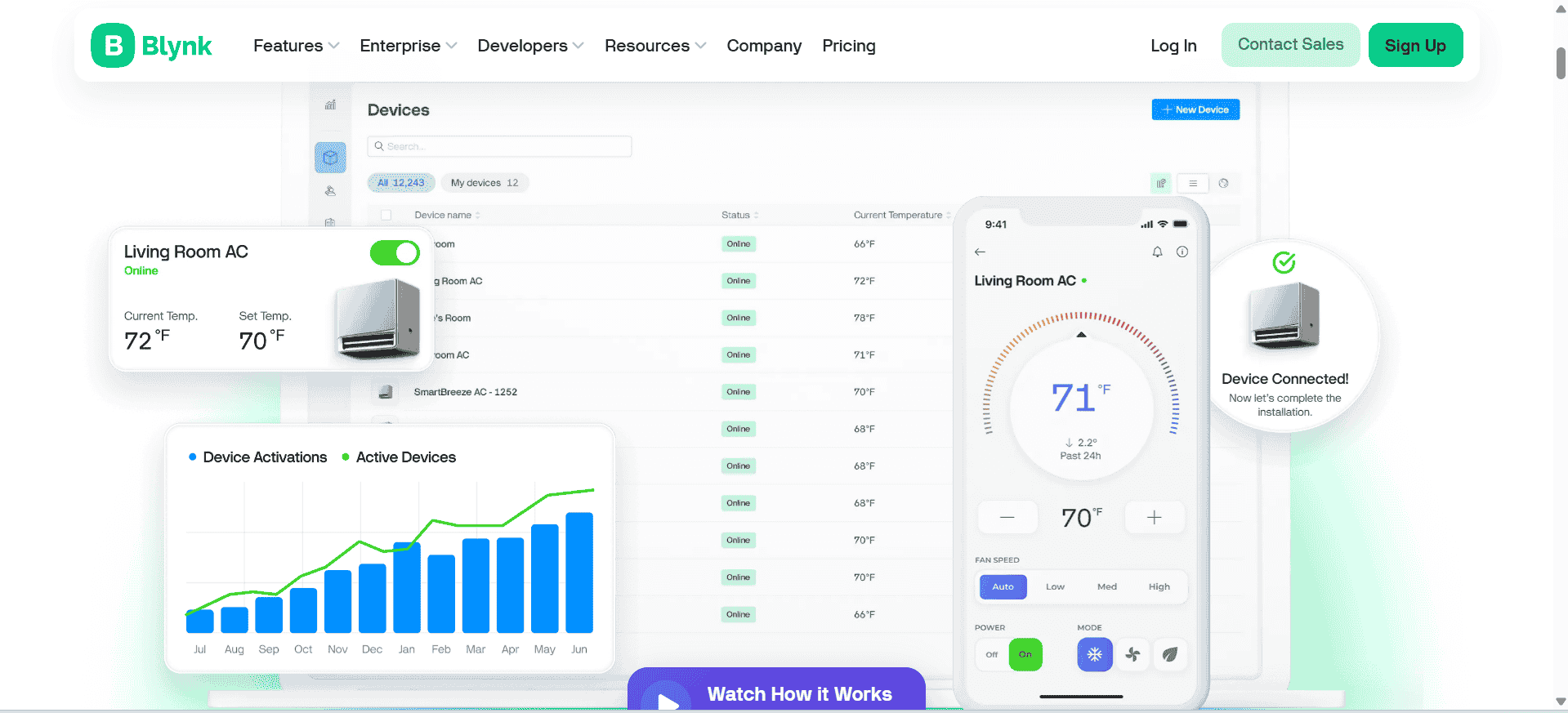
4. Blynk
Blynk is a platform that allows developers to build smartphone apps to control hardware like Arduino, ESP32, and Raspberry Pi over the internet. It uses a drag-and-drop interface to create virtual dashboards with buttons, sliders, graphs, and other widgets that connect directly to IoT devices. Blynk makes real-time control and monitoring of devices very simple, even for non-programmers. It supports communication through Wi-Fi, Bluetooth, and cellular networks. With its Blynk.Cloud service, users can deploy and manage projects remotely with little configuration. The platform also allows users to write automation rules, schedule tasks, and get notifications based on data inputs. Blynk’s cross-platform compatibility ensures access through Android, iOS, and the web. It is ideal for quick prototyping, smart home systems, and automation tasks. Overall, Blynk provides a user-friendly yet powerful way to interact with embedded devices from anywhere. for More information
If you want to visit the site please click here.
Individual Assignment
Objective of the Individual Assignment:
- Write an application that interfaces a user with an input &/or output device that you made.
Before starting the individual assignment, I want to explain how I began working on it. Initially, I decided to control an LED using the ESP32-C3 Xiao with MIT App Inventor. However, I faced an issue, which I have explained at the end of this assignment. After gaining clarity on the problem, I decided to use the same MIT App to control an LED with an ATtiny microcontroller using the HC-05 Bluetooth module. Later, I used the Processing software to control an RGB LED. The steps I followed to complete this are explained below, step by step.
1. APP Development Using MIT App Inventor :
As the first outcome of this assignment, I developed an Android app using MIT App Inventor. This app sends commands via Bluetooth, and based on the received commands, the controller performs the corresponding actions. In the MIT App, I created a simple interface with just two buttons: one to turn the LED ON and another to turn it OFF. The step-by-step process of how I built this app is explained below.
1a. Designing an Android App Using MIT App Inventor:
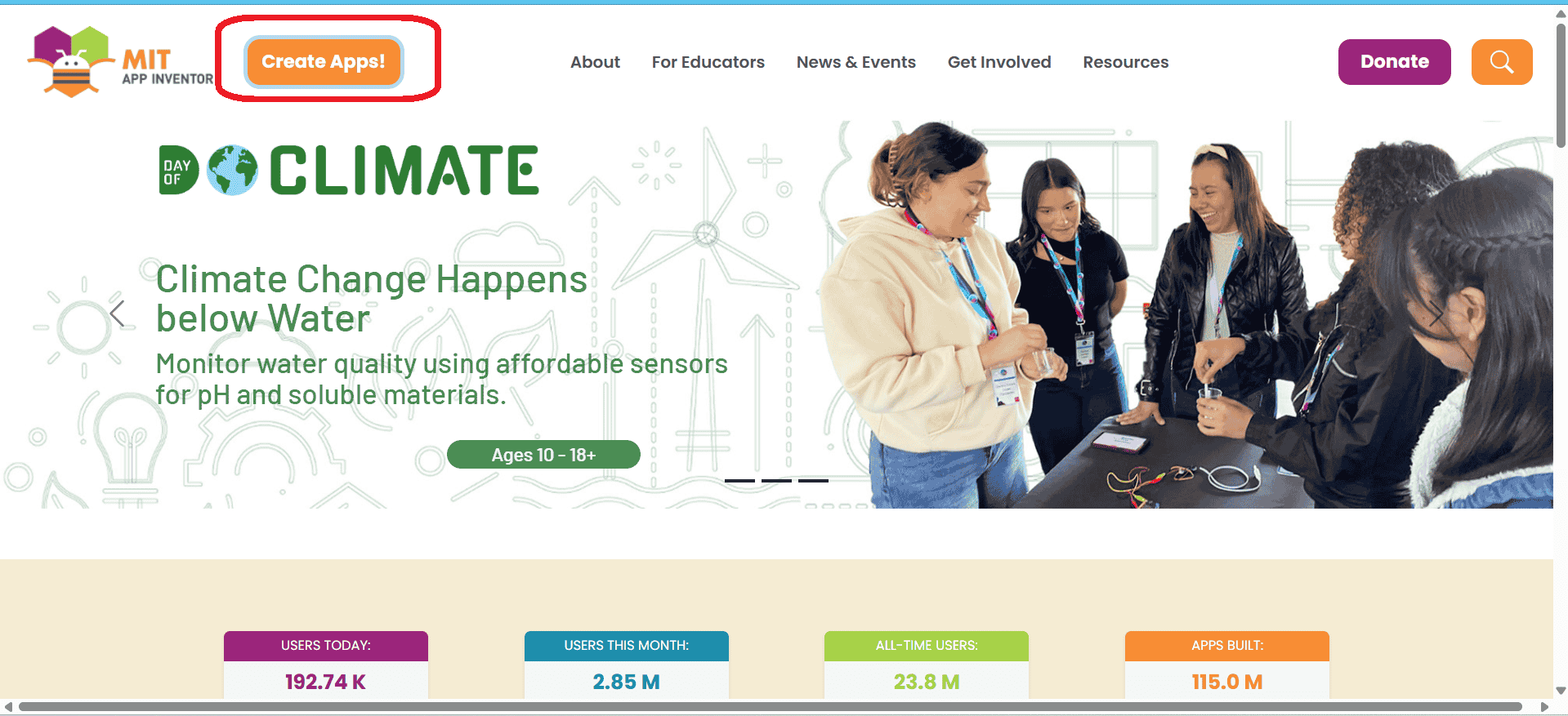
To design the MIT App, I first visited the MIT App Inventor website and clicked on “Create Apps.” After logging in with my Google account, I started a new project and gave a name to my app, as shown below.
If you want to visit the site please click here.
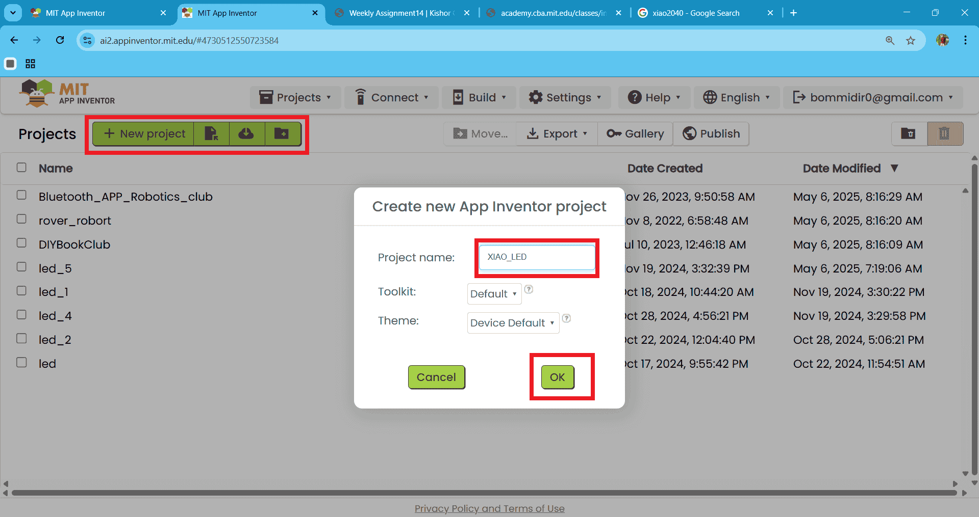
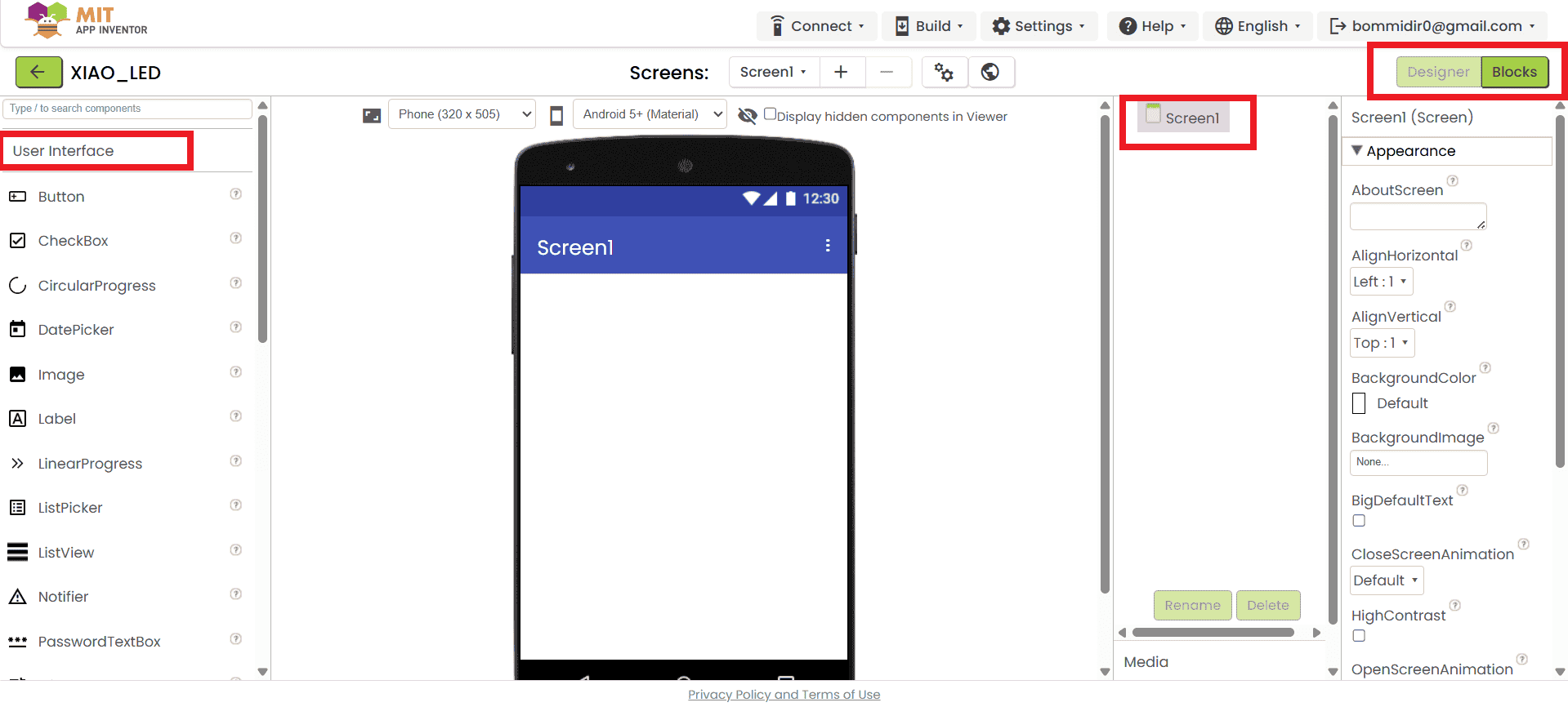
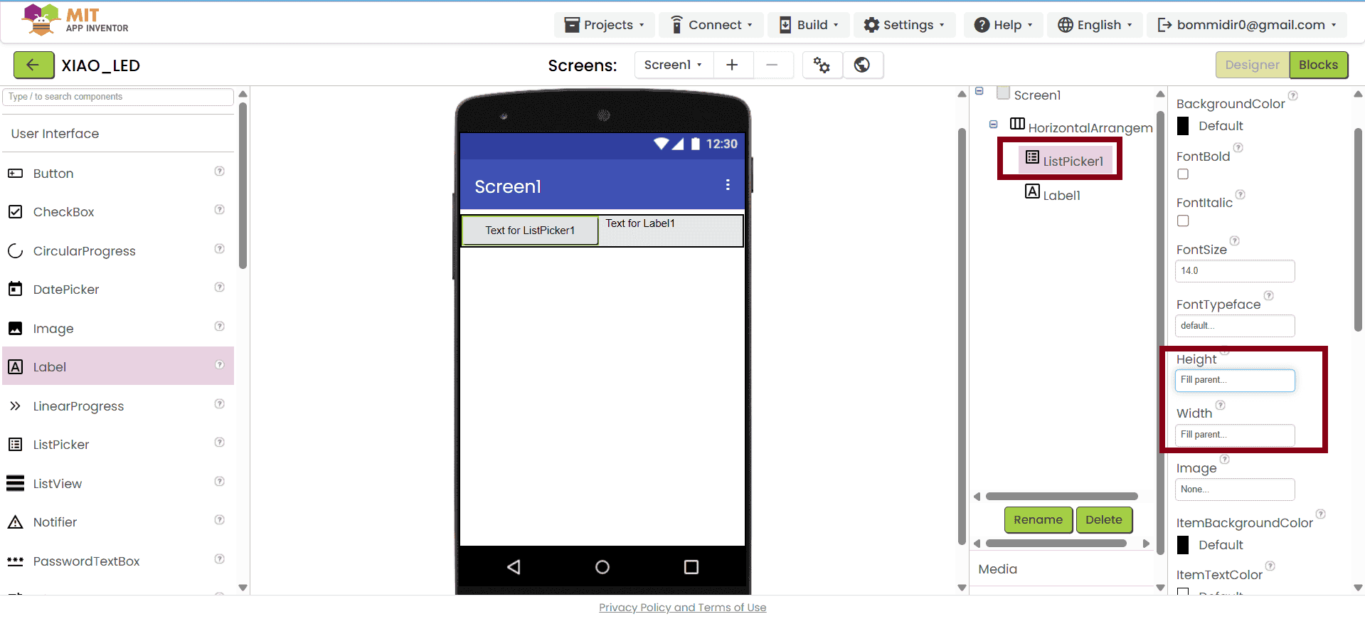
After clicking the "OK" button, the mobile screen interface automatically opens. In this screen, you can design the app according to your requirements. I designed the layout as shown below. From the "User Interface" section, I added buttons and other necessary components. On the right side of the screen, you can adjust properties such as height, color, and text for each element. The final design is shown in the image below.
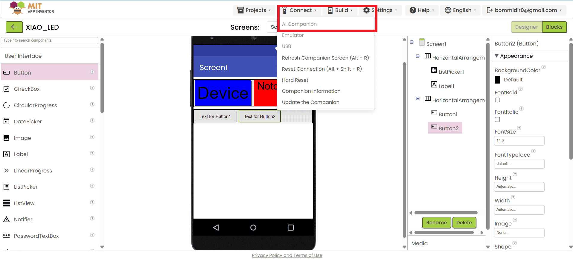
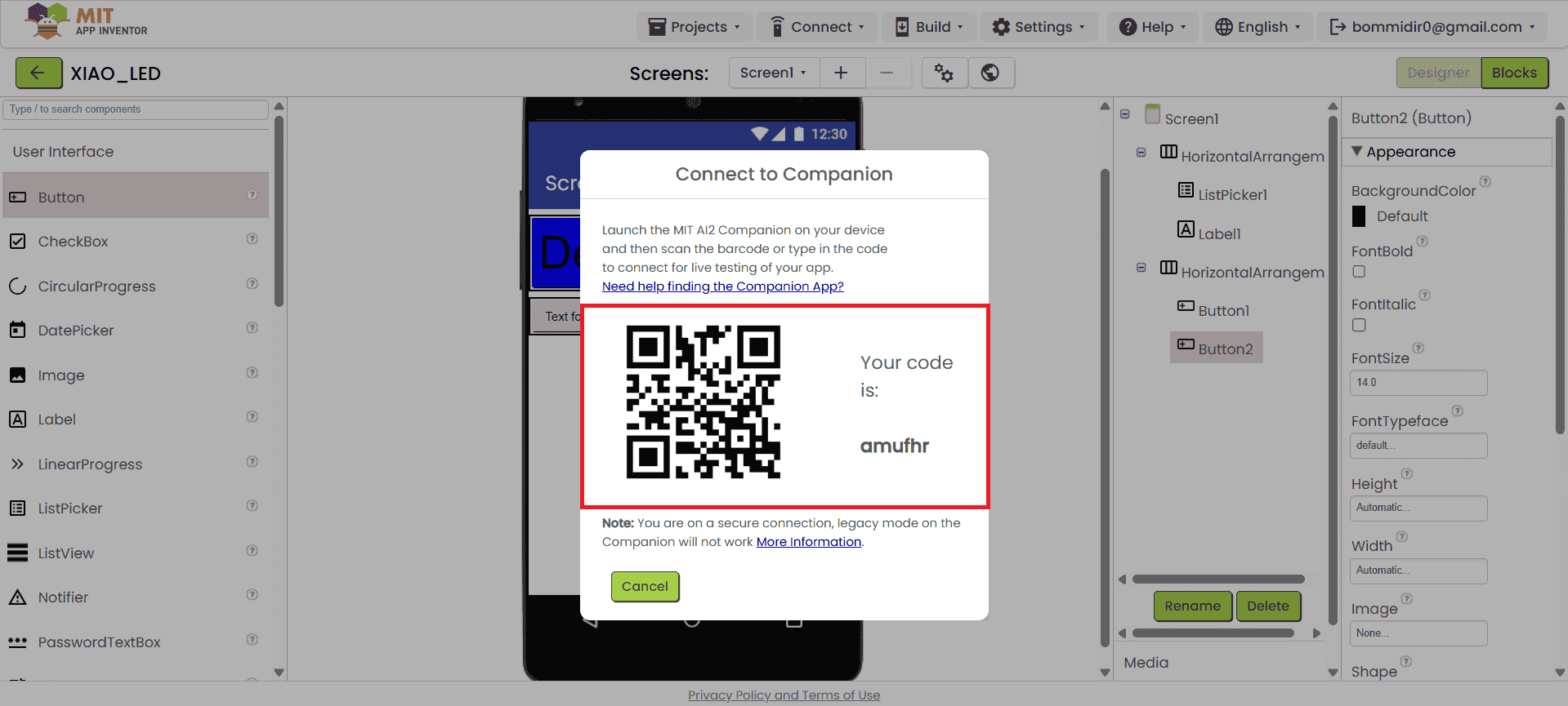
We also checked the app using the Live Companion feature on our mobile. I connected my phone using the AI Companion by scanning the QR code shown in MIT App Inventor. This helped me test whether the app was working properly or not on the mobile device.
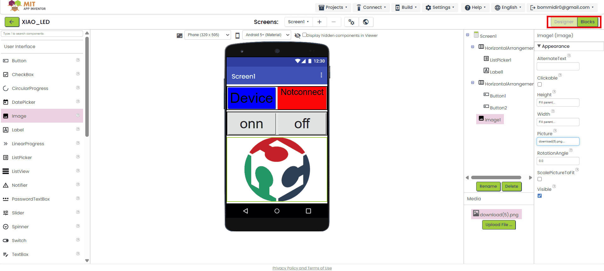
I successfully designed the front page of my app. After arranging all the user interface components, I clicked on the “Blocks” section, as shown below. In this section, we need to add the logic or program for the buttons placed on the front page. Below, I have shown how I added the blocks to control the functionality of each button.
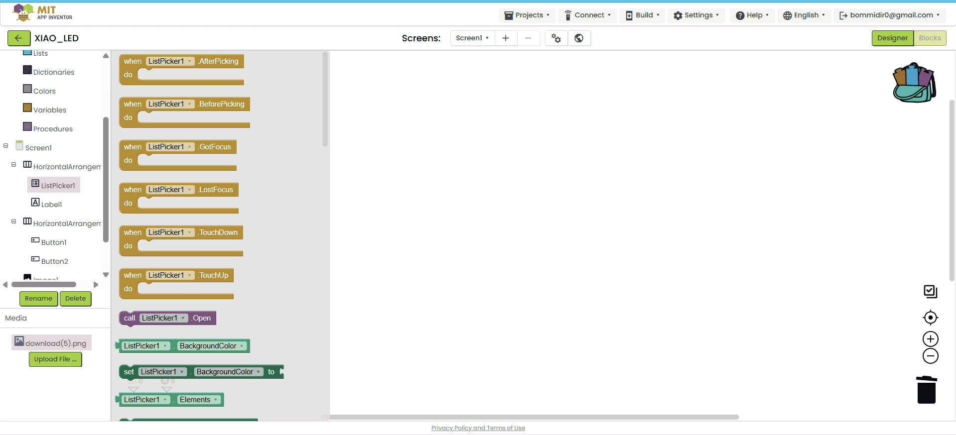
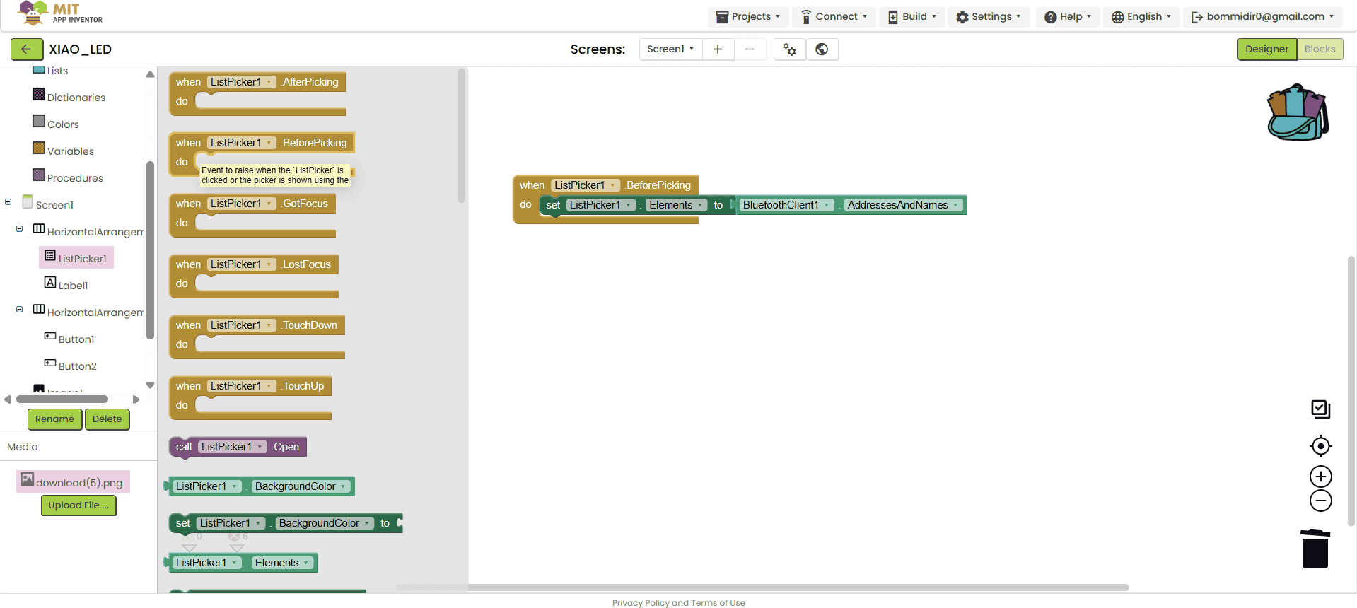
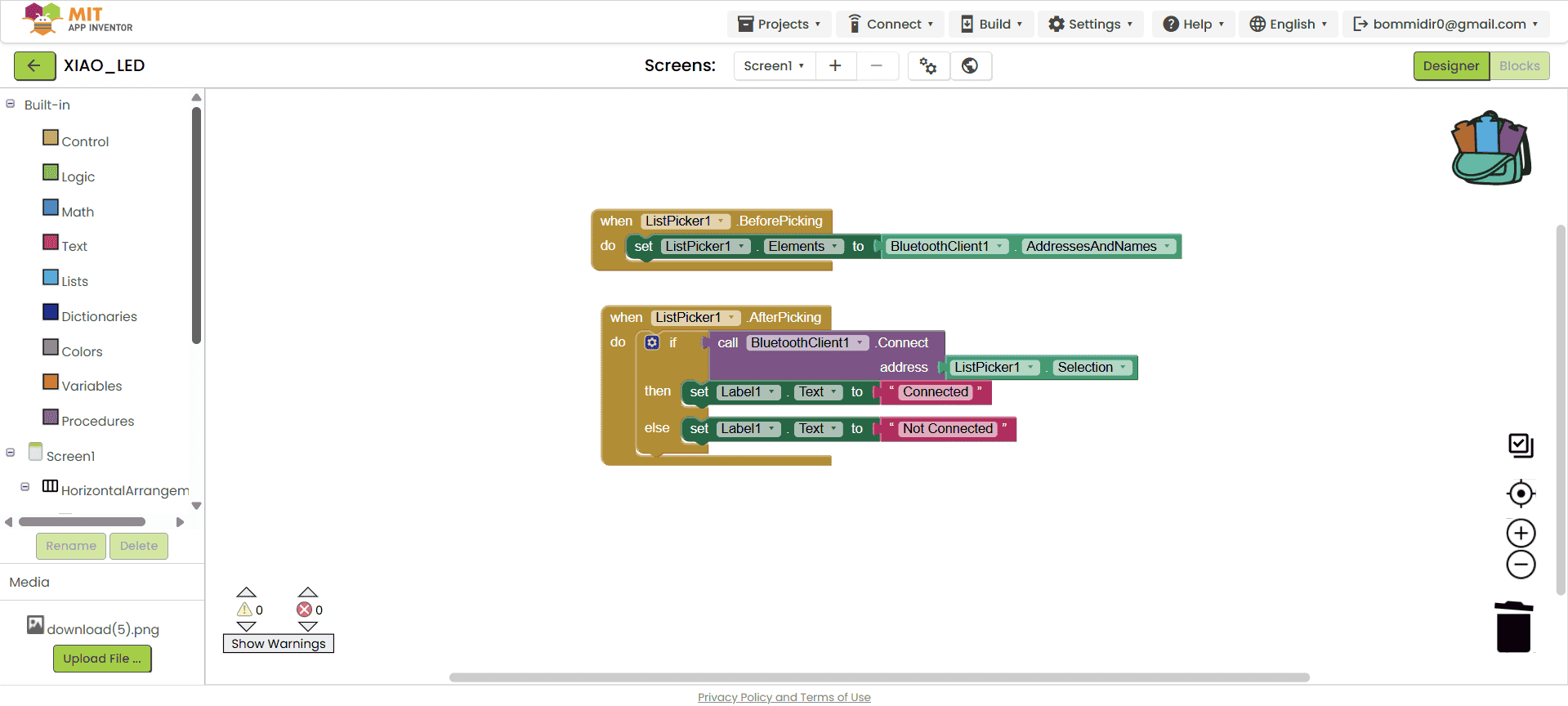
Below, I am showing how I added the blocks for the Bluetooth client. First, I used the “BeforePicking” block to display the list of available Bluetooth devices when the user clicks on the list picker. After that, I used the “AfterPicking” block to connect the app to the selected Bluetooth device.
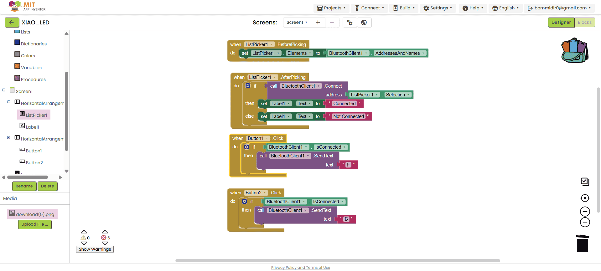
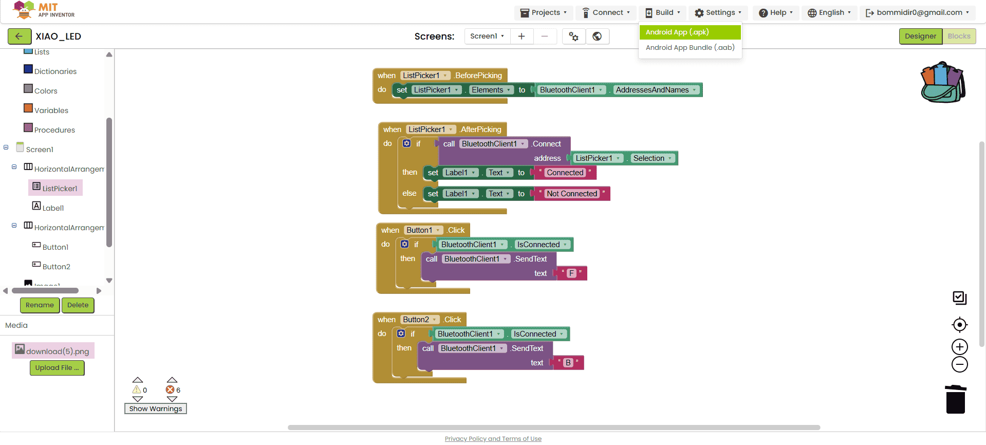
After completing the block coding for the Bluetooth client, I started adding blocks for the buttons. For the ON button, I assigned the command "F", and for the OFF button, I assigned the command "B". Once the block coding was completed, I proceeded to download the app. To do this, I clicked on the "Build" option and selected "Android APK", as shown in the image below.
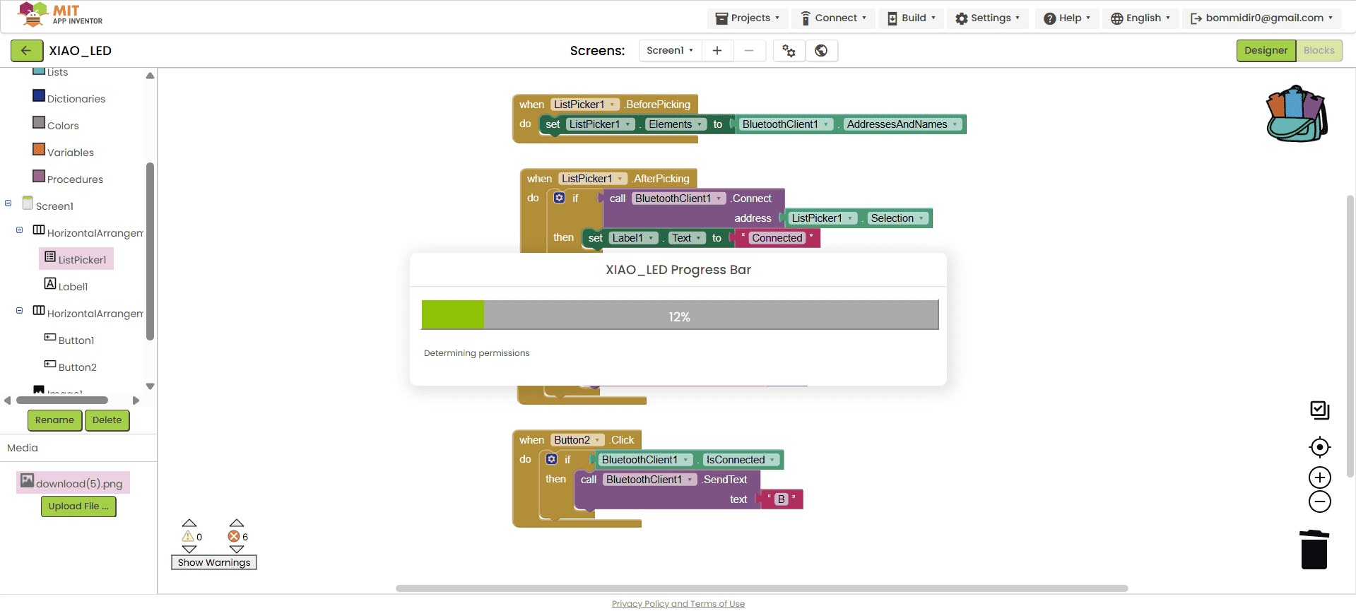
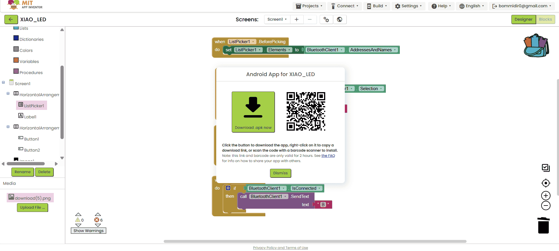
After clicking on "Android APK", the app starts building and the download process takes some time. Once the process is complete, the screen shows two options: on one side, a QR code is displayed, and on the other side, there is a direct APK file download link. You can choose either option based on your preference.
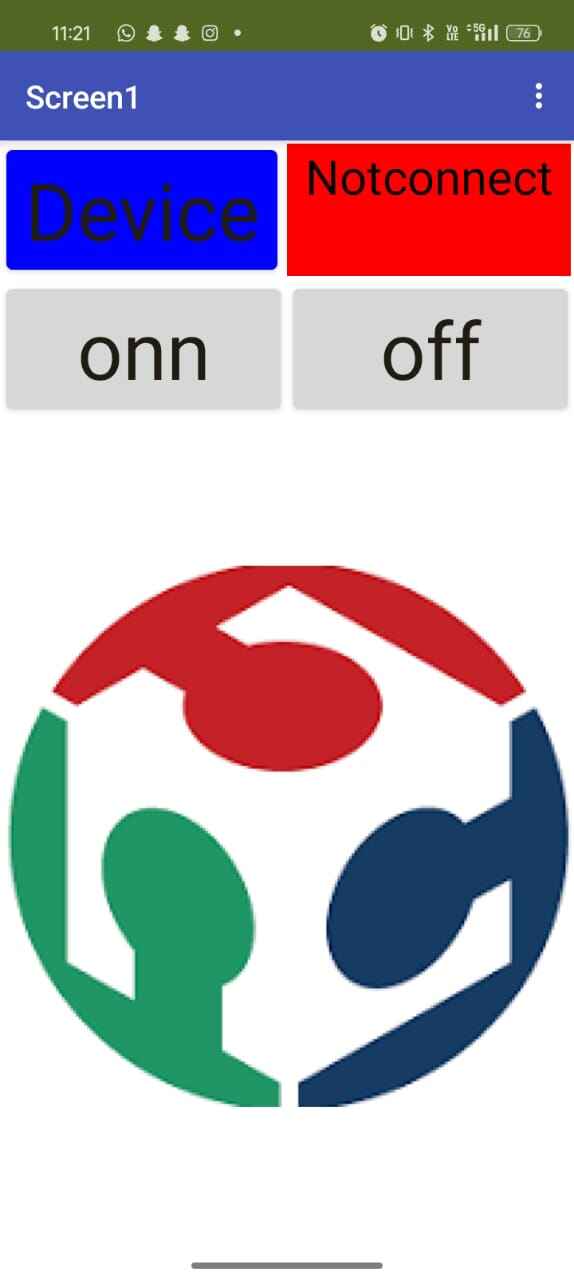
After successfully downloading the app to my mobile device, the app appeared as shown below.
Note: During the download and installation process, the app may ask for necessary permissions, which must be allowed for the app to work properly.
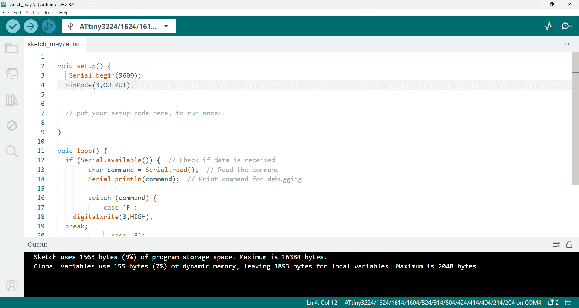
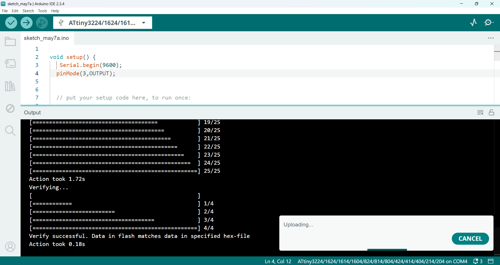
1b. Arduino code to control an LED:
To check if the app was working properly, I decided to test it with an LED. For this, I started writing the code in the Arduino IDE, as shown in the image below.
Below, I am showing how I connected the HC-05 Bluetooth module to the ATtiny microcontroller.
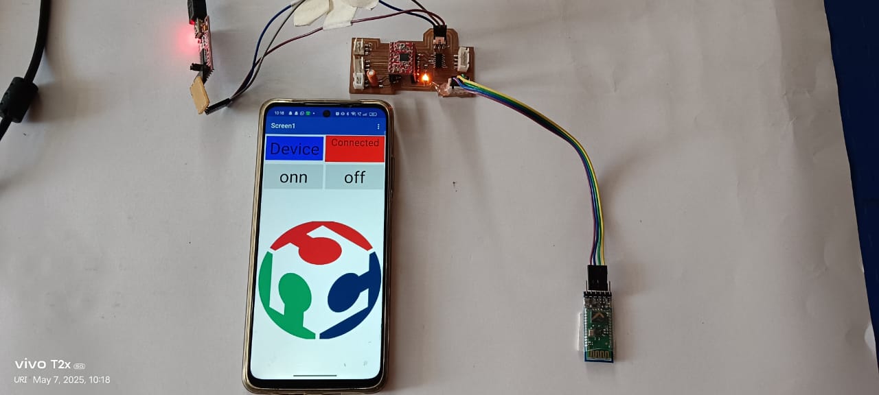
Below, I am showing the working video. Here, I connected the HC-05 module to the ATtiny microcontroller, as I explained at the beginning. I am controlling the LED, which is already connected to pin number 3.
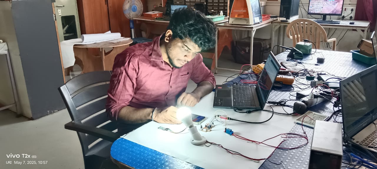
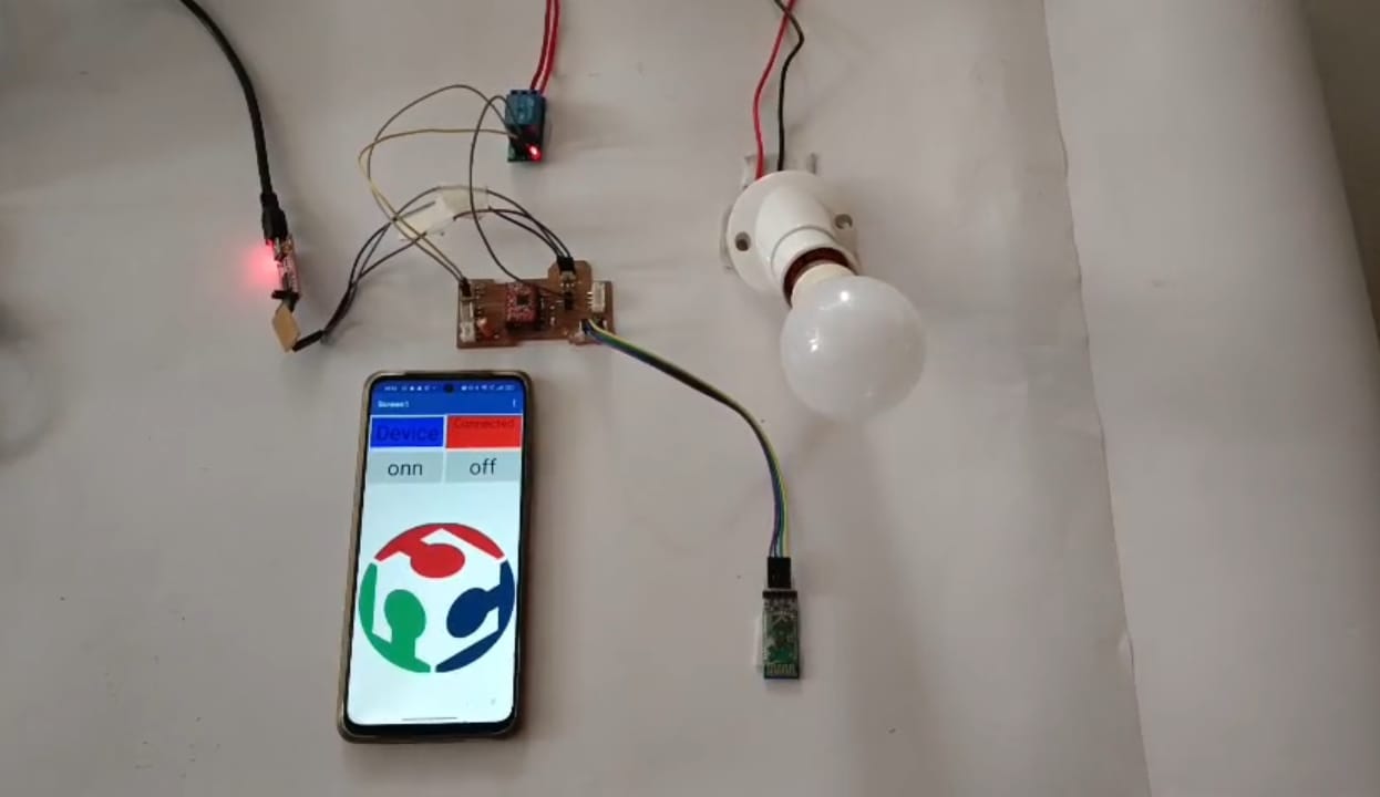
After successfully turning the LED on and off, I decided to control an AC appliance as well. To do this, I connected an electric bulb using a relay module. I used the same MIT App to control both the LED and the AC bulb. With this setup, I was able to operate both devices at the same time through Bluetooth. This experiment showed that the app is capable of controlling multiple devices simultaneously using a single interface. Below, I am showing the working video of this setup.
Arduino Code: Controlling LED Using MIT App
void setup() {
    Serial.begin(9600);
   pinMode(3,OUTPUT);
   pinMode(8, OUTPUT);
   digitalWrite(8, HIGH);

   // put your setup code here, to run once:

 }

 void loop() {
   if (Serial.available()) {  // Check if data is received
         char command = Serial.read();  // Read the command
         Serial.println(command);  // Print command for debugging

         switch (command) {
             case 'F':
     digitalWrite(3,HIGH);
     digitalWrite(8, LOW);
   break;
               case 'B':

   digitalWrite(3,LOW);
   digitalWrite(8, HIGH); break;

   delay(10);
 }
   }}
2. Controlling an RGB LED On/Off with Processing:
2a. Creating Buttons for Controlling RGB LED:
I also successfully controlled an RGB LED using Processing. To do this, I followed the steps below:
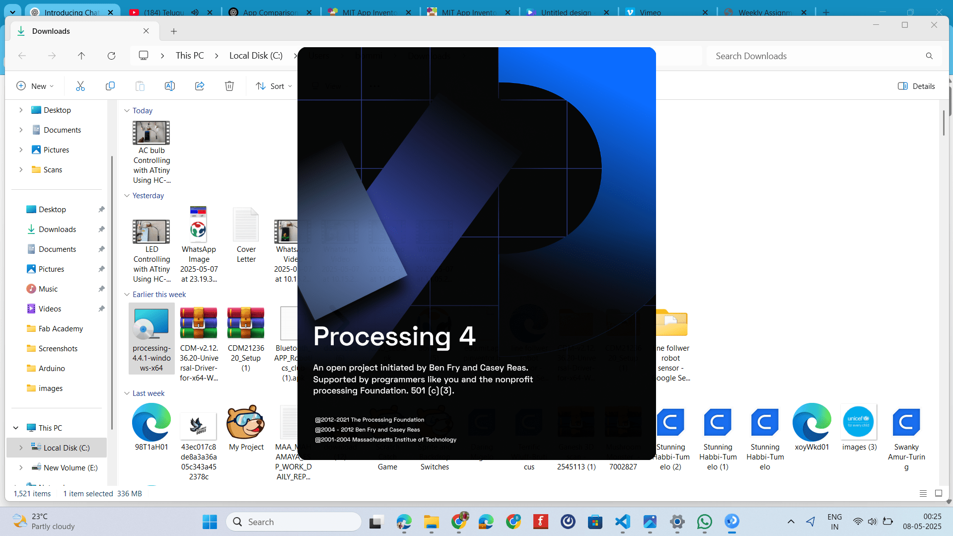
First, I downloaded the Processing software and installed it, as shown in the image below.
I opened the software and began writing the program using Java. This allowed me to control the RGB LED with Processing by sending signals to adjust the LED's colors based on the commands from the program.
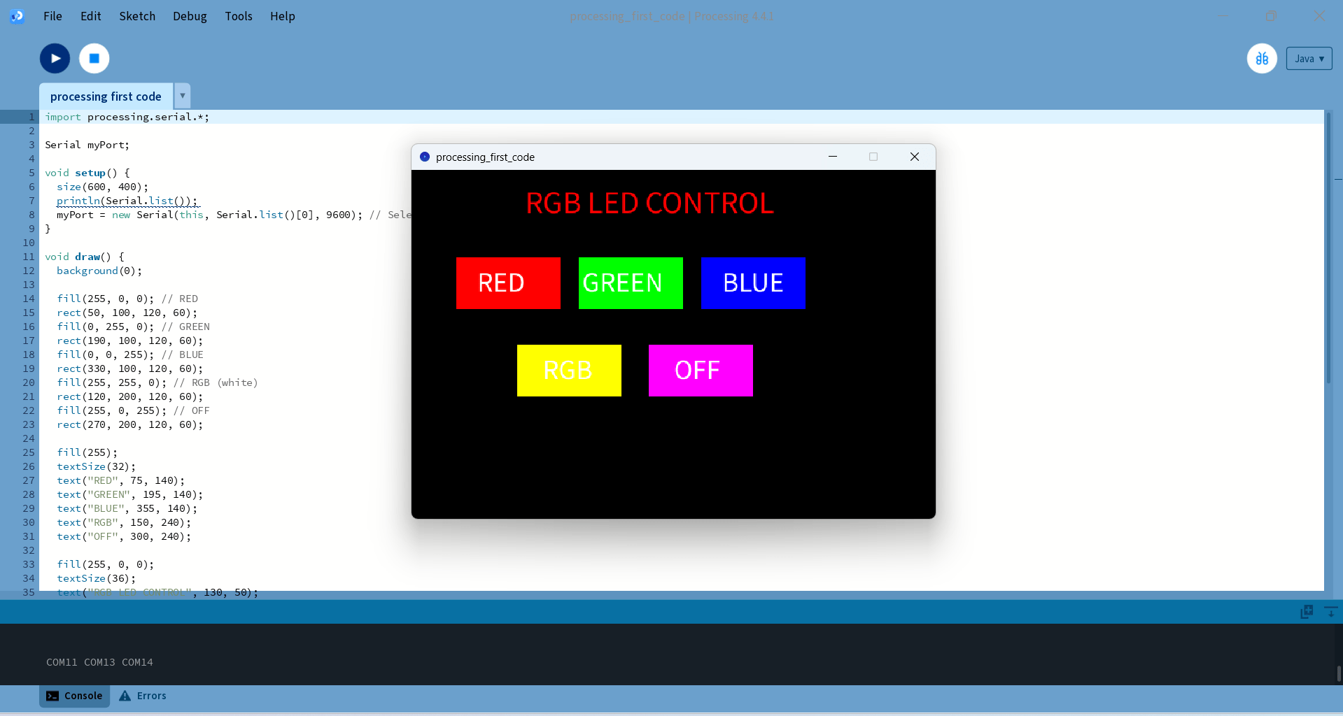
For controlling the RGB LED, I created five buttons. One button controls the red light, the second one controls the green light, and the third controls the blue light. I also created an additional button to turn on all three colors at the same time, and another button to turn them off.
2b. Arduino Coding for Turning On and Off LEDs:
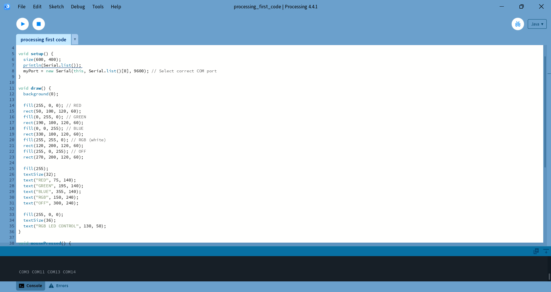
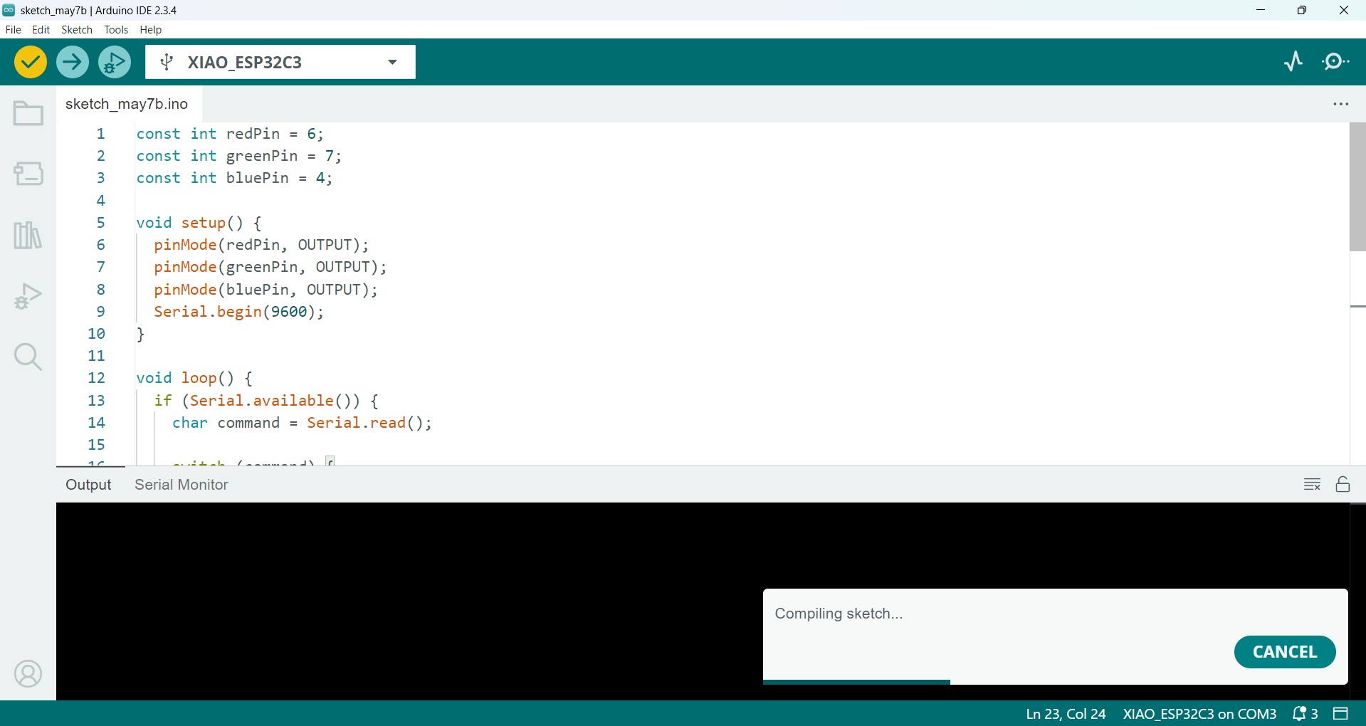
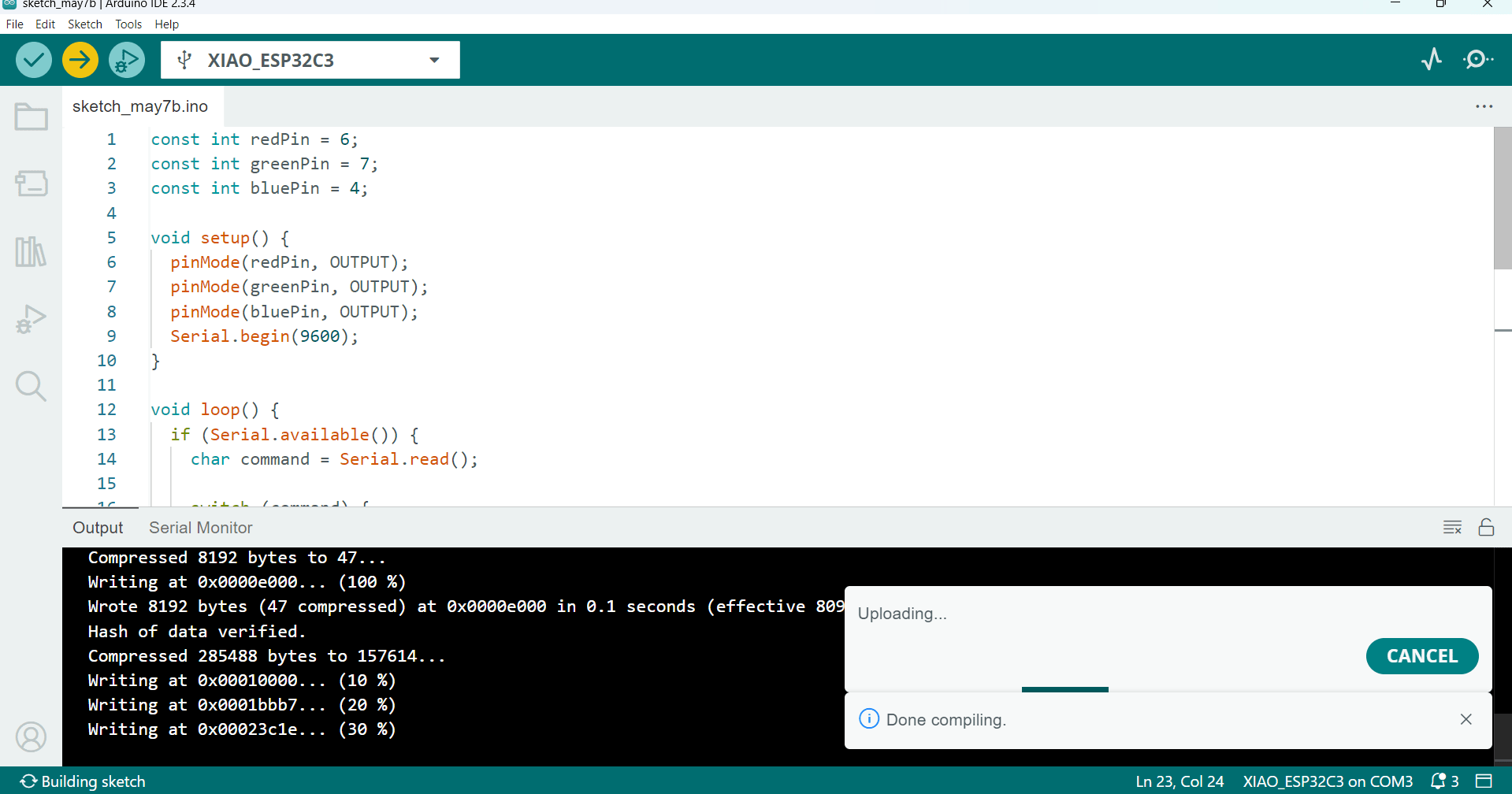
After successfully creating the buttons using Processing, I started writing the code to turn the RGB LED on and off using serial communication. I have shown the implementation in the image below.
Below, I am showing how I connected the RGB LED to the Xiao C3 board.
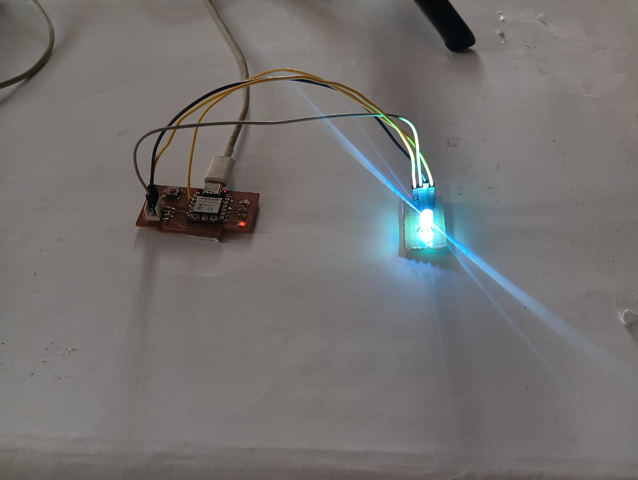
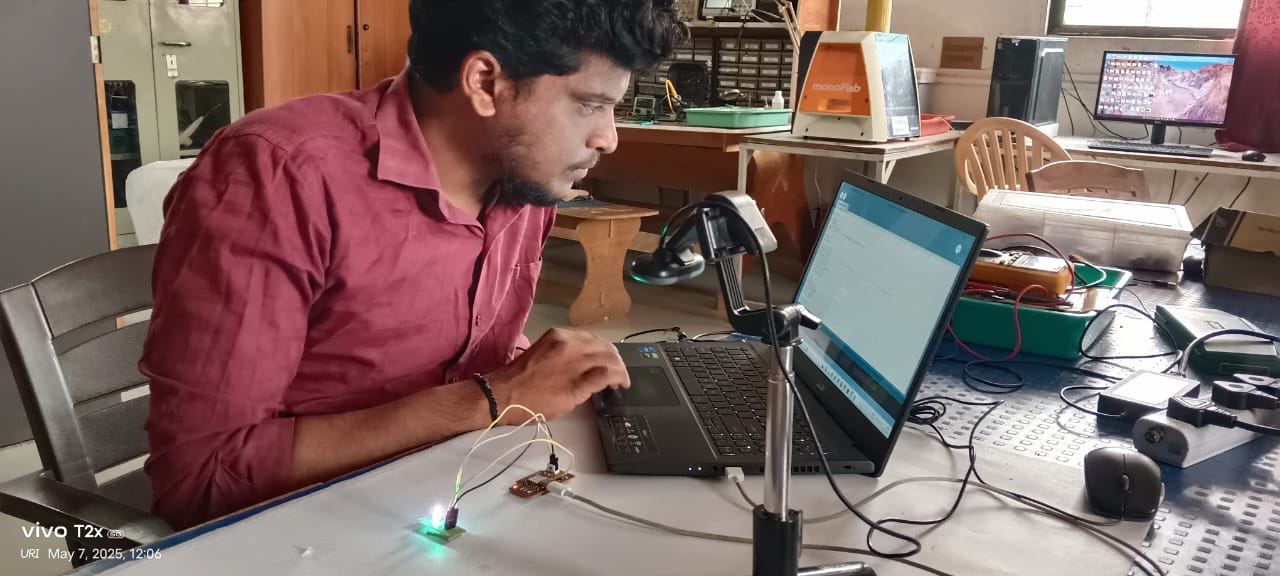
Below, I am showing the working video of controlling the RGB LED using Processing.
Processing: Controlling the RGB LED
import processing.serial.*;

Serial myPort;

void setup() {
    size(600, 400);
    println(Serial.list());
    myPort = new Serial(this, Serial.list()[0], 9600); // Select correct COM port
}

void draw() {
    background(0);

    fill(255, 0, 0); // RED
    rect(50, 100, 120, 60);
    fill(0, 255, 0); // GREEN
    rect(190, 100, 120, 60);
    fill(0, 0, 255); // BLUE
    rect(330, 100, 120, 60);
    fill(255, 255, 0); // RGB (white)
    rect(120, 200, 120, 60);
    fill(255, 0, 255); // OFF
    rect(270, 200, 120, 60);

    fill(255);
    textSize(32);
    text("RED", 75, 140);
    text("GREEN", 195, 140);
    text("BLUE", 355, 140);
    text("RGB", 150, 240);
    text("OFF", 300, 240);

    fill(255, 0, 0);
    textSize(36);
    text("RGB LED CONTROL", 130, 50);
}

void mousePressed() {
    // RED
    if (mouseX > 50 && mouseX < 170 && mouseY > 100 && mouseY < 160) {
    myPort.write('R');
    }
    // GREEN
    else if (mouseX > 190 && mouseX < 310 && mouseY > 100 && mouseY < 160) {
    myPort.write('G');
    }
    // BLUE
    else if (mouseX > 330 && mouseX < 450 && mouseY > 100 && mouseY < 160) {
    myPort.write('B');
    }
    // RGB (White)
    else if (mouseX > 120 && mouseX < 240 && mouseY > 200 && mouseY < 260) {
    myPort.write('A');
    }
    // OFF
    else if (mouseX > 270 && mouseX < 390 && mouseY > 200 && mouseY < 260) {
    myPort.write('O');
    }
}
Arduino Code: Controlling the RGB LED
const int redPin = 6;
const int greenPin = 7;
const int bluePin = 4;

void setup() {
pinMode(redPin, OUTPUT);
pinMode(greenPin, OUTPUT);
pinMode(bluePin, OUTPUT);
Serial.begin(9600);
}

void loop() {
if (Serial.available()) {
char command = Serial.read();

switch (command) {
    case 'R': // Red
    setColor(0, 255, 255);
    break;
    case 'G': // Green
    setColor(255, 0, 255);
    break;
    case 'B': // Blue
    setColor(255, 255, 0);
    break;
    case 'A': // All (RGB)
    setColor(0, 0, 0);
    break;
    case 'O': // OFF
    setColor(255, 255, 255);
    break;
}
}
}

void setColor(int red, int green, int blue) {
analogWrite(redPin, red);
analogWrite(greenPin, green);
analogWrite(bluePin, blue);
}
Positive Outcomes:
This week’s assignment helped me learn many new things. Although I already knew how to build apps using MIT App Inventor, I explored Processing software for the first time and found that it can also be used to control microcontrollers. This was also my first experience working with Java. Even though I didn’t know the language before, I enjoyed learning it and had a good experience using it. Previously, I had only controlled hardware using Python, but this was the first time I used Java for such tasks, and I found it very interesting and enjoyable.
Challenges Encountered:
In this week’s assignment, I faced an issue where the ESP32-C3 Xiao Bluetooth was not connecting to the MIT App Inventor’s Bluetooth client. It kept showing the error: "E (59334) BT_SMP: smp_calculate_link_key_from_long_term_key failed." I spent an entire day troubleshooting the problem but couldn’t find a solution. Due to this, I decided to shift to using the ATtiny microcontroller instead. Apart from this issue, I didn’t face any major challenges during the assignment. Overall, the experience was smooth once I made the switch.