Assignment 15: System Integration
This assignment focuses on documenting the integration of all hardware and software components of the final project into a unified working system. It highlights how different modules—electronics, mechanics, and code—are connected and function together. The goal is to ensure seamless communication and performance among all subsystems. It also includes testing, debugging, and validating the complete functionality of the project.
Highlight Moments of the Week
Objective of the Assignment :
- Design and document the system integration for your final project
1. Overview of the Final Project System :
- Brief description of my final project :
The WiRain Cover project is a smart, automated sliding rain protection system designed specifically for high-elevation windows—such as the one at the Fab Lab in Vigyan Ashram, where rainwater enters through the edges even when the window is closed.
This system serves as an external sliding cover, made from a durable plastic sheet mounted on a rail-based sliding mechanism. The primary goal is to prevent rainwater intrusion, ensuring the safety of equipment, materials, and the comfort of people inside the lab.
The WiRain Cover has dual control modes:
Manual control through a set of push buttons, enabling local operation even without internet.
Remote control via Wi-Fi, allowing the user to open or close the sliding cover through a web interface or mobile application.
The cover can be deployed when it starts raining, and retracted after the rain stops, helping maintain airflow and visibility during normal conditions. The system can also be enhanced with future upgrades, such as automatic rain detection or integration into a smart building management system.
This project not only solves a real-world problem but also demonstrates the use of mechanical design, embedded systems, wireless communication, and user interface development in a compact, practical application.
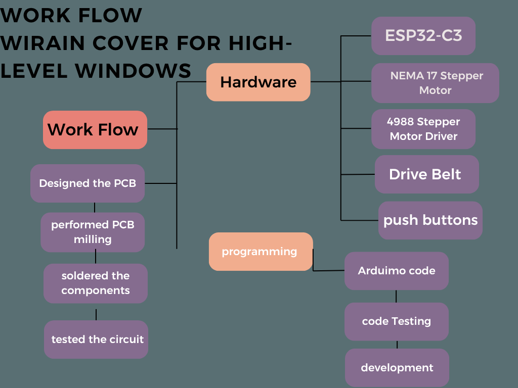
- Integrated System Architecture: Block Diagram of Core Components :
Below, I am presenting the block diagram of my final project, which illustrates how the system works. I have also included a list of some of the components and materials that are ready for assembly in the final build.
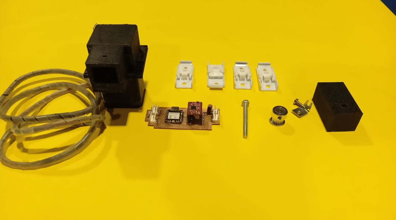
- Components and Materials Used:
Below, I am presenting the materials used in my final project. Along with this, I have included the detailed bill of materials. This provides a complete overview of all components required.
| Item | Qty | Cost (INR) |
|---|---|---|
| ESP32-C3 | 1 | ₹300 |
| Stepper Motor | 1 | ₹250 |
| Motor Driver A4988 | 1 | ₹150 |
| Plastic transparent Cover | 1 | ₹200 |
| Push Buttons | 2 | ₹40 |
| Limit Switches | 2 | ₹60 |
| Aluminum rails | 1 | ₹500 |
| Power Adapter | 1 | ₹150 |
| pcb | 1 | ₹100 |
| 10M GT2 Width 6mm White Open Timing Belt | 1 | ₹300 | Misc (wires, nuts, etc.) | nun | ₹100 |
2. Electronics Integration
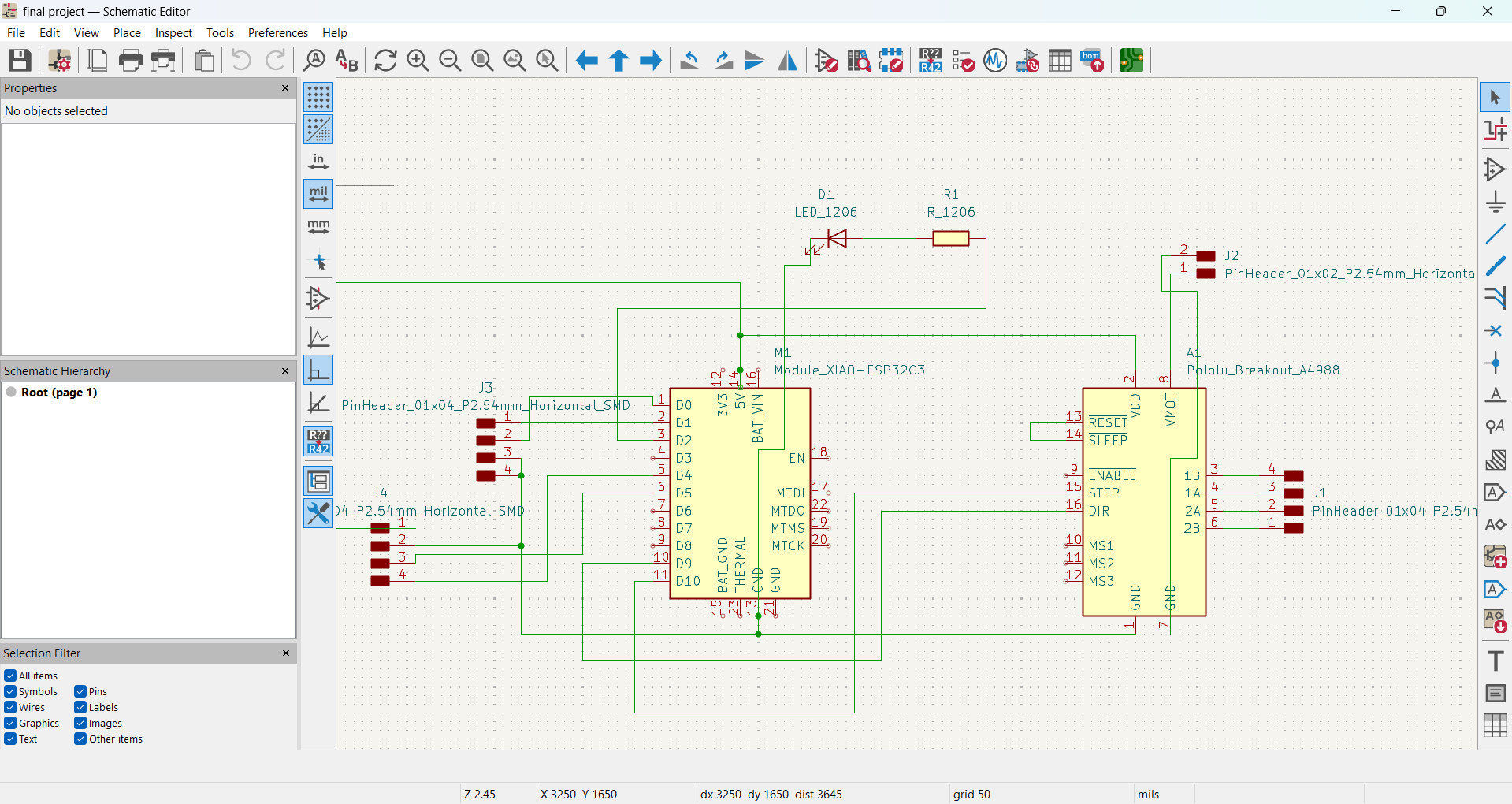
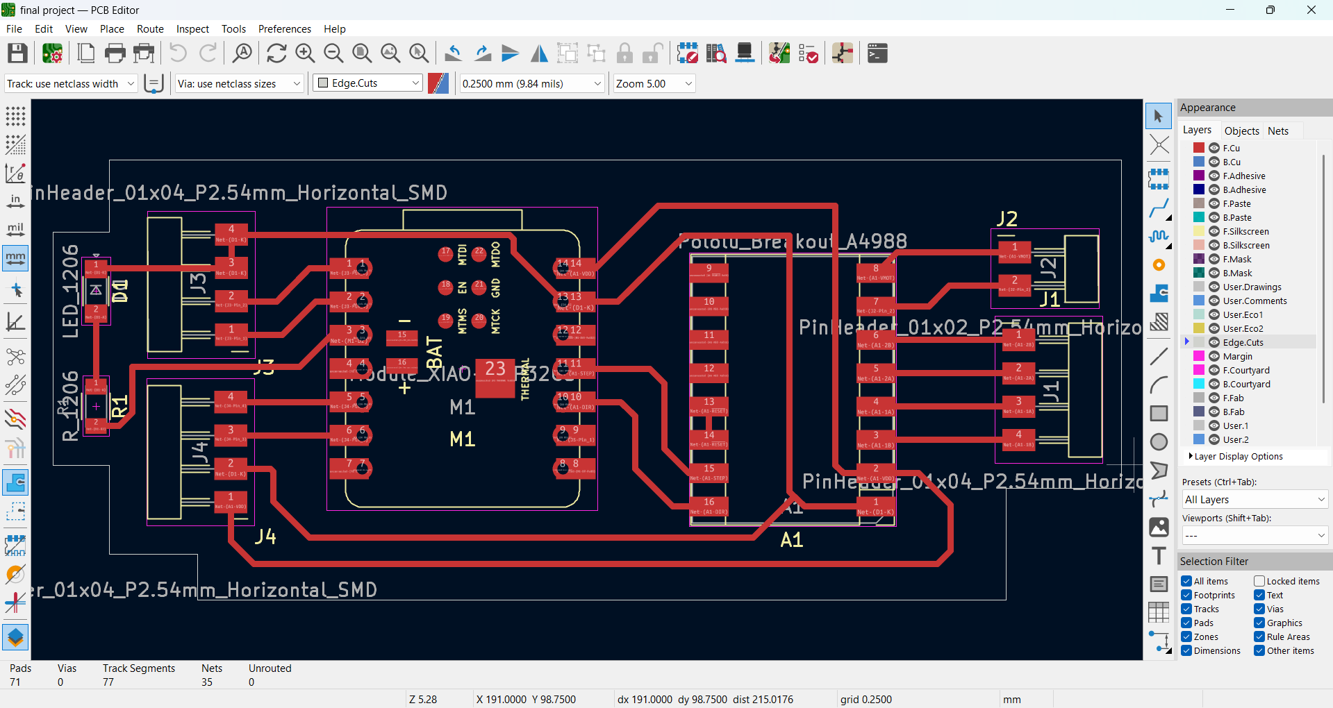
- Designing the PCB :
Below, I am showing how I created the schematic diagram and designed the PCB for my final-project.
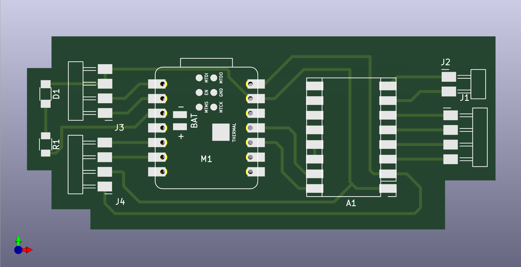
PCB design in 3D view :
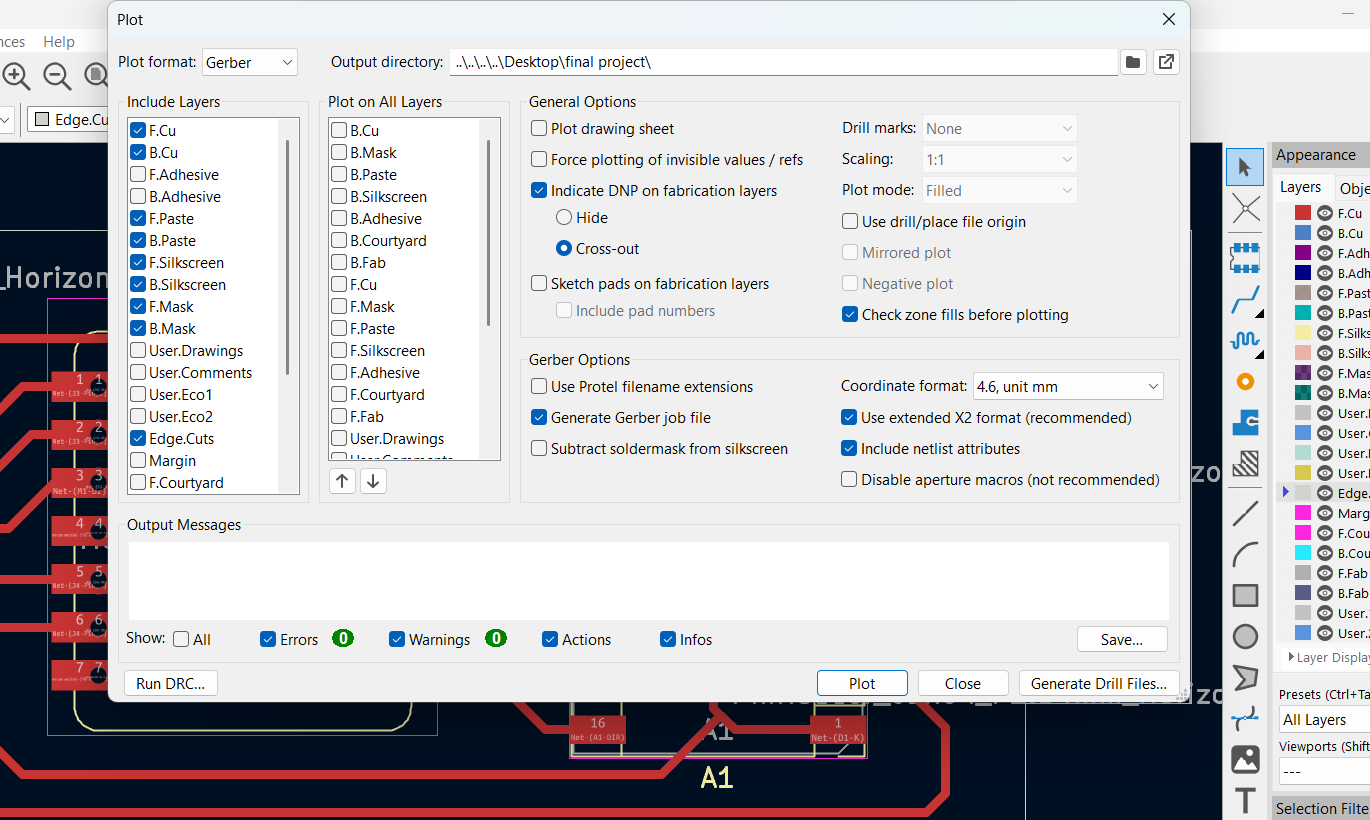
- PCB Milling Process :
After completing the PCB design using KiCad, I exported the file into my pc. Below, I am showing an image .
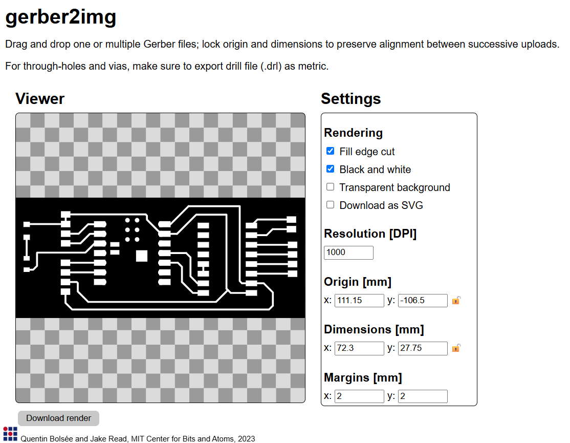
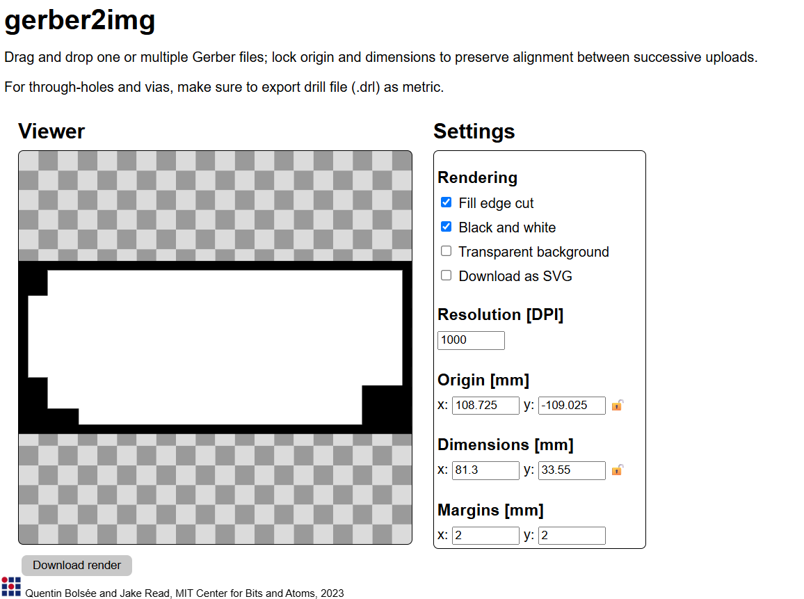
I converted the Gerber files to PNG format using the gerber2image tool. This helped visualize the PCB layers before the milling process.
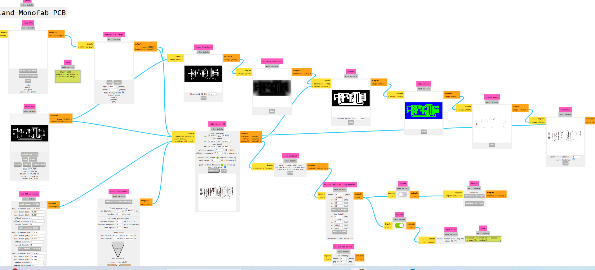
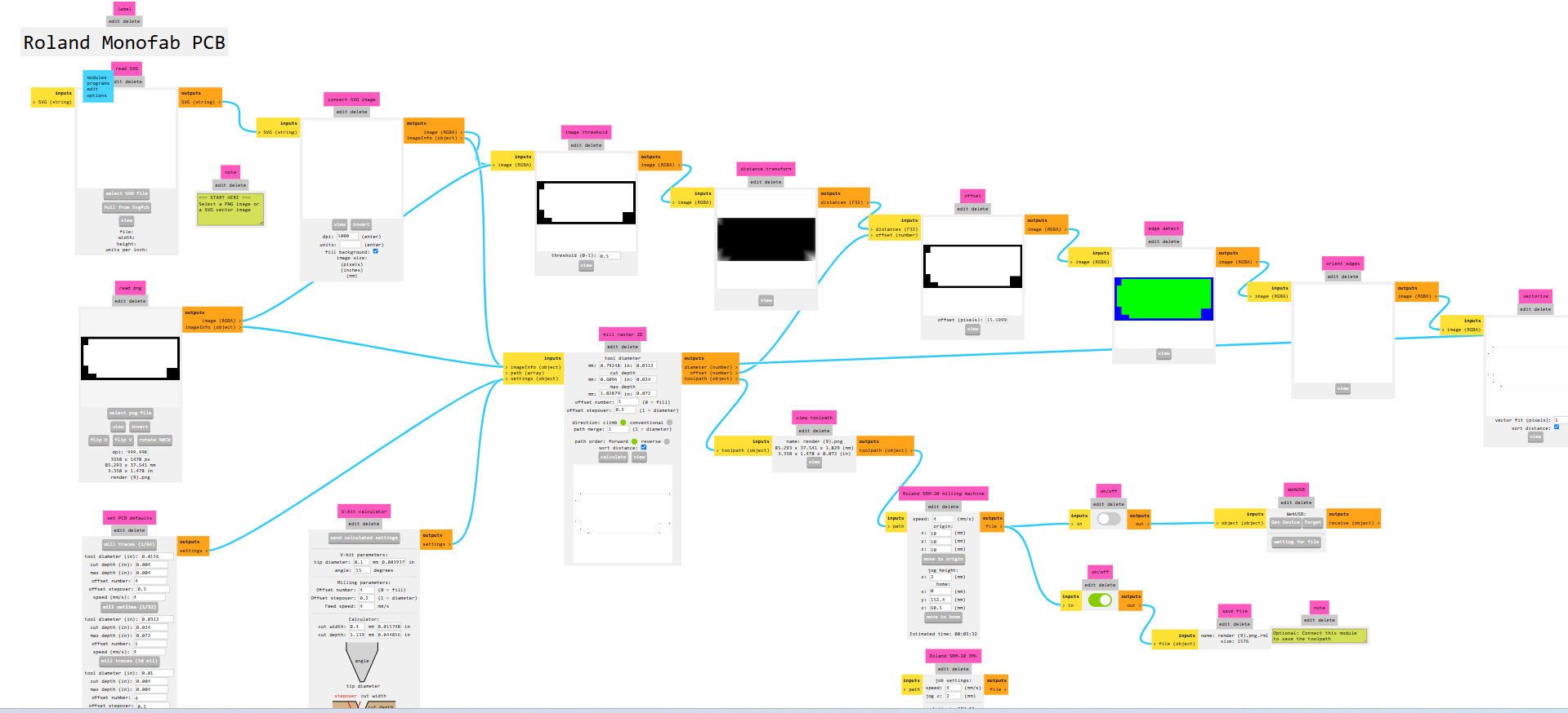
Creating Milling Toolpaths Using Mods C :
I generated the toolpath for PCB milling using Mods C configured for the SRM-20 machine. This step ensures accurate milling paths tailored for the Roland SRM-20.
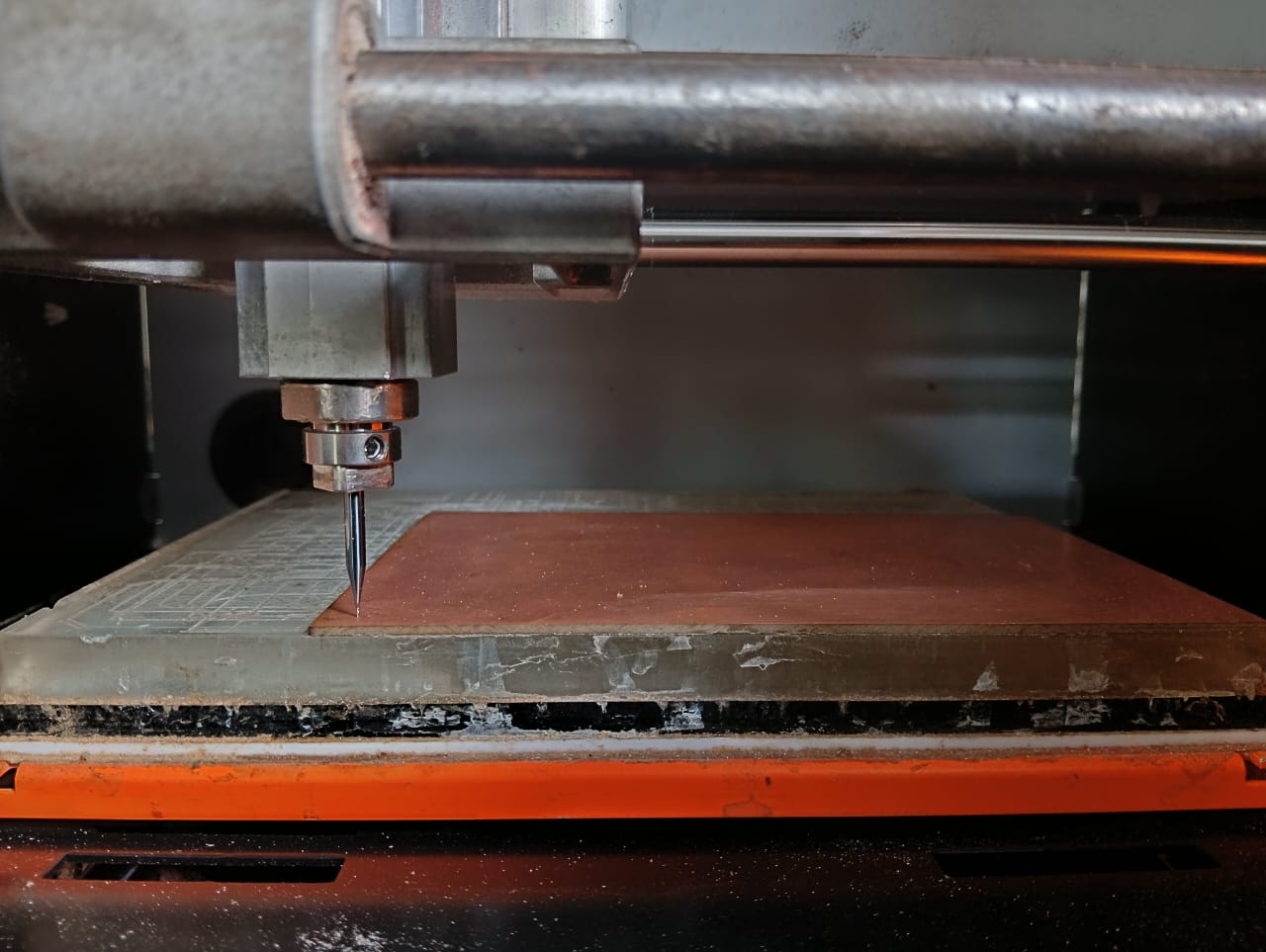
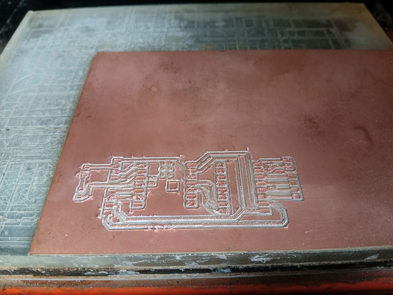
After completing the toolpath generation, I started the PCB milling process. Before beginning, I set the SRM-20 machine to the origin position and initiated the process with the trace mill. Below, I am showing how the machine milled the PCB trace cut.
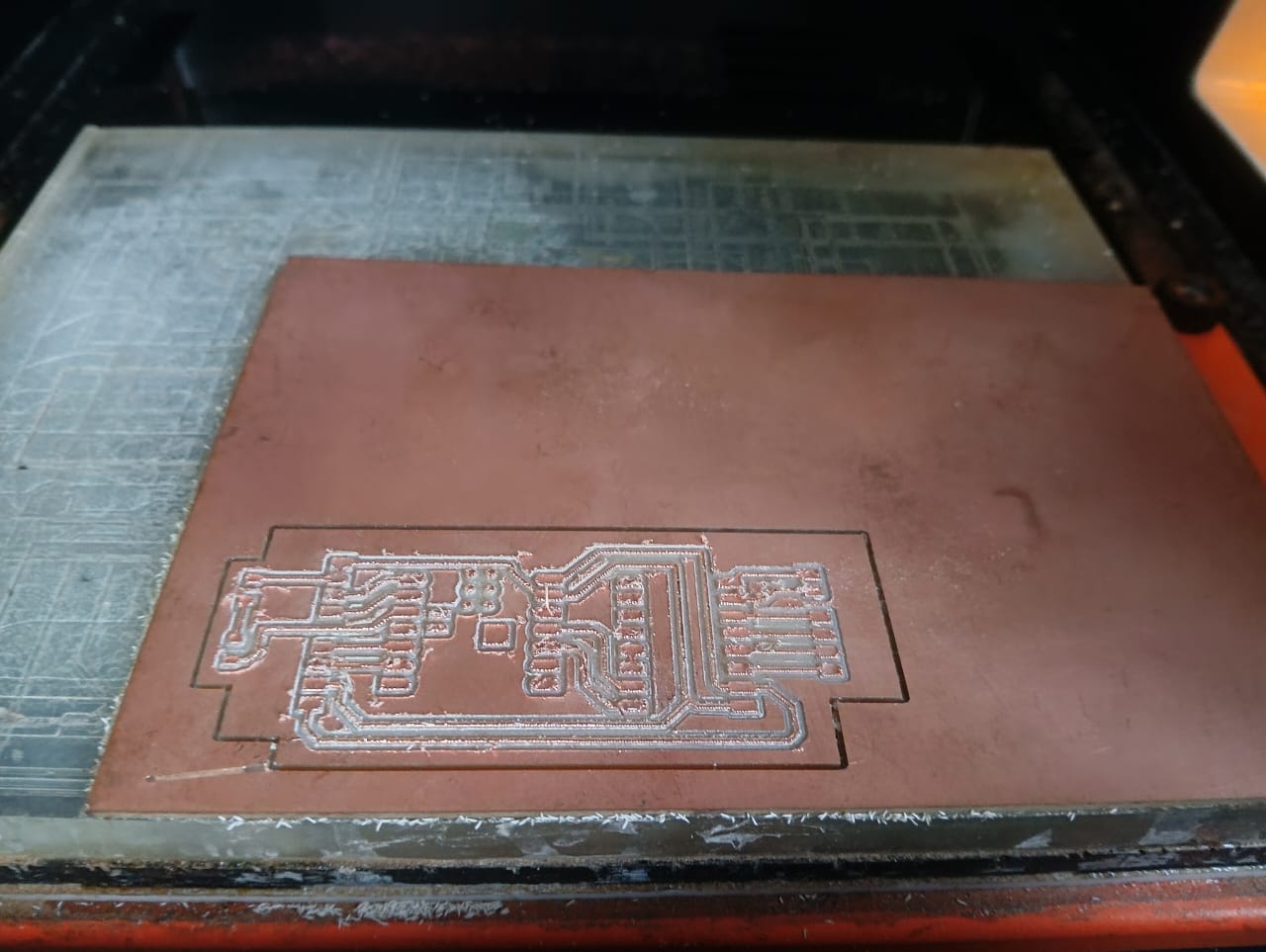
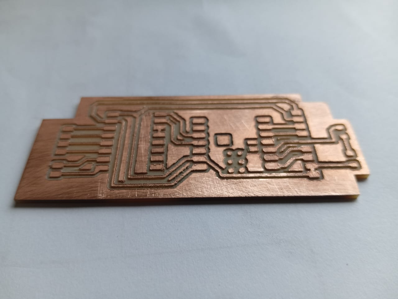
After completing the trace cut, I proceeded with the edge cut to shape the final PCB. Below, I am showing how the edge cut was performed, along with the final result of my milled PCB.
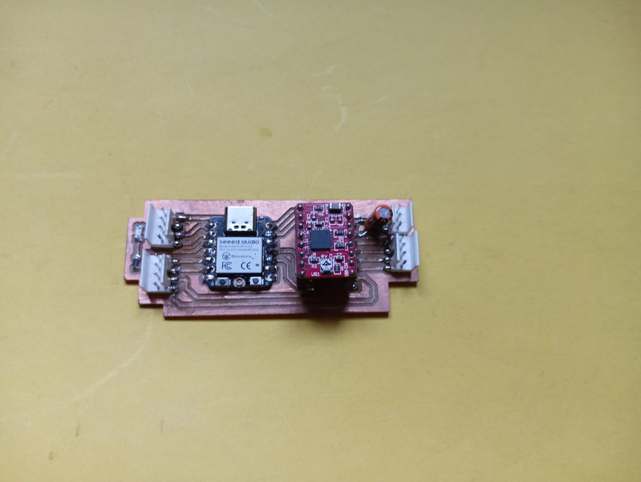
After completing the milling process, I started soldering the components onto my board. I soldered all the components according to my design. Below, I am showing the final assembled product.
3. Mechanical Integration :
Coming to mechanical integration, I purchased some materials directly from the market because producing them using 3D printing or laser cutting would have been more expensive. I modified these purchased parts according to my requirements by adding supports and incorporating a belt mechanism. Below, I am explaining how I completed the mechanical integration.
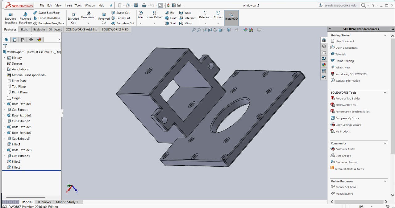
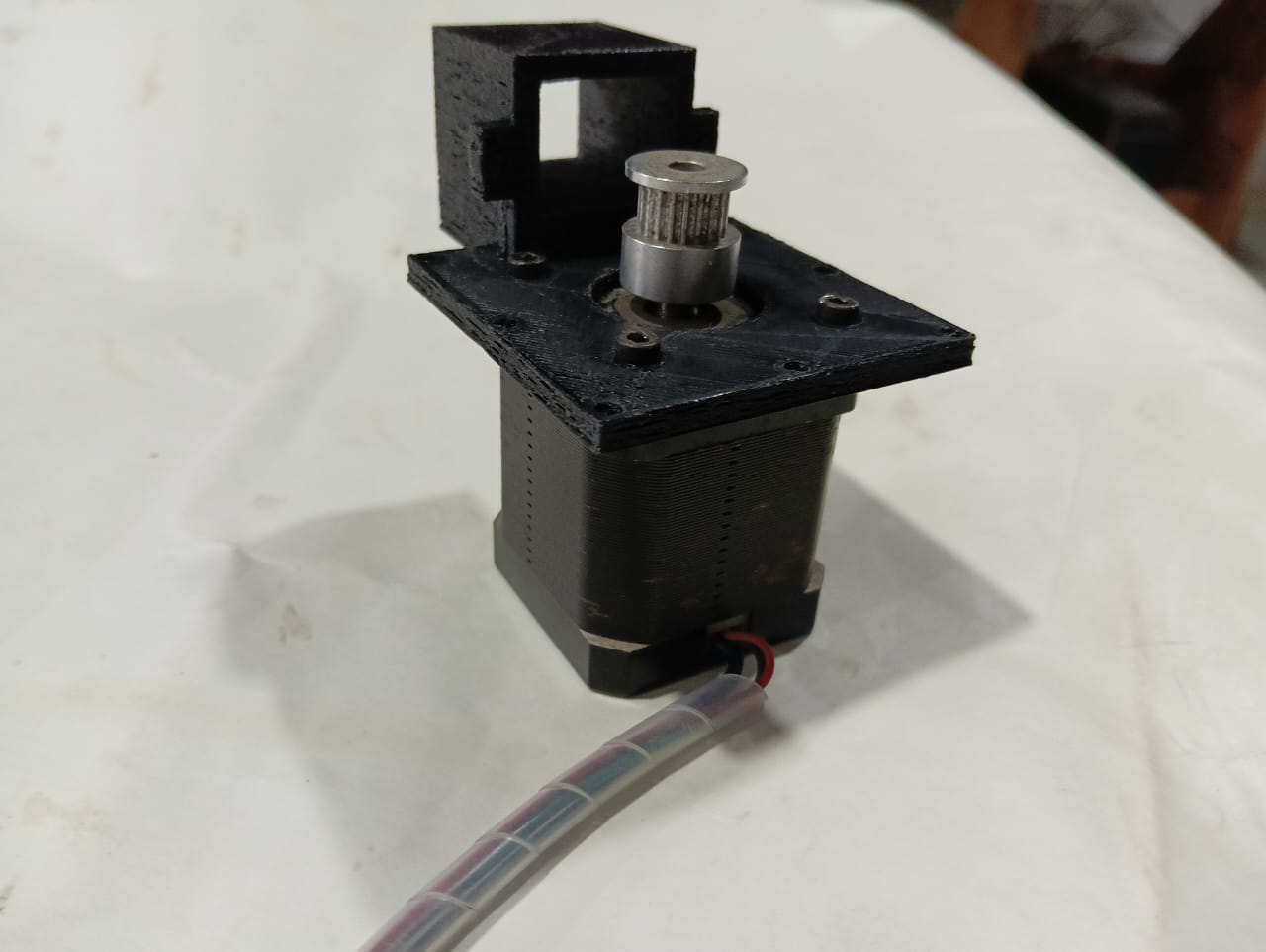
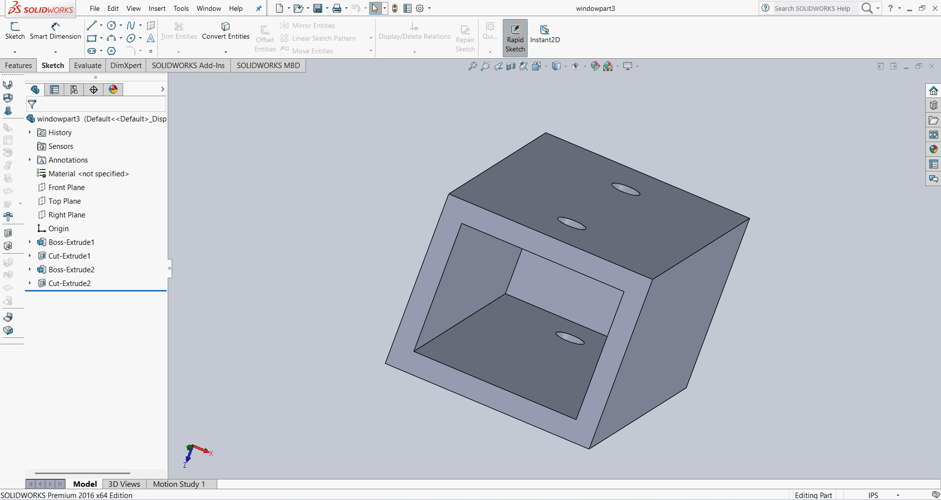
1.I designed a holder to securely hold the motor during operation. Below, I am showing the design and how I fixed the motor to the holder.
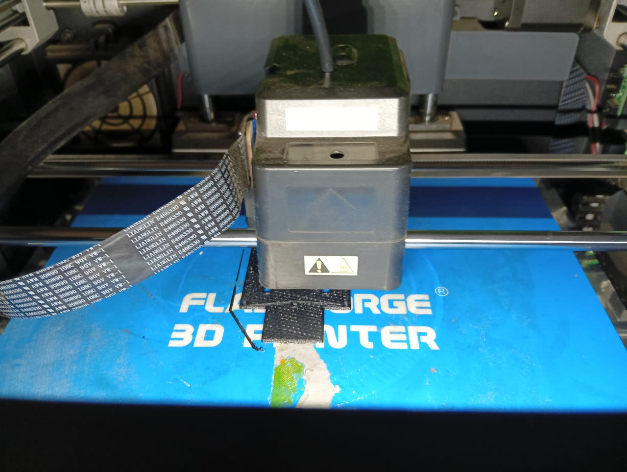
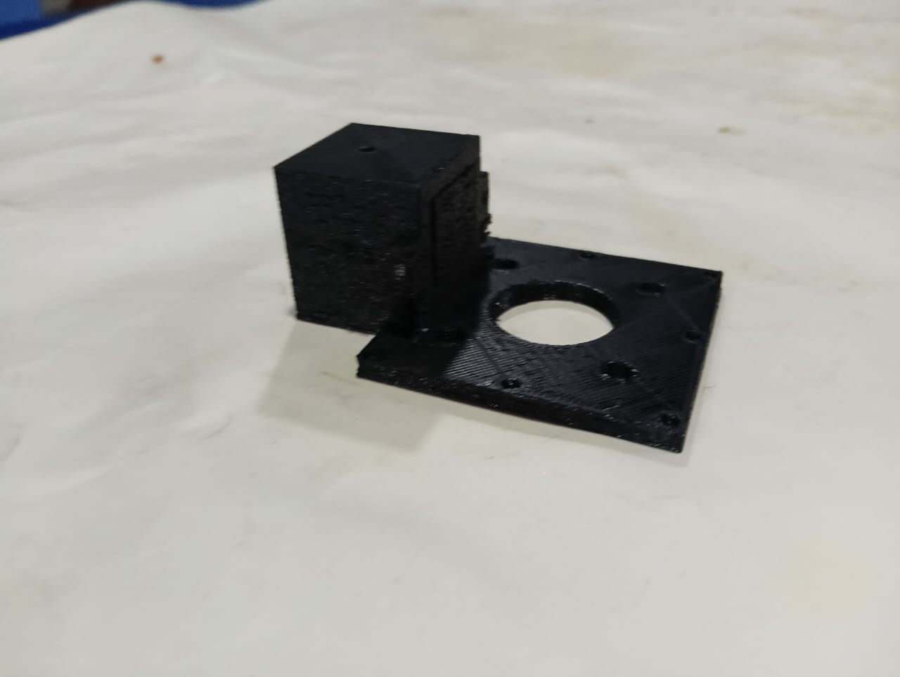
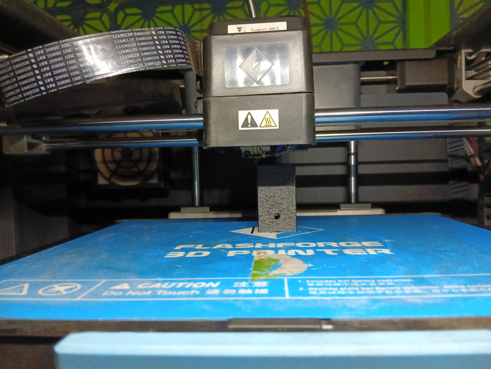
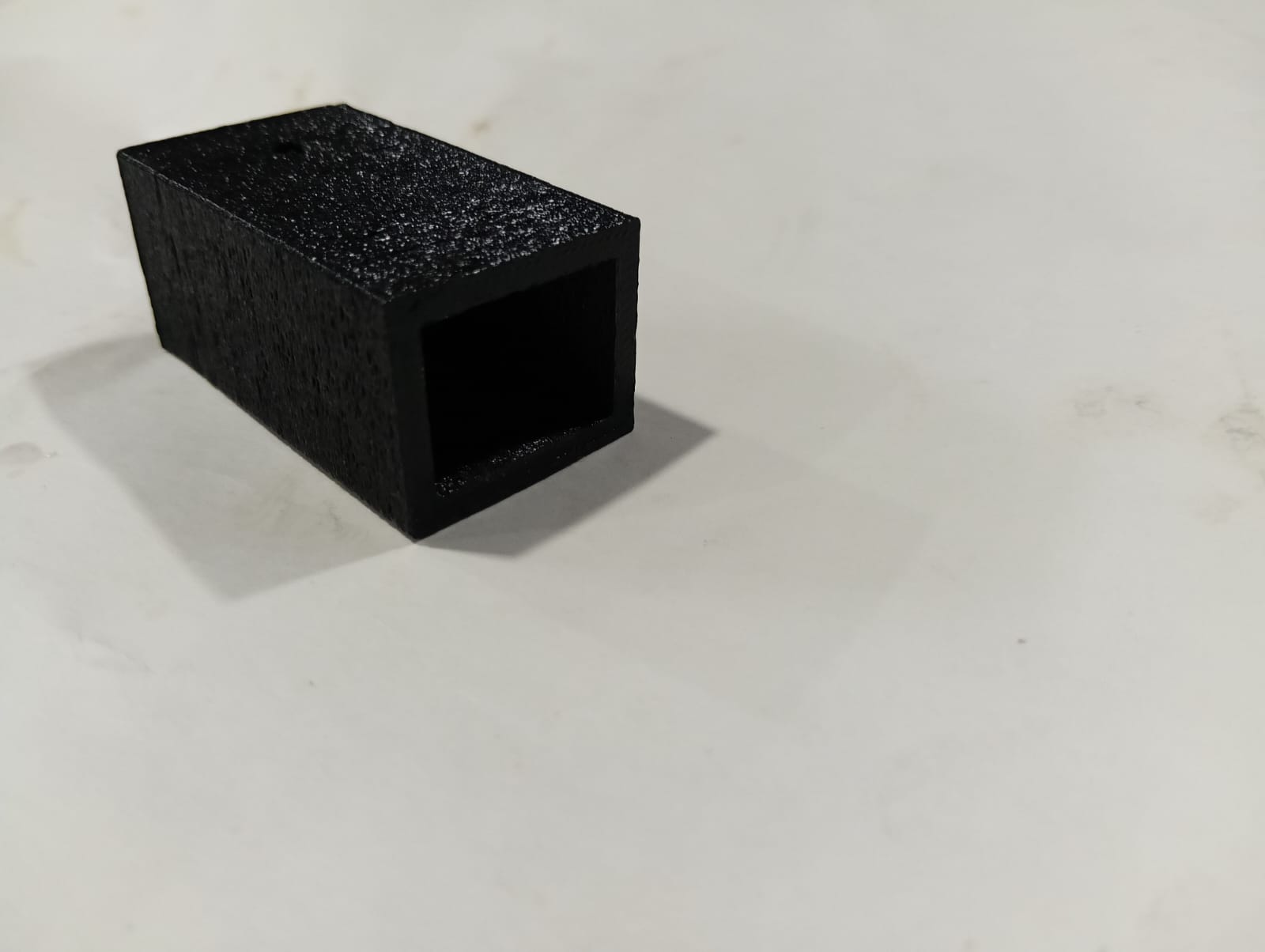
After completing the above design, I printed it using a 3D printer. Below, I am showing the printed part.
In my project, I am using a belt drive mechanism, which requires another pulley at the opposite end. For that, I designed an additional pulley support. Below, I am showing the design of the second pulley support along with the 3D printing process.
Below, I am showing the 3D printed part of the second pulley support.
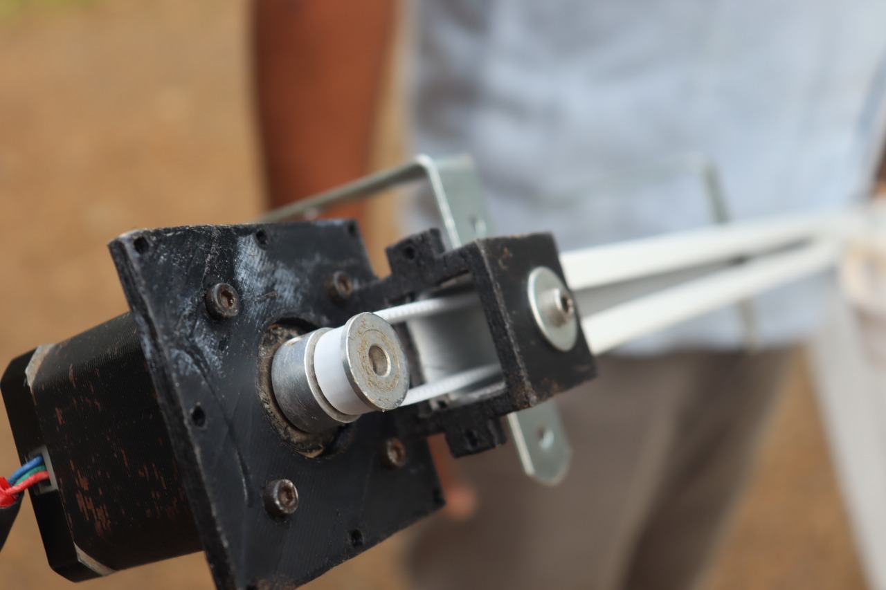
Now my parts are ready for installation. I started assembling the designed components into my project mechanism. Below, I am showing how I installed the mechanism into my project.
First, I placed the belt onto the aluminum rails. After that, I fixed the stepper motor at one end using the custom-designed motor holder.
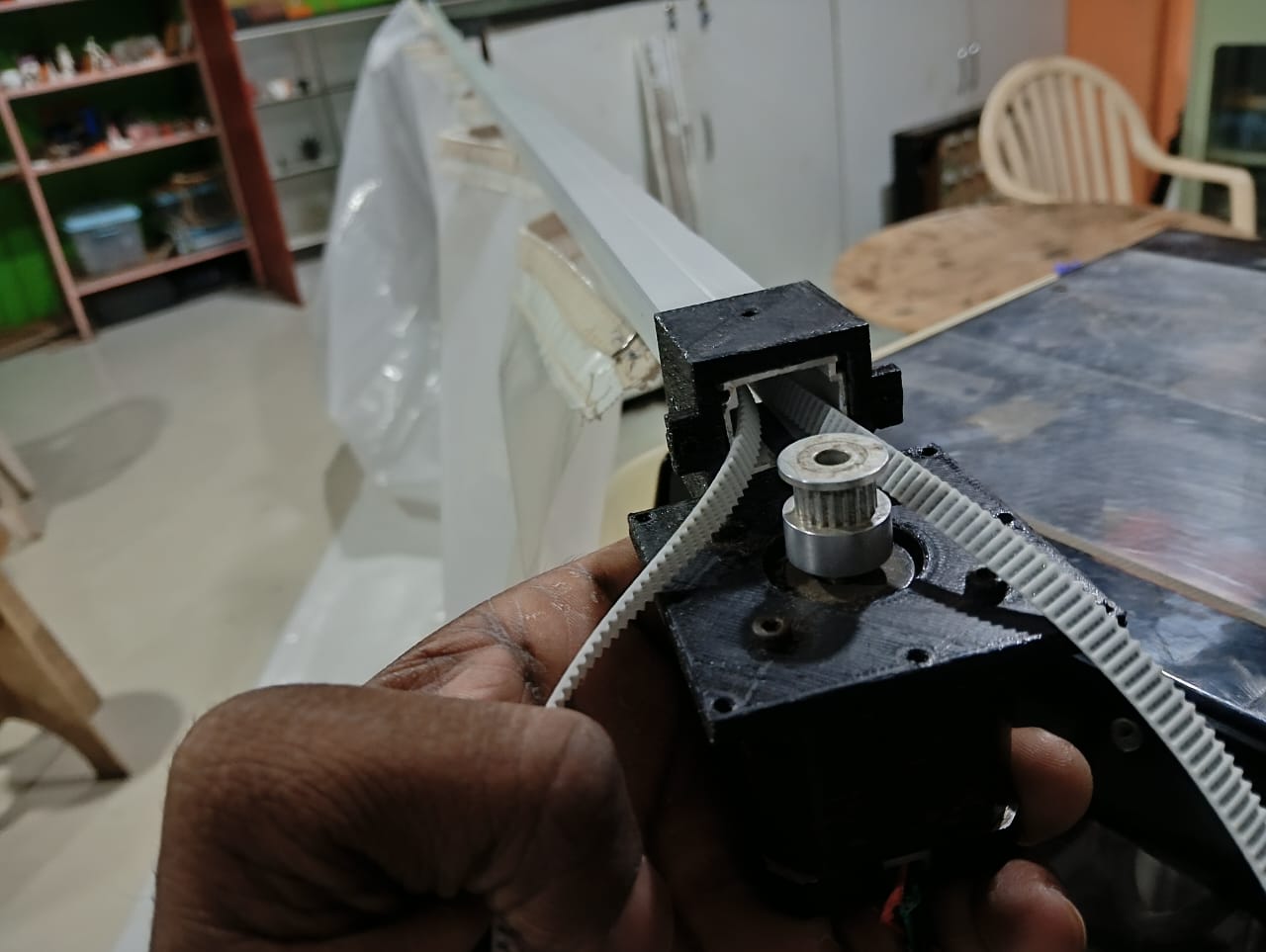
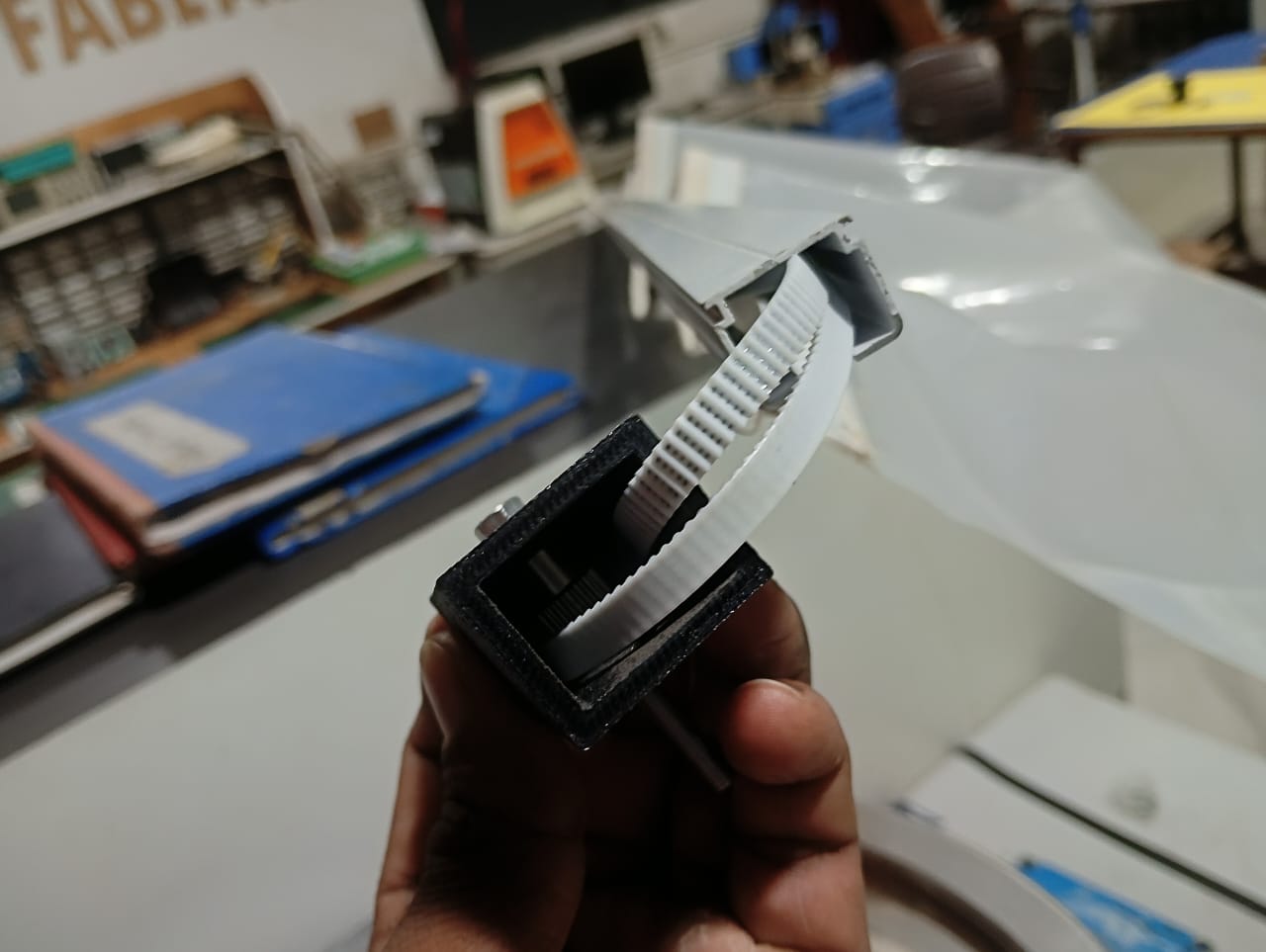
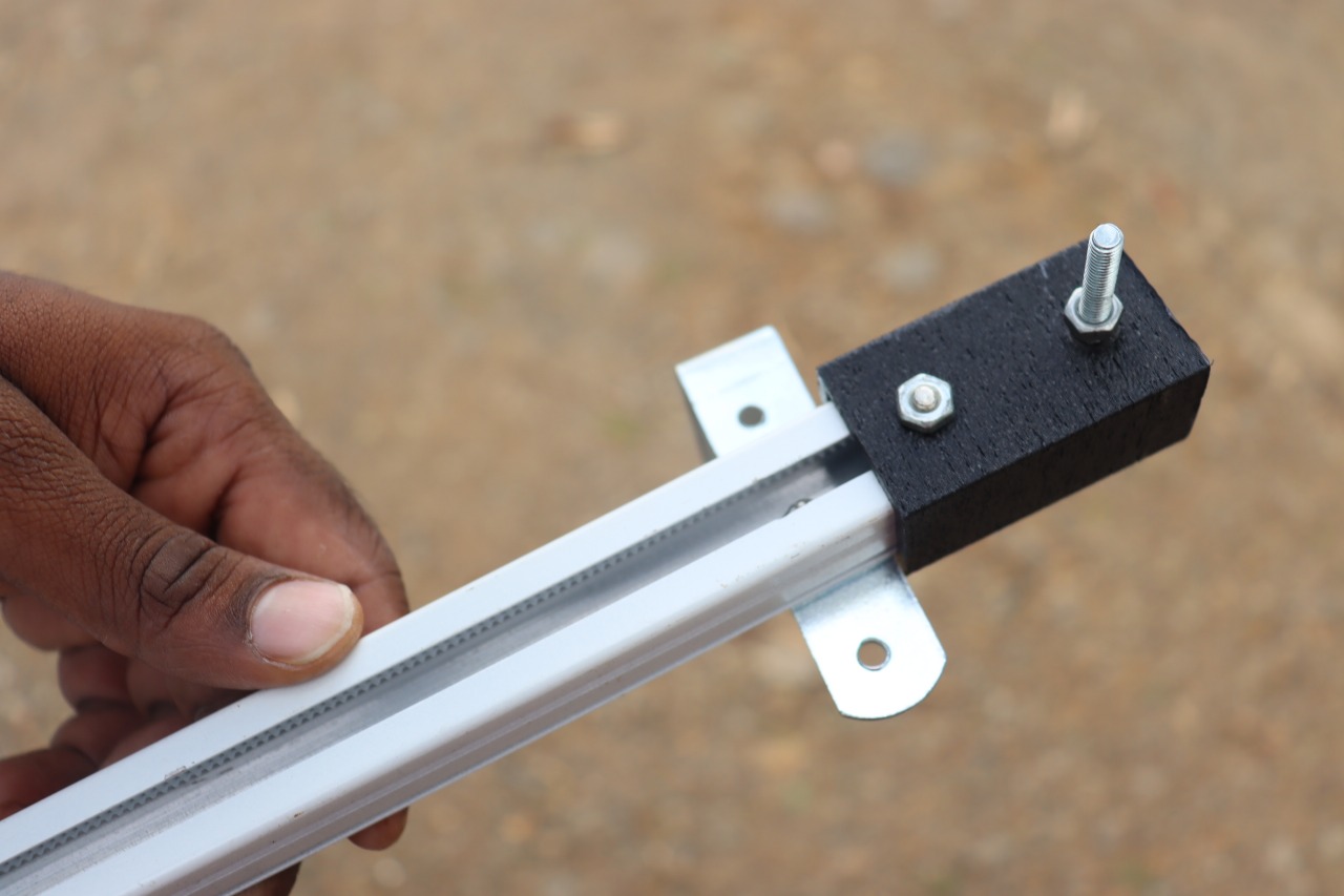
At the second end, a pulley was required, so I added the pulley and fixed it to the aluminum rail. The belt runs over this pulley, allowing it to rotate smoothly as part of the mechanism.
4. Software Integration :
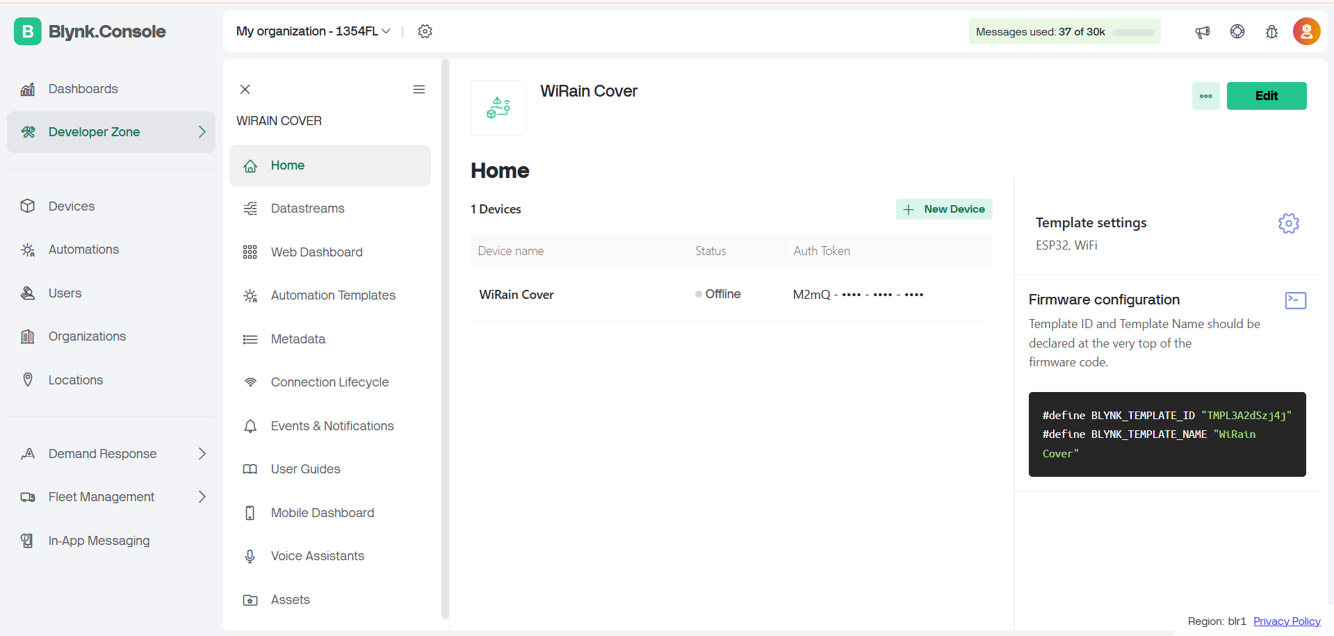
In my project, I am using the ESP32-C3 microcontroller for control and communication. I programmed it using the Arduino IDE. Below, I am providing the programming section of my project.
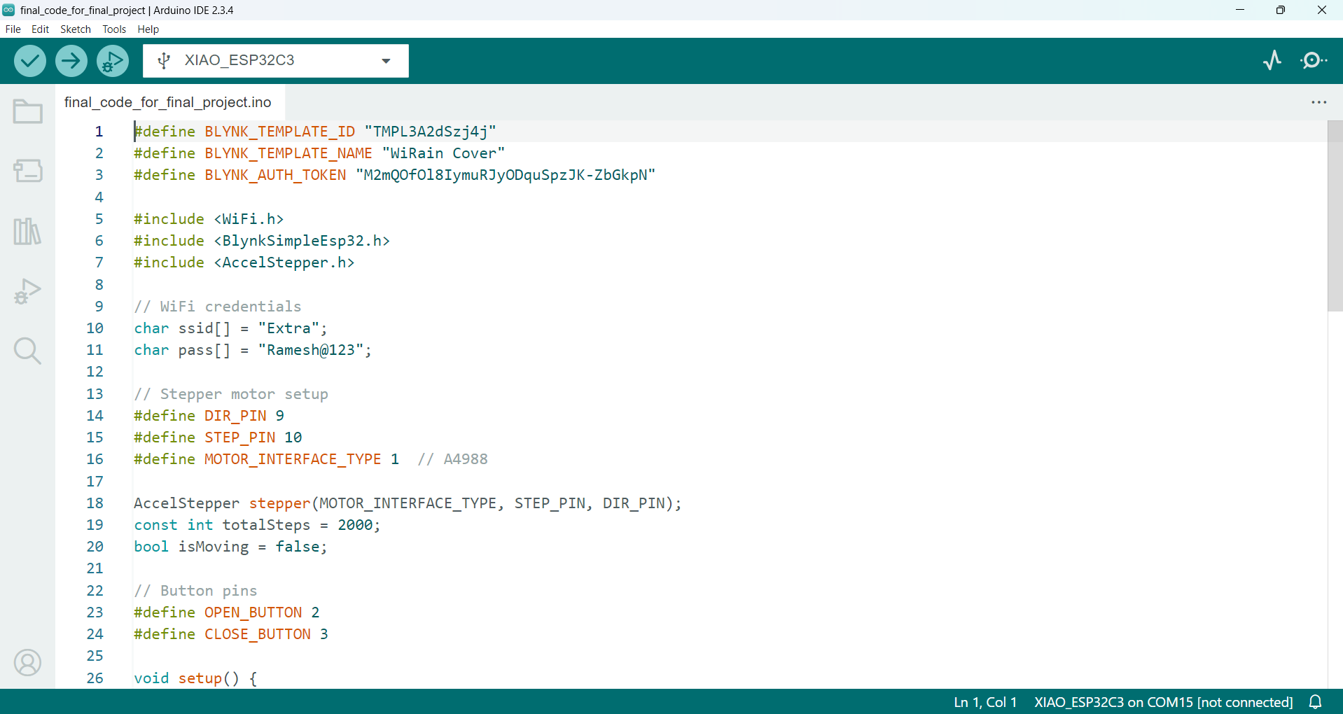
Programming of My Project :
Arduino Code:
#define BLYNK_TEMPLATE_ID "TMPL3A2dSzj4j"
#define BLYNK_TEMPLATE_NAME "WiRain Cover"
#define BLYNK_AUTH_TOKEN "M2mQOfOl8IymuRJyODquSpzJK-ZbGkpN"

#include <WiFi.h>
#include <BlynkSimpleEsp32.h>
#include <AccelStepper.h>

// WiFi credentials
char ssid[] = "Extra";
char pass[] = "Ramesh@123";

// Stepper motor setup
#define DIR_PIN 9
#define STEP_PIN 10
#define MOTOR_INTERFACE_TYPE 1  // A4988

AccelStepper stepper(MOTOR_INTERFACE_TYPE, STEP_PIN, DIR_PIN);
const int totalSteps = 2000;
bool isMoving = false;

// Button pins
#define OPEN_BUTTON 2
#define CLOSE_BUTTON 3

void setup() {
  pinMode(OPEN_BUTTON, INPUT_PULLUP);
  pinMode(CLOSE_BUTTON, INPUT_PULLUP);

  stepper.setMaxSpeed(1000);
  stepper.setAcceleration(500);
  stepper.setCurrentPosition(0);  // Start closed

  Blynk.begin(BLYNK_AUTH_TOKEN, ssid, pass);
}

// Blynk handler: Open command (V0)
BLYNK_WRITE(V0) {
  if (!isMoving && stepper.currentPosition() != totalSteps) {
    stepper.moveTo(totalSteps);
    isMoving = true;
  }
}

// Blynk handler: Close command (V1)
BLYNK_WRITE(V1) {
  if (!isMoving && stepper.currentPosition() != 0) {
    stepper.moveTo(0);
    isMoving = true;
  }
}

void loop() {
  Blynk.run();

  // Move stepper if needed
  if (isMoving) {
    stepper.run();
    if (!stepper.isRunning()) {
      isMoving = false;
    }
  } else {
    // Handle buttons only when motor is idle
    if (digitalRead(OPEN_BUTTON) == LOW && stepper.currentPosition() != totalSteps) {
      stepper.moveTo(totalSteps);
      isMoving = true;
      delay(200);  // Debounce
    }

    if (digitalRead(CLOSE_BUTTON) == LOW && stepper.currentPosition() != 0) {
      stepper.moveTo(0);
      isMoving = true;
      delay(200);  // Debounce
    }
  }
}
Explanation of code:
1. This code connects an ESP32 to Wi-Fi and Blynk to control a stepper motor.
2. The motor opens or closes rain cover using Blynk virtual buttons V0 and V1.
3. Two physical buttons are also used to open and close when the motor is idle.
4. The motor moves to either 0 or 2000 steps based on the command.
5. A flag is Moving ensures the motor doesn't receive overlapping commands while it's running.
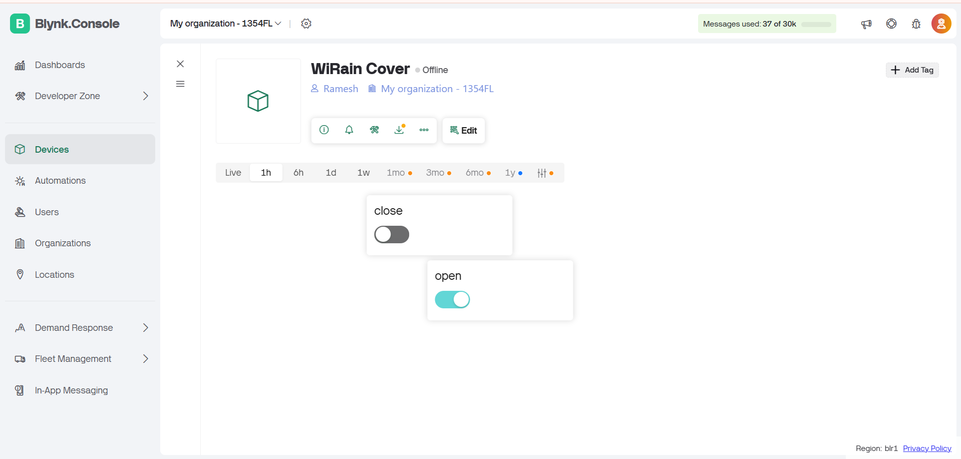
5. Networking & Communication and User Interface Integration :
In my project, I am using two types of communication: one is manual control using push buttons, and the other is cloud-based control using the Blynk platform. My project works in parallel with both communication methods — for example, if I open the WiRain Cover using Blynk, I can also close it manually using the push button.
For Wi-Fi Control :
For Wi-Fi-based control, I am using the Blynk platform, which allows me to operate the project remotely through a mobile application over the internet.
For Manual Control
For manual operation, I am using push buttons connected to the ESP32-C3. These buttons allow me to control the system locally without relying on internet connectivity.
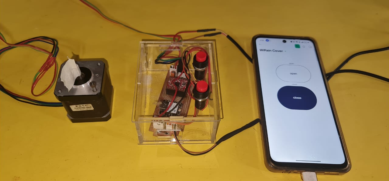
6. Testing and Troubleshooting :
First, I tested the stepper motor using manual control. Then, I tested it using both Wi-Fi (via Blynk) and manual control together. Below, I am showing the results of these tests.
Positive Outcomes:
This week, I made significant progress and almost completed my final project. I gained a clear understanding of how to integrate different systems step by step. The assignment helped me connect hardware, software, and control logic effectively. I now feel more confident in planning and executing the full project workflow. This experience gave me a strong foundation for completing my final project successfully.
Challenges Encountered:
In this assignment, I faced several challenges, starting from identifying the problem statement to planning its solution. One major challenge was designing the mechanism to slide the cover properly for my project. Fixing the mechanical part took time, as I had to ensure smooth and stable movement without using any limit switches. Instead of using limit switches, I relied on step count and careful calibration to control the motor's range. By following a step-by-step approach, I was able to overcome these difficulties and move closer to completing my final project.