This assignment is about documenting what I learned in Electronics Design that includes basics of electronics, components, circuits, test equipment, electronic design software for PCB design and simulation. I have documented how I used Eagle software in designing PCB for my own Hello world board along with how I used test equipment to observe the operation of a microcontroller circuit board while working on my individual and group assignment. I was able to design, make and program my own 'Hello World!' board. I have always been in scared of electronics. Now, I am loving electronics. I am also documenting what went well, what went wrong, how I would do things differently in next assignment and my learning outcomes.
The field of electronics is a branch of physics and electrical engineering that deals with the emission, behaviour and effects of electrons using electronic devices. Electronics uses active devices to control electron flow by amplification and rectification, which distinguishes it from classical electrical engineering, which only uses passive effects such as resistance, capacitance and inductance to control electric current flow.
Electronics has hugely influenced the development of modern society. The identification of the electron in 1897, along with the subsequent invention of the vacuum tube which could amplify and rectify small electrical signals, inaugurated the field of electronics and the electron age. Practical applications started with the invention of the diode by Ambrose Fleming and the triode by Lee De Forest in the early 1900s, which made the detection of small electrical voltages such as radio signals from an radio antenna possible with a non-mechanical device. The growth of electronics was rapid. And by the early 1920s, commercial radio broadcasting and communications were becoming widespread and electronic amplifiers were being used in such diverse applications as long distance telephony and the music recording industry. Click here to read more.
Before we learn more about electronic devices, components, test equipment, etc., it is important to learn about some of the basic terminologies, concepts and laws in electronics like the ones mentione below.
Current
Current is a flow of electrical charge carriers, usually electrons or electron-deficient atoms. The common symbol for current is the uppercase letter I. The standard unit is the ampere, symbolized by A. One ampere of current represents one coulomb of electrical charge (6.24 x 10¹⁸ charge carriers) moving past a specific point in one second. Physicists consider current to flow from relatively positive points to relatively negative points; this is called conventional current or Franklin current. Electrons, the most common charge carriers, are negatively charged. They flow from relatively negative points to relatively positive points.
There are two types of electrical signals, those being alternating current (AC), and direct current (DC).
With alternating current, the direction electricity flows throughout the circuit is constantly reversing. You may even say that it is alternating direction. The rate of reversal is measured in Hertz, which is the number of reversals per second. So, when they say that the India power supply is 50 Hz, what they mean is that it is reversing 100 times per second (twice per cycle).
With Direct Current, electricity flows in one direction between power and ground. In this arrangement there is always a positive source of voltage and ground (0V) source of voltage. You can test this by reading a battery with a multimeter.
An example of pure DC is the current produced by an electrochemical cell. The output of a power-supply rectifier, prior to filtering, is an example of pulsating DC. The output of common utility outlets is AC.
Voltage
Voltage, also called electromotive force, is a quantitative expression of the potential difference in charge between two points in an electrical field. The greater the voltage, the greater the flow of electrical current (that is, the quantity of charge carriers that pass a fixed point per unit of time) through a conducting or semiconducting medium for a given resistance to the flow. Voltage is symbolized by an uppercase italic letter V or E. The standard unit is the volt, symbolized by a non-italic uppercase letter V. One volt will drive one coulomb (6.24 x 10^18) charge carriers, such as electrons, through a resistance of one ohm in one second.
Voltage can be direct or alternating. A direct voltage maintains the same polarity at all times. In an alternating voltage, the polarity reverses direction periodically. The number of complete cycles per second is the frequency, which is measured in hertz (one cycle per second), kilohertz, megahertz, gigahertz, or terahertz. An example of direct voltage is the potential difference between the terminals of an electrochemical cell. Alternating voltage exists between the terminals of a common utility outlet.
A voltage produces an electrostatic field, even if no charge carriers move (that is, no current flows). As the voltage increases between two points separated by a specific distance, the electrostatic field becomes more intense. As the separation increases between two points having a given voltage with respect to each other, the electrostatic flux density diminishes in the region between them.
Resistance
Resistance is the opposition that a substance offers to the flow of electric current. It is represented by the uppercase letter R. The standard unit of resistance is the ohm, sometimes written out as a word, and sometimes symbolized by the uppercase Greek letter omega.
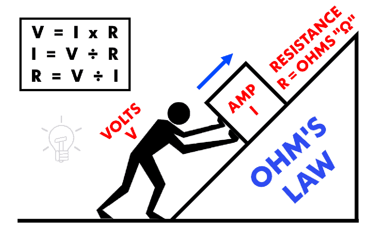
When an electric current of one ampere passes through a component across which a potential difference (voltage) of one volt exists, then the resistance of that component is one ohm. (For more discussion of the relationship among current, resistance and voltage, see Ohm's law below.)
In general, when the applied voltage is held constant, the current in a direct-current (DC) electrical circuit is inversely proportional to the resistance. If the resistance is doubled, the current is cut in half; if the resistance is halved, the current is doubled. This rule also holds true for most low-frequency alternating-current (AC) systems, such as household utility circuits. In some AC circuits, especially at high frequencies, the situation is more complex because some components in these systems can store and release energy, as well as dissipating or converting it.
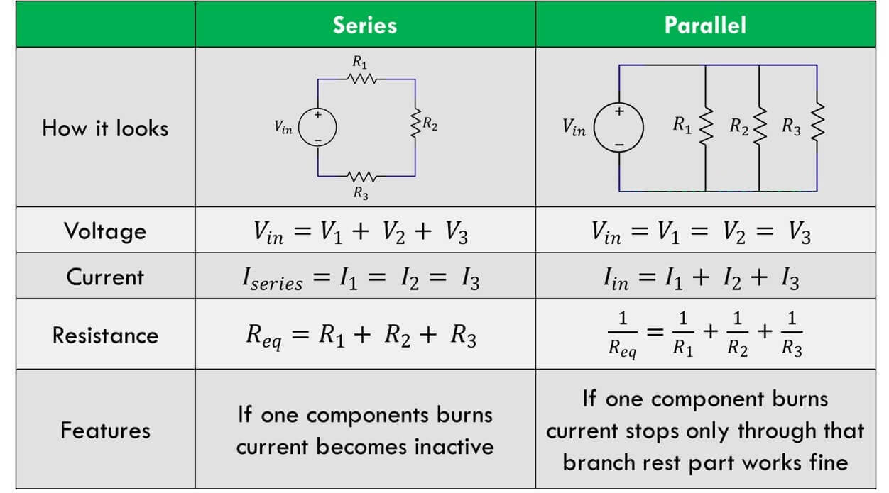
DC Series and Parallel Circuits
There are two different ways in which you can wire things together called series and parallel.
When things are wired in series, things are wired one after another, such that electricity has to pass through one thing, then the next thing, then the next, and so on.
When things are wired in parallel, they are wired side by side, such that electricity passes through all of them at the same time, from one common point to another common pointthings are wired one after another, such that electricity has to pass through one thing, then the next thing, then the next, and so on.
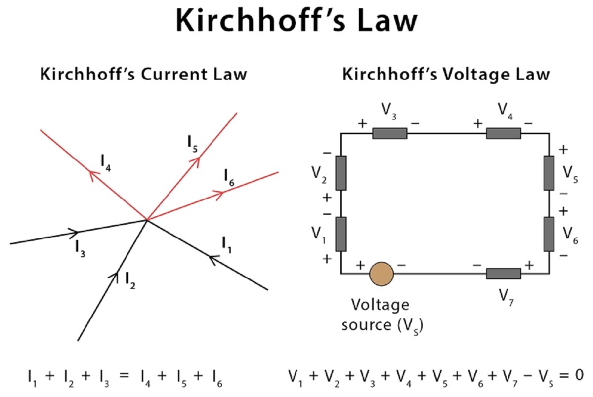
Kirchhoffs Circuit Laws
Kirchhoffs circuit laws lie at the heart of circuit analysis. With the help of these laws and the equation for individual components (resistor, capacitor and inductor), we have the basic tool to start analyzing circuits. The laws of Kirchhoff are the two equations that address conservation of energy and charge with reference to electrical circuits. They are very important in the analysis of closed and complex electrical circuits such as bridge or T networks in which calculating voltages or currents circulating within the circuit becomes difficult using Ohms law alone.
The advantages are: 1. Calculation of unknown currents and voltages is easy. 2. Simplification and analysis of complex closed loop circuits becomes manageable.
Kirchhoffs First Law or Kirchhoffs Current Law The total current entering a junction or a node is equal to the charge leaving the node as no charge is lost. Put differently, the algebraic sum of every current entering and leaving the node has to be null. This property of Kirchhoff law is commonly called Conservation of charge wherein, I(exit) + I(enter) = 0.
The term Node refers to a junction or a connection of two or more current-carrying routes like cables and other components. Kirchhoffs current law can also be applied to analyze parallel circuits.
Kirchhoffs Second Law or Kirchhoffs Voltage Law The voltage around a loop equals to the sum of every voltage drop in the same loop for any closed network and also equals to zero. Put differently, the algebraic sum of every voltage in the loop has to be equal to zero and this property of Kirchhoffs law is called conservation of energy.
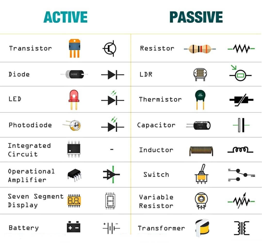
An electronic component is any physical entity in an electronic system used to affect the electrons or their associated fields in a manner consistent with the intended function of the electronic system. Components are generally intended to be connected together, usually by being soldered to a printed circuit board (PCB), to create an electronic circuit with a particular function (for example an amplifier, radio receiver, or oscillator). Components may be packaged singly, or in more complex groups as integrated circuits. Some common electronic components are capacitors, inductors, resistors, diodes, transistors, etc. Components are often categorized as active (e.g. transistors and thyristors) or passive (e.g. resistors, diodes, inductors and capacitors).
Active components vs Passive components
Basis
Active components
Passive components
Nature of source
Active components deliver power or energy to the circuit.
Passive elements utilizes power or energy from the circuit.
Examples
Diodes, Transistors, SCR, Integrated circuits etc.
Resistor, Capacitor, Inductor etc.
Function of the component
Devices which produce energy in the form of voltage or current
Devices which stores energy in the form of voltage or current
Power Gain
They are capable of providing power gain
They are incapable of providing power gain
Flow of current
Active components can control the flow of current
Passive components cannot control the flow of the current
Requirement of external source
They require an external source for the operations
They do not require any external source for the operations
Nature of energy
Active components are energy donor
Passive components are energy acceptor
Energy Storage
Cannot store the energy
Can store the energy (in case of inductor and capacitor)
Linearity
Normally non-linear
Fall under linear category mostly
Direction of operation
Unidirectional
Bidirectional
Acts as
Generators
Attenuators
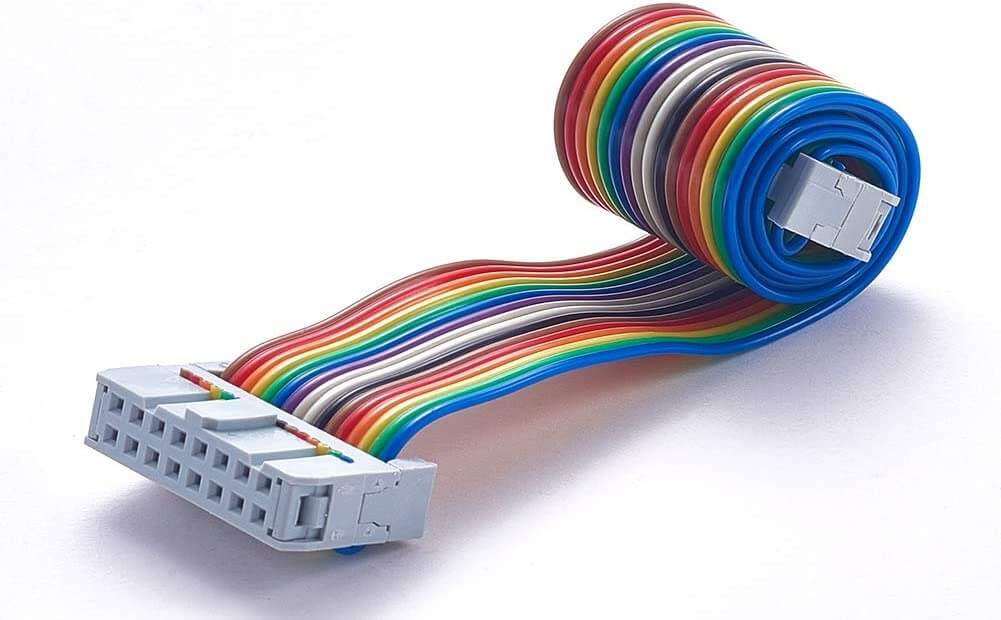
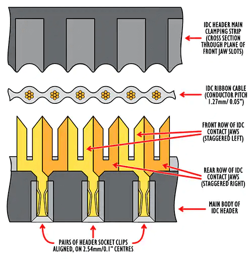
1. Ribbon Cable
A ribbon cable (also known as multi-wire planar cable) is a cable with many conducting wires running parallel to each other on the same flat plane. As a result, the cable is wide and flat. Its name comes from its resemblance to a piece of ribbon. Read More
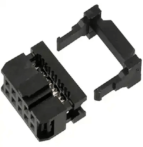
2. IDC Connector
An insulation-displacement contact (IDC), also known as insulation-piercing contact (IPC), is an electrical connector designed to be connected to the conductor(s) of an insulated cable by a connection process which forces a selectively sharpened blade or blades through the insulation, bypassing the need to strip the conductors of insulation before connecting. When properly made, the connector blade cold-welds to the conductor, making a theoretically reliable gas-tight connection. Read More
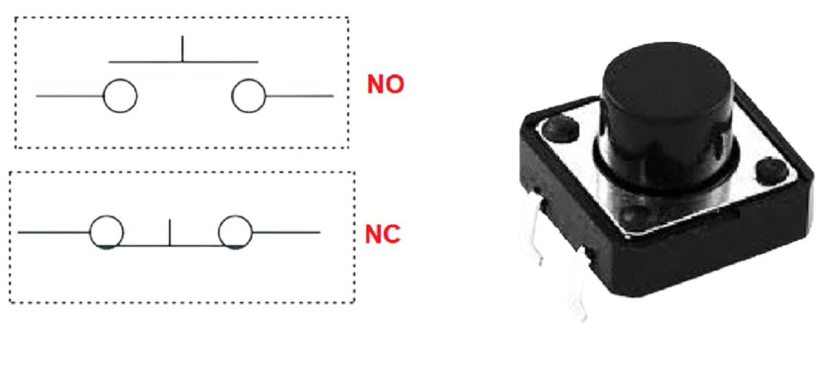
3. Push Buttons
Push-Buttons are normally-open tactile switches. Push buttons allow us to power the circuit or make any particular connection only when we press the button. Simply, it makes the circuit connected when pressed and breaks when released. Read More
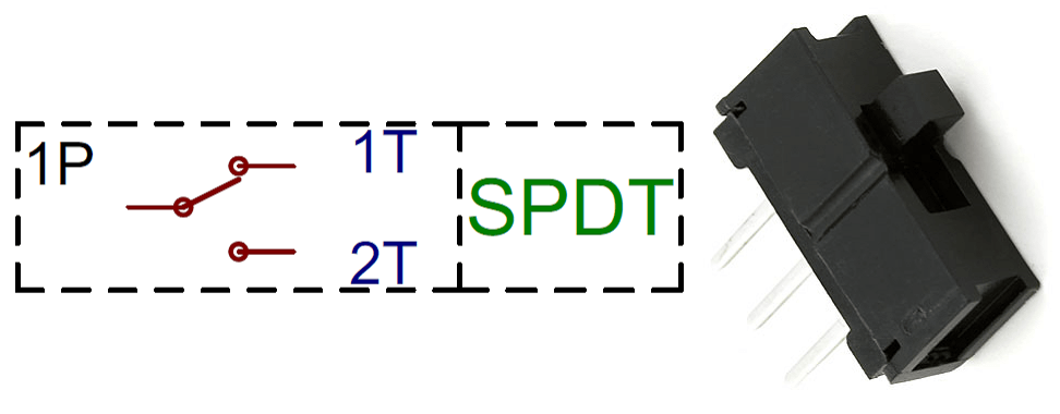
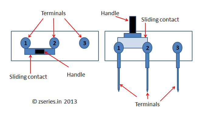
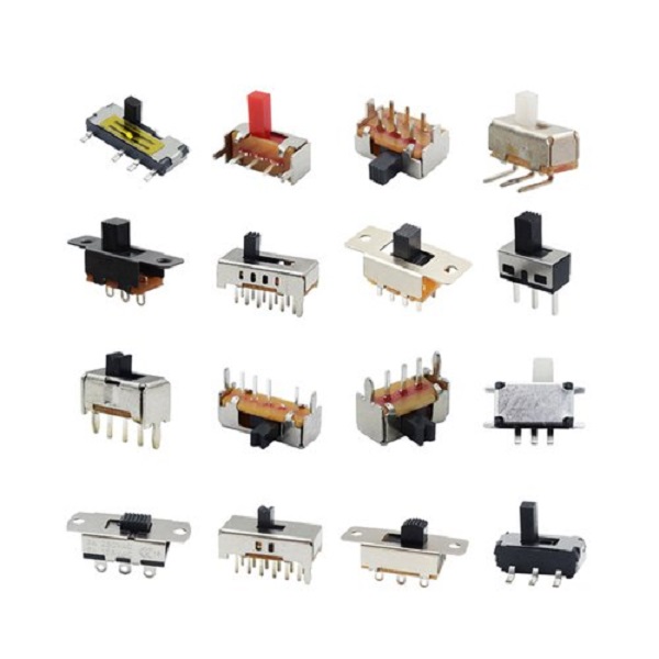
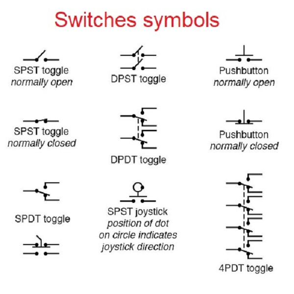
4. Switches
A switch is basically a mechanical device that creates a break in a circuit, interrupting the current or diverting it from one conductor to another. Electronic switches are considered binary devices because they can be on or off. When you activate the switch, it opens or closes the circuit. This is dependent on the type of switch it is. Read More
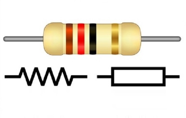
5. Resistors
A resistor is a passive two-terminal electrical component that implements electrical resistance as a circuit element. In electronic circuits, resistors are used to reduce current flow, adjust signal levels, to divide voltages, bias active elements, and terminate transmission lines, among other uses. For through-hole resistors, the different markings on the resistor represent different values of resistance. These values are measured in ohms. Resistors also come with different wattage ratings. For most low-voltage DC circuits, 1/4 watt resistors should be suitable. The behaviour of an ideal resistor is described by Ohm's law. The ohm is the SI unit of electrical resistance. Read More
Resistors basics
Calculations of Resistor value
6. Capacitors
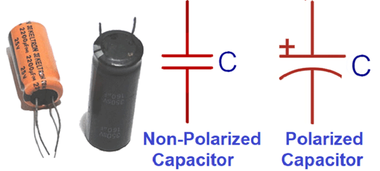
A capacitor is a component that stores electricity and then discharges it into the circuit when there is a drop in electricity. You can think of it as a water storage tank that releases water when there is a drought to ensure a steady stream. The effect of a capacitor is known as capacitance.
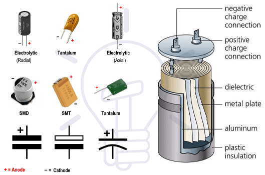
Capacitors are measured in Farads. The values that you will typically encounter in most capacitors are measured in picofarad (pF), nanofarad (nF), and microfarad (uF). The most commonly encountered types of capacitors are ceramic disc capacitors that look like tiny M&Ms with two wires sticking out of them and electrolytic capacitors that look more like small cylindrical tubes with two wires coming out the bottom (or sometimes each end).
Ceramic disc capacitors are non-polarized, meaning that electricity can pass through them no matter how they are inserted in the circuit. They are typically marked with a number code which needs to be decoded. Instructions for reading ceramic capacitors can be found here. This type of capacitor is typically represented in a schematic as two parallel lines.
Electrolytic capacitors are typically polarized. This means that one leg needs to be connected to the ground side of the circuit and the other leg must be connected to power. If it is connected backwards, it won't work correctly. Electrolytic capacitors have the value written on them, typically represented in uF. They also mark the leg which connects to ground with a minus symbol (-). This capacitor is represented in a schematic as a side-by-side straight and curved line. The straight line represents the end which connects to power and the curve connected to ground. Read More
Capacitors basics
Capacitor calculations in series and parallel
7. Crystal Oscillators, Resonators
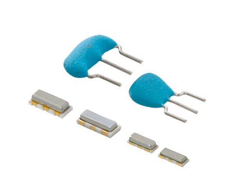
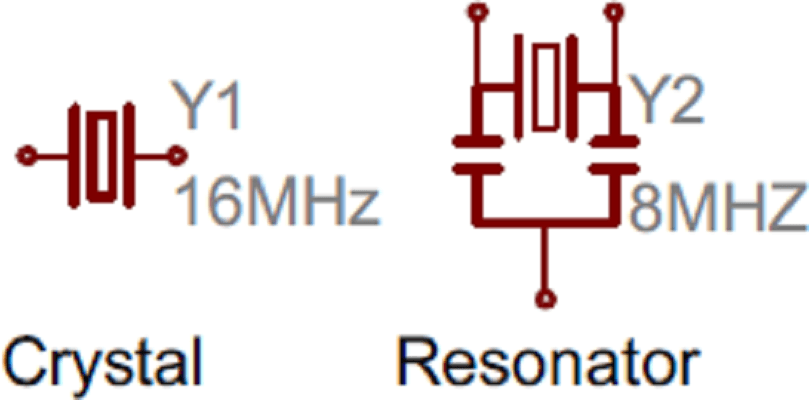
A crystal oscillator is an electronic oscillator that makes use of crystal as a frequency selective element to obtain an inverse piezoelectric effect. A crystal oscillator relies on the slight change in shape of a quartz crystal under an electric field, a property known as electrostriction or inverse piezoelectricity. A voltage applied to the electrodes on the crystal causes it to change shape; when the voltage is removed, the crystal generates a small voltage as it elastically returns to its original shape. The quartz oscillates at a stable resonant frequency, behaving like an RLC circuit. Read More
A crystal oscillator is an electric oscillator type circuit that uses a piezoelectric resonator, a crystal, as its frequency-determining element. Crystal is the common term used in electronics for the frequency-determining component, a wafer of quartz crystal or ceramic with electrodes connected to it. A more accurate term for it is piezoelectric resonator. Crystals are also used in other types of electronic circuits, such as crystal filters. Piezoelectric resonators are sold as separate components for use in crystal oscillator circuits. They are also often incorporated in a single package with the crystal oscillator circuit.
Resonator is a device which exhibits resonance property. It will oscillate at resonant frequencies. It has the highest frequency compared to others. The oscillations in resonator can be electromagnetic or mechanical. Resonators can be used to generate specific frequency waves. It can also used to select a particular frequency from the signal. A cavity resonator is the resonator which wave exists in hollow space inside the device. A system has many resonant frequencies. To generate specific frequency, mechanical resonators can be used in electronic circuits. Piezoelectric crystal is made from quartz which is used as frequency references. The mechanical resonators also used induce standing wave in other media. The electric circuit formed by electronic components such as inductor, capacitor etc. can act as a resonator. If the electronic components such as resistor, capacitor and inductor produce the resonator circuit, then this circuit is called RLC circuit. Read More
Oscillators basics
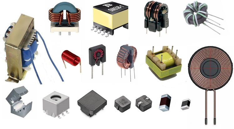
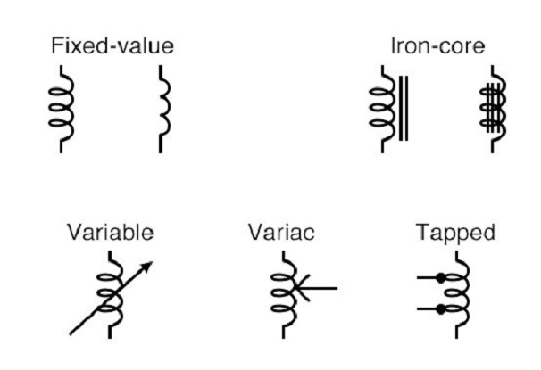
8. Inductors
An inductor, also called a coil, choke, or reactor, is a passive two-terminal electrical component that stores energy in a magnetic field when electric current flows through it. An inductor typically consists of an insulated wire wound into a coil.
When the current flowing through the coil changes, the time-varying magnetic field induces an electromotive force (e.m.f.) (voltage) in the conductor, described by Faradays law of induction. According to Lenz's law, the induced voltage has a polarity (direction) which opposes the change in current that created it. As a result, inductors oppose any changes in current through them.
An inductor is characterized by its inductance, which is the ratio of the voltage to the rate of change of current. In the International System of Units (SI), the unit of inductance is the henry (H) named for 19th century American scientist Joseph Henry. In the measurement of magnetic circuits, it is equivalent to weber/ampere. Inductors have values that typically range from 1 microH (10^-6 H) to 20 H. Read More
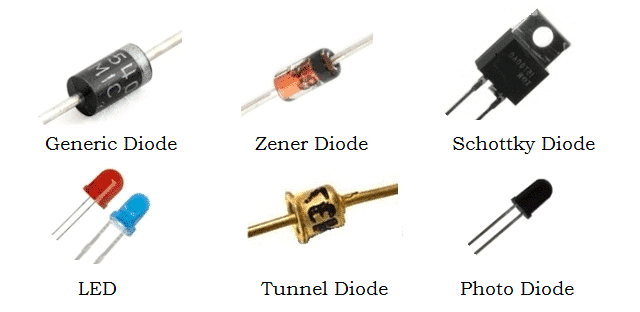
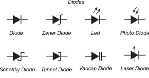
9. Diodes
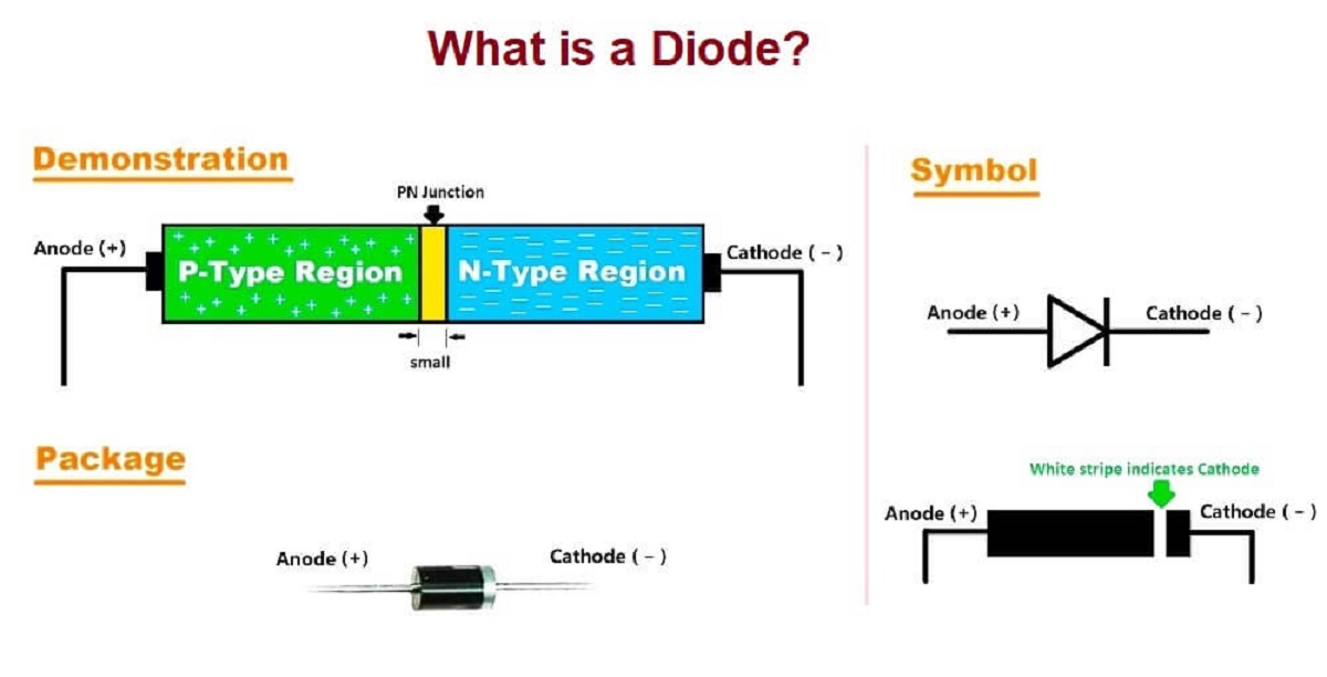
A semiconductor diode is a two terminal electronic component with a PN junction. This is also called as a Rectifier. The anode, which is the positive terminal of a diode is represented with A and the cathode, which is the negative terminal is represented with K. To know the anode and cathode of a practical diode, a fine line is drawn on the diode which means cathode, while the other end represents anode. A diode is used to block the electric current flow in one direction, i.e. allow current flow in forward direction and to block in reverse direction. We call this state forward-bias. Since the current can only flow in one direction (forward-bias), we unofficially think of diodes as one-way electronic valves. This principle of diode makes it work as a Rectifier. It protects our devices on the circuit from reverse polarity. The full-wave bridge rectifier using 4 diodes allow the current to flow through the components irrespective of the direction of current flow from power supply (e.g. when the source polarity has been changed accidently). It is used to covert AC to DV current.
Diodes Basics
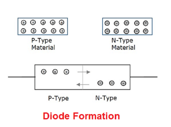
Formation of a Diode- If a P-type and an N-type material are brought close to each other, both of them join to form a junction, as shown in the left figure below.
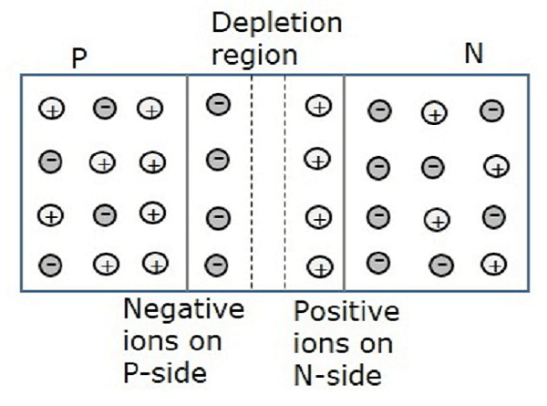
A P-type material has holes as the majority carriers and an N-type material has electrons as the majority carriers. As opposite charges attract, few holes in P-type tend to go to n-side, whereas few electrons in N-type tend to go to P-side. As both of them travel towards the junction, holes and electrons recombine with each other to neutralize and forms ions. Now, in this junction, there exists a region where the positive and negative ions are formed, called as PN junction or junction barrier as shown in the right figure below.
The formation of negative ions on P-side and positive ions on N-side results in the formation of a narrow charged region on either side of the PN junction. This region is now free from movable charge carriers. The ions present here have been stationary and maintain a region of space between them without any charge carriers. As this region acts as a barrier between P and N type materials, this is also called as Barrier junction. This has another name called as Depletion region meaning it depletes both the regions. There occurs a potential difference VD due to the formation of ions, across the junction called as Potential Barrier as it prevents further movement of holes and electrons through the junction.
Schottky Diode- It is like a normal PN diode, but its turning on voltage is very low, used in high frequency applications, where we have switch on-switch off at a high frequency. Zener diode- It works in both directions -ve to +ve, upto a zener voltage (till voltage reaches to zever voltage, after that it breaks down, its called avalanche break down). Why did we use zener diode in FabISP programmer near USB? It is to send and receive data from and to computer and chip.
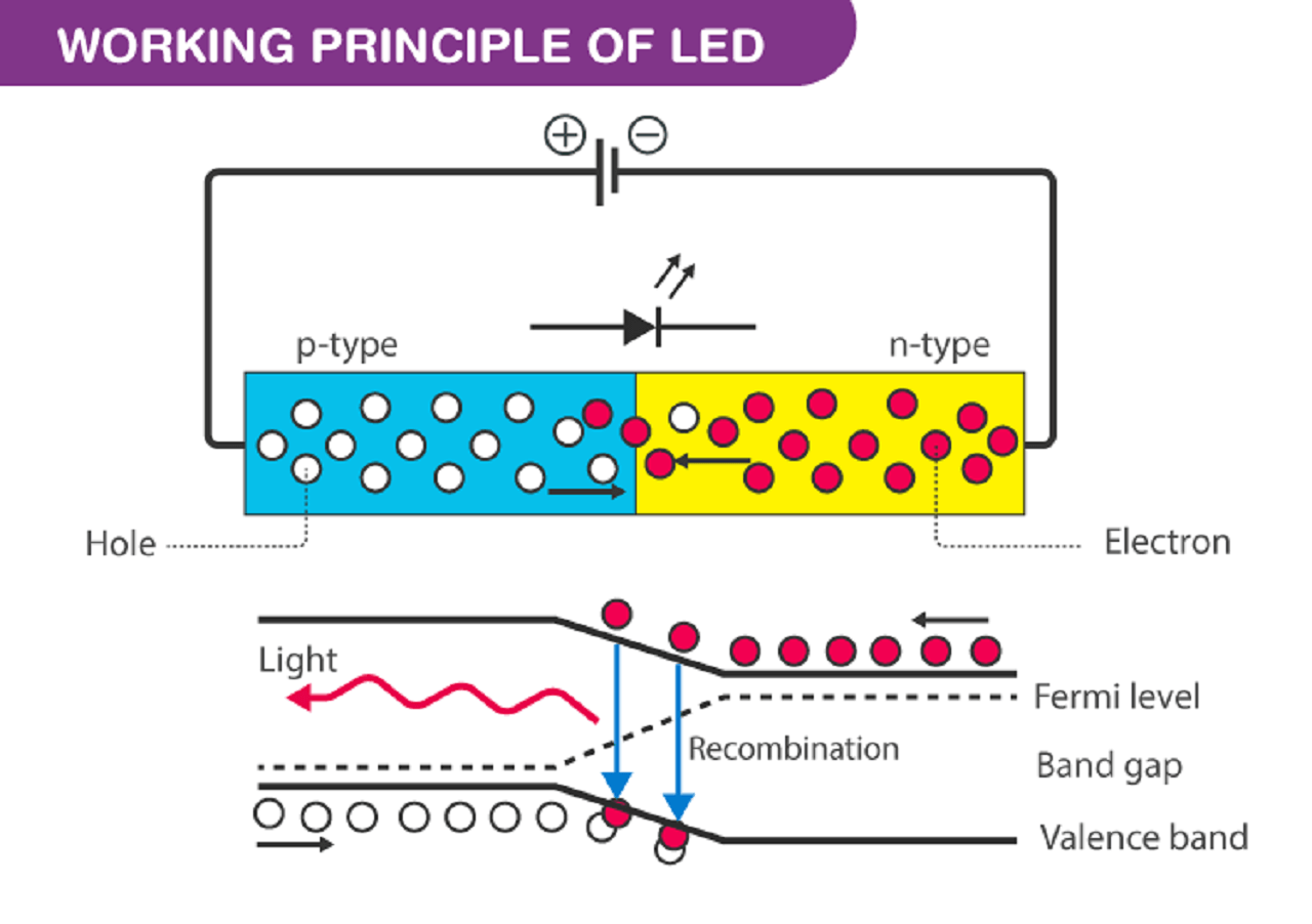
How LED works When the diode is forward biased, the minority electrons are sent from p to n while the minority holes are sent from n to p. At the junction boundary, the concentration of minority carriers increases. The excess minority carriers at the junction recombine with the majority charges carriers. The energy is released in the form of photons on recombination. In standard diodes, the energy is released in the form of heat. But in light-emitting diodes, the energy is released in the form of photons. We call this phenomenon electroluminescence. Electroluminescence is an optical phenomenon, and electrical phenomenon where a material emits light in response to an electric current passed through it. As the forward voltage increases, the intensity of the light increases and reaches a maximum.
Rectifier (AC to DC)- Diodes, Capacitors and DC Voltage Regulator
10. Transistors
A transistor is a semiconductor device used to amplify or switch electrical signals and power. The transistor is one of the basic building blocks of modern electronics. It is composed of semiconductor material, usually with at least three terminals for connection to an electronic circuit. A voltage or current applied to one pair of the transistor's terminals controls the current through another pair of terminals. Because the controlled (output) power can be higher than the controlling (input) power, a transistor can amplify a signal. Some transistors are packaged individually, but many more are found embedded in integrated circuits.
Most transistors are made from very pure silicon, and some from germanium, but certain other semiconductor materials are sometimes used. A transistor may have only one kind of charge carrier, in a field-effect transistor, or may have two kinds of charge carriers in bipolar junction transistor devices.
How does transistor work? A transistor can use a small signal applied between one pair of its terminals to control a much larger signal at another pair of terminals. This property is called gain. It can produce a stronger output signal, a voltage or current, which is proportional to a weaker input signal and thus, it can act as an amplifier. Alternatively, the transistor can be used to turn current on or off in a circuit as an electrically controlled switch, where the amount of current is determined by other circuit elements.
There are two types of transistors- Bipolar and Field-Effect Transistors, which have slight differences in how they are used in a circuit. A bipolar transistor has terminals labeled base, collector, and emitter. A small current at the base terminal (that is, flowing between the base and the emitter) can control or switch a much larger current between the collector and emitter terminals. For a field-effect transistor, the terminals are labeled gate, source, and drain, and a voltage at the gate can control a current between source and drain.
Transistor as a switch: Transistors are commonly used in digital circuits as electronic switches which can be either in an "on" or "off" state, both for high-power applications such as switched-mode power supplies and for low-power applications such as logic gates.
Transistor as an amplifier: The common-emitter amplifier is designed so that a small change in voltage (Vin) changes the small current through the base of the transistor whose current amplification combined with the properties of the circuit means that small swings in Vin produce large changes in Vout. From mobile phones to televisions, vast numbers of products include amplifiers for sound reproduction, radio transmission, and signal processing. The first discrete-transistor audio amplifiers barely supplied a few hundred milliwatts, but power and audio fidelity gradually increased as better transistors became available and amplifier architecture evolved. Read More
Transistor Basics
NPN and PNP Transistor
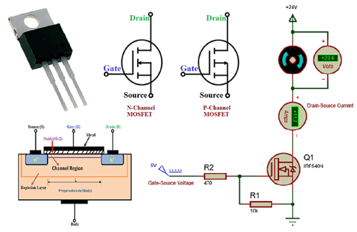
11. Mosfets
The metal-oxide-semiconductor field effect transistor (MOSFET, MOS-FET, or MOS FET), also known as the metal-oxide-silicon transistor (MOS transistor, or MOS), is a type of insulated-gate field-effect transistor that is fabricated by the controlled oxidation of a semiconductor, typically silicon. The voltage of the gate terminal determines the electrical conductivity of the device; this ability to change conductivity with the amount of applied voltage can be used for amplifying or switching electronic signals. Read More
Mosfet Basics
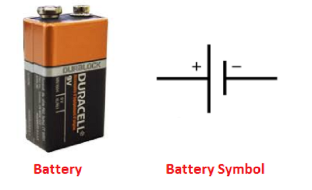
12. Battery
An electric battery is a source of electric power consisting of one or more electrochemical cells with external connections for powering electrical devices. To over-simplify the matter, you can say that it stores power.
When a battery is supplying power, its positive terminal is the cathode and its negative terminal is the anode. The terminal marked negative is the source of electrons that will flow through an external electric circuit to the positive terminal. When a battery is connected to an external electric load, a redox reaction converts high-energy reactants to lower-energy products, and the free-energy difference is delivered to the external circuit as electrical energy. Historically the term "battery" specifically referred to a device composed of multiple cells; however, the usage has evolved to include devices composed of a single cell.
Capacity of the Battery: The mAh capacity rating refers to the storage capacity available for a particular battery. A battery with a capacity rating of 1800 mAh could deliver a current of 1800mA for one hour. Higher mAh ratings for the same battery type will generally mean longer run times. Another way to measure the capacity of the battery is in Watt-hours (Wh). Wh is calculated by multiplying the number of Amps with the battery voltage. For example, a 12V100 (a 12 volt battery with a capacity of 100Ah) has a capacity of 12 x 100 = 1200Wh. A 24V50Ah battery has a capacity of 24 x 50 = 1200Wh.
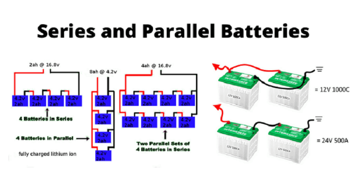
Batteries in Series By placing batteries in series you are adding the voltage of each consecutive battery, but the current stays the same. For instance, a AA-battery is 1.5V. If you put 3 in series, it would add up to 4.5V. If you were to add a fourth in series, it would then become 6V. Example2: When I have 5A/12V two batteries and when I want 5A/24V as output, I will connect 5A/12V two batteries in series.
Batteries in Parallel By placing batteries in parallel the voltage remains the same, but the amount of current available doubles. This is done much less frequently than placing batteries in series, and is usually only necessary when the circuit requires more current than a single series of batteries can offer. b>Example: When I have 5A/12V two batteries and when I want 10A/12V as output, I will connect 5A/12V two batteries in parallel. Read More
Battery Basics
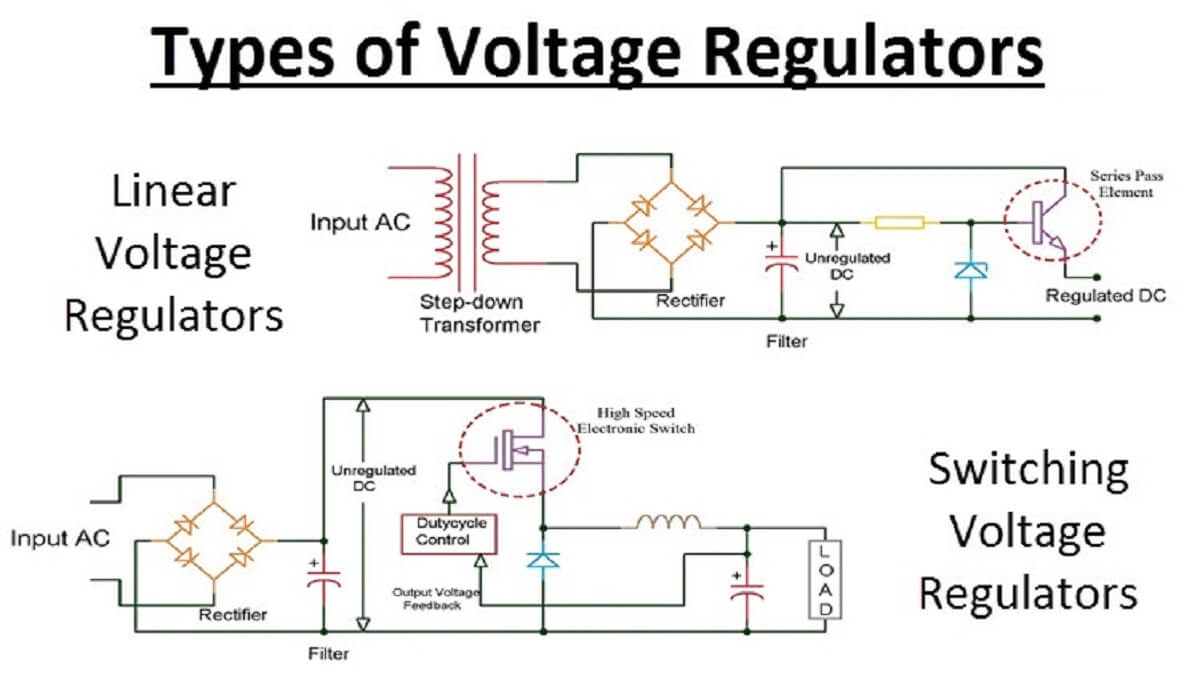
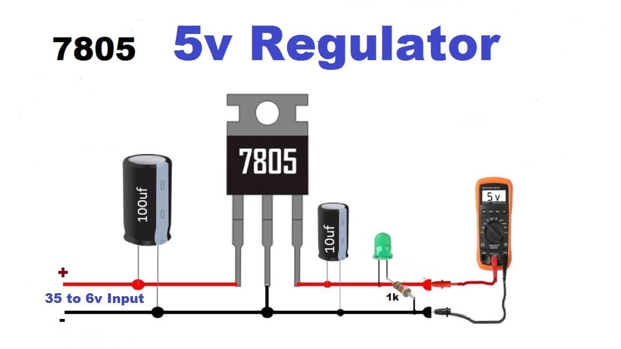
13. DC Voltage Regulators
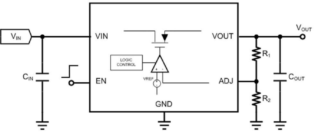
Voltage regulators are an essential part of most electronic hardware products. The function of a voltage regulator is to provide a stable voltage on the output of the regulator while the input voltage can be variable. Regulators (as well as battery chargers) can be broadly classified as linear or switching (Please see the image below). Since linear regulators are much easier understand we will start with them, and then move on to more complex switching regulators.
Linear Regulators: They can be thought of as variable resistance devices, where the internal resistance is varied in order to maintain a constant output voltage. In reality, the variable resistance is provided by means of a transistor controlled by an amplifier feedback loop. Linear regulators normally consist of a minimal of three pins- an input input, an output pin, and a ground pin. External capacitors are placed on the input and output terminals to provide filtering and to improve the transient response to sudden load changes. The output capacitor is also required for stability of the voltage regulators feedback loop. (Please see the images below).
The amount of current flowing through the regulator, and the amount of power dissipated in the device, will influence the device package selection and heat sink requirements. Linear regulators are much less efficient than switching regulators and therefore waste more power which dissipates as heat.
Linear regulators require an input voltage that is higher than the output. The minimum voltage level difference between the input and the output is called the dropout voltage. For a normal linear voltage regulator the dropout is about 2 volts. Low dropout (LDO) regulators can regulate down to less than 100mV. However, their ability to reject noise and ripple on the input supply will be significantly reduced below about 500mV. For most applications a linear regulator, or more specifically a LDO regulator, makes more sense if the input voltage is no more than a couple volts above the output voltage. Otherwise, the regulator will waste too much power and a more efficient switching regulator is a better option. Linear regulators have three main advantages: They are simple, cheap, and provide exceptionally "clean" voltage outputs.
Linear Regulator Basics
How to use Linear Regulator in circuits
Switching Regulators: Switching regulators convert one voltage to another by temporarily storing energy and then releasing that stored energy to the output at a different voltage. The terms DC to DC converter, switched mode power supply (SMPS), switching regulator, and switching converter all refer to the same thing. These operate by controlling a solid state device, like a transistor or diode, that acts like a switch. The switch interrupts the flow of current to an energy storage component, such as a capacitor or an inductor, in order to transform one voltage to another.
Buck/Boost (Step-Down/Up) Type Switching Regulators: A buck/boost converter, as you might have guessed, is capable of supplying a fixed output voltage from an input voltage that can vary above and below the output voltage. This type of a voltage regulator is very useful in battery operated equipment, where the input voltage decreases with time.
Switching Regulators Basics
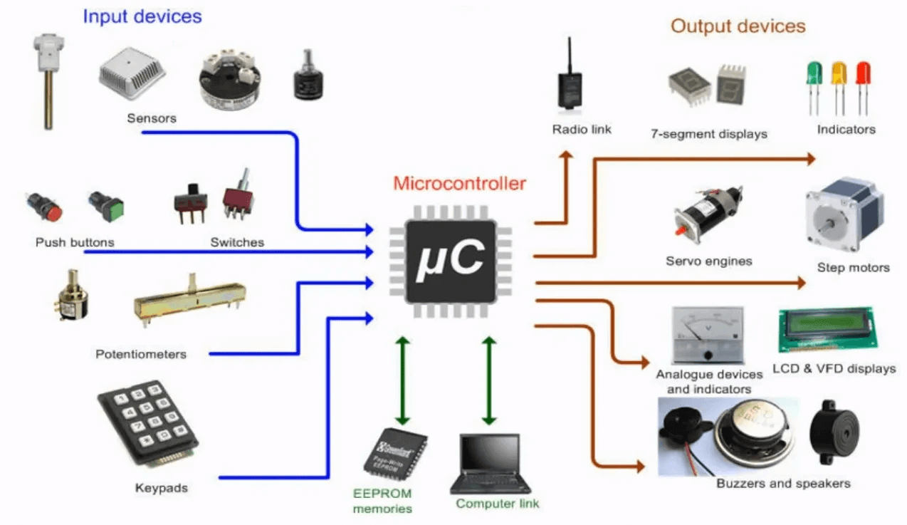
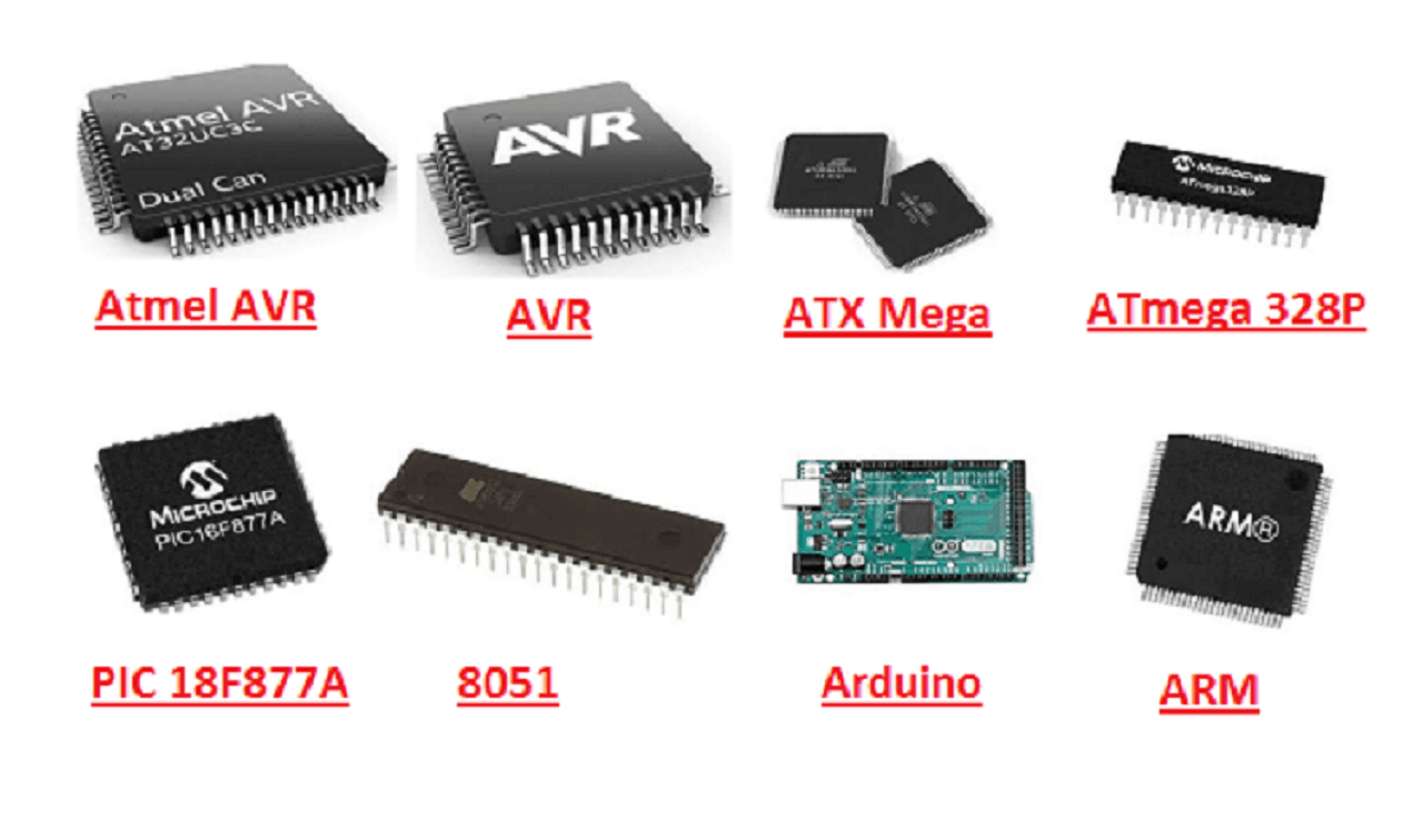
14. Microcontroller
A microcontroller (MCU for microcontroller unit) is a small computer on a single metal-oxide-semiconductor (MOS) integrated circuit (IC) chip. A microcontroller contains one or more CPUs (processor cores) along with clock, Digital to Analog Converter (DAC), Analog to Digital Converter (ADC), memory and programmable input/output peripherals. Program memory in the form of ferroelectric RAM, NOR flash or OTP ROM is also often included on chip, as well as a small amount of RAM. Microcontrollers are designed for embedded applications, in contrast to the microprocessors used in personal computers or other general purpose applications consisting of various discrete chips.
In modern terminology, a microcontroller is similar to, but less sophisticated than, a system on a chip (SoC). An SoC may include a microcontroller as one of its components, but usually integrates it with advanced peripherals like a graphics processing unit (GPU), a Wi-Fi module, or one or more coprocessors. Microcontrollers are used in automatically controlled products and devices, such as automobile engine control systems, implantable medical devices, remote controls, office machines, appliances, power tools, toys and other embedded systems. By reducing the size and cost compared to a design that uses a separate microprocessor, memory, and input/output devices, microcontrollers make it economical to digitally control even more devices and processes. Mixed signal microcontrollers are common, integrating analog components needed to control non-digital electronic systems. In the context of the internet of things, microcontrollers are an economical and popular means of data collection, sensing and actuating the physical world as edge devices.
Difference between microcontroller and microprocessor
15. Sensors
A sensor is a device that produces an output signal for the purpose of sensing of a physical phenomenon. In the broadest definition, a sensor is a device, module, machine, or subsystem that detects events or changes in its environment and sends the information to other electronics, frequently a computer processor. Sensors are always used with other electronics. We will see more details about sensors in Input devices week.
16. Actuators
In electronic engineering, actuators are a subdivision of transducers. They are devices which transform an input signal (mainly an electrical signal) into some form of motion. We will see more details about sensors in Output devices week.
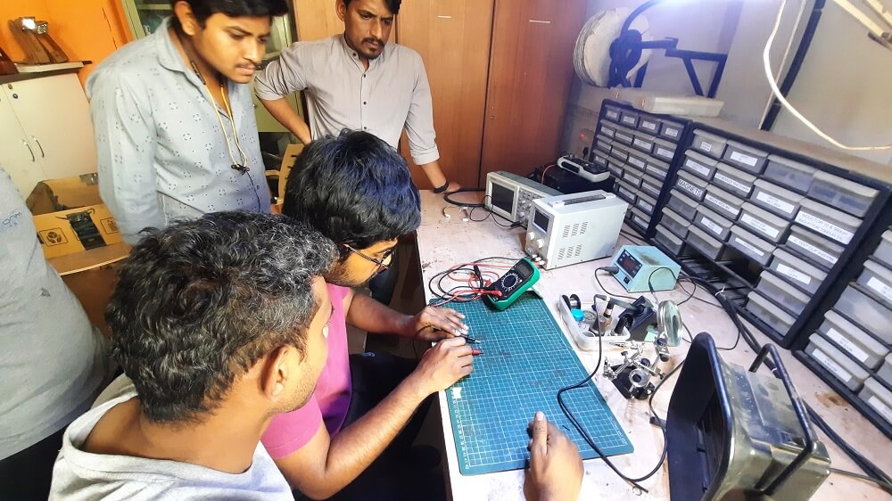
This assignment is about documenting what we learned in Electronics Design week that includes working on test equipment in our lab to observe the operation of one of the echo Hello world boards that we designed this week in our Individual assignment. We checked the operating voltage on the board with a multimeter and used an oscilloscope in our lab to check different waveforms the board was generating at different points in the circuit. We also observed the noise in operating voltage and interpret a signal of blinking LED on the board. We used the variable power supplier in the lab to find out how much current the board is consuming and what is the operating voltage for LEDs.
Objectives of the Group Assignment:
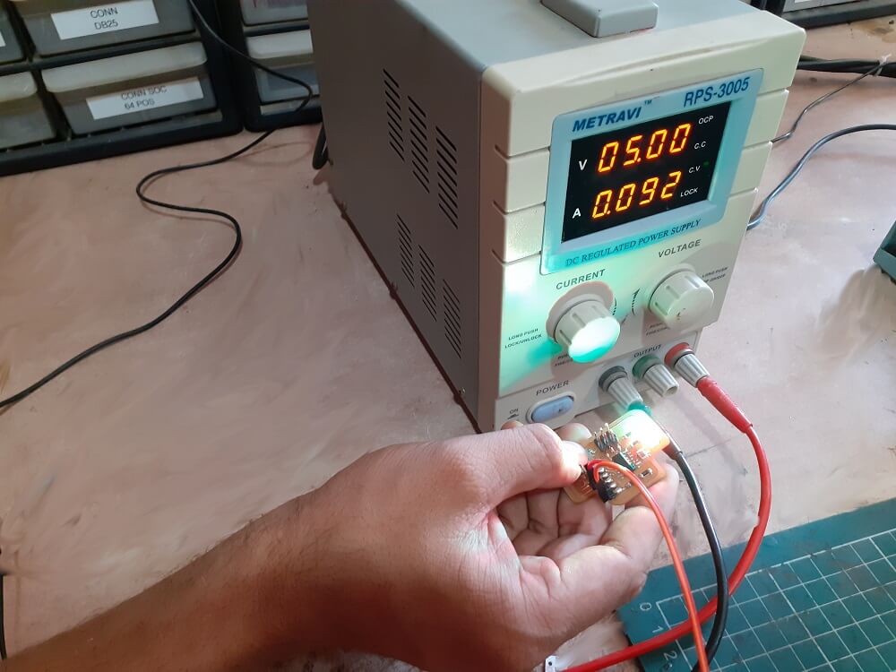
- Understand and use the power supply unit for powering the echo Hello World board
- Understand and use Multimeter to test properties of echo Hello World board such as Continuity, Resistance, voltage,current supply, etc.
- Understand and use Digital Storage Oscilloscope (DSO) to observe the waveforms, check noise of operating voltage and interpret a signal of blinking LED.
Equipment need to be Tested:
- Multimeter
- Variable Power Supply
- Digital Storage Oscilloscope
Using the test equipment in our lab
So we tested the above devices one by one and observed the operation of a microcontroller circuit board using these test equipment available in our Fab lab at Vigyan Ashram.
- Redraw an echo Hello-world board
- Add (at least) a button and LED (with current-limiting resistor)
- Check the design rules, make it, and test that it can communicate
- Extra credit: simulate its operation
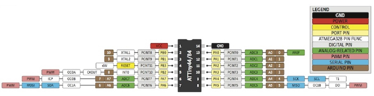
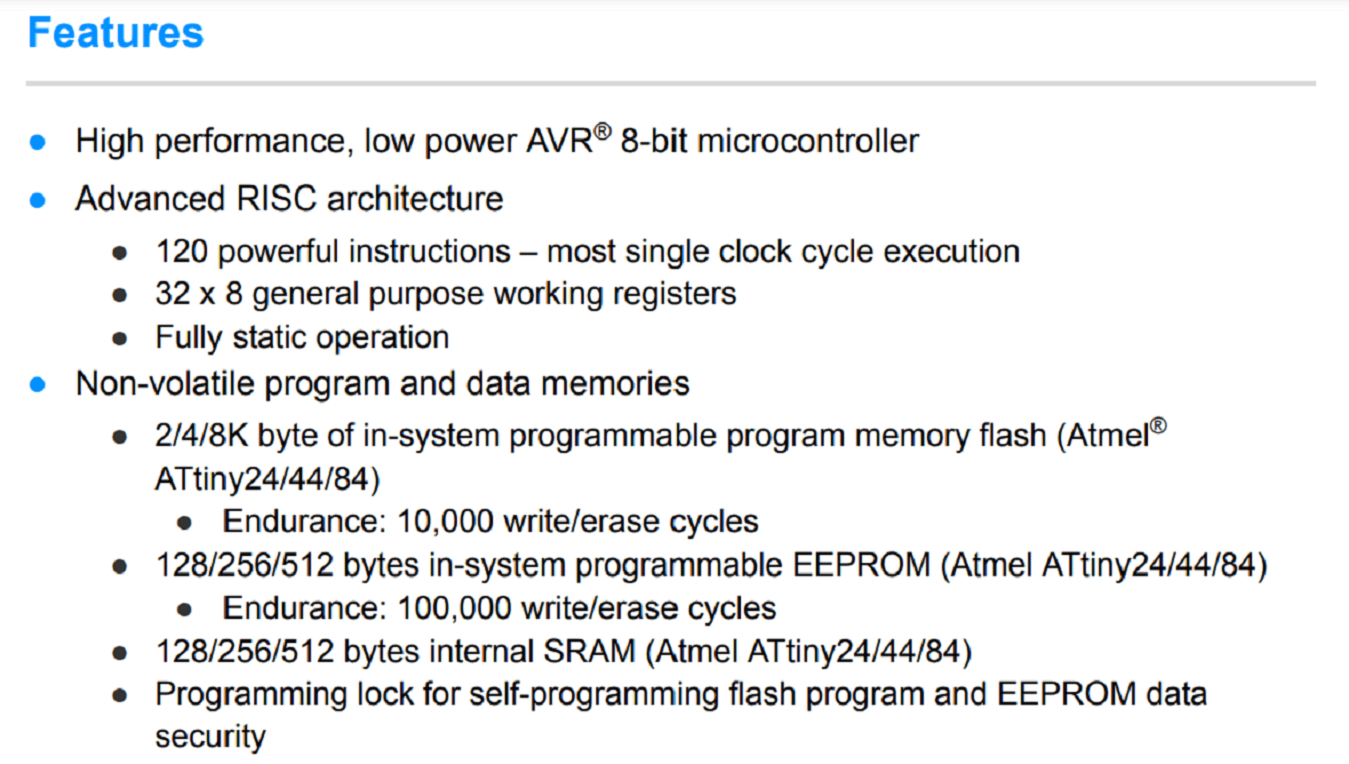
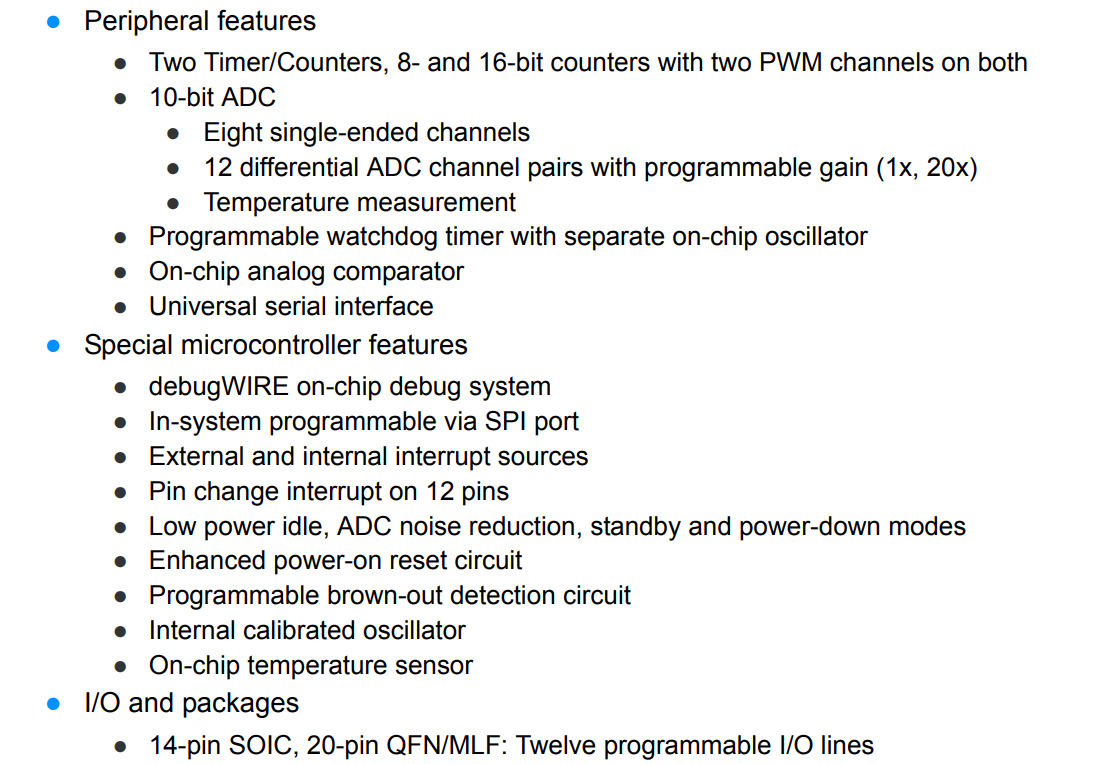
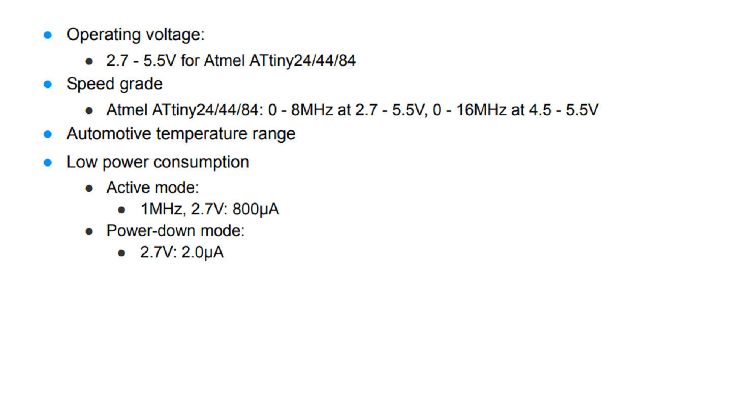
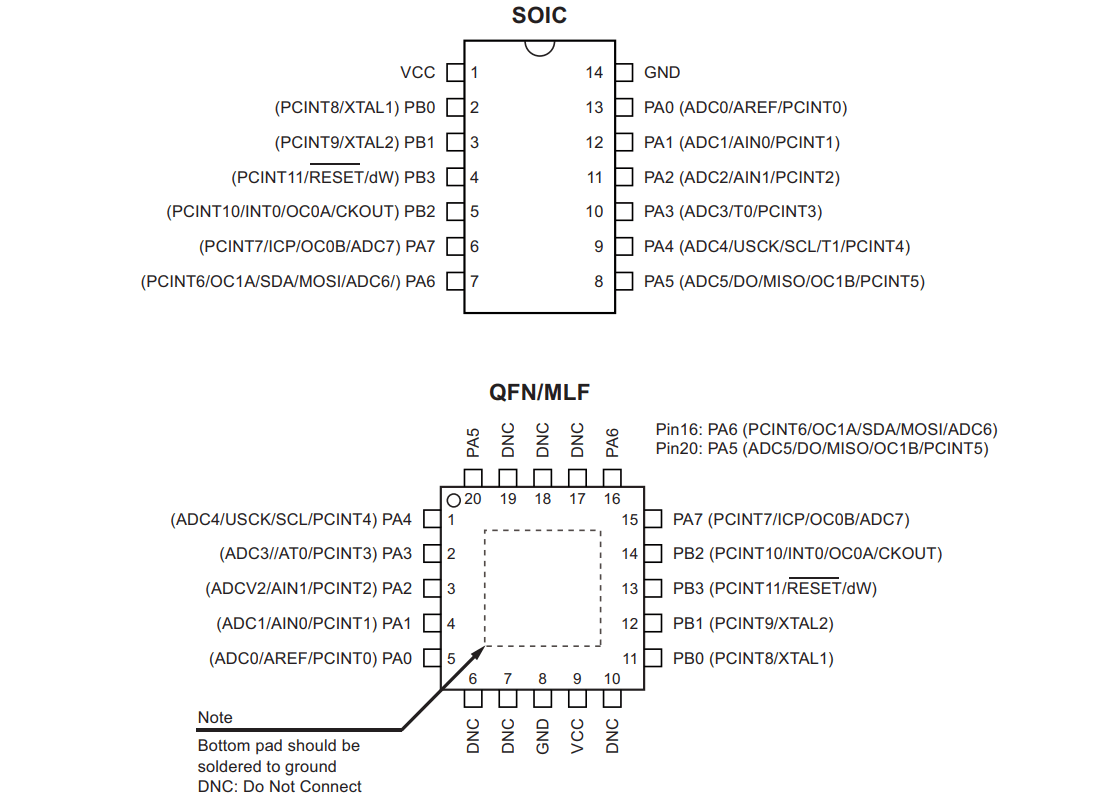
ATtiny (also known as TinyAVR) are a subfamily of the popular 8-bit AVR microcontrollers, which typically has fewer features, fewer I/O pins, and less memory than other AVR series chips Read more. Download Datasheet of ATTiny44 by clicking here.
Pinout and Features of ATTiny44:
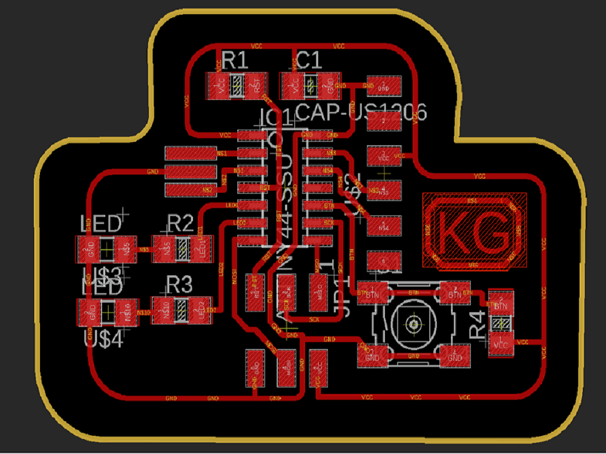
Designing Echo Hello-world Board
I used Eagle software to design the schematic and board files for my Echo Hello-world Board. In case, you do not have Eagle installed, download it from here. The Eagle UI looks like this:
Step 1: Before I started designing my board, I added Fab library of components to the application so that I can use these components for my PCB. Search fab academy library in Google.
Click on Download Zip file and unzip the folder before we move further.
Open Eagle software and Click Library and go to Open library manager menu inside it as shown below.
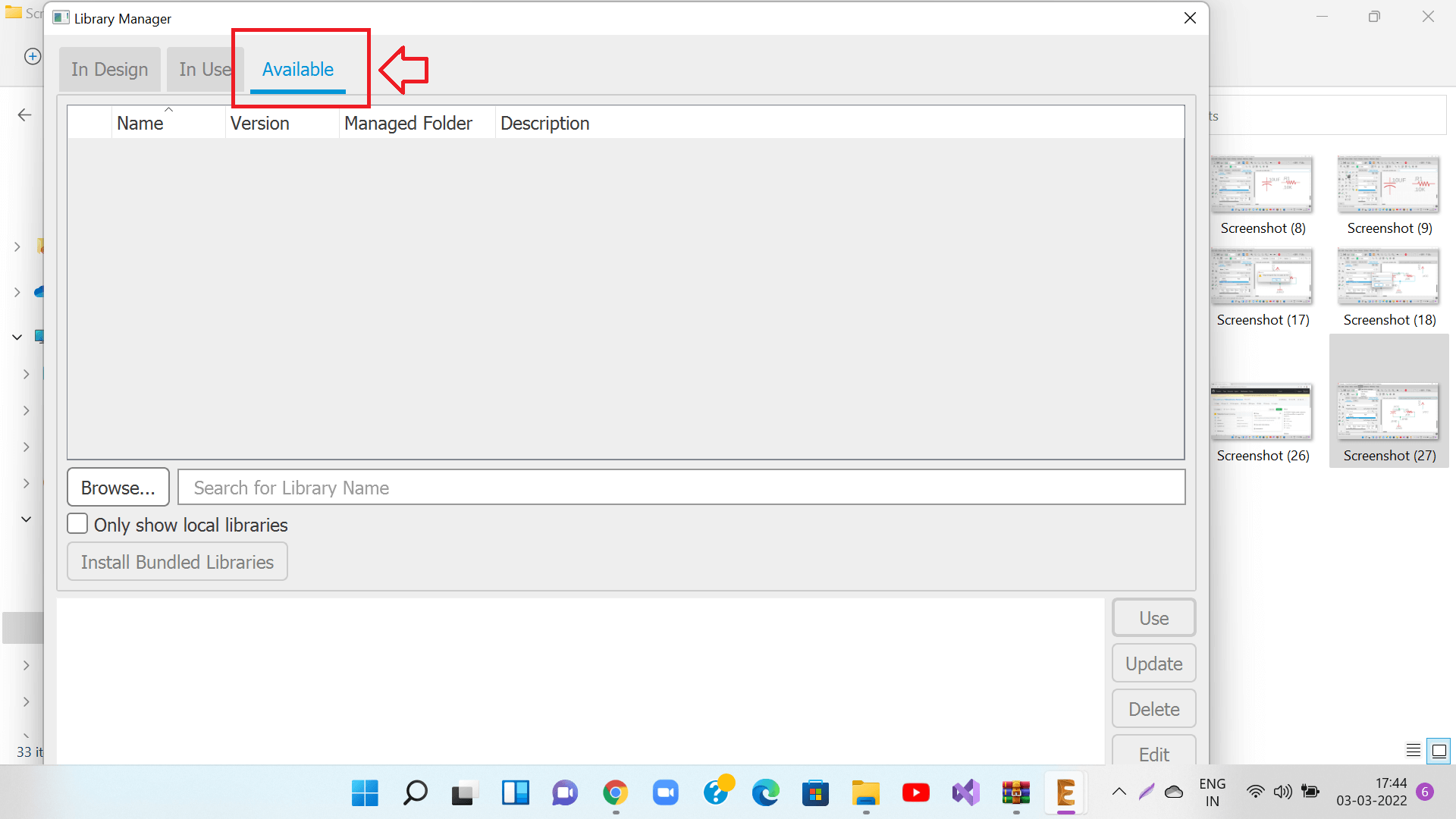
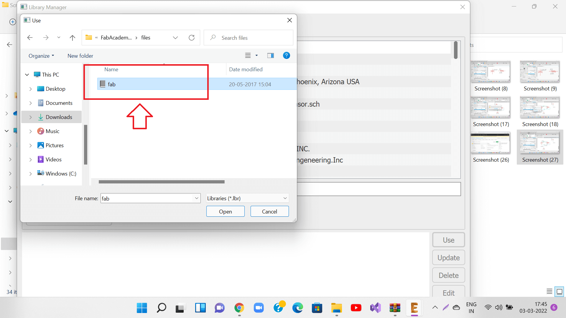
Once inside the 'Available' tab of library manager, Click Browse to pull in the unzipped library file that we just had downloaded.
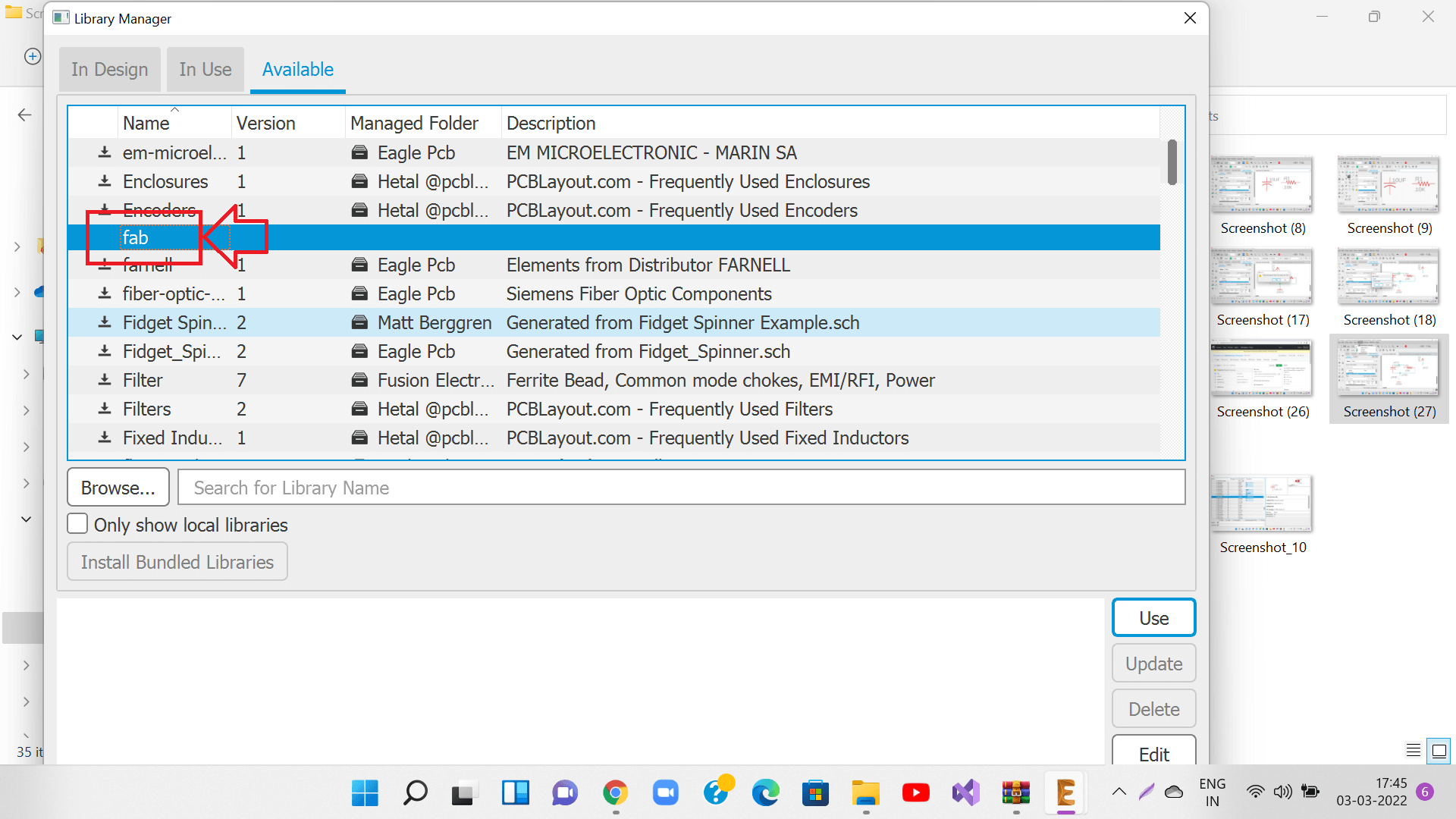
Done. After the fab library is imported, you will see it inside the Available tab now.
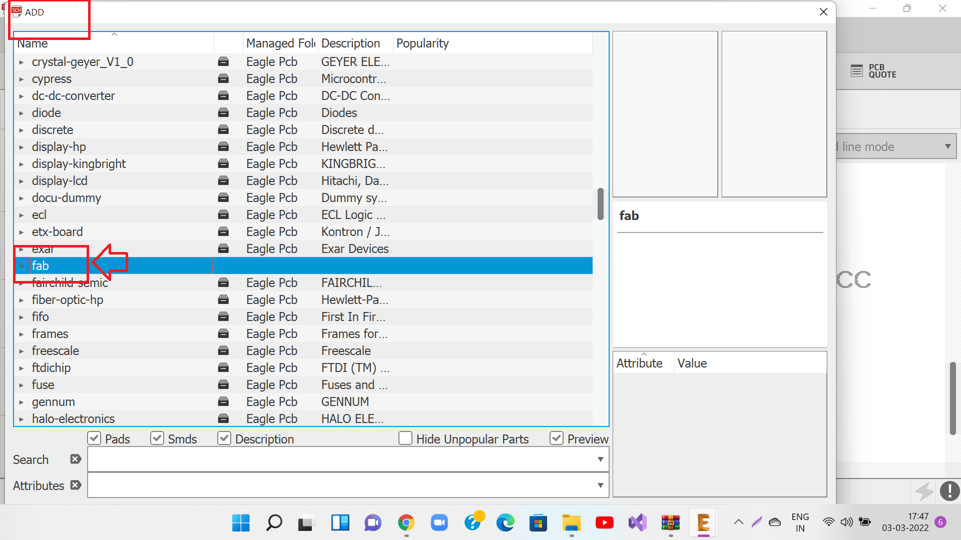
Good job :-) You will also see Fab library, when you will start adding components inside a schematic diagram in Eagle as shown below.
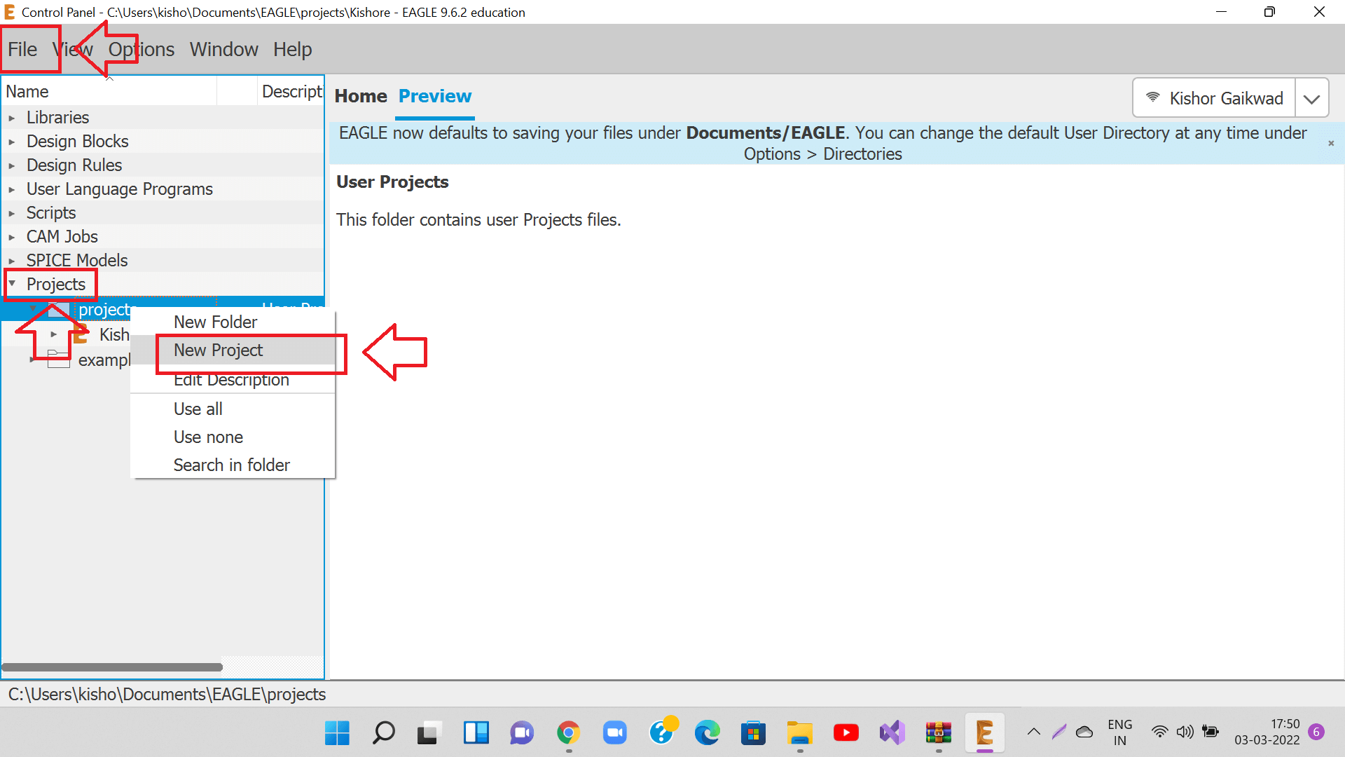
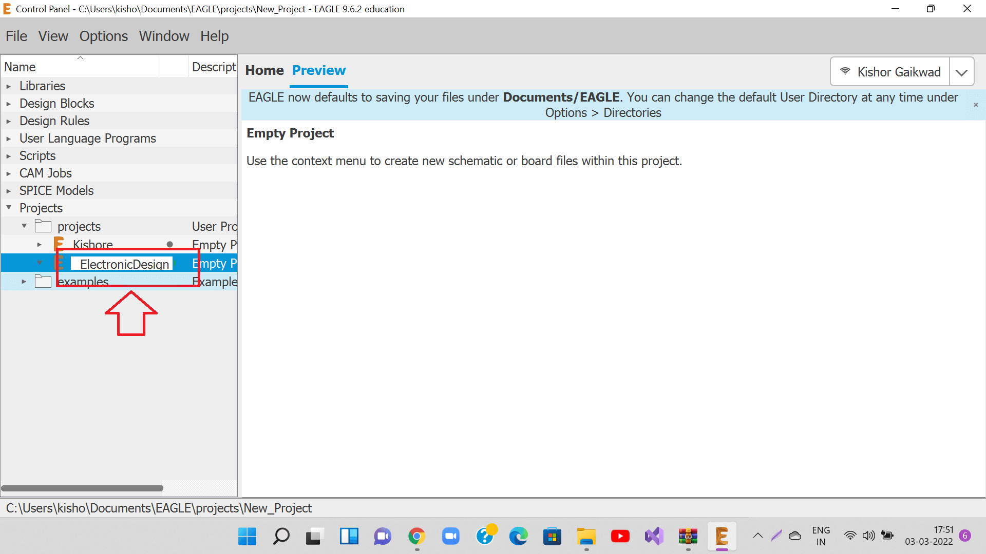
Go to File- Projects- New Projects and create a new project with a desired name.as shown in the images below.
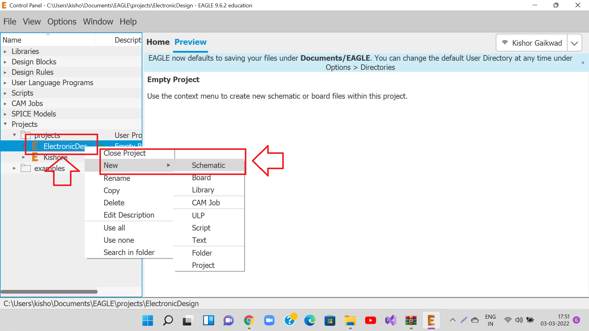
Right click on the newly created project and create a new schematic as shown in the image below.
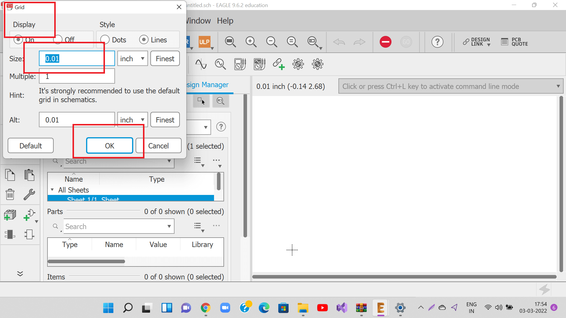
Once inside the new schematic, click on 'Grid' and adjust the grid size to be as small as 0.01 inch so that we can draw and route traces very precisely.
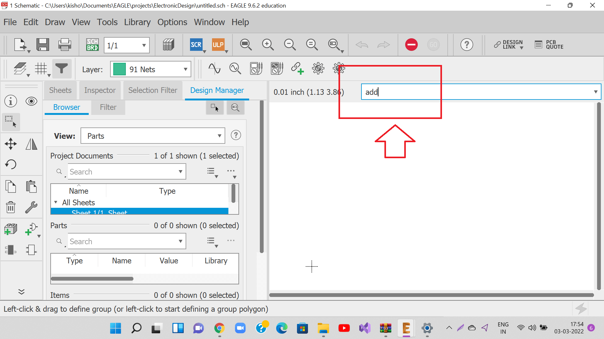
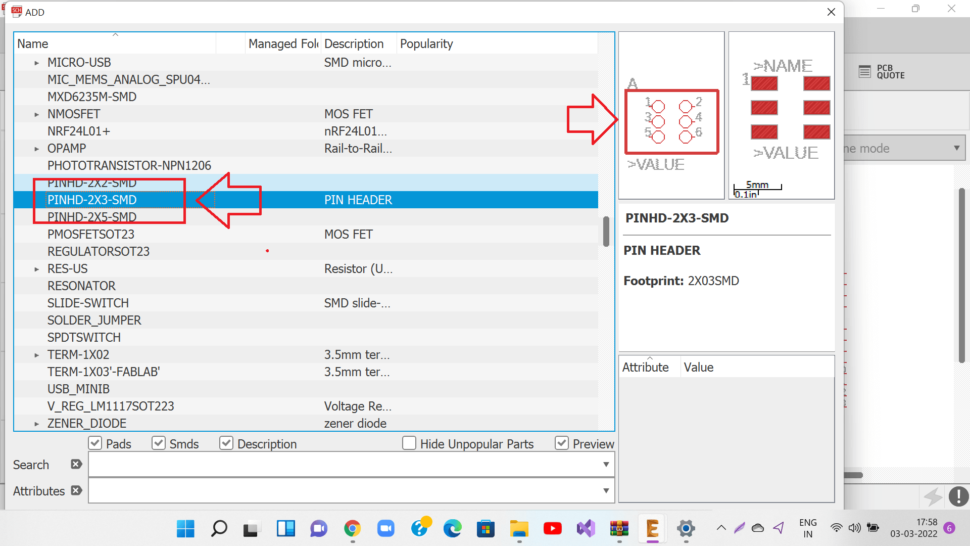
Start the schematic by adding desired components as per the board design either by click add button or giving add command.
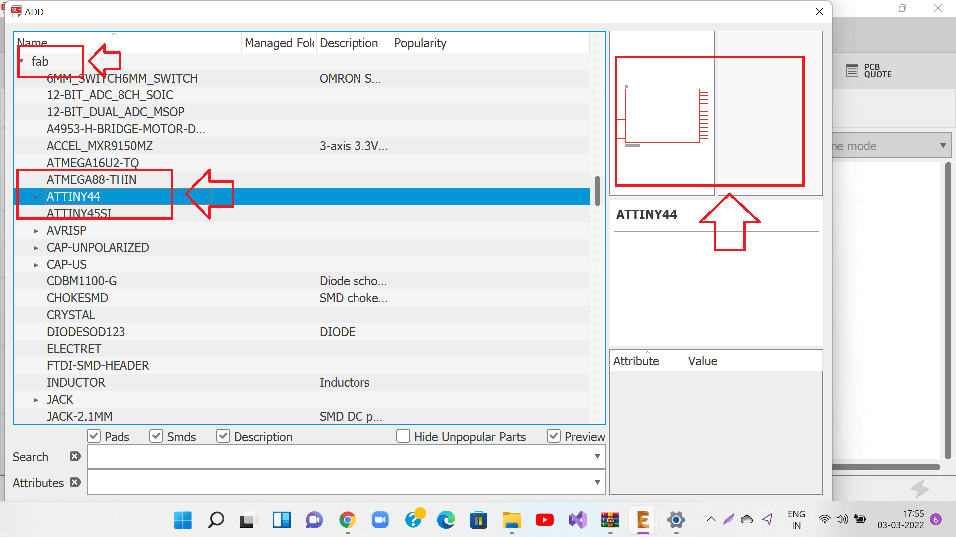
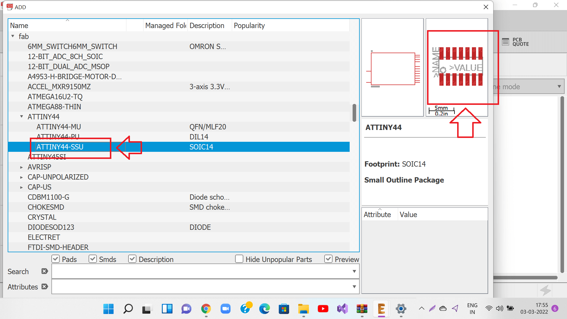
Add ATTiny44 from the Fab library
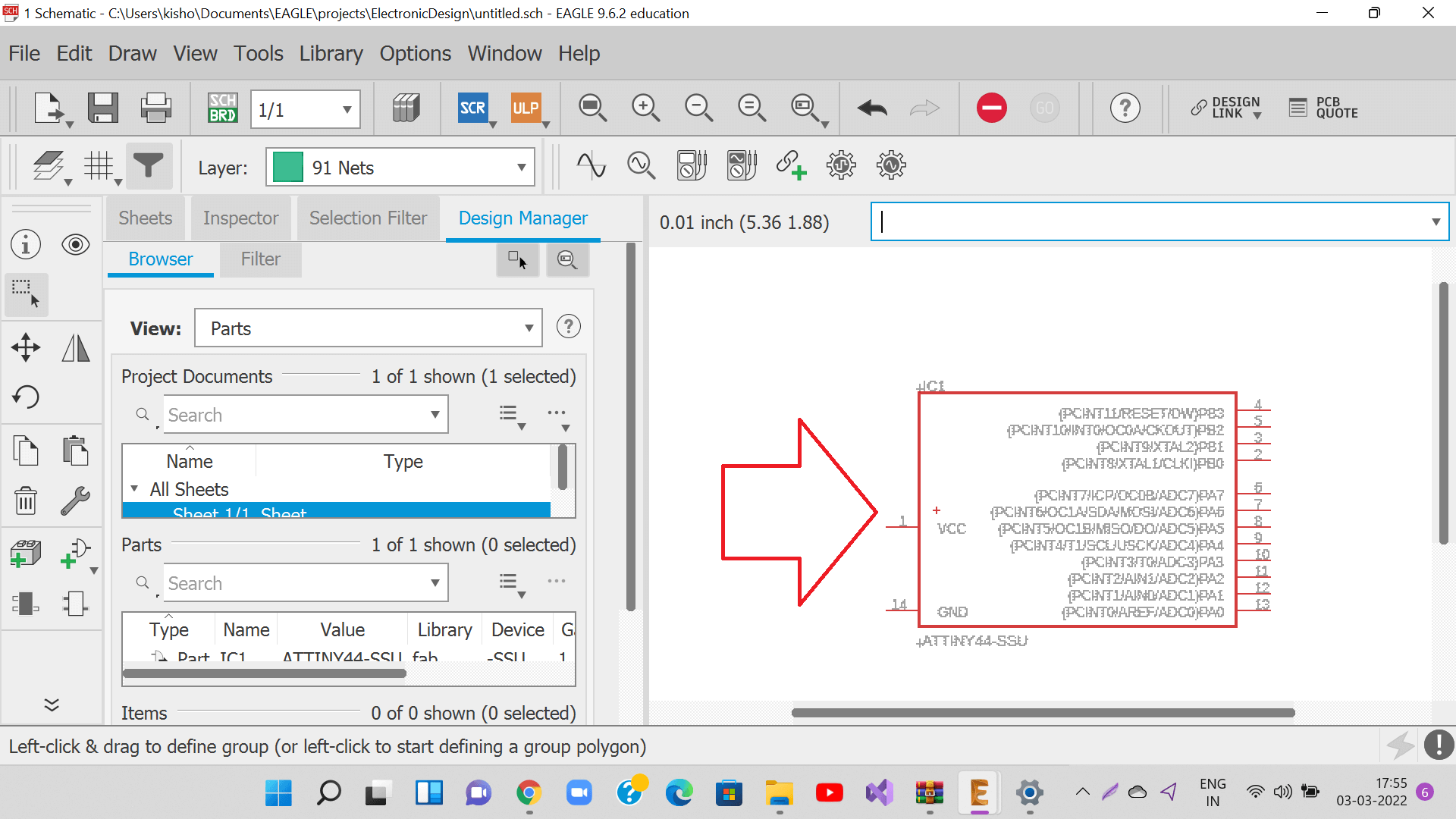
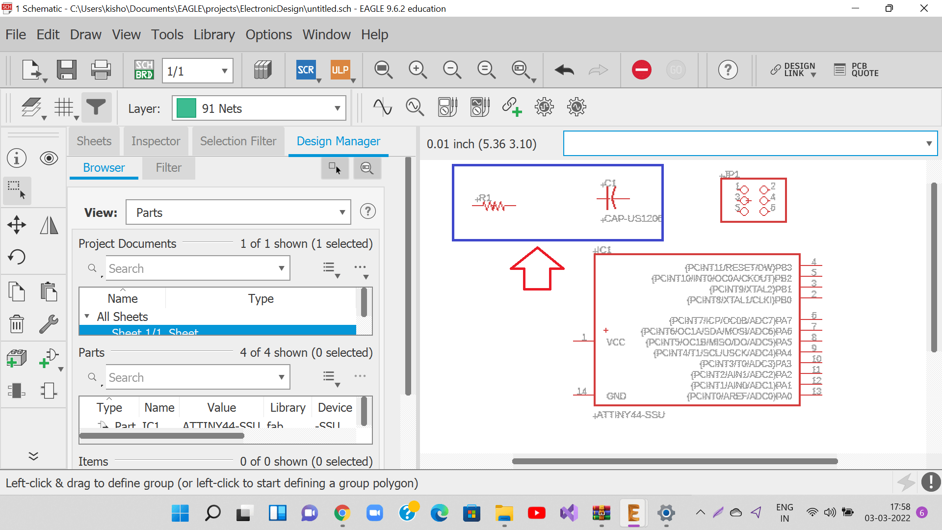
Place ATTiny44 inside the schematic
Add all other components as per the components list from the Fab library
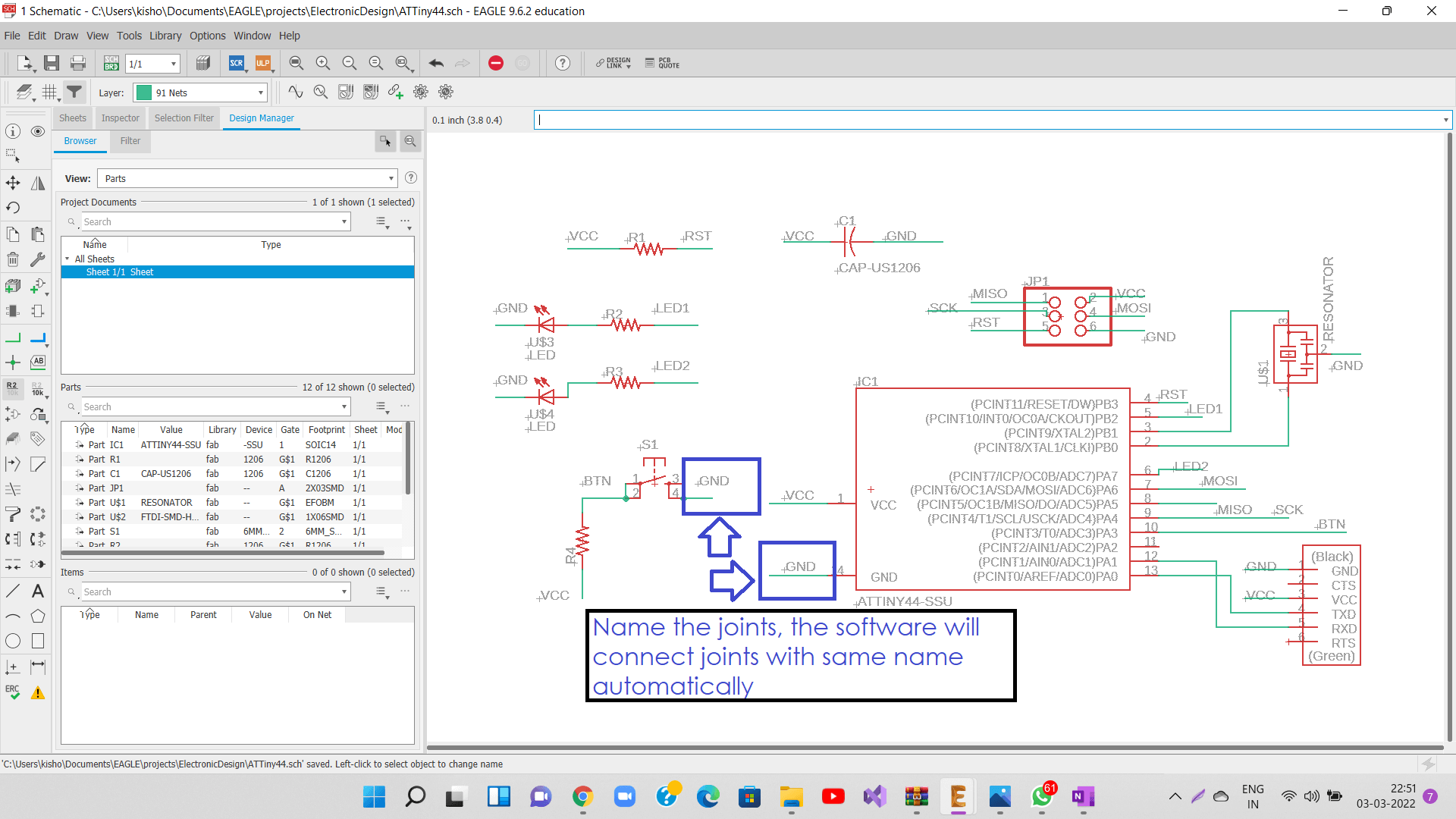
Name the connecting lines by right clicking on it. We can name the connecting line on other components to be same if we want to connect these two lines. Eagle will ask us if they are connected them since their names are same. We do not need to draw lines in the schematic.
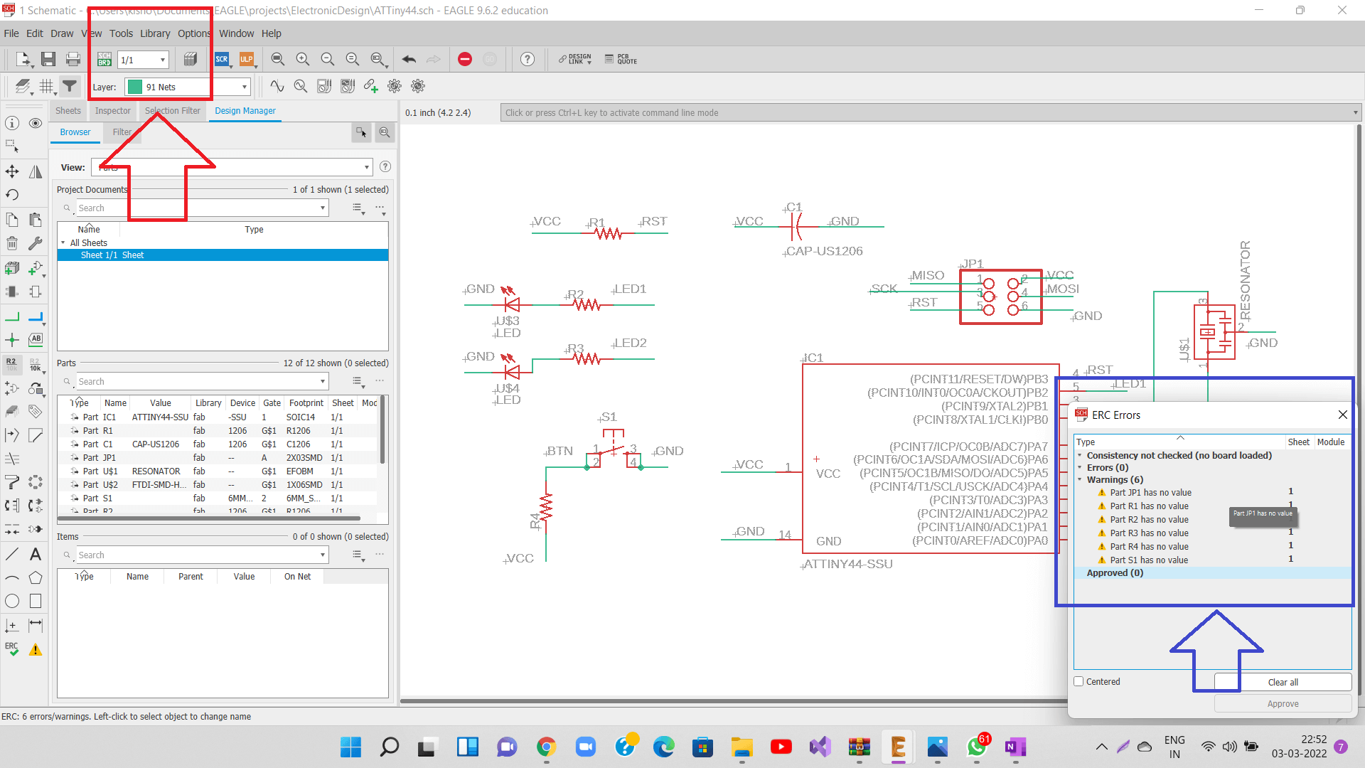
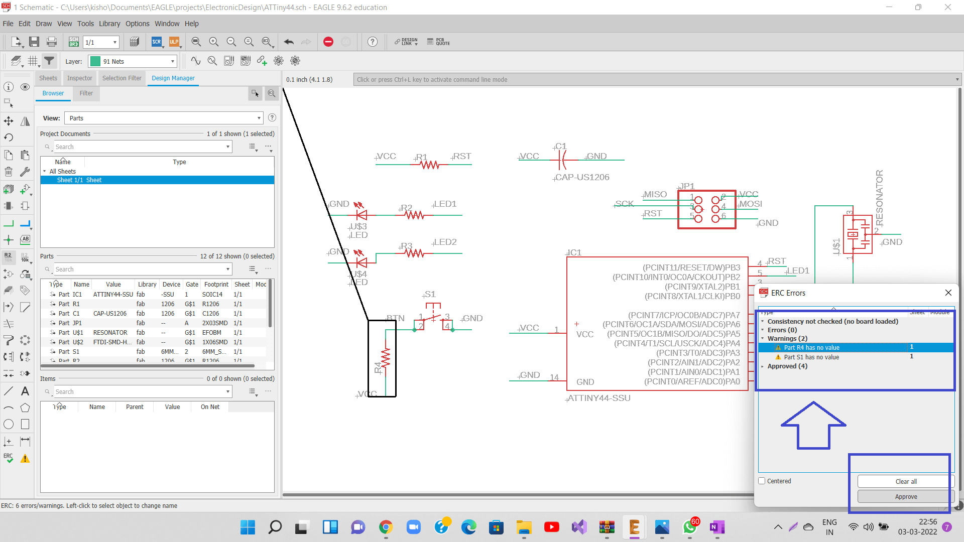
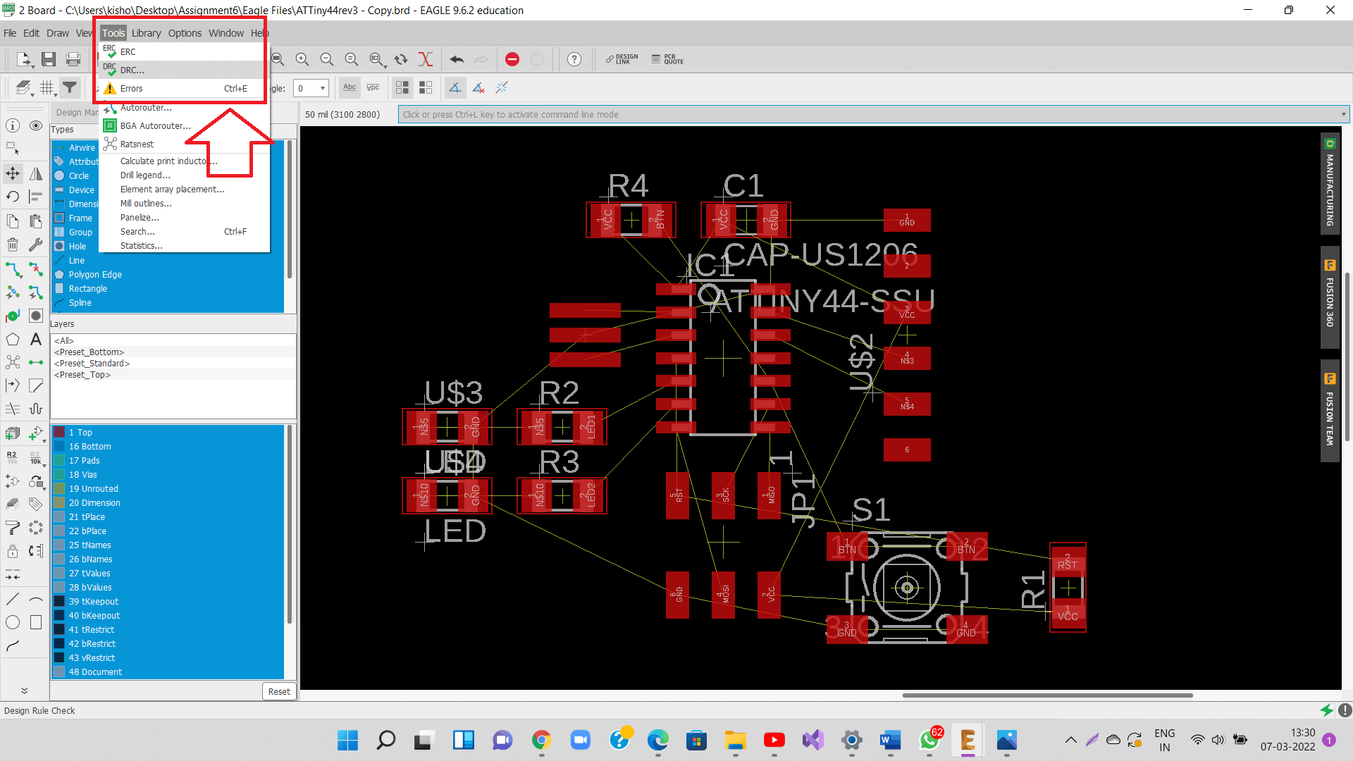
Once all the connections are made in the schematic as per the board, we need to do ERC (Electrical Rule Check) to check if all the nets are properly connected and labeled, do we have any conflicting outputs/inputs and if there are any open or overlapping pins and ports on our schematic.
After we resolve the ERC errors, we approve the schematic for further processing (creating a board).
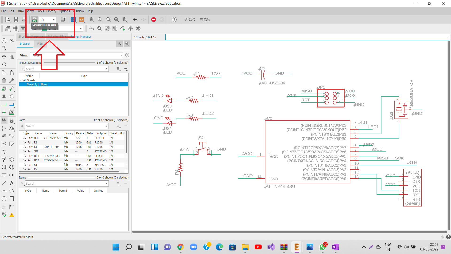
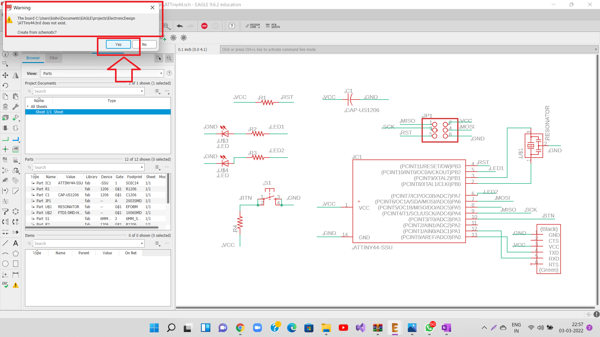
Go to Generate/switch to board on the top left. It will mention in the board does not exist and it can create one for the same as shown in the images below.
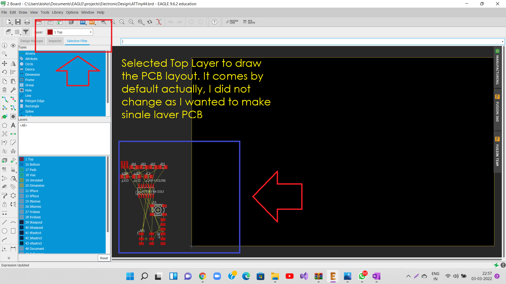
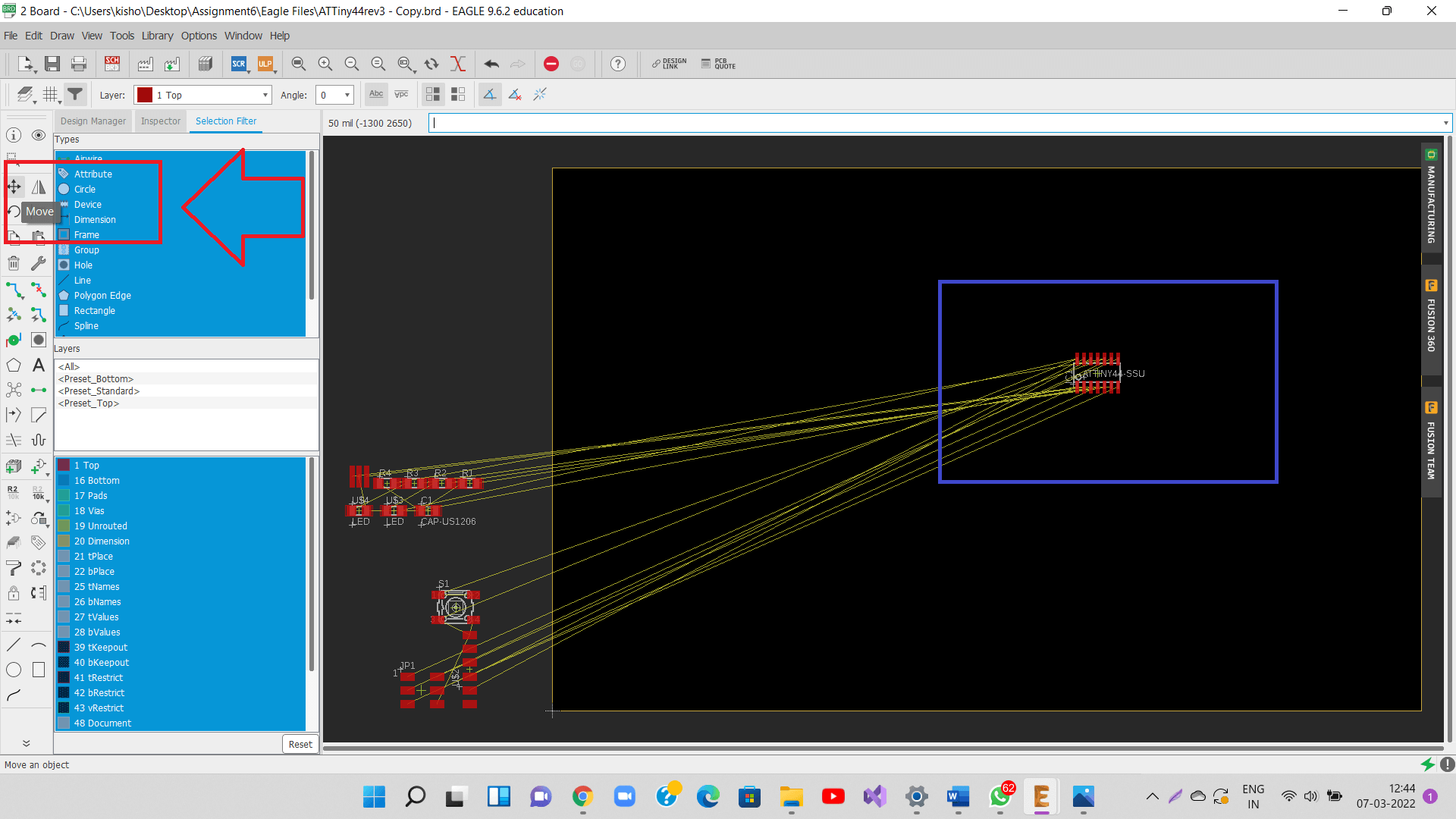
Once inside the board, we will see all the components at the bottom left corner along with their nets. It will select top layer by default. I wanted to design my layout on the top layer only as it was a single layer PCB, so I did not change it.
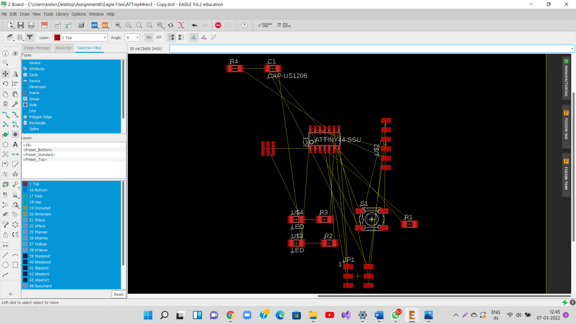
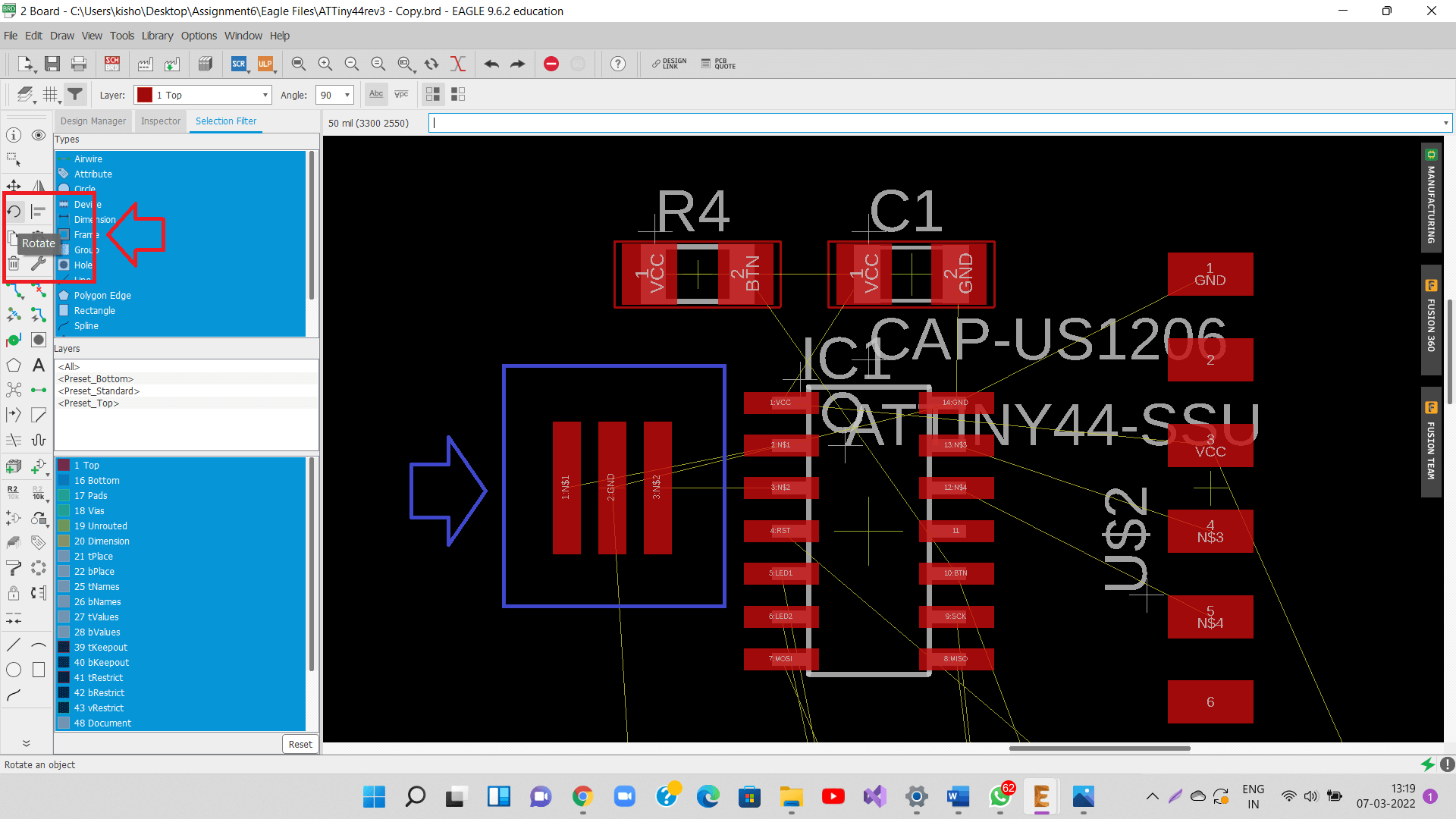
I then used move command to move the components one by one inside the board.
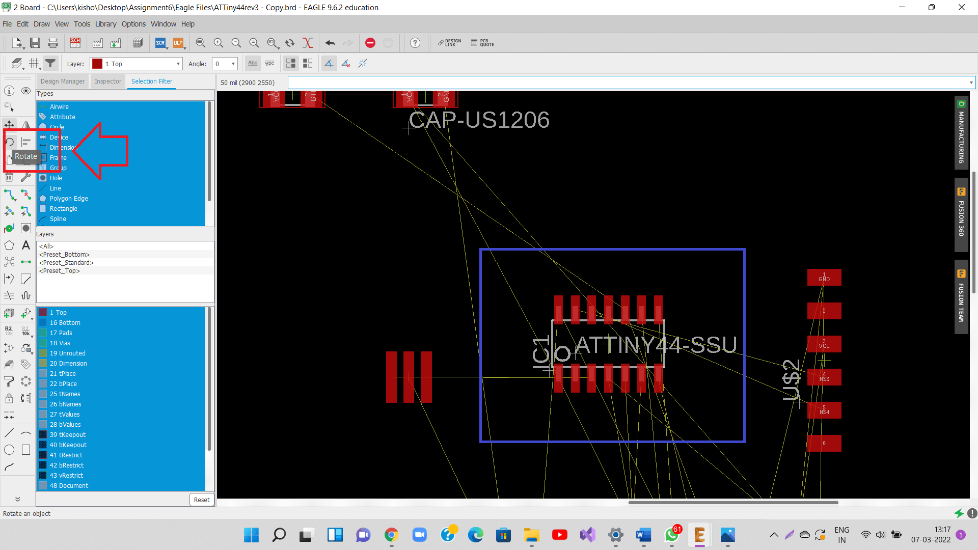
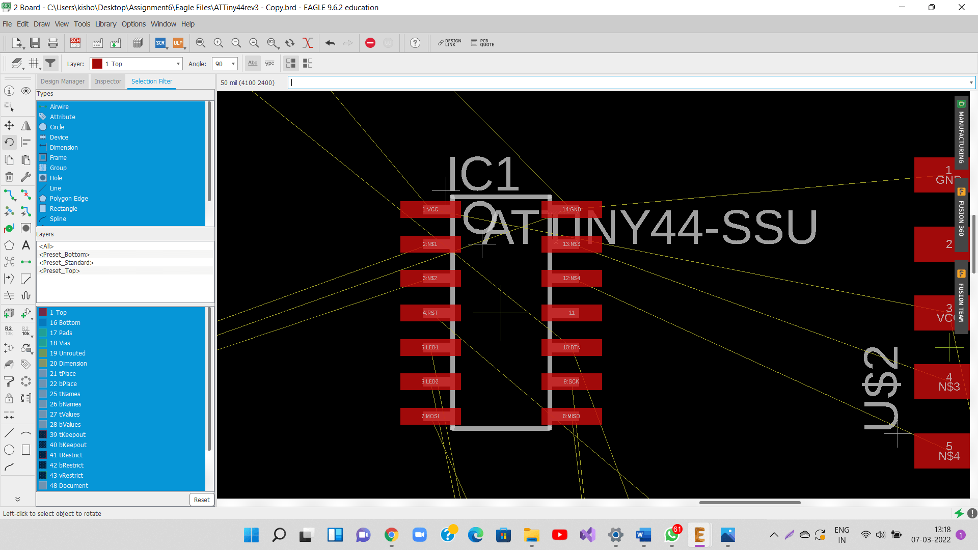
Once all the components were in, I used rotate command to rotate the components as per the requirements. Here, I rotated the ATTiny44 chip.
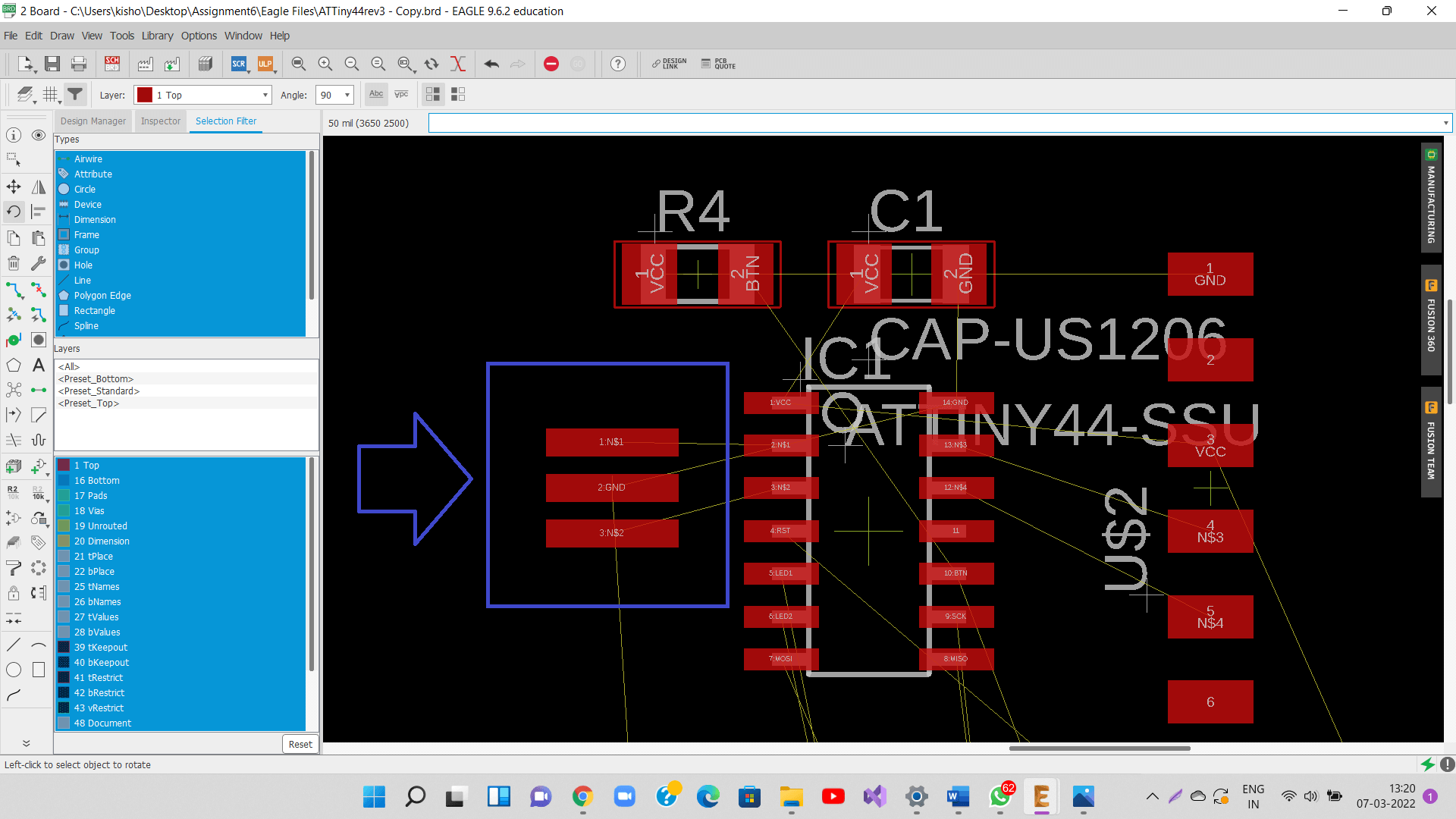
Next, I used rotate command to rotate the resonator as shown below.
Again, I used rotate command to rotate the programming pin header.
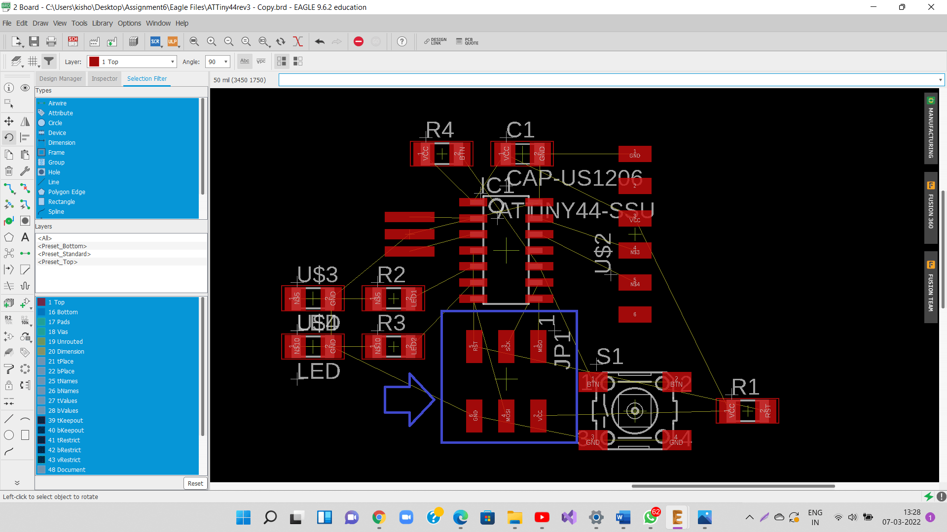
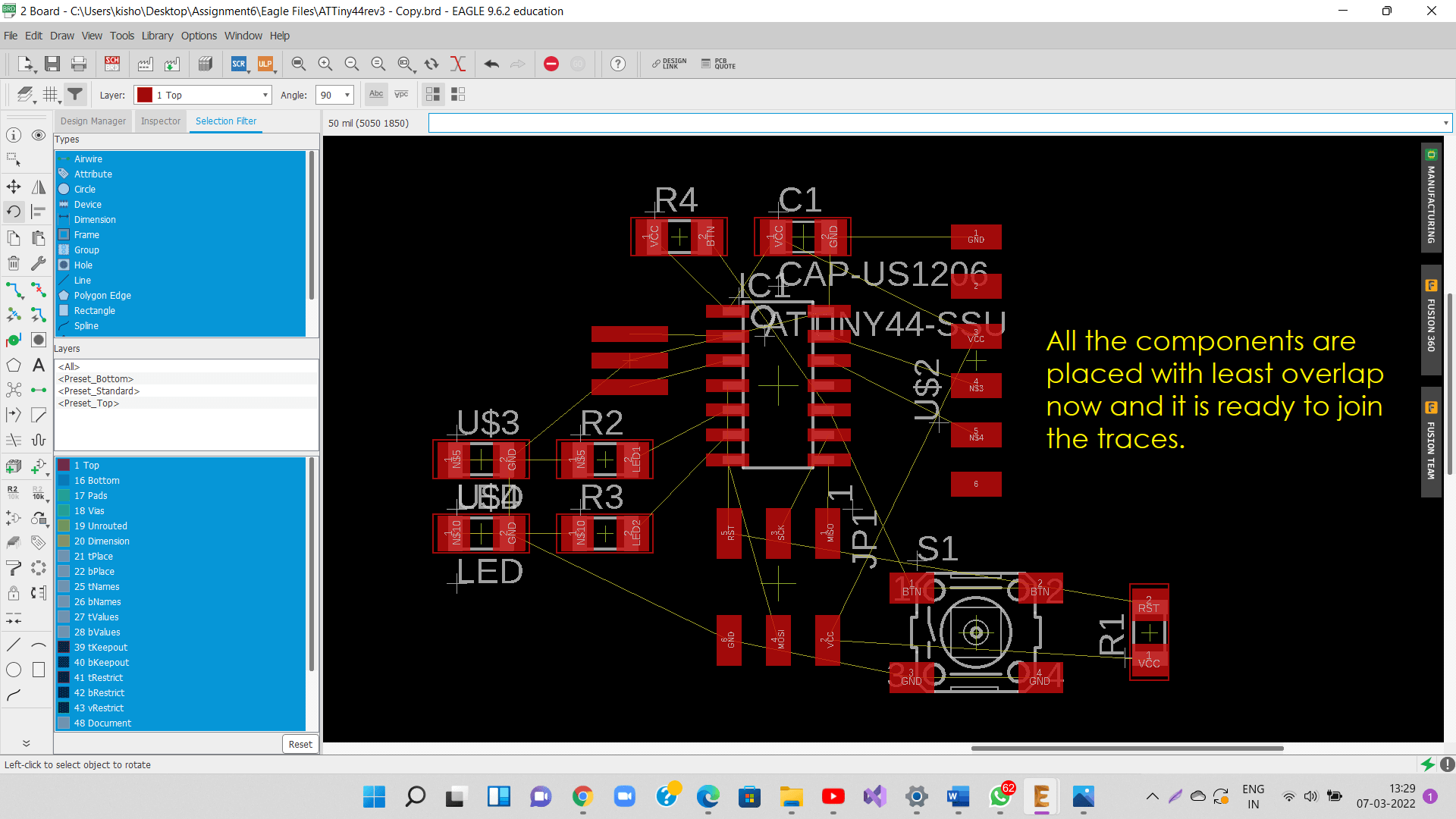
Continued to use move and rotate command on components one by one as per need to get the least overlap of nets in the schematic, so that I can create routing without overlaps.
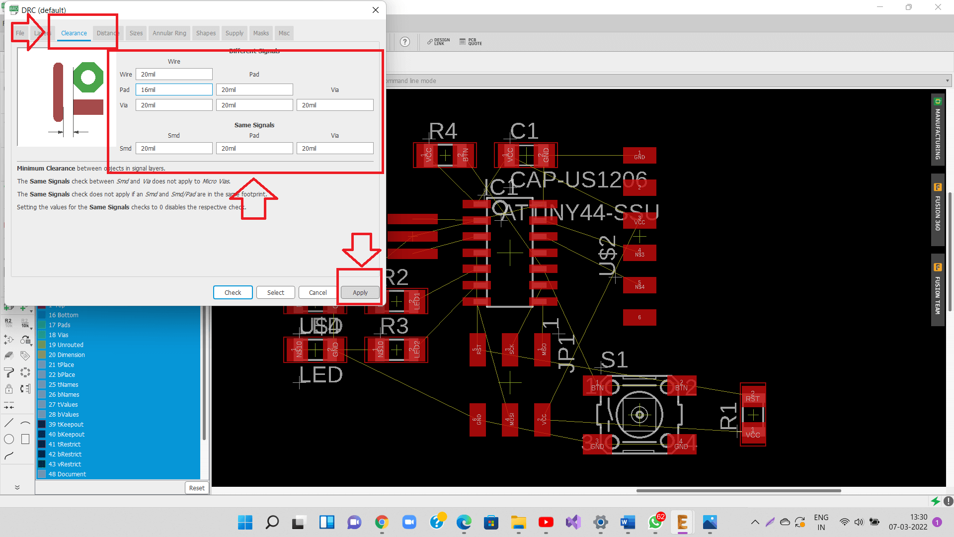
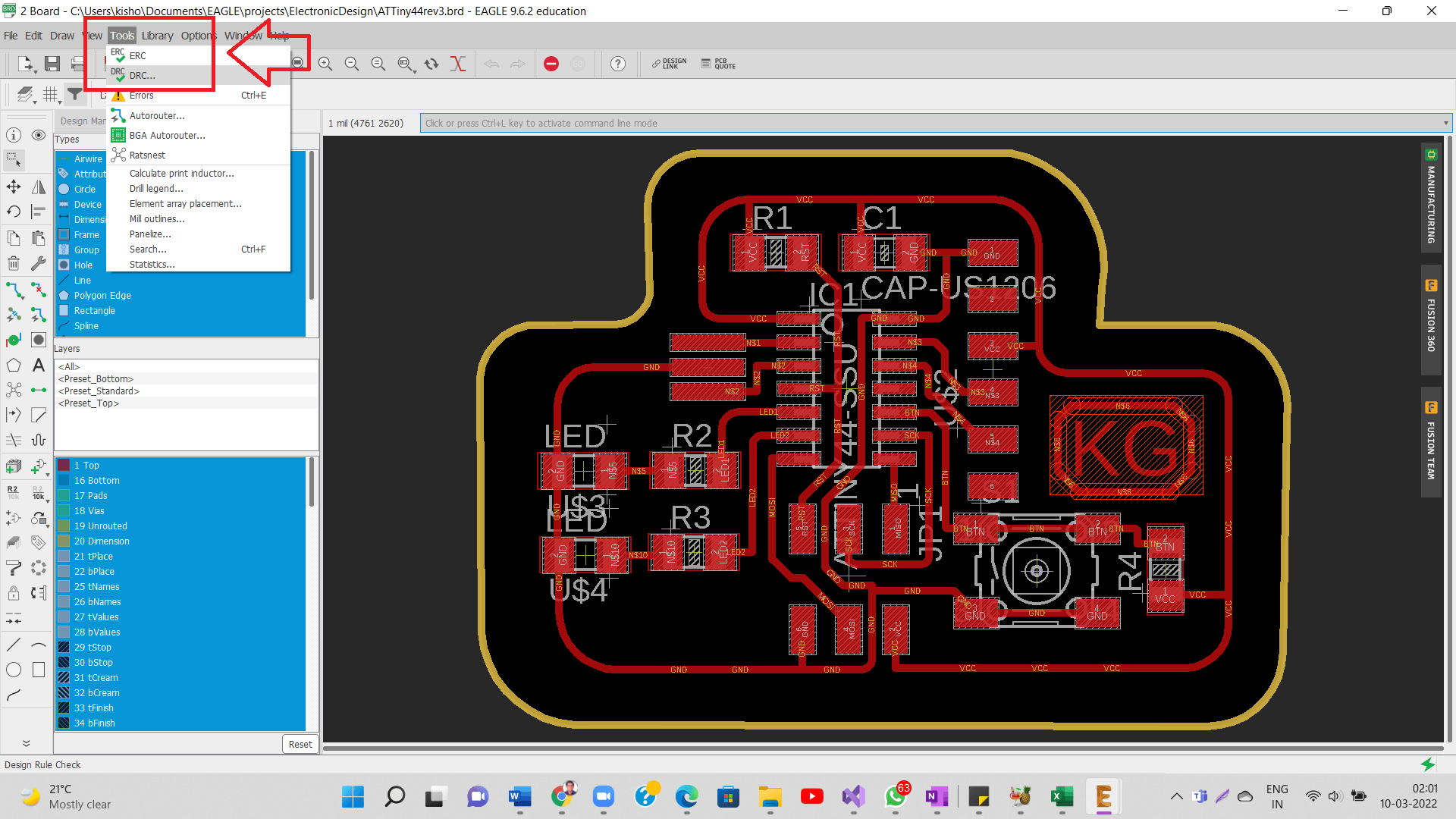
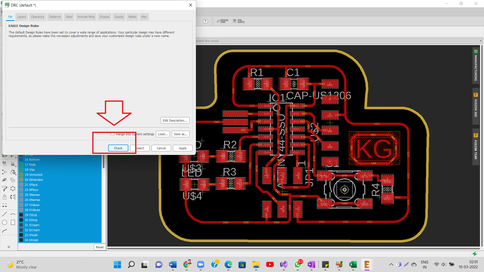
Before I started routing (create traces), I need to set up some parameters like size of the traces, minimum gap between trace padding. as per the DRC (Design Rule check)
I kept a distance of 20 mils between traces and 16 mils between traces and pads. 1 mil = 0.0254 mm.
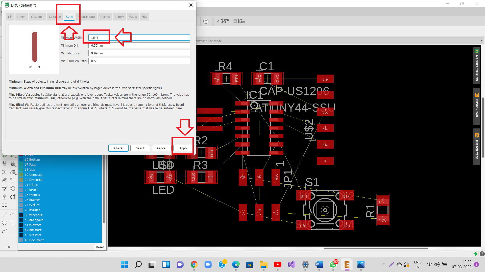
I kept trace wideth of 16 mils (0.016 inch) as my end mill diameter is 0.0154 inch. 1 mil = 0.001 inch
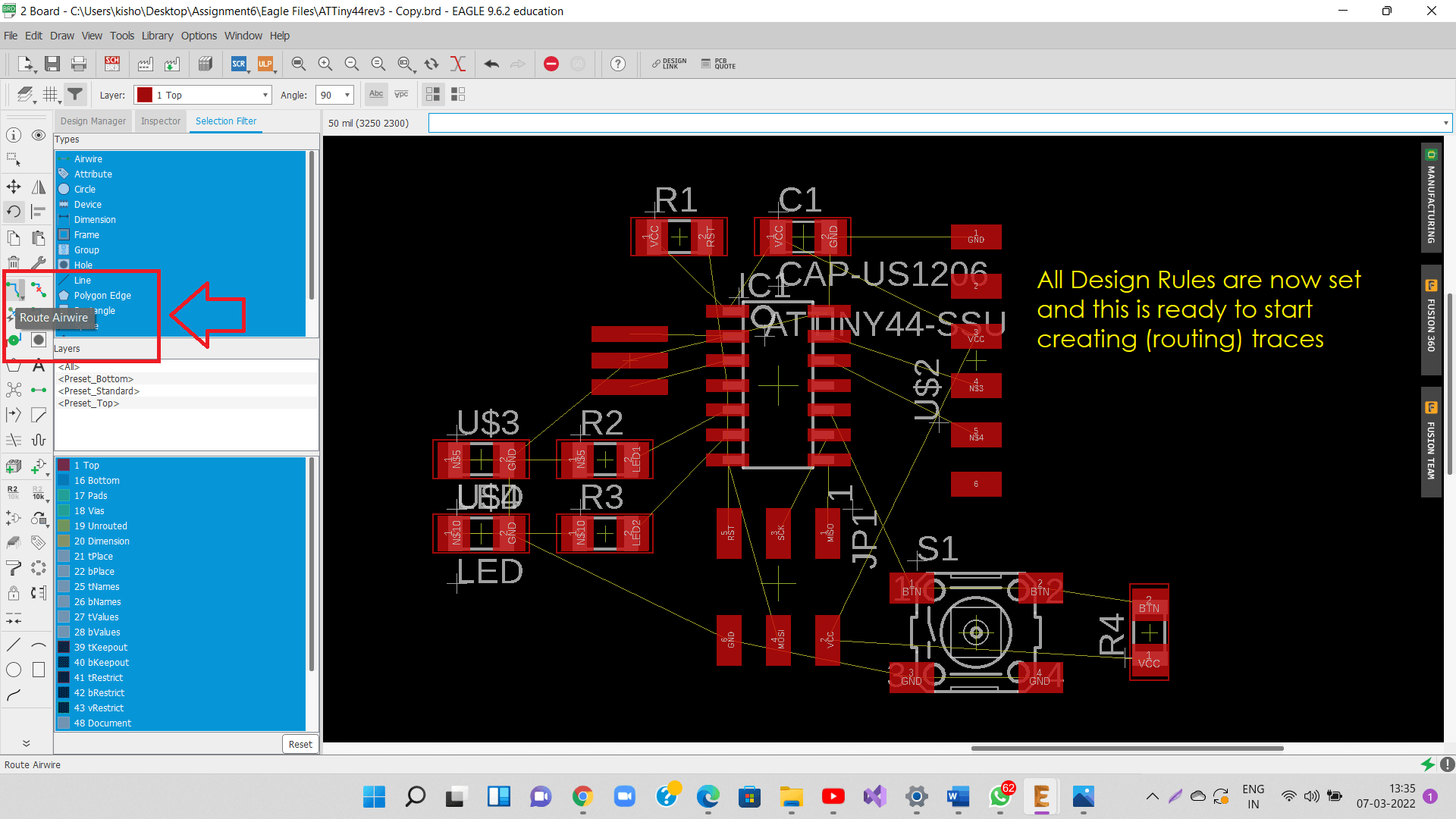
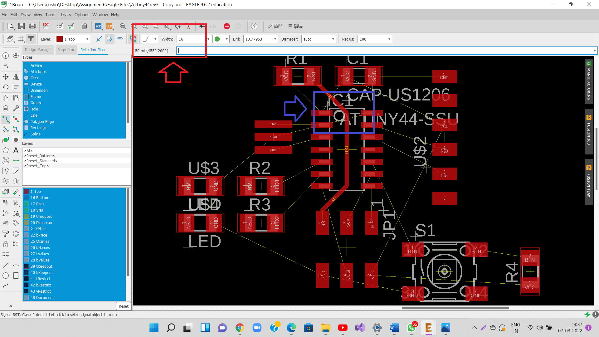
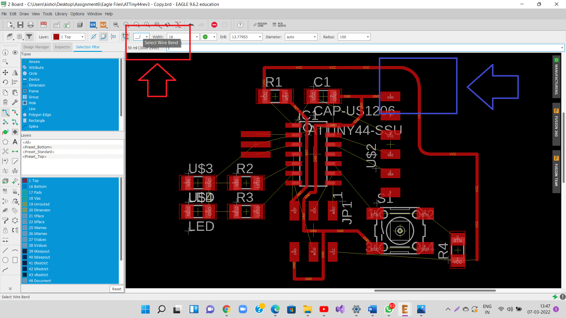
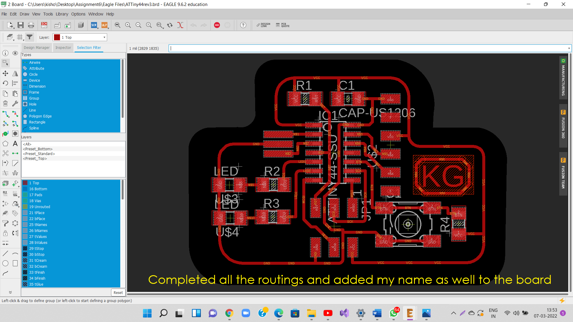
After all design rules are set, we can start routing (creating traces) as shown below.
I avoided sharp corners (sharp change in trace direction), as shown below. 90 deg turn in a trace will result in charge losses.
Similarly, I also used rounded corners for both aesthetic and loss avoidance reasons.
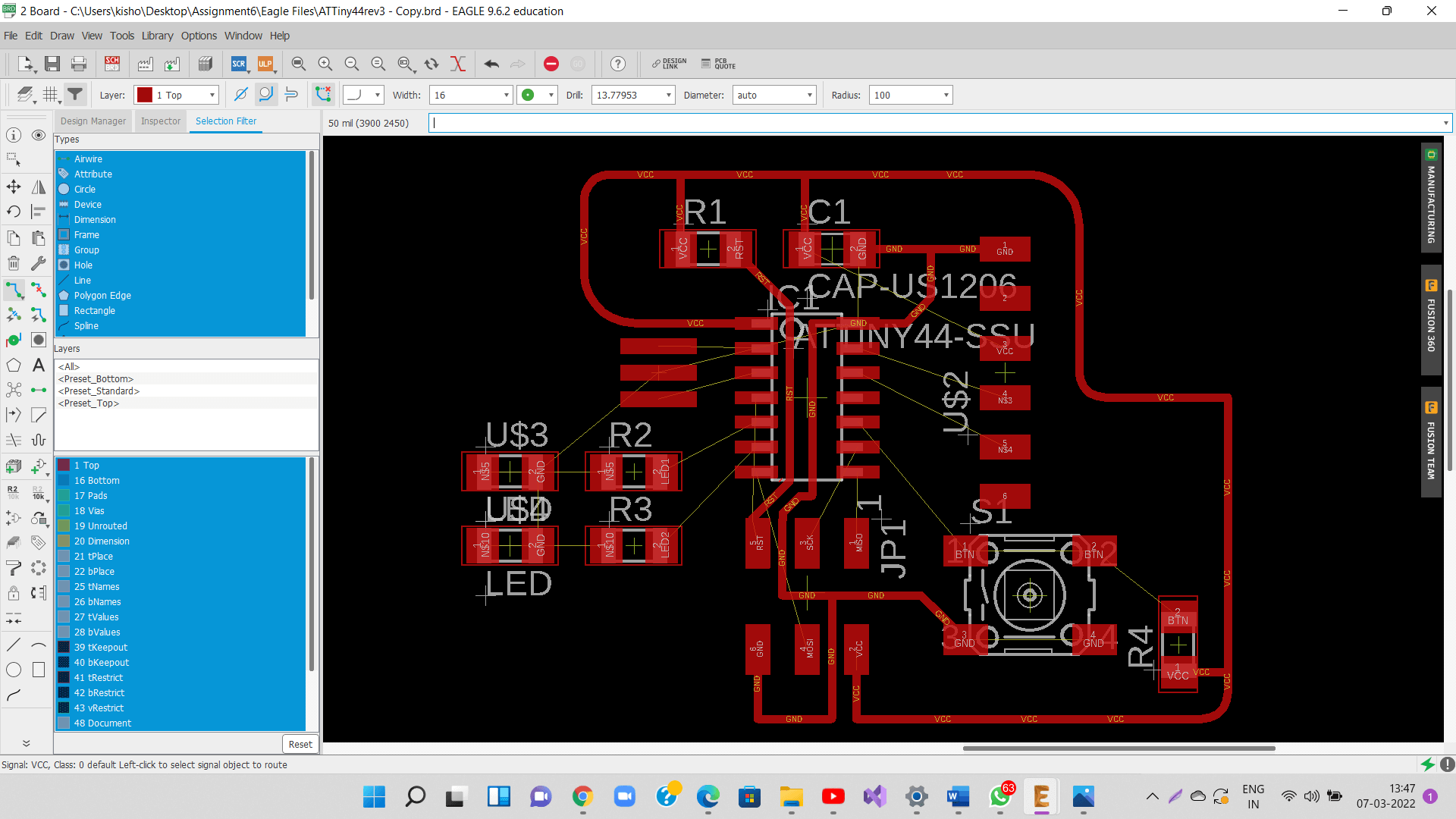
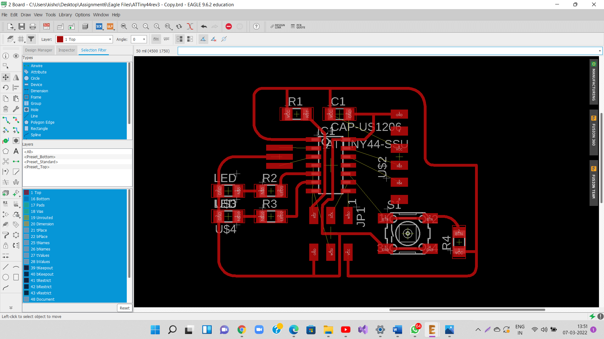
I needed to relocate the components by move command, rotate them again while creating routing so as to eliminate routing crossings totally.
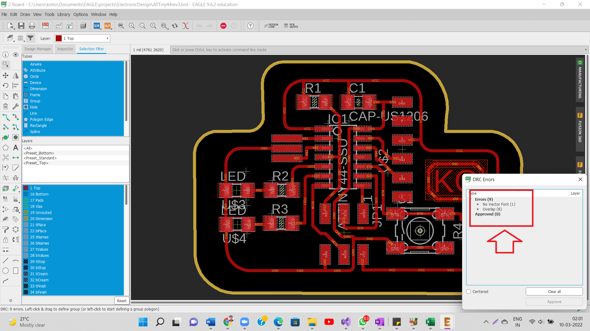
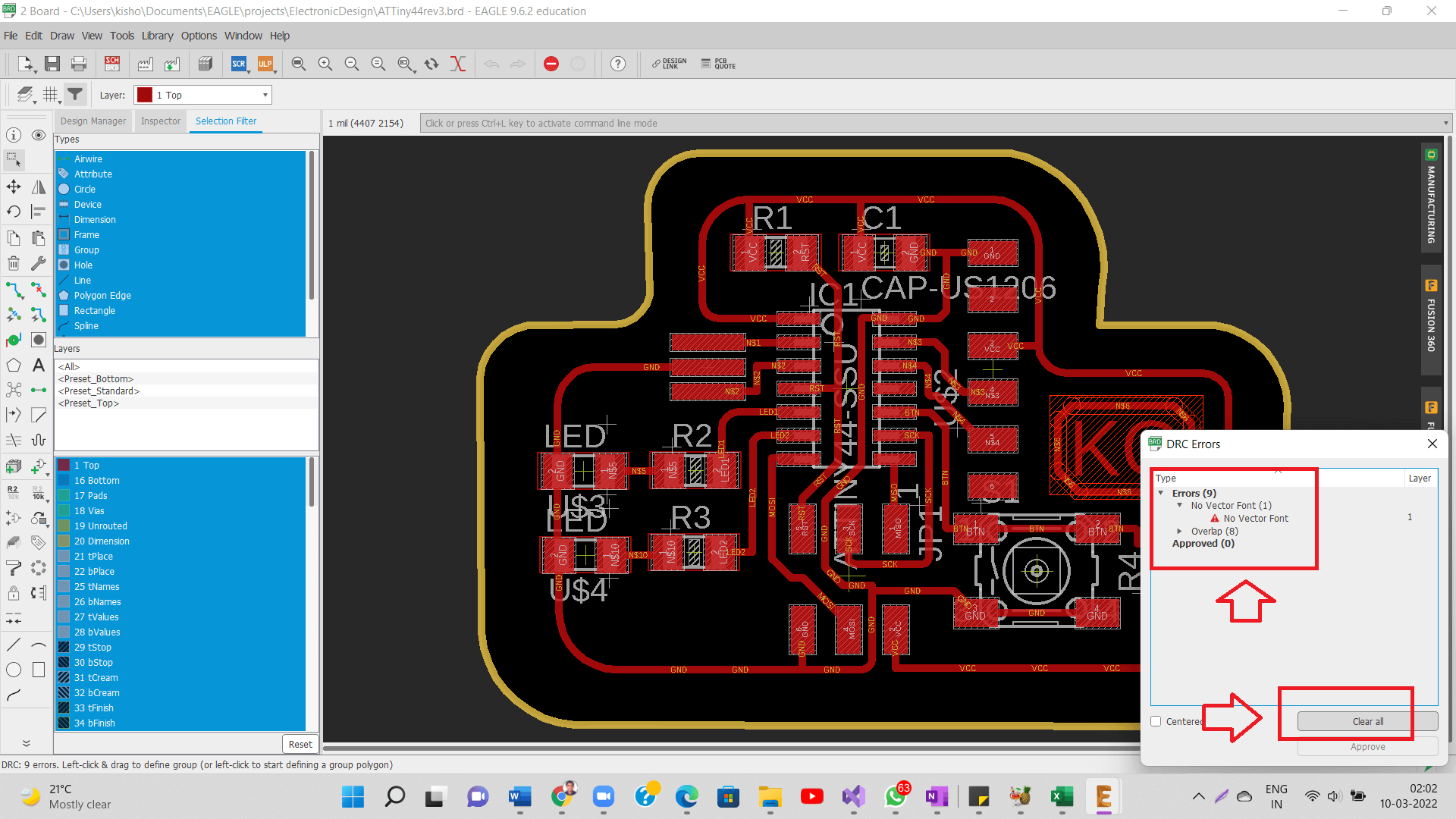
Once all the routings were done, I did run DRC again to check if there are design rules errors.
Only upon resolving all the DRC errors, I can confirm this as my final design. Eagle will also highlight areas in the design, where there are any traces, pads not following the Design rules. These design rules are set-up as per the end mill diameter (Remember assignment on electronic production?). Tool path for milling the PCB will not be generated if the design does not follow the DRC.
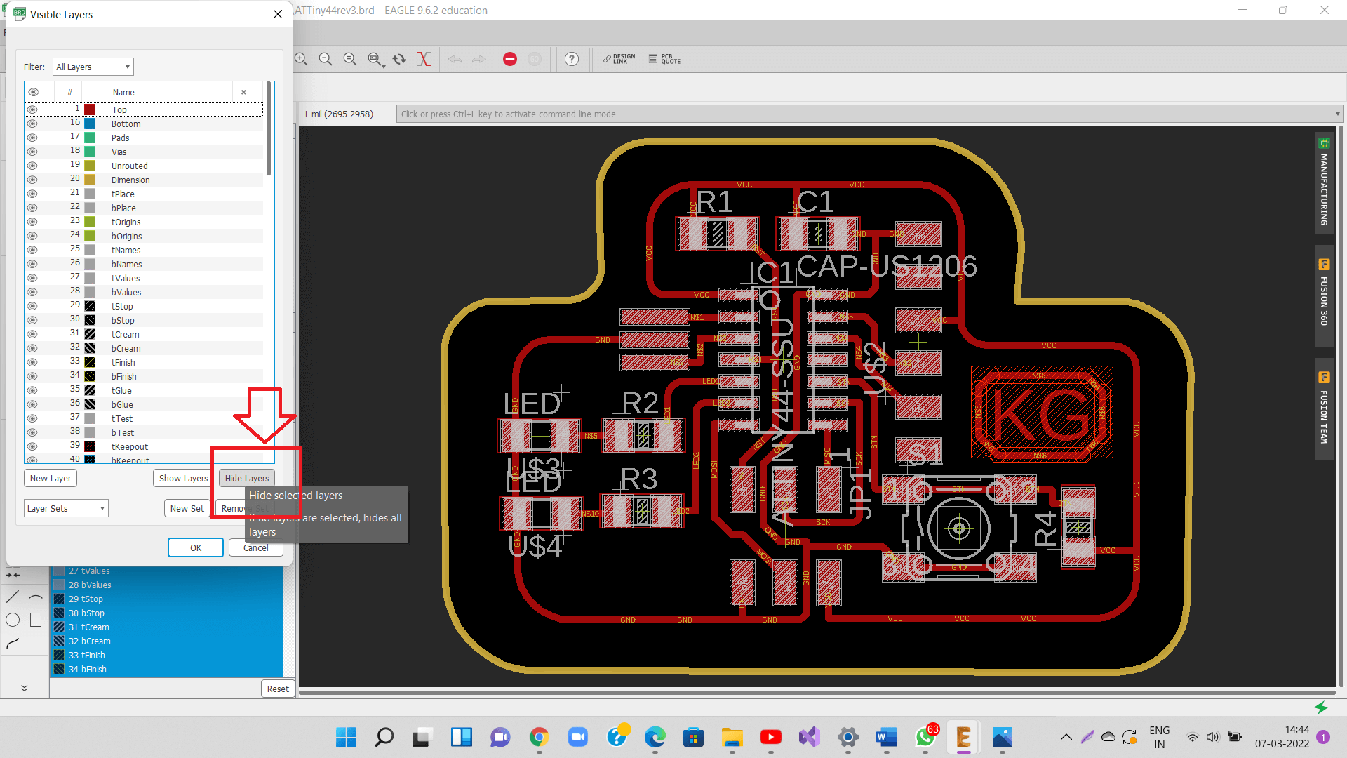
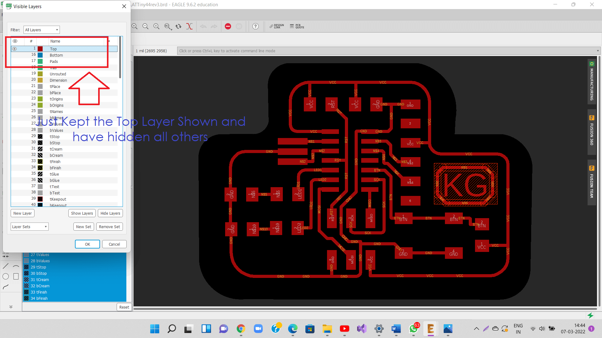
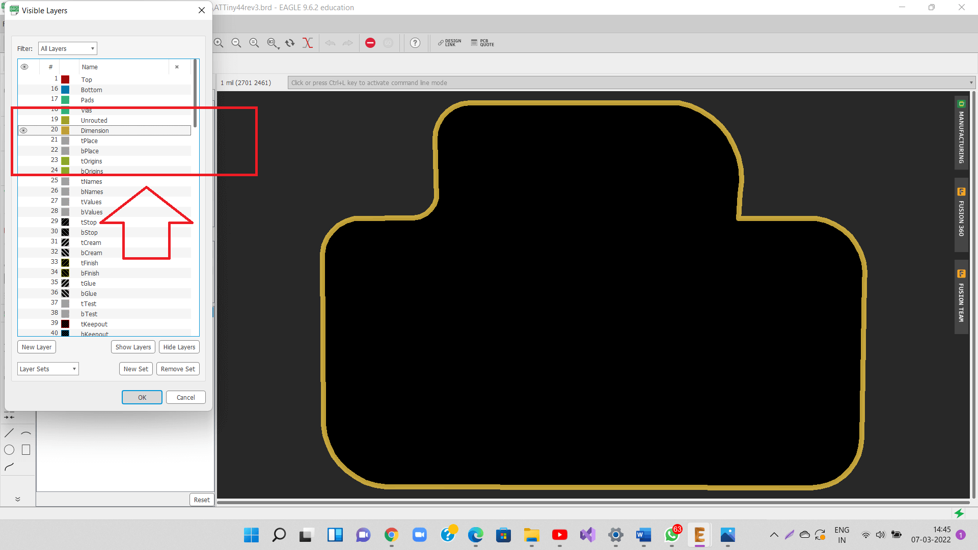
Now, go to layers, select all layers and say Hide all layers and Turn On only the top layer as shown in the two images below.
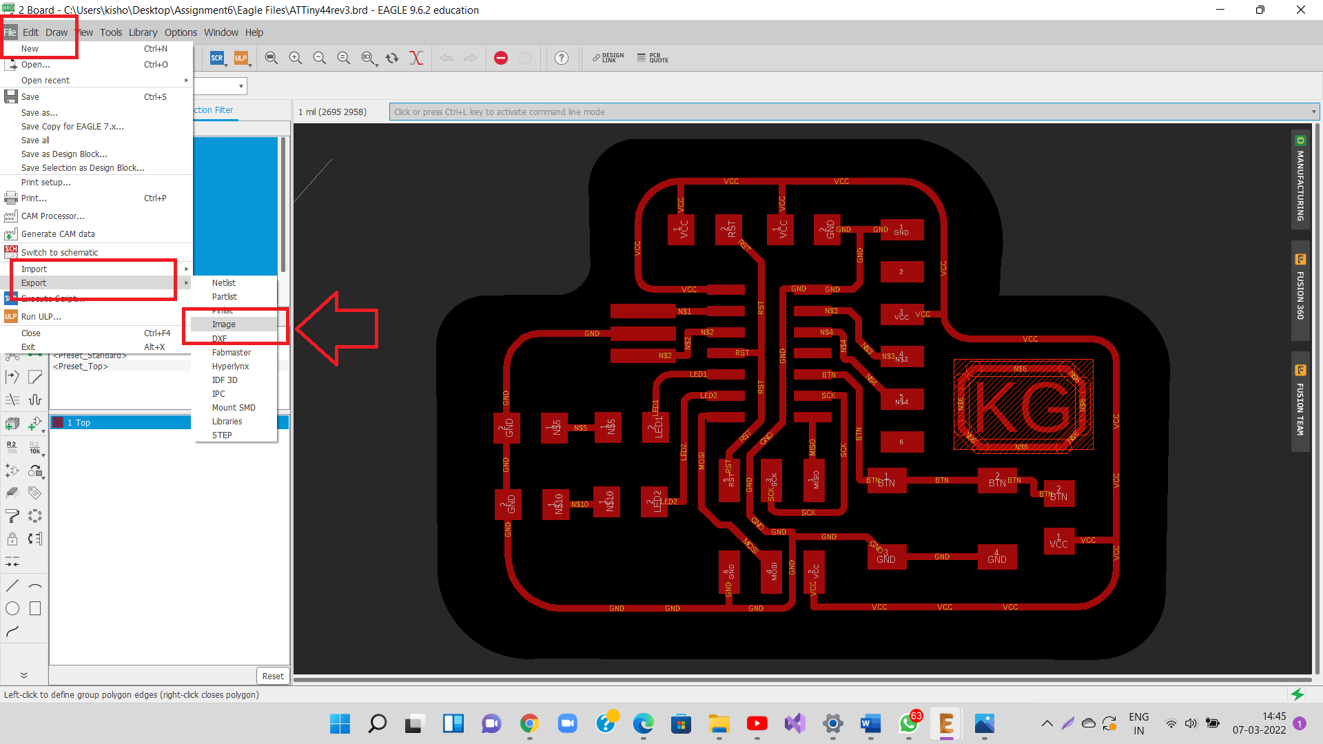
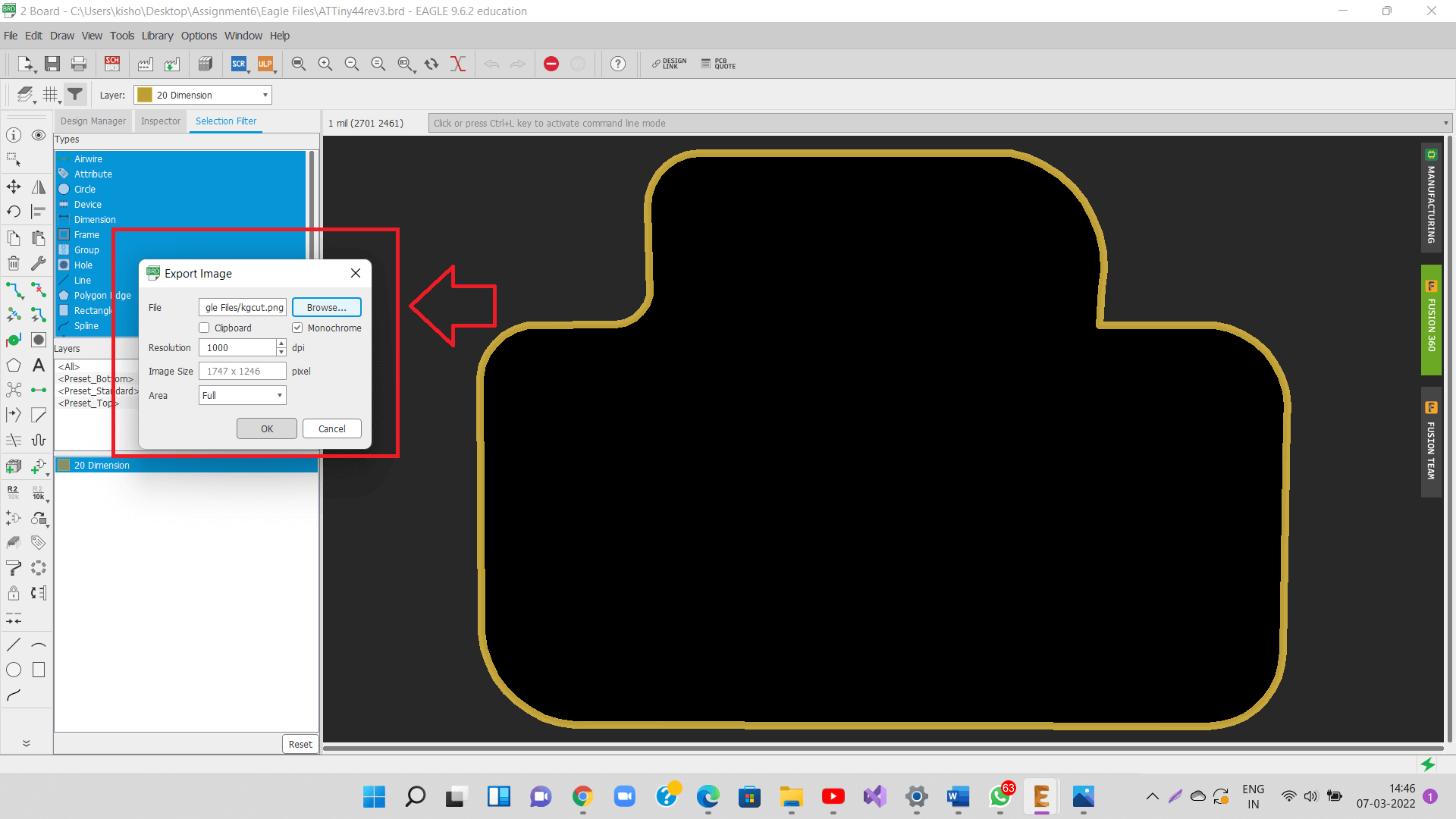
Next, to export the PCB layout as PNG file for milling, go to File- Export- Image menu.
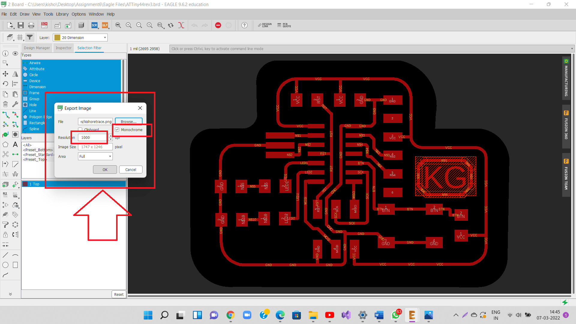
Check monochrome option and 1000 dpi, and browse the location, where the png file will be exported to and export the PNG file for tracing.
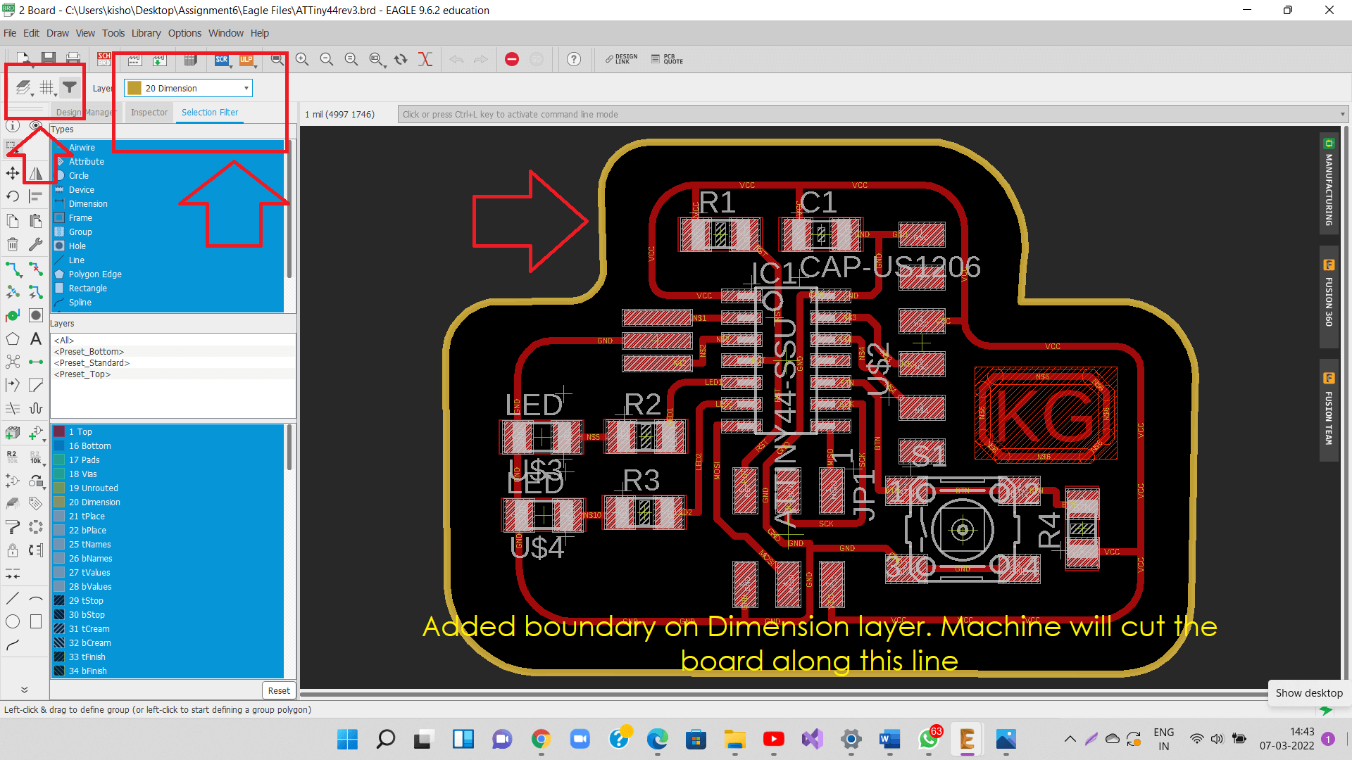
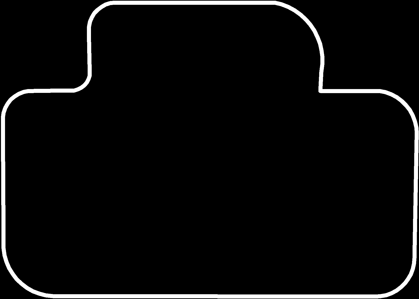
Now hide top layer and show dimension layer, on which the cutting border has been drawn to generate its png file for cutting.
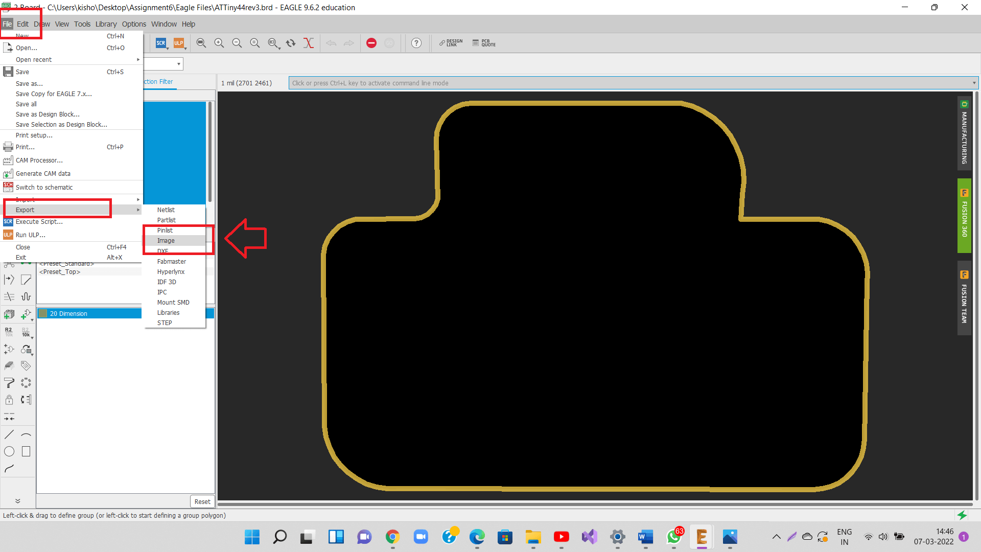
Follow same steps now to export the PNG file for cutting.
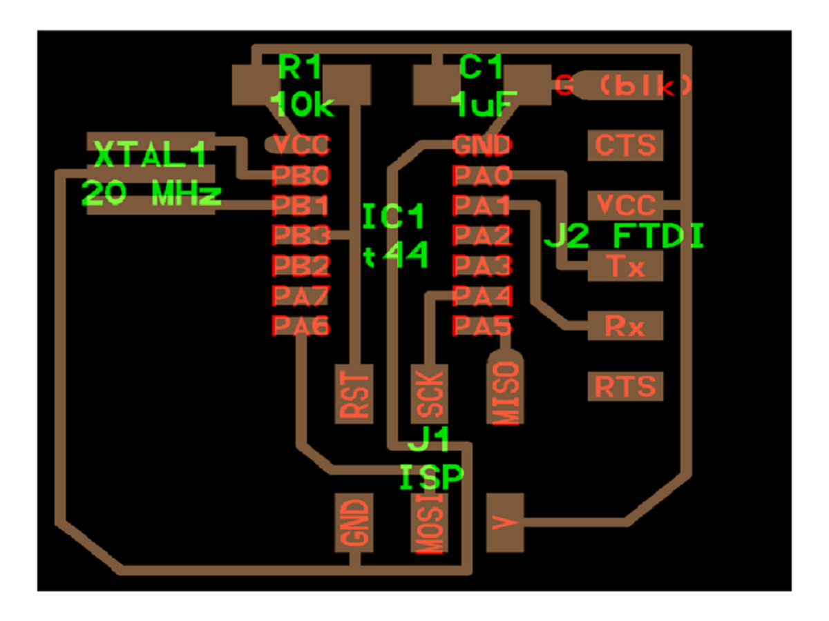
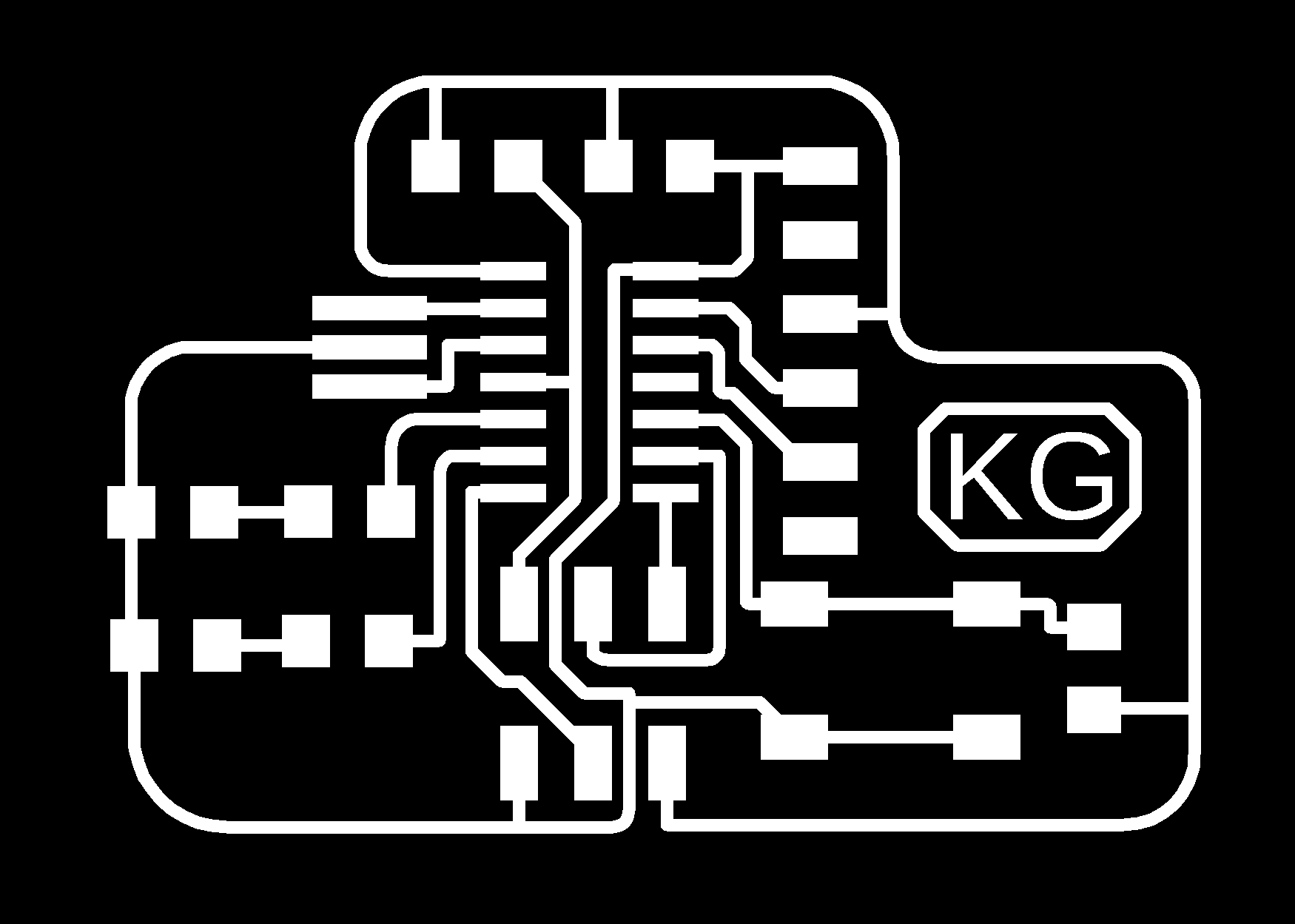
Below is my PNG file for tracing.
And this one is PNG file for cutting. Finally, that completes the task of PCB layout designing, congratulations to me :-)
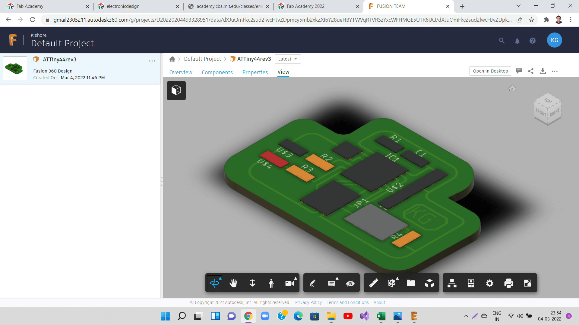
I also tried to generate a 3D model of my PCB in Fusion 360 option inside Eagle to visualize how my PCB will look like.
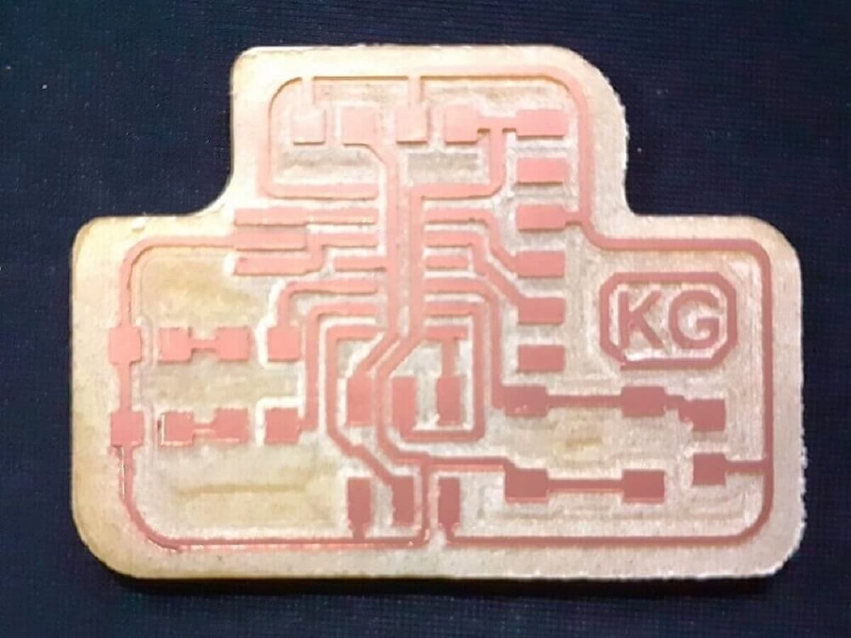
Milling Echo Hello-world Board
Now, I used Roland SRM20 milling machine to mill the traces and cut the PCB.
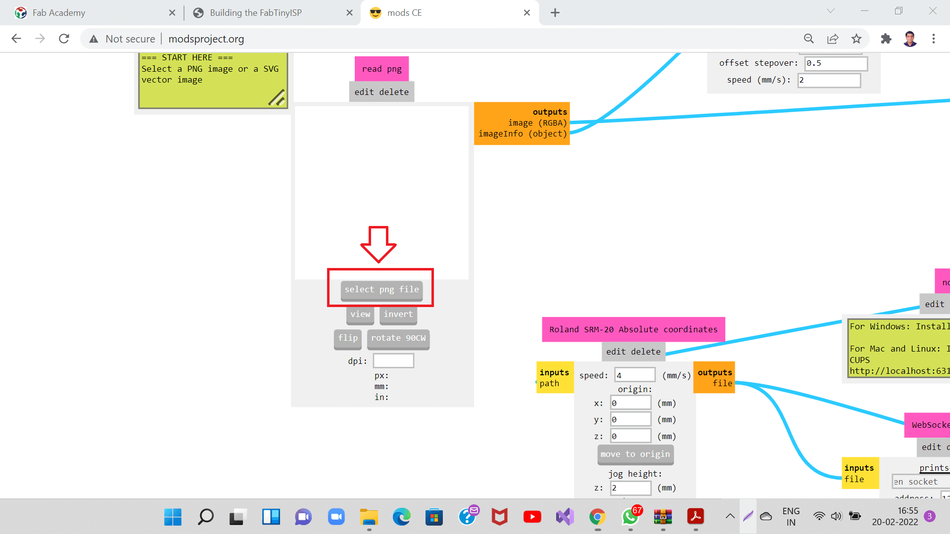
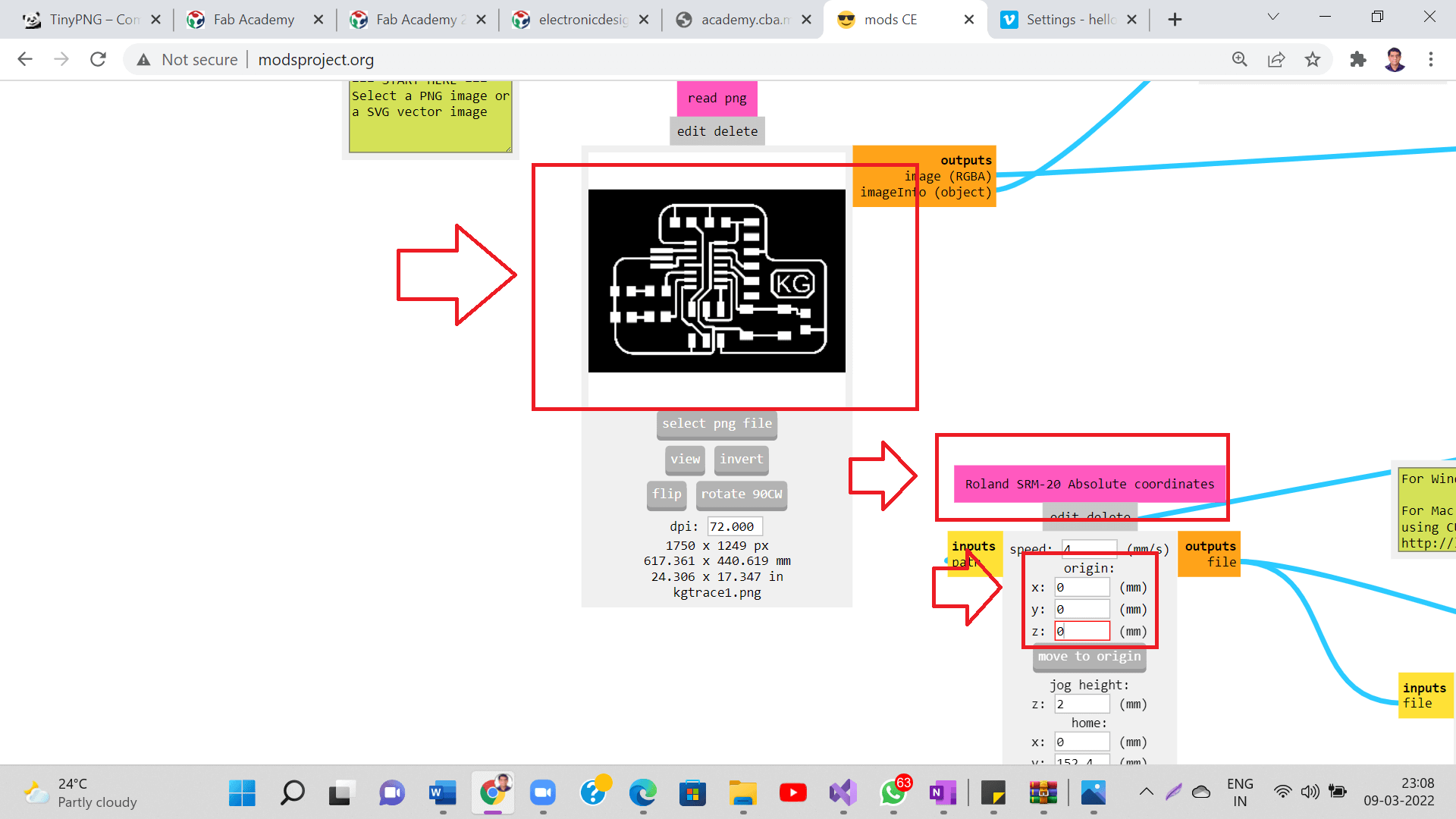
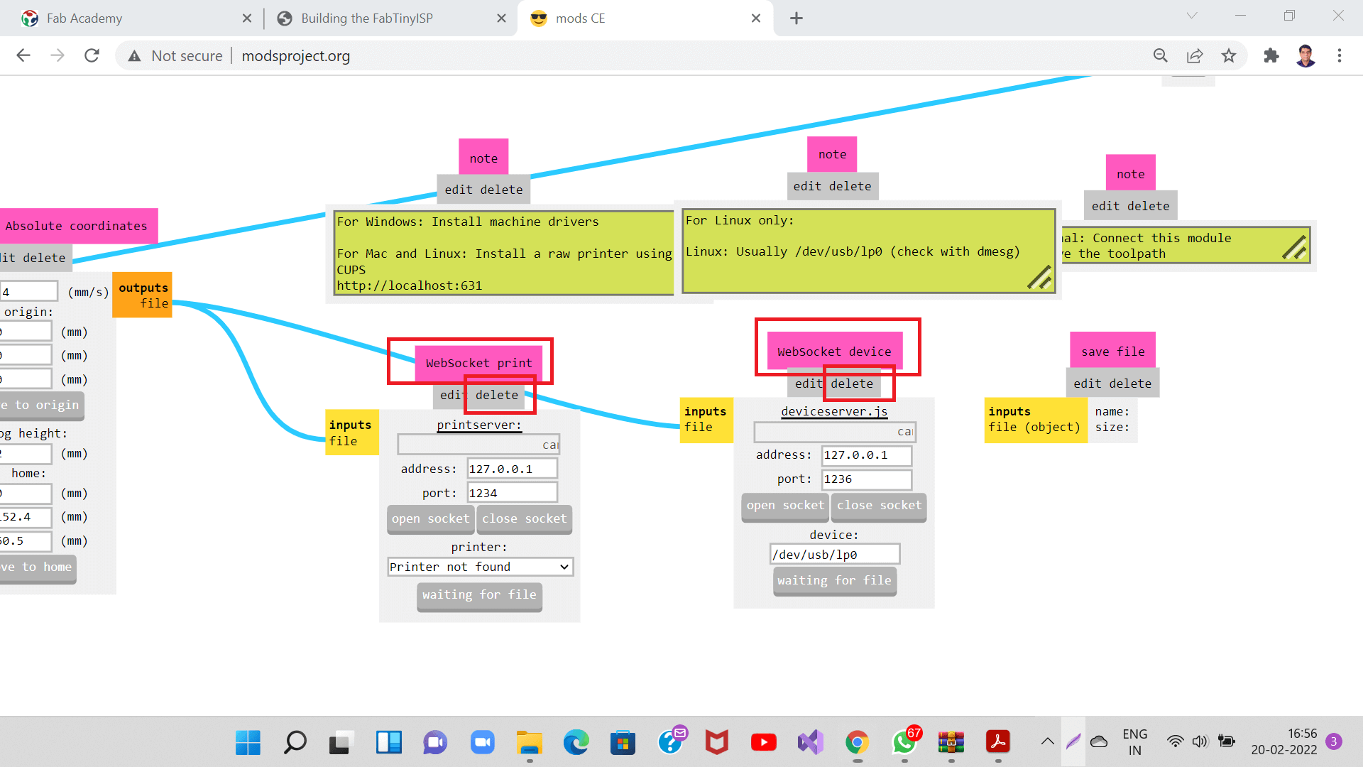
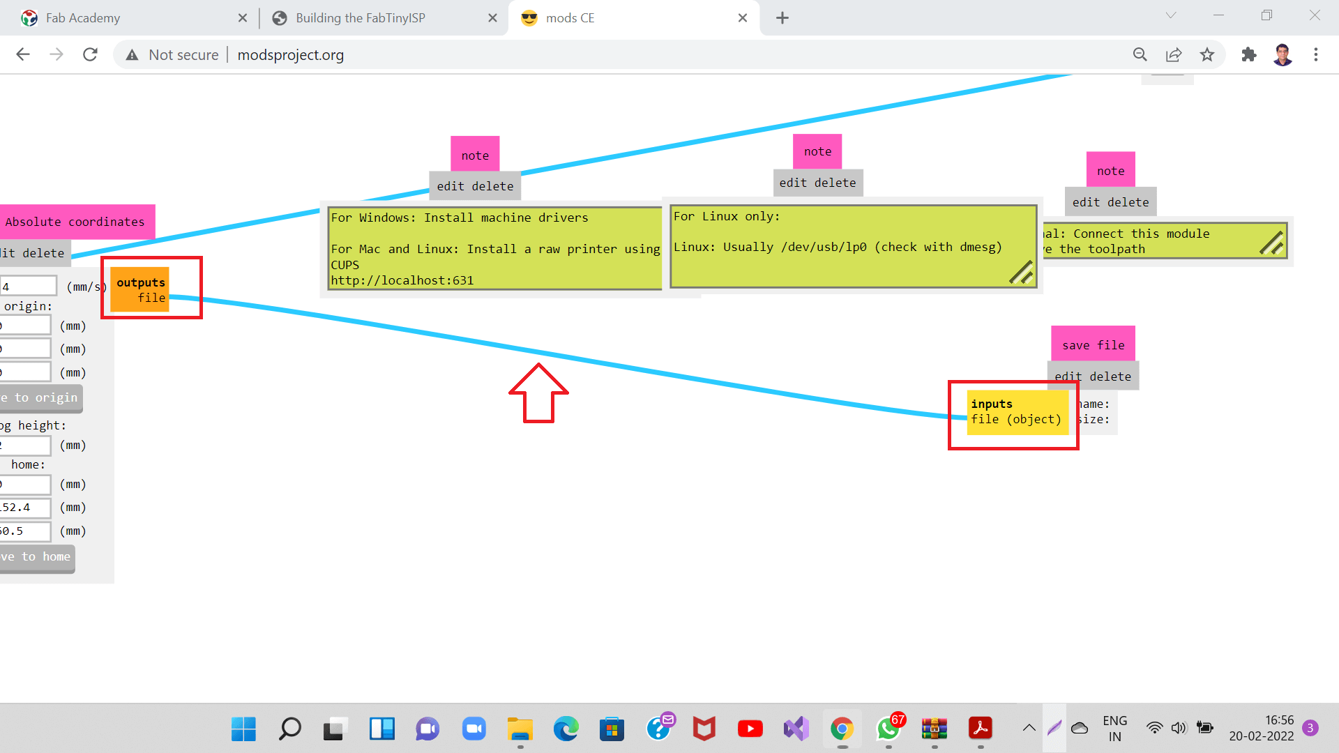
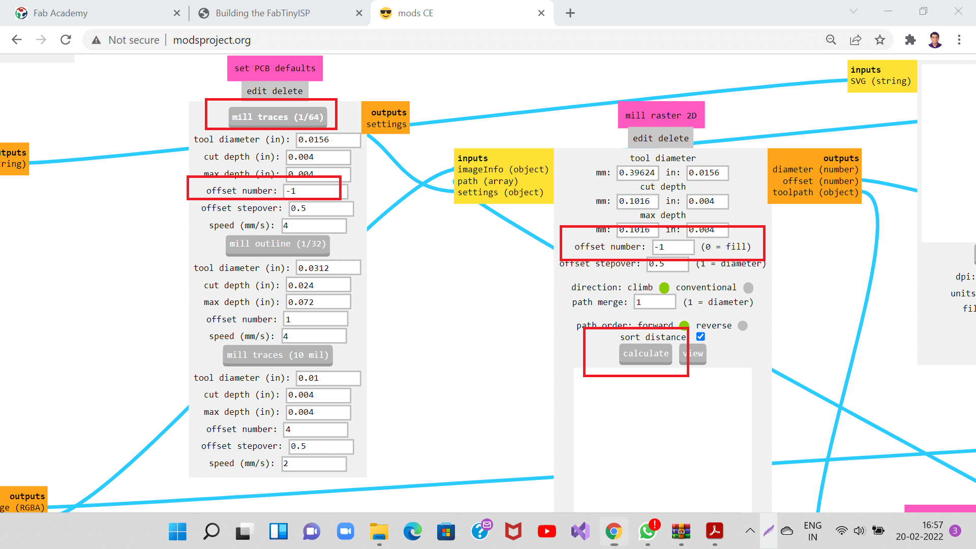
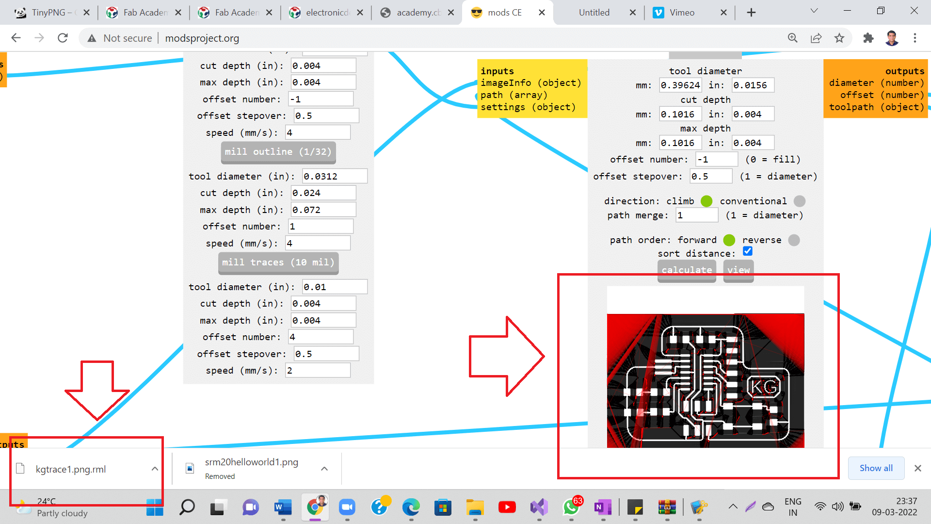
I generated toolpath for tracing and cutting using modsproject like what I did in the week of Electronic Production. Following are the steps I followed. For detail explaination of these steps are given in earlier assignment on electronic production.
Following is a short video I captured while milling the traces.
Here is the PCB of my echo Hello-world Board. Clap Clap.
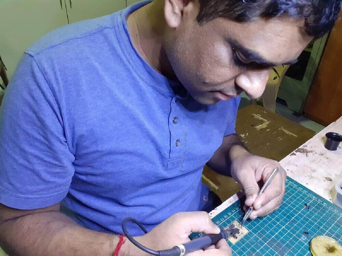
Soldering SMD components on Echo Hello-world Board
I assembled my PCB with components required on my board. This time it took little time to solder as compared to the last time I soldered FabISP board. Yes, I yet need to practise more for soldering tiny pins of the microprocessors and also to solder on the close-by traces.
How did I calculate the value of Resistor for LED?
I used Ohms law to find out the value of the resistor required for two of the LEDs. I refered to the Datasheet of the LEDs and found out that V = Input voltage - LEDs forward voltage (from datasheet ) = 5V - 2V = 3V. Next parameter required is I = forward current (from datasheet) = 30mA. So, the resistor value is, R=V/I, R=3V/30mA= 3V/0.03A= 100 ohm. So, I used 100 ohm resistor one each for my LEDs on the board.
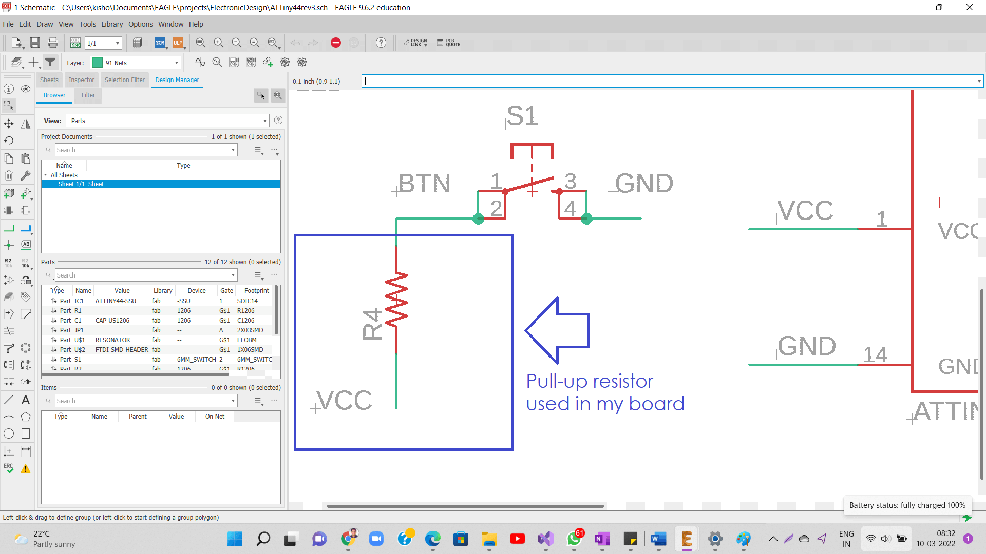
Why did I use Pull-up resistor for my push button?
Pull-up resistors are very common when using microcontrollers (MCUs) or any digital logic device. Let's say you have an MCU with one pin configured as an input. If there is nothing connected to the pin and your program reads the state of the pin, will it be high (pulled to VCC) or low (pulled to ground)? It is difficult to tell. This phenomena is referred to as floating. To prevent this unknown state, a pull-up or pull-down resistor will ensure that the pin is in either a high or low state, while also using a low amount of current. The pull-up resistor is connected to the high voltage (this is usually 3.3V or 5V and is often refereed to as VCC) and the pull-down resistor is connected to ground. Pull-ups are often used with buttons and switches.
With a pull-up resistor, the input pin will read a high state when the button is not pressed. In other words, a small amount of current is flowing between VCC and the input pin (not to ground), thus the input pin reads close to VCC. When the button is pressed, it connects the input pin directly to ground. The current flows through the resistor to ground, thus the input pin reads a low state. Keep in mind, if the resistor wasn not there, your button would connect VCC to ground, which is very bad and is also known as a short.
How did I calculate the value of Pull-up Resistor for button?
Again, I used Ohms law to find out the value of the pull-up resistor required for the button. V = 3V. Next parameter required is I = current value I want to limit to is = 30mA. So, the resistor value is, R=V/I, R=3V/30mA= 3V/0.03A= 100 ohm. So, I used 100 ohm pull-up resistor for the button on the board.
Programing my Echo Hello-world Board
The next interesting part is programming for hello-world board. I need two things, a programmer (I used my FabISP board, which I designed in the week of electronics production) to program by echo hello-world board and second thing is Arduino IDE, where I can compile and upload different programs to my board. Following are the steps I followed for programming:
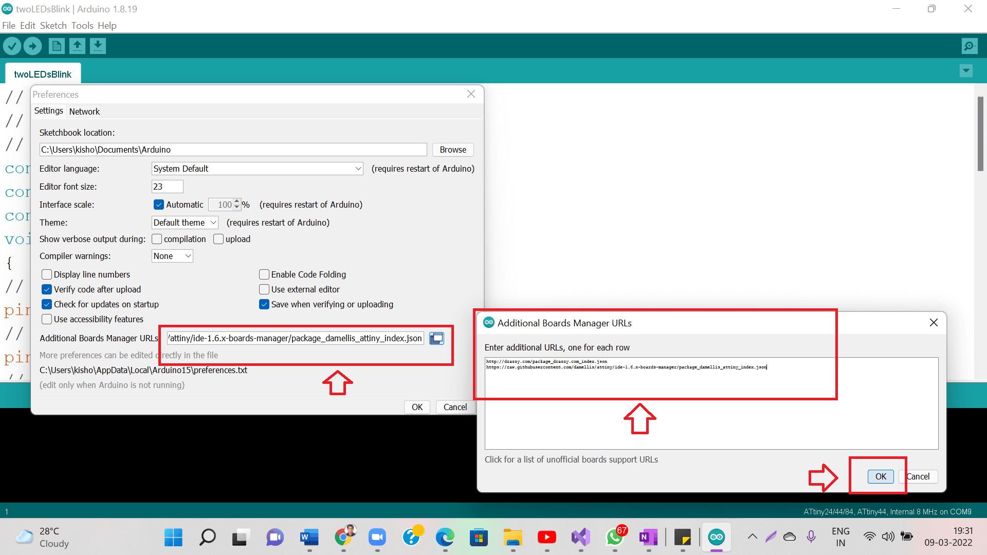
Step1: Open Arduino IDE, go to File- Preferences.
Click on the button in Additional boards manager (highlighted below), a small window will open, add this URL link there to be able to add additional boards (in our case ATtiny44) in Arduino IDE https://raw.githubusercontent.com/damellis/attiny/ide-1.6.x-boards-manager/package_damellis_attiny_index.json
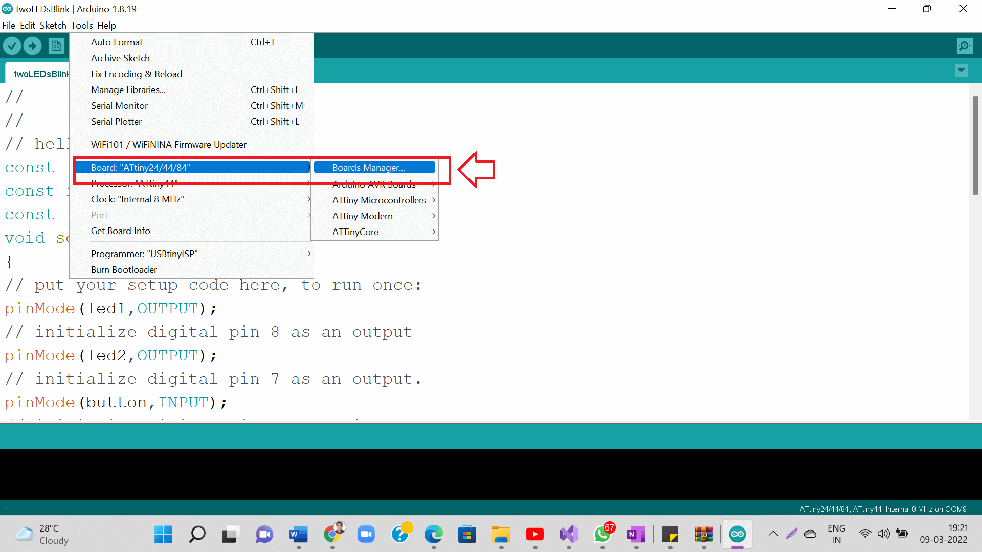
After above step, go back to the Arduino IDE main screen, go to Tools- Boards- Boards Manager as shown below.
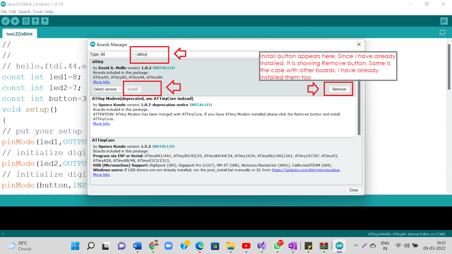
Search attiny and install this board as shown below.
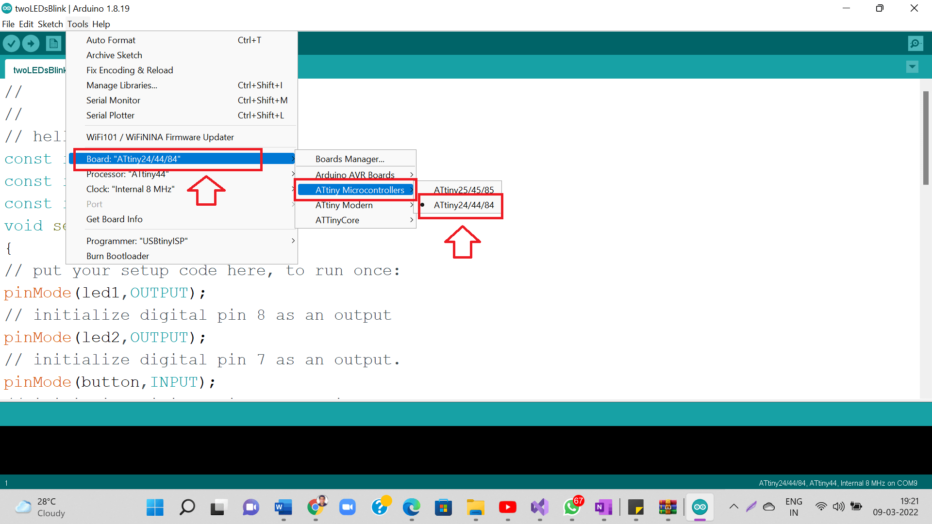
Once installed these boards, again go back to Tools- Boards Select ATtiny Microcontrollers and then select ATtiny24/44/84 as your board as shown below.
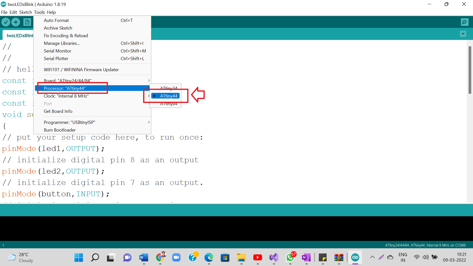
Select ATtiny44 as your Processor as shown below.
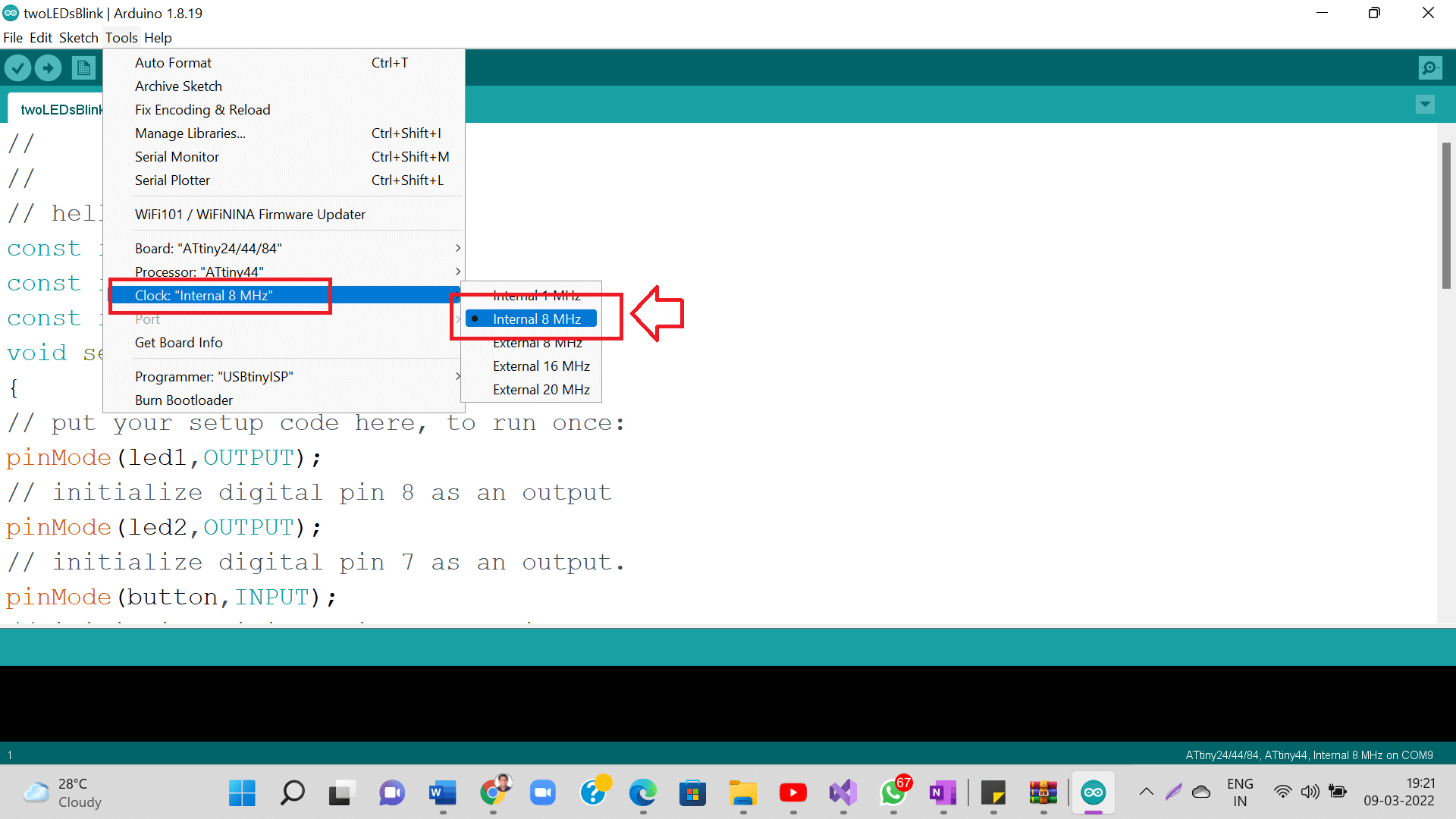
Set internal clock 8 MHz as shown below.
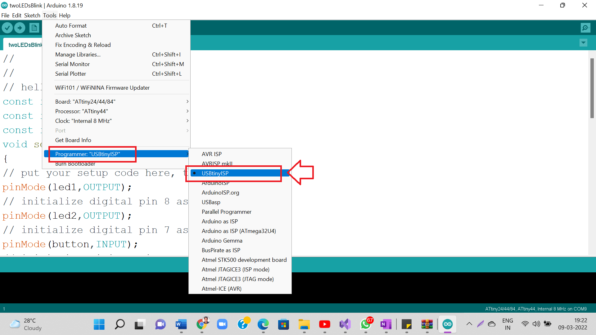
Select USBtinyISP as your Programmer as shown below.
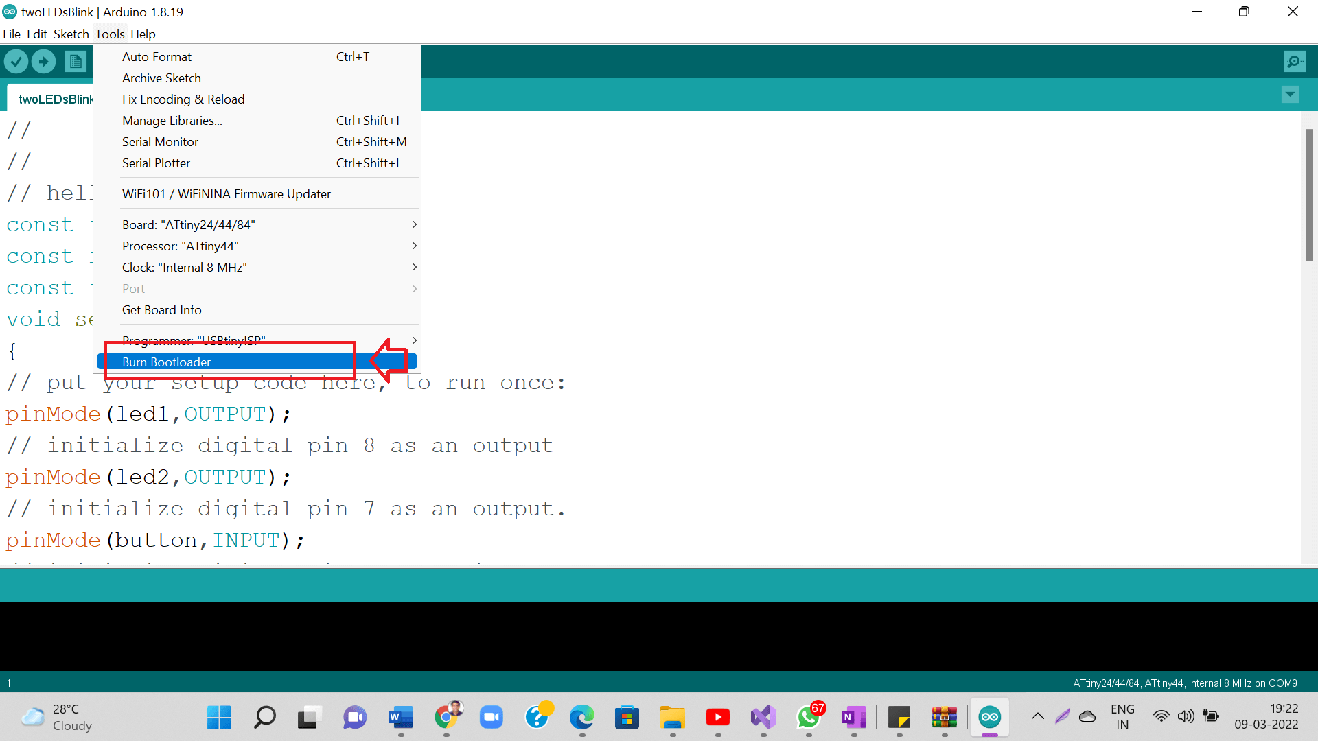
Burn bootloader as shown below.
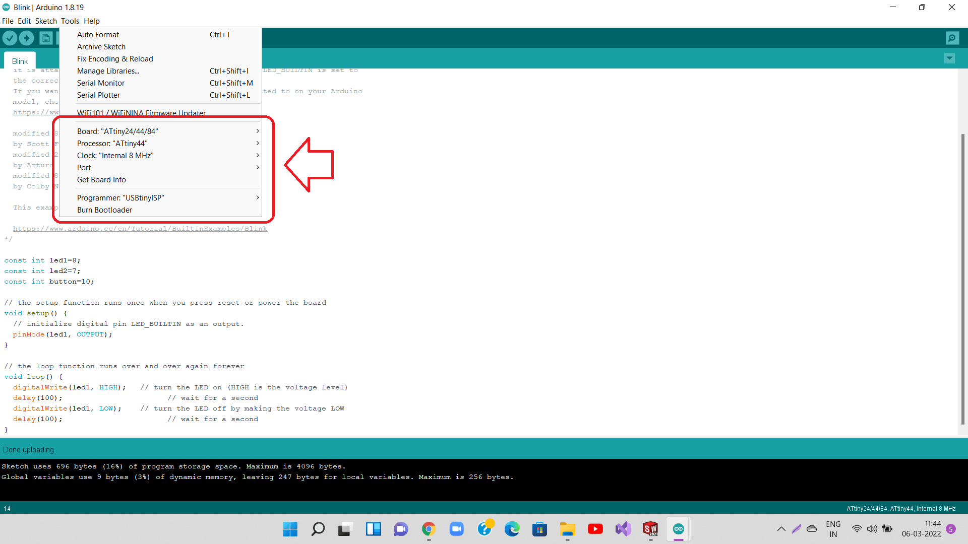
This is how it will look like after selecting your board, processor, programmer, etc.
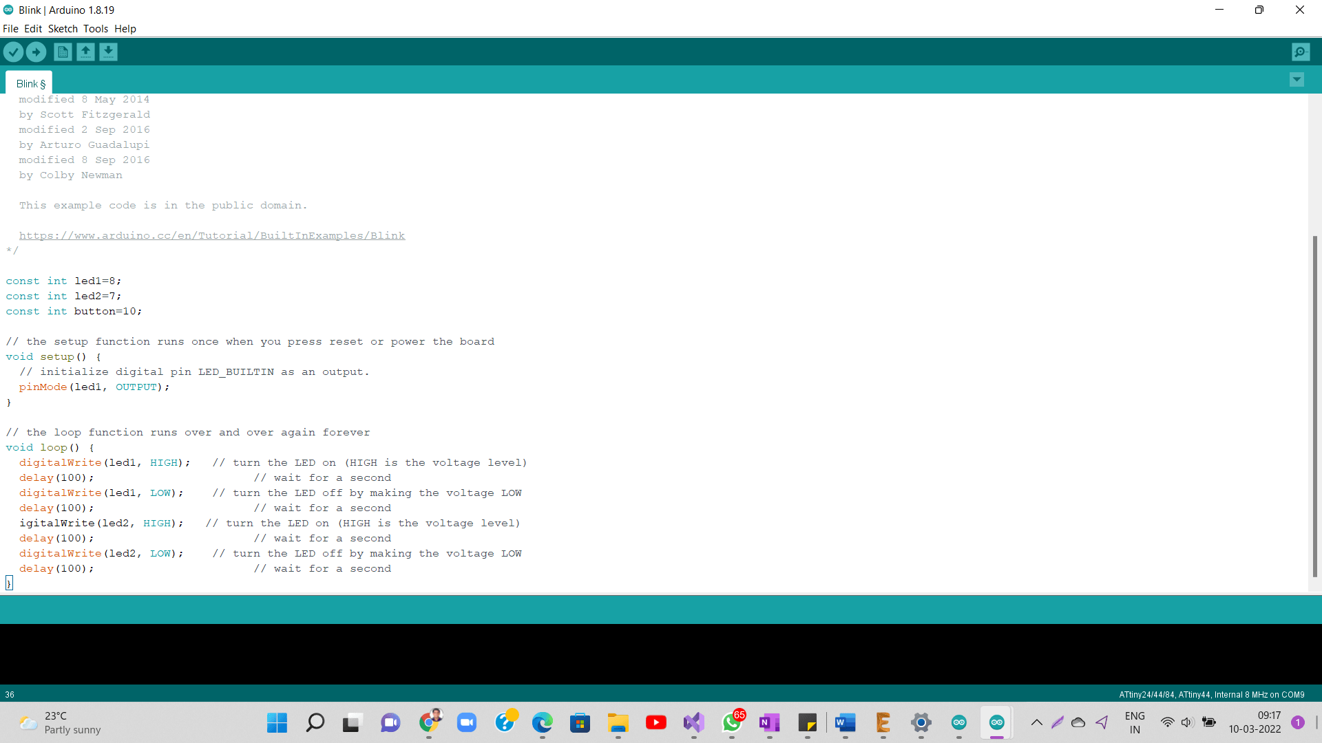
Following are snapshots of my program. You can download and use them from the 'Download Files' section.
LED blinking on Hello-world Board with Push button
In group assignment- We were able to test the DSO, variable power supply, multimeter with different boards (our own hello-world board, arduino uno), usinf different components like resistor, capacitor, etc. and with different programs. In individual assignment- I was able to design PCB layout quite in time. That gave me enough time to mill and stuff the board. I was also able to program my board successfully using arduino IDE.
What went wrong
In group assignment- There is nothing major that we did wrong in the group assignment, the only thing we could have done better here was time management In individual assignment- There was an issue with program uploading to my board in first few attempts. I used USB extended cable and it worked fine. I did not get much time to check different programs using my board. I will do that in coming week.
- I would be more creative in designing layout of my PCB. I will learn to use vector file inside Eagle to generate traces as per some graphics
- I would program my board using different programs apart from blink and would add more LEDs.
Learning Outcomes
- I learned Eagle PCB design software this week
- I learned basics of electronics and different electronic components, their properties, why do we use them, etc.
- I learned how to use multimeter to test different electronic components and measure their parameters
- I learned to operate Digital Storage Oscilloscope (DSO) and variable power supply