
Assignment#7: Computer-controlled Machining
This assignment is about documenting what I learned in Computer-controlled Machining that includes understanding basics of computer-controlled machining, safety training, large format CNC machining of cardboard, Medium Density Fiberboard (MDF), Medium Density Overlay (MDO), Oriented Strand Board (OSB), tooling required for machining, speed and feed requirements, fixturing, sacrificial layer, importance of dust collection, flexures, living hinges, kerfing, steam bending, toolpaths, dog bones, nesting, etc. I have documented how I designed the rack for vinyl cutter in our lab, how I cut and assembled these parts. I am also documenting what went well, what went wrong, how I would do things differently in next assignment and my learning outcomes.
Objectives of Individual Assignment:
- Make (Design, mill and assemble) something big (meter-scale)
- Extra credit: Don't use fasteners or glue
- Extra credit: Include curved surfaces
My Hero shots for this week
 |
 |
 |
 |
Click here to go back to the top
Basics of Computer controlled machining
Computer-controlled or CNC machining is a manufacturing process in which pre-programmed computer software dictates the movement of factory tools and machinery. The process can be used to control a range of complex machinery, from grinders and lathes to mills and routers. With CNC machining, three-dimensional cutting tasks can be accomplished in a single set of prompts. A CNC machine processes a piece of material (metal, plastic, wood, ceramic, or composite) to meet specifications by following coded programmed instructions and without a manual operator directly controlling the machining operation.
A CNC machine is a motorized maneuverable tool and often a motorized maneuverable platform, which are both controlled by a computer, according to specific input instructions. Instructions are delivered to a CNC machine in the form of a sequential program of machine control instructions such as G-code and M-code, and then executed. The program can be written by a person or, far more often, generated by graphical computer-aided design (CAD) or computer-aided manufacturing (CAM) software. When a CNC system is activated, the desired cuts are programmed into the software and dictated to corresponding tools and machinery, which carry out the dimensional tasks as specified with desired machine parameters such as the speed, feed rate and coordination. In CNC machining, movement is usually directed across X and Y axes. The tool, in turn, is positioned and guided via stepper or servo motors, which replicate exact movements as determined by the G-code. Click here to read more.
CNC Router
A computer numerical control (CNC) router is a computer-controlled cutting machine which typically mounts a router as a spindle which is used for cutting various materials, such as wood, composites, aluminium, steel, plastics, glass, and foams. CNC routers can perform the tasks of many carpentry shop machines such as the panel saw, the spindle moulder, and the boring machine. They can also cut joinery such as mortises and tenons.
A CNC router can be used to produce items such as door carvings, interior and exterior decorations, wood panels, sign boards, wooden frames, moldings, musical instruments, furniture. In addition, they see use in industry in the thermoforming of plastics by automating the trimming process. CNC routers can help ensure part repeatability and sufficiently efficient output for production, or allow one-off designs to be made.
CNC routers come in many configurations, from small home-style D.I.Y. desktop, to large industrial routers manufactured for commercial use. CNC routers are used in sign shops, cabinet making, aerospace and boat-making. Although there are many configurations, most CNC routers have a few specific parts: a dedicated CNC controller, one or more spindle motors, servo motors or stepper motors, servo amplifiers, AC inverter frequency drives, linear guides, ball screws and a workspace bed or table.
In addition, CNC routers may have accessories such as vacuum pumps, with grid table tops or t-slot hold down fixtures to hold the parts in place for cutting. CNC routers are typically available in 3-axis and 5-axis CNC formats. Many manufacturers offer A and B axis for full 5-axis capabilities and rotary 4th axis. Common industrial CNC router sizes include 4 x 8 feet and 5 x 10 feet. Many CNC routers today are made of aluminum extrusion which provide great flexibility as this can be shipped from almost anywhere unassembled but also provides size options. Some popular extrusion used are MakerSlide, V-Slot linear rail, and 8020 T-Slotted profile. Click here to read more.
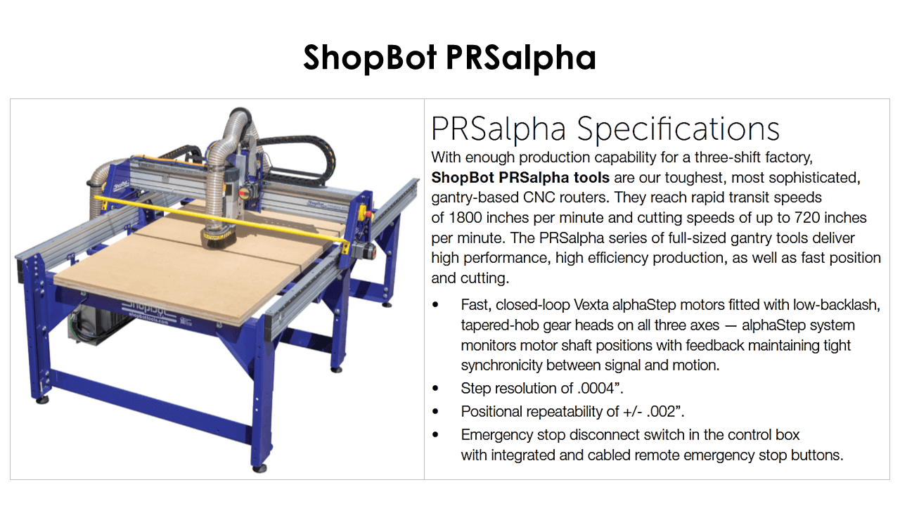
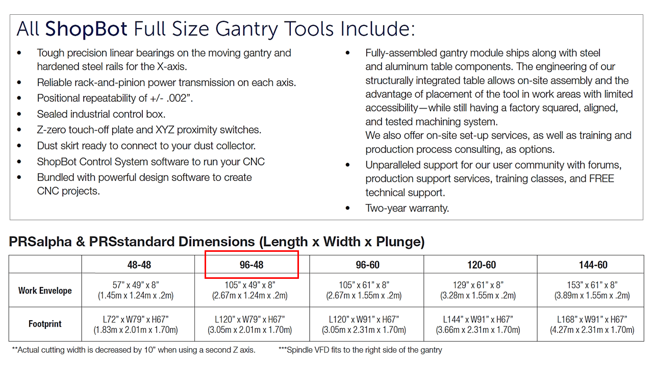
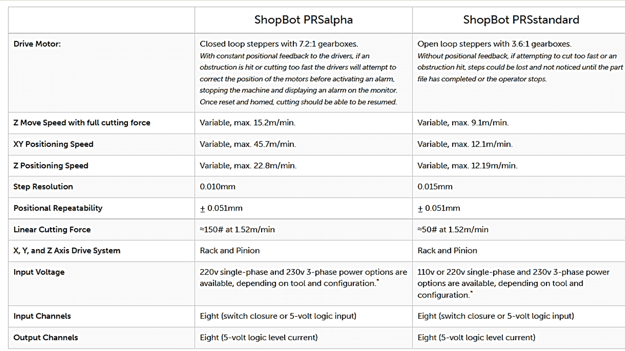
ShopBot PRSalpha
ShopBot PRSalpha (96-48) is one of the ShopBot full size gantry tools that we have here in the Fab lab at college of Engineering Pune. Using advanced technology for CNC cutting, drilling, carving, and machining, ShopBots full size gantry tools are easy to configure and re-configure, easy to learn and use. They reach rapid transit speeds of 45.7 meter per minute and cutting speeds of up to 15.2 meter per minute. The PRSalpha series of full-sized gantry tools deliver high performance, high efficiency production, as well as fast position and cutting.
 |
 |
 |
Basics of ShopBot CNC Router
How to use: ShopBot CNC Router
ShopBot Tutorials
Following are links to some important tutorials in ShopBot
Click here to Download ShopBot Tutorial PDF file.
Click here to go through all of the ShopBot Tutorials.
Lab Safety Requirements and Training
Following are the safety guidelines and requirements that I learned and followed at all times, while operating the shopbot router.
Before operating the machine:
- Do not operate equipment unless you have been properly trained to do so. If you are unsure about the safe operation of a tool or any aspect of a job- ask for help. If you can not do a job safely, do not do it!
- Never work when you are impaired, tired, feeling sleepy or under medications that cause drowsiness.
- Be prepared and have your file ready and plan ahead before using the machine for cutting.
Personal Protection:
- Never work alone. At least two people must be in the lab at all times when operating power tools and equipment. An approved Lab Supervisor must be present.
- You must wear safety glasses with side shields at all times as the toolm material or any other part may break anytime and can injury.
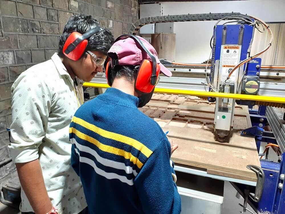
- Hearing protection is recommended as the machine and dust collector makes a loud noise.
- Must wear appropriate apparel- No loose clothing or jewellery, closed-toed shoes, hair tied back.
- Keep eyes, hands, hair and clothing away from the ShopBot and router while it is operating. Tie long hair back. Do not use your hands to hold down parts that may come loose as they are cut out.
- Listen for changes in sound that may indicate a problem while running the tool. ALWAYS be near enough to be able to stop the ShopBot should a problem arise (lift the shield or press stop to stop).
- Use your senses all the time- See, hear and smell.
Shop and Tools:
- Always keep aisles, exits and access to emergency equipment (fire extinguishers, fire alarms, first aid kit) clear at all times.
- Become familiar with how the ShopBot works and the dangers before using it. Ask for help!
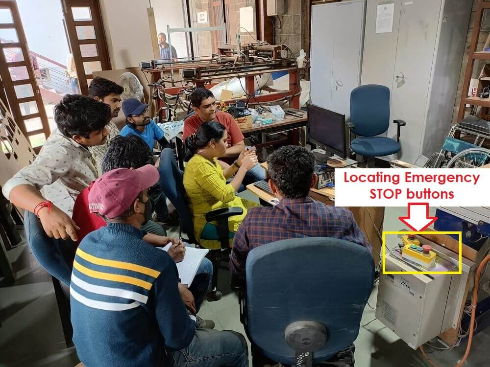
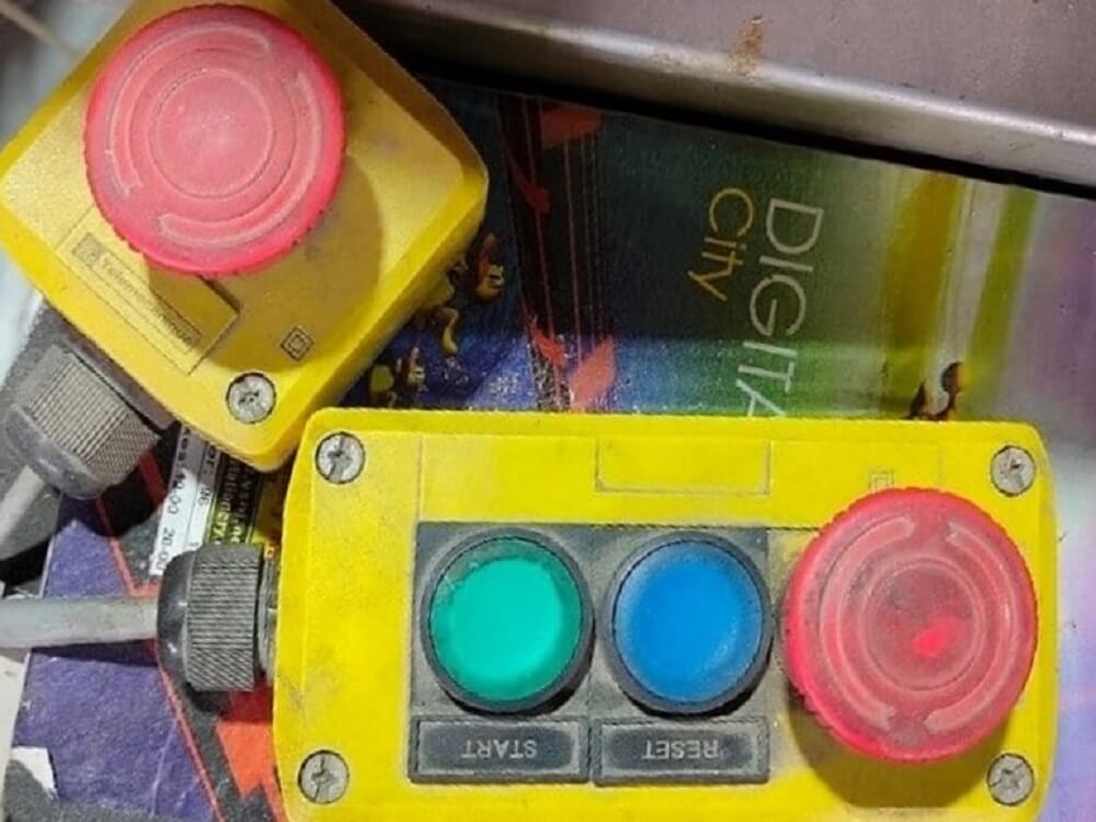
- Identify and locate Emergency STOP buttons for the machine
- Verify the overall condition of the equipment and the material being used (e.g. condition of bits, debris build-up, defects in the tool housing or anything that would compromise the safe use of the ShopBot).
- Keep the area around the machine clean and free of clutter and trip hazards.
- Pay attention to the machine at all times.
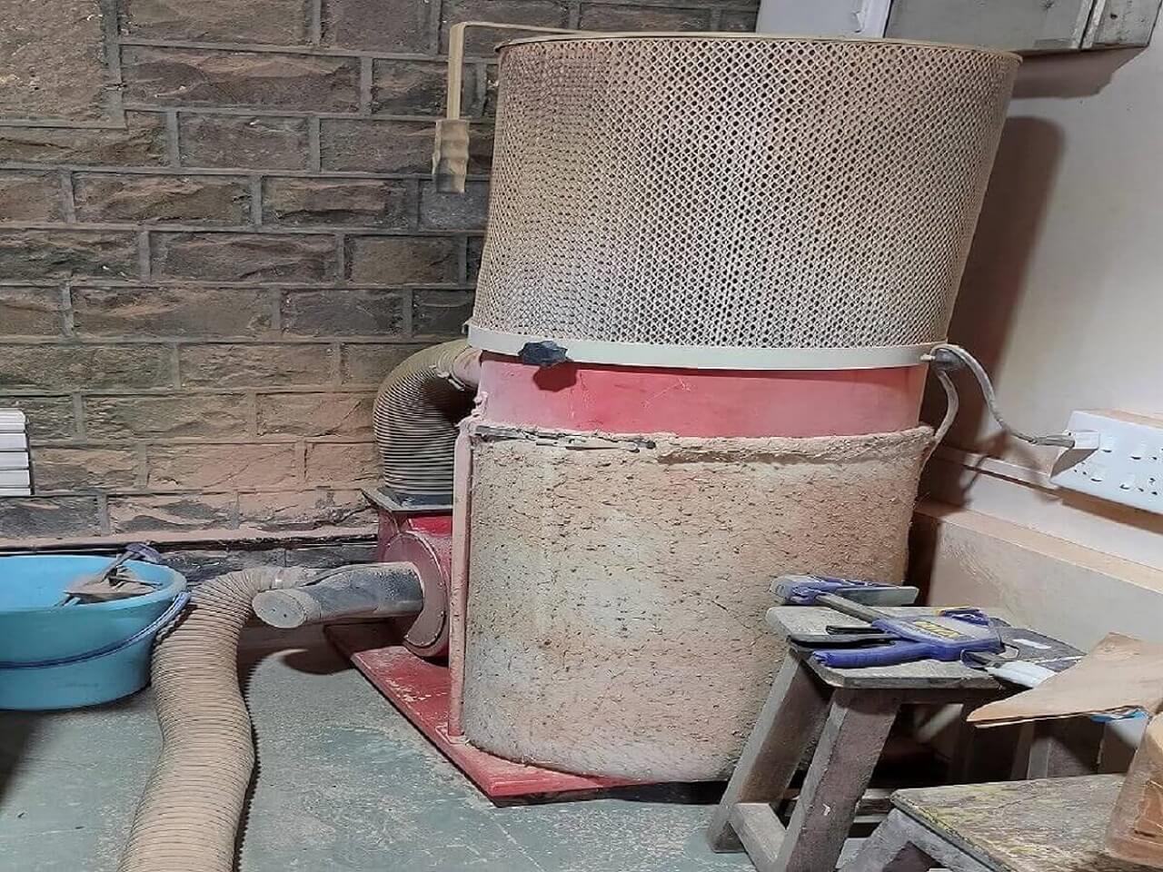
- I learned the importance of dust-collector and what precautions need to be taken care in case of dust-collector.
 |
 |
 |
 |
 |
|
Click here to go back to the top
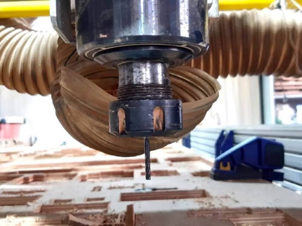
Tooling and Fixturing
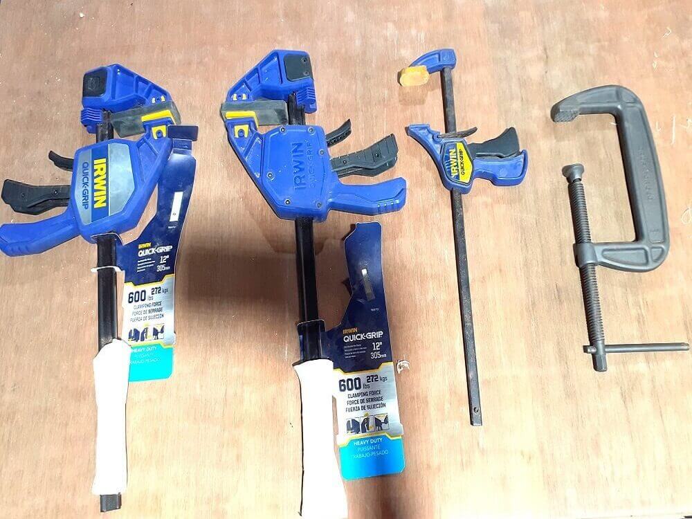
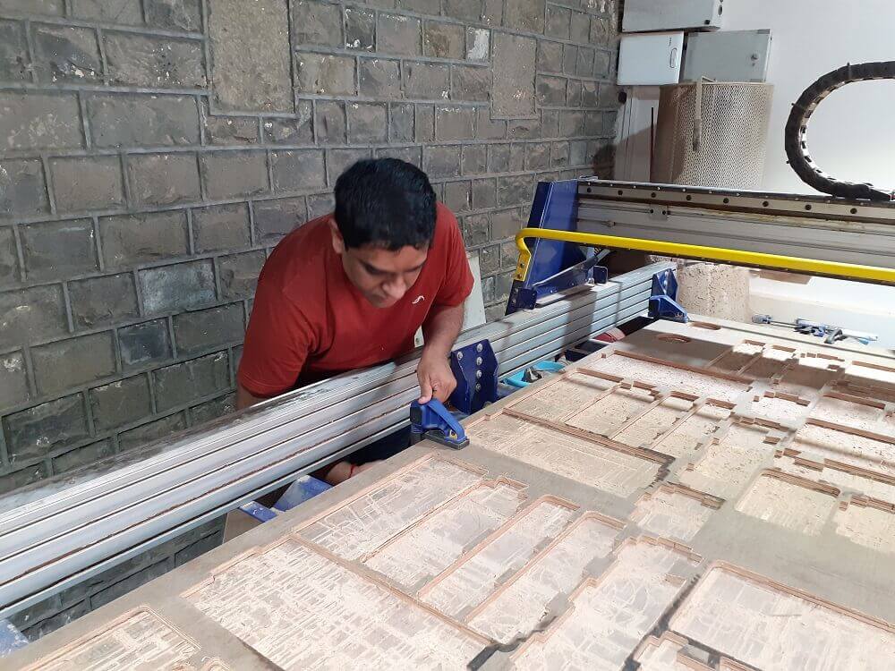
After understanding basics of ShopBot router and safety requirements, I learned the tooling and fixturing requirements for the machine. Clamps are very much required for holding the stock properly on the machine bed. We need to consider the job layout and place clamps accordingly so that the tool does not hit the clamp while in operation. We also did nailing wherever we thought the stock/the cut part will come up during the process. There are chances that tool will hit on to stock and/or the cut parts and break. We also changed the tool from the machine to learn the tool changing process.
 |
 |
 |
 |
 |
 |
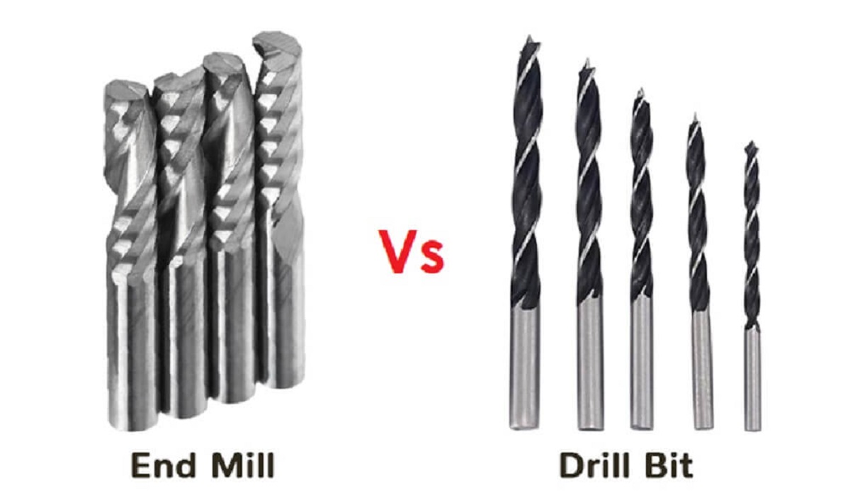
End Mills vs Drill Bits
CNC machining is a subtractive process that uses rotational cutting tools called "end mills" to remove material. An end mill, while similar in appearance to a drill bit, is far more versatile. However, in practice the terms "bit" and "end mill" are often used interchangeably.
Here are the key differences:
- Drill bits are designed to plunge directly into material, cutting axially and creating cylindrical holes. End mills are typically used for horizontal carving and cut laterally.
 |
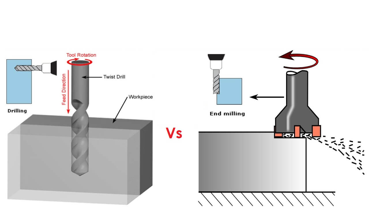 |
- Additionally, most mills are "center-cutting", meaning they are able to cut both axially and laterally. This is due to cutting flutes that extend to- and protrude from- the end face and enable plunge cutting. To minimize tool breakage and stress on the material being cut, most CNC software will "ramp" the end mill slowly into lateral cuts.
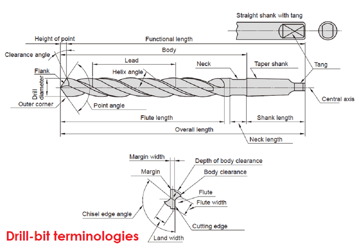
- Next, the milling cutter is very short. The two cutting edges of the outer circle have clearance angles, which can play a cutting role. They intersect at a point and there is almost no chisel edge. The drill bit is relatively long, and the two blades of the outer circle have no clearance angle, which only reduces friction. The two blades do not intersect at one point, and there is a chisel edge, which has many dimensions every 0.1 mm
- The most intuitive difference is whether there is an apex angle (or point angle) at the tip. The drill bit is to make holes, so there must be an apex angle to help orientate, while the milling cutter is to mill the plane, mainly relying on the edge, no apex angle.
- The side edge of the milling cutter has a relief angle, so it can be cut sideways. The side edge of the drill has no relief angle, so it cannot cut laterally.
 |
 |
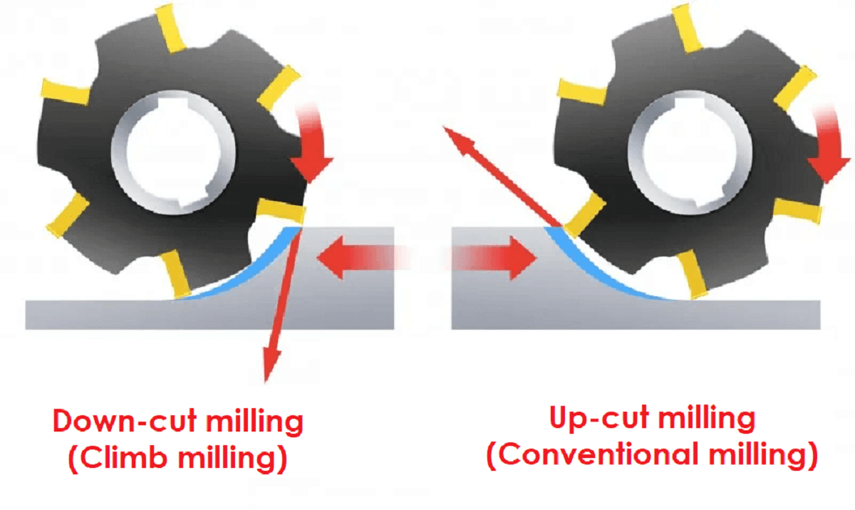
Downcut Vs Upcut End milling
In Downcut milling (climb milling), the cutting tool is fed with the direction of rotation. Down milling is always the preferred method wherever the machine tool, fixture and workpiece will allow. In peripheral down milling, the chip thickness will decrease from the start of cut, gradually reaching zero at the end of cut. This prevents the edge from rubbing and burnishing against the surface before engaging in the cut. Downcut tools produce a smooth upper surface. They are ideal for pieces that have been previously engraved or v-carved and cannot be flipped to hide tearout. In addition, as downcut mills pack the chips into the cut path, they can be used instead of tabs to hold down a workpiece and keep it from moving.
In upcut milling (conventional milling), the feed direction of the cutting tool is opposite to its rotation. The chip thickness starts at zero and increases toward the end of the cut. The cutting edge has to be forced into the cut, creating a rubbing or burnishing effect due to friction, high temperatures and, often times, contact with a work-hardened surface caused by the preceding edge. All this reduces the tool life. upcut mills eject chips towards the top of the workpiece, producing a cleanly cut bottom surface. The downside is possible surface splintering or "tearout" on the top surface as the chips are ejected upwards.
 |
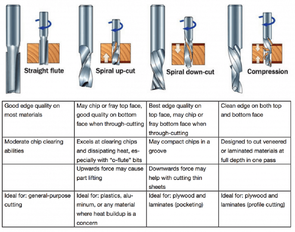
Flute type: There are four basic flute types: Straight, spiral up-cut, spiral down-cut, and compression. Each type has its own advantages and disadvantages.
 |
Tip Shapes and Applications
Each end mill tip shape is designed for a particular purpose. Some common cutter shapes are ballnose, fish tail, surface planing, v-carving, and straight.
Ballnose mills produce a rounded pass and are ideal for 3D contour work, while fish tail cutters will produce a flat surface. V-bits produce a "V" shaped pass and are used for engraving, particularly for making signs.
Flutes and Chipload
Flutes are the helical grooves that wrap around the sides of the end mill. Each flute has a single tooth with a sharp cutting edge (although there can be more than one) that runs along the edge of the flute.
As the tooth cuts into the wood, each flute whisks away a small section or "chip". The fewer the flutes, the more material that is ejected with each tool rotation. The overall cutting depth should never exceed the length of the flutes on an end mill. If cutting deeper than the length of the flutes, the tops of the flutes will be blocked and chips will not clear, building up heat and reducing tool life.
Chipload is the thickness of a machined chip as cut by a specific tool type. More flutes create a smoother surface finish, while fewer flutes remove material fastest, but make rougher cuts.
Proper chipload is important because chips dissipate heat. Hot cutters can lead to suboptimal results, including burned wood, a poor edge finish and dull tooling. If you are machining a material like HDPE plastic, you want to use an "O" or single flute bit to clear the chips away as quickly as possible or heat will build up melting the plastic, which will "reweld" to the tool.
Feeds and Speeds
The speed at which we move a cutter across the material is called the "feed rate". The rate of rotation is called the "speed" and is controlled by how fast the router or spindle turns the cutting tool. Both feed rate and spindle speed will vary based on the material being cut. A general rule of thumb is that you want to move the tool through the material as fast as possible, without sacrificing surface finish. The longer the tool rotates in any one place, the more heat that builds up. Heat is your enemy and can burn your material or radically decrease the life or your cutting tool.
Feed rate vs spindle speed: 1) Spindle speed that is too fast paired with a slow feed rate can result in burning or melting. 2) Spindle speed that is too slow paired with a faster feed rate can result in dulling of the cutting edge, deflection of the end mill and possibility of breaking the end mill.
A challenge of getting a good CNC cut is in selecting the best cutting speed (feed rate) and router/spindle RPM (speed of rotation). Feeds and speeds are a critical part of machining and should be fully understood before deviating from recommended settings. A primary concern of machining is chip load, which is a representation of the size of the chips produced during cutting.
The goal is to get the maximum chip load possible to increase productivity, reduce heat, and prevent premature dulling. When chip load is too small, bits will get too hot and dull quicker. When chip load is too high, the tool will deflect creating a bad surface finish and, in extreme cases, chip or break the bit.
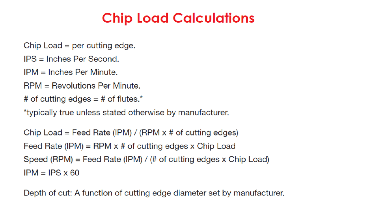
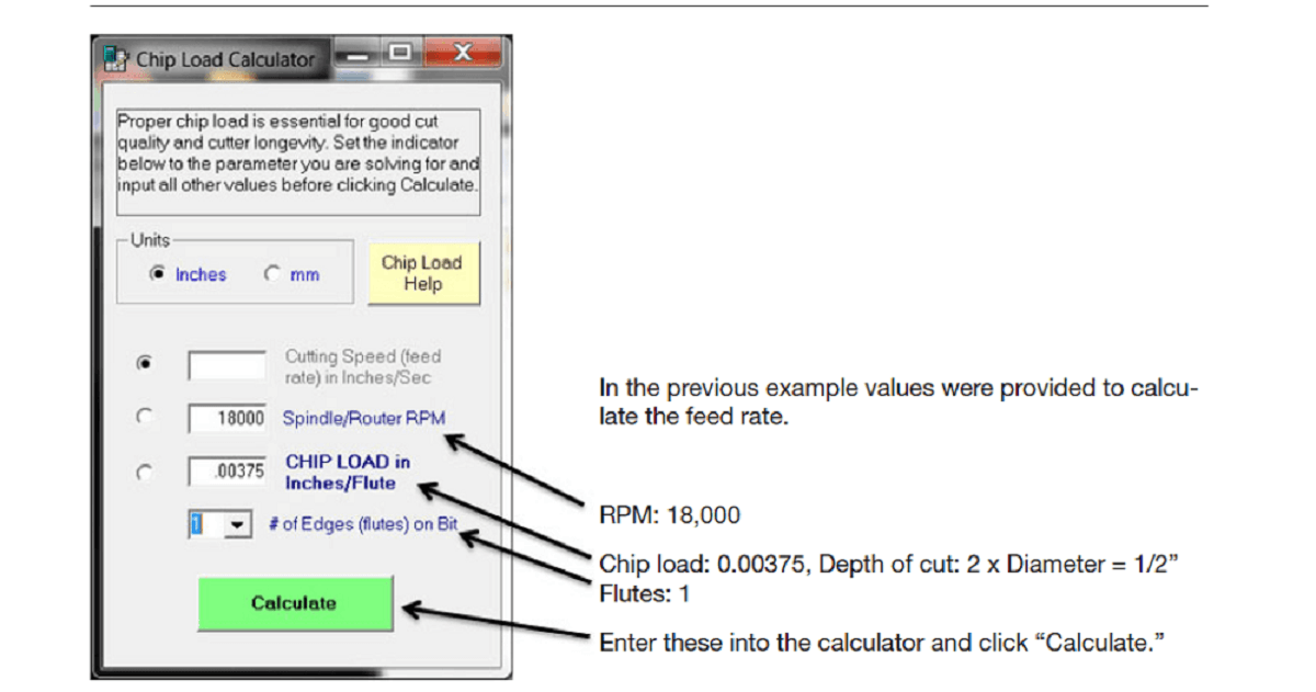
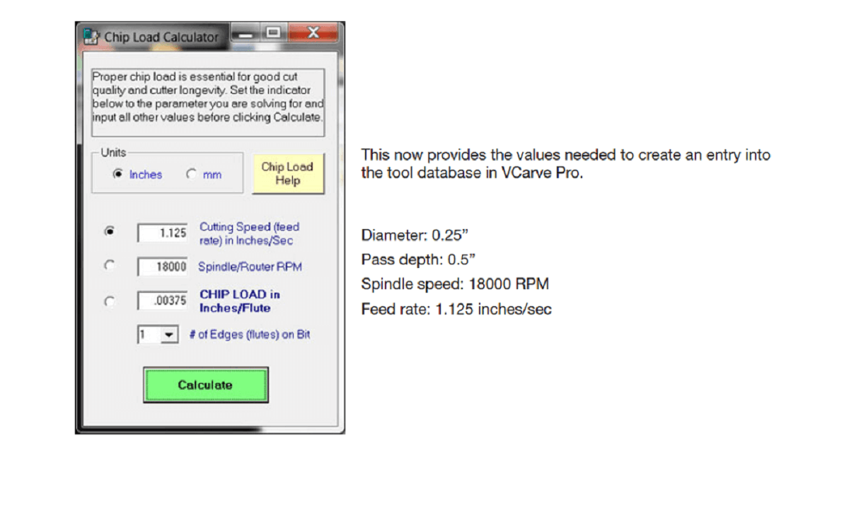
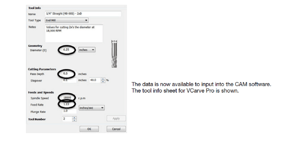
Chip load is a function of three different parameters: feed rate, RPM, and number of flutes on the tool. Chip load is the thickness of the chunk of material taken by a tooth of the cutter. This is determined by how fast the cutter is moving forward into the material and how fast it is turning (Chip load = Feed Rate / [RPM x number of flutes]). This formula provides a starting point for determining the most suitable parameters for any cutting situation.
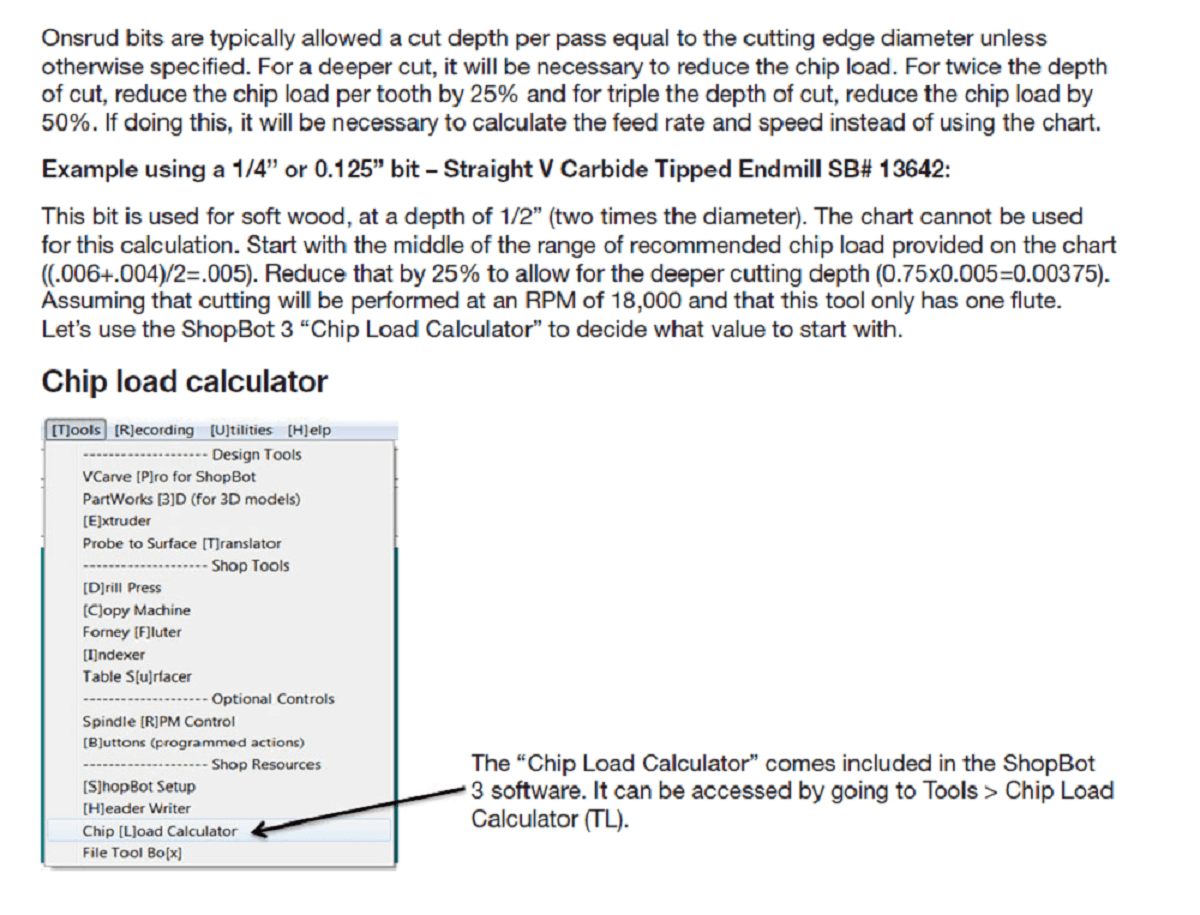
Using below method in ShopBot, we can calculate the speed, feed rate after knowing the chip load.
 |
 |
 |
 |
 |
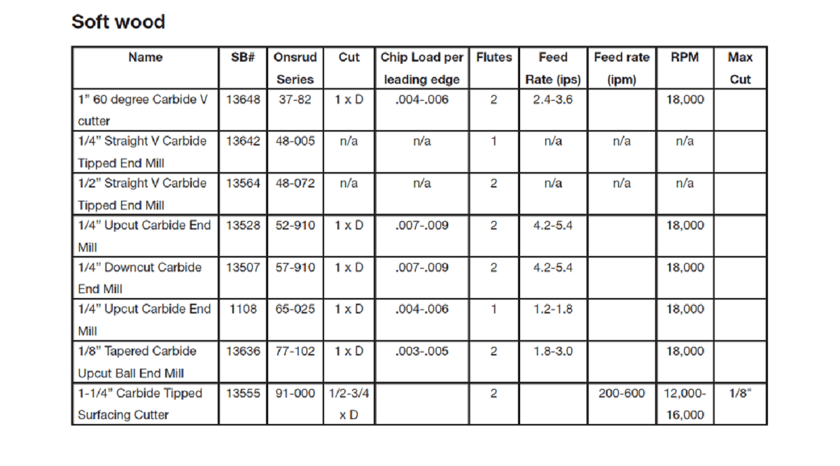
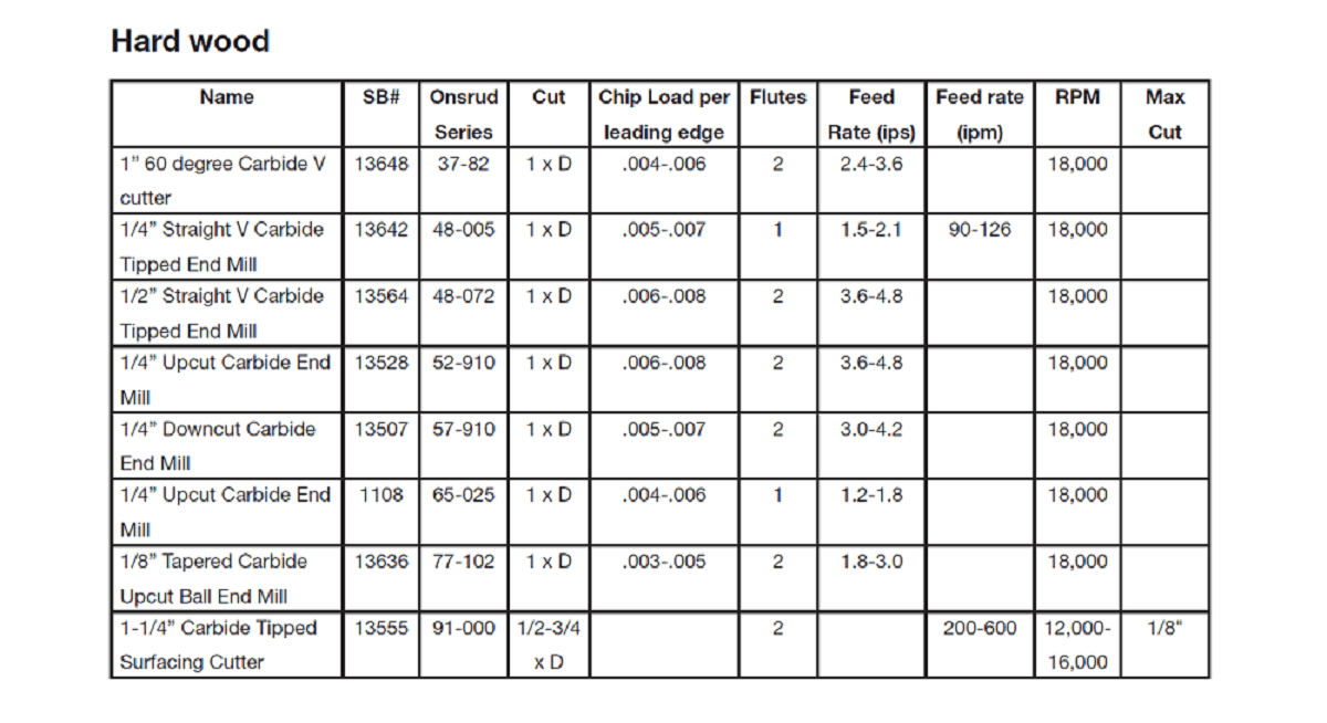
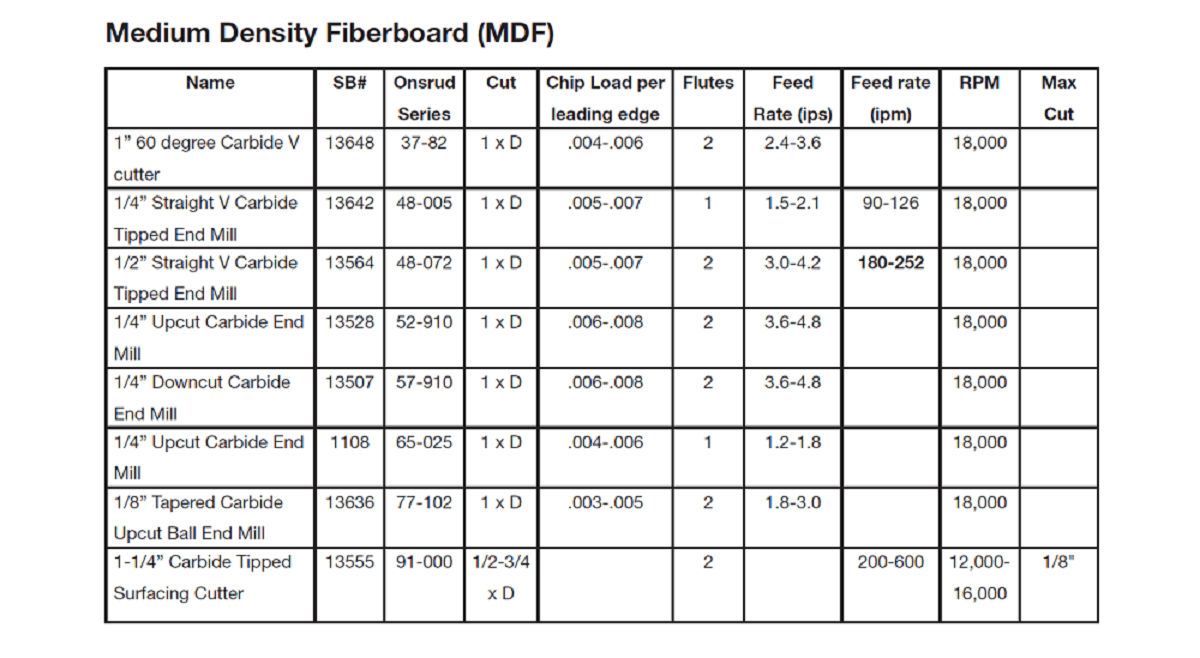
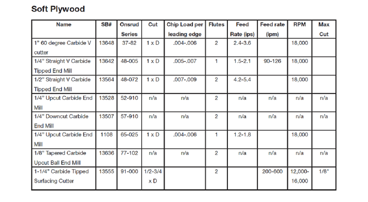
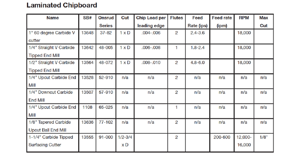
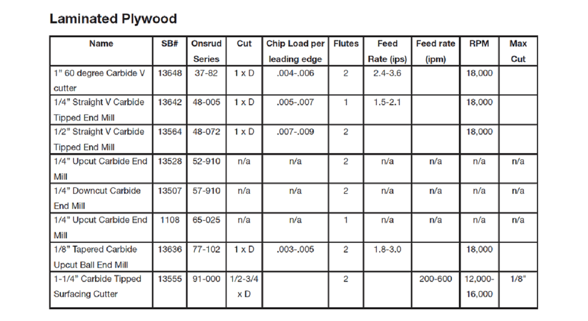
Feeds and Speeds Chart for Different Materials
Following are the speed and feed charts for different material recommended by ShopBot.
 |
 |
 |
 |
 |
 |
Dogbones and why are they needed
You are probably familiar with "regular" fillets, but did you know that there is also a DogBone Fillet?
 |
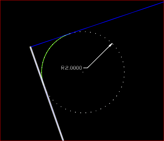
What is a regular Fillet? A fillet is used to reduce the sharpness of corners. You can modify corners with fillets (either a chamfer or curve). A "regular" fillet creates an arc that is always inside to the edges (see image below).
What is the problem with a regular fillet? There are cases where an outward curve may be required. For example, when using a CNC (Computer Numerical Control) router or machine. In contrast to additive manufacturing (3D printers), a CNC machine uses subtractive manufacturing to create the end product. In other words, a CNC machine removes material instead of adding material.
Just like 3D printers, instruction files are given to a CNC machine as a G-Code. G-Code is the language that defines the "How" for a machine controller. It tells the motors where to move, how fast to move, and what path to follow. Vector files such as DXF are used to create G-Code files.
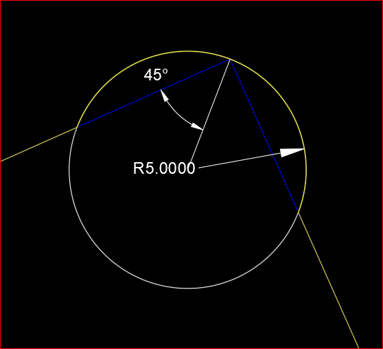
However, the problem for a CNC machine is that the inner corners can never be sharper than the diameter of the cutting tool. This is because the router bits are round. It is not possible to get orthogonal corners at perfect right angles when cutting out the sheet materials like MDF or plywood with a CNC machine, so instead, these corners will be rounded inwards.
This can cause problems when mating parts as the part tooled might not fit in the formed hole or slot as shown below:
 |
 |
 |
What is the solution? A DogBone Fillet is a solution to this problem. Although "DogBone" is a commonly used term in the field of CNC Cutting and milling, the first image that came in my mind when I heard the word "DogBone" is my favorite childhood cartoon series of Tom & Jerry.
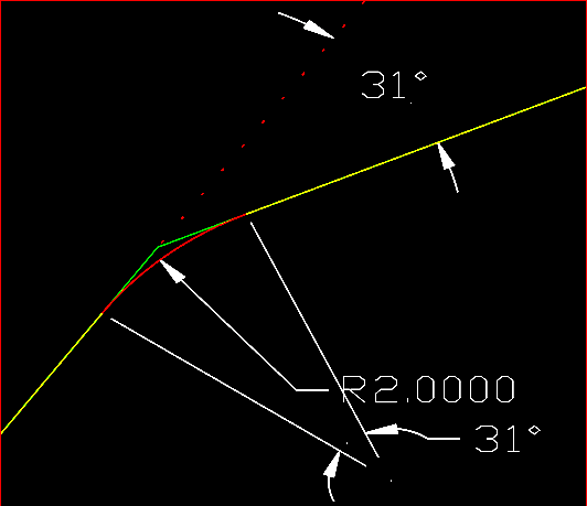
How is a DogBone Fillet diffrent to a normal Fillet? The DogBone Fillet command is different to a normal Fillet command because it creates a circular arc that is outside of the edges. The point of intersection for both edges is actually the mid-point of the arc. By introducing DogBone Fillets, the object fits better into the slot:
 |
 |
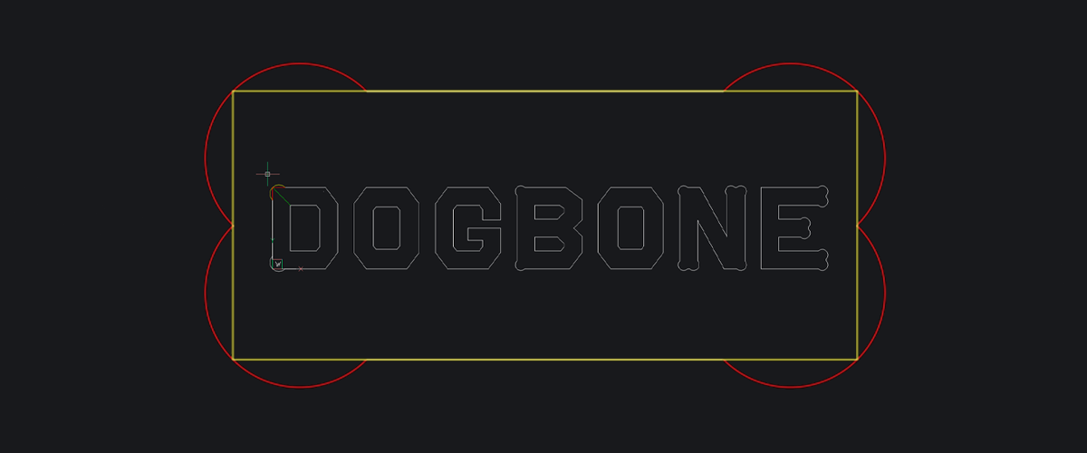
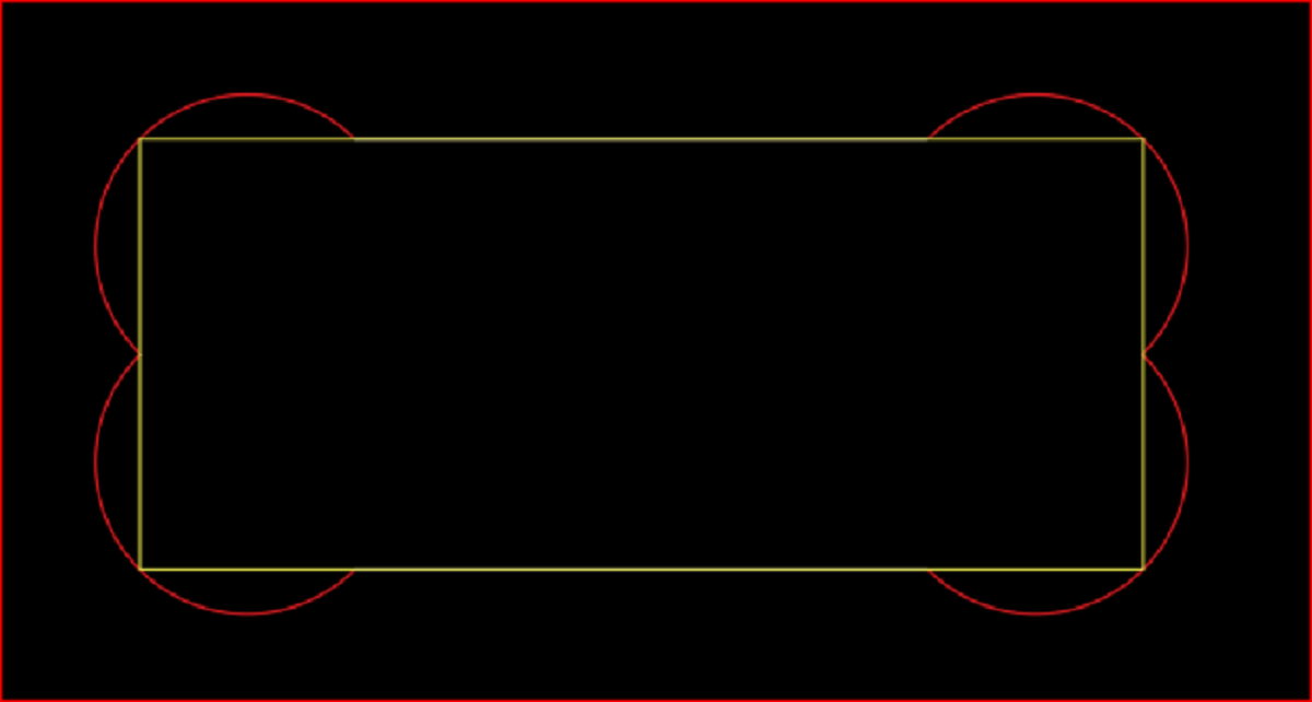
Why is it called a DogBone Fillet? If DogBone Fillets are created at each corner of a rectangular block, it really looks like a Dog-Bone!
 |
How do I add Dogbone Fillet to parts?
I can either draw these in CAD geometry or use Fusion 360 to create dogbones as shown in the video below.
Toolpaths
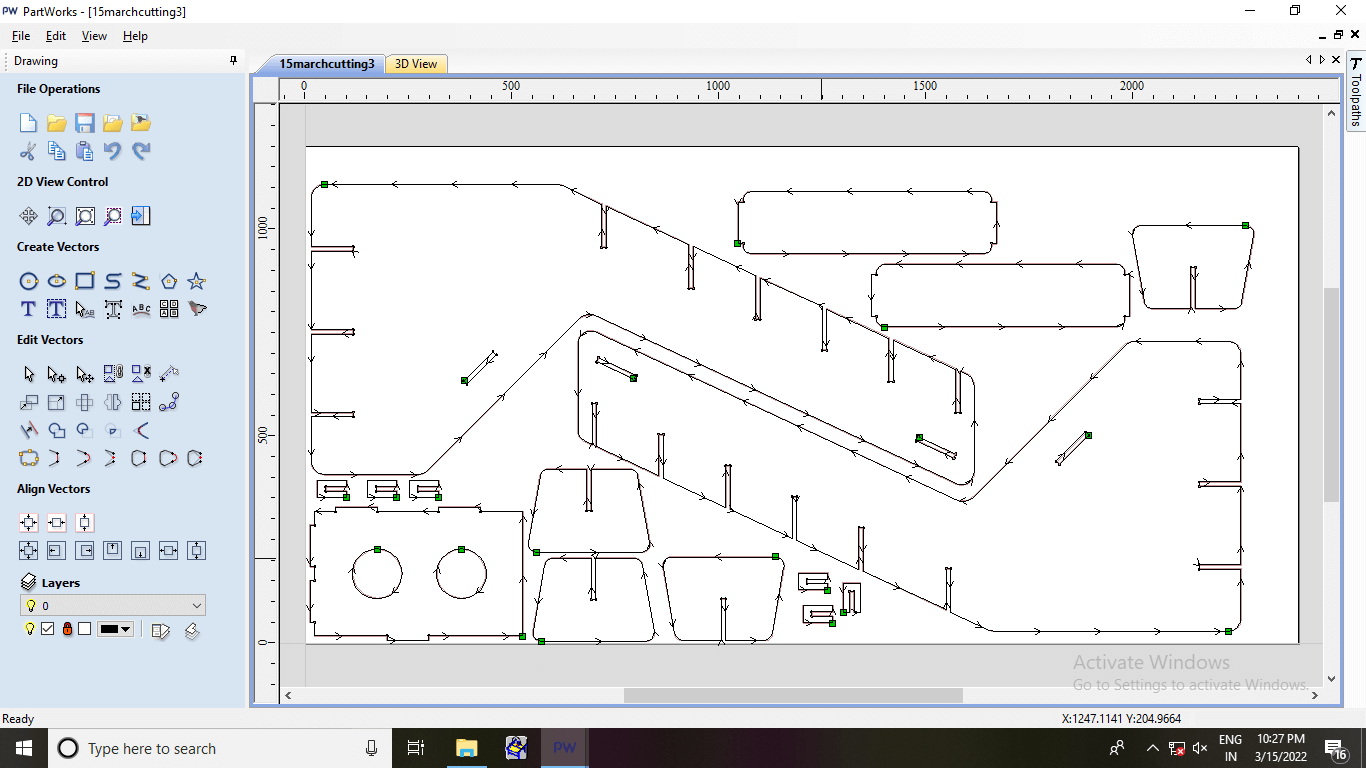
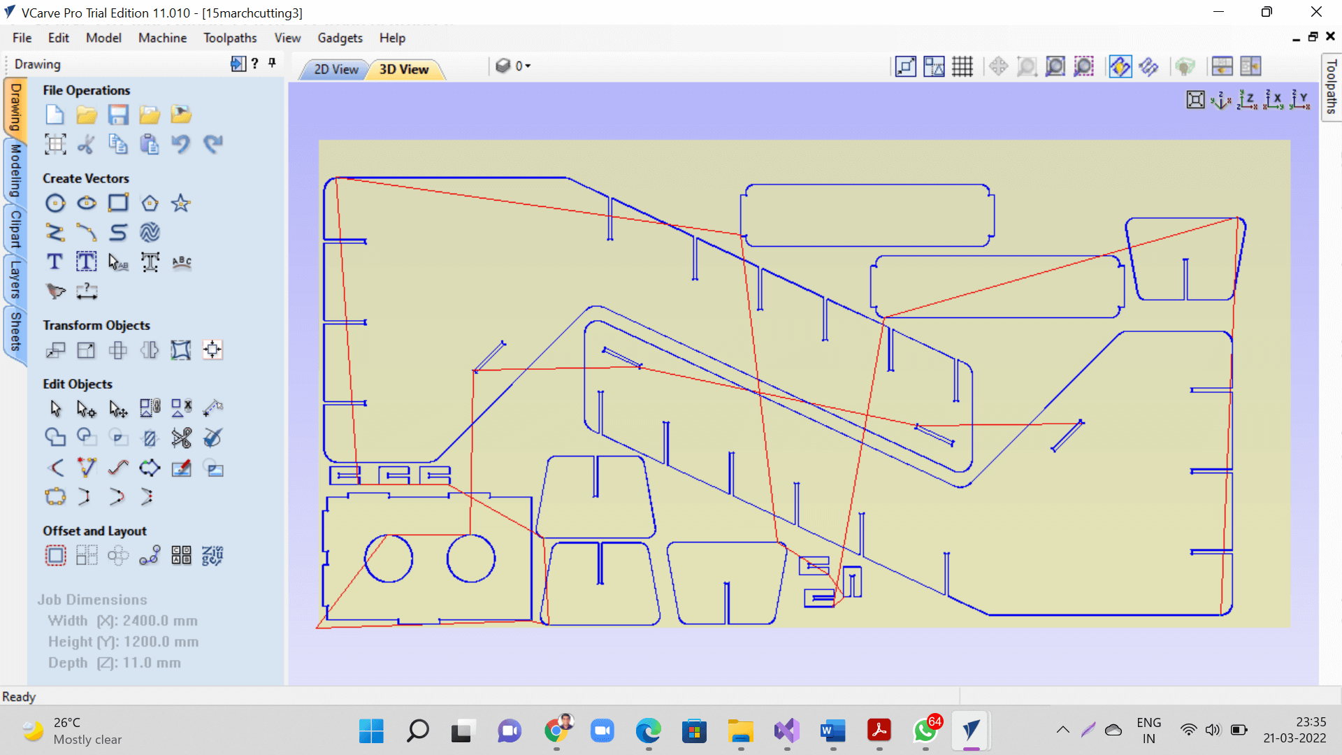
We create toolpaths in PartWorks or Vcarve softwares as shown below.
 |
How to create Toolpath in Vcarve
Nesting
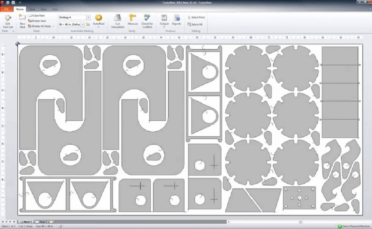
Nesting is a method for arranging parts to minimize cutting time and material waste. Imagine using the outline of your hands to cut out parts. Hold them side by side and look at the space they fill. Now interlace your fingers and watch how the space shrinks. That's nesting, a while the idea seems simple, the algorithms needed to figure it out have been around for around 80 years.
Nesting started with the "rucksack problem": determining how to pack the most odd-sized objects into a fixed space. Think about packing for a long trip when you can only bring one piece of carry-on luggage, or a shipping clerk at Amazon trying to find the smallest box that holds your order.
Nesting algorithms can also solve the "best fit" problem. Imagine trying to figure out how to cut a group of random length pieces out of fixed-length boards, bars, or extrusions to minimize waste. Extend this to high-volume manufacturing, and the need for nesting tools becomes evident.
Nesting can do more than just juggle objects on a 2D layout. Different tools allow you to minimize travel movements of a hot end or CNC cutter, share a common cut line across multiple parts to eliminate skeletons, and cram multiple parts into the working volume of a 3D printer. Expensive tools and skilled laborers help make nesting critical to production efficiency and cost savings.
If you work with subtractive CNC (routers, milling machines, laser cutters, waterjet, or plasma cutters), you'll benefit from 2D nesting, especially if your workflow supports SVG files. Additive manufacturing, such as 3D printing can also benefit, but at the cost of a much higher learning curve and more complicated software.
 |
Nesting software
Below are a few common and popular nesting software options:
Deepnest: Deepnest is another open-source nesting product, in this case optimized for laser, plasma, and water jet cutters. It runs on Windows, Mac, and Linux. It reads DXF, SVG, and CDR files, and writes to DXF or SVG. It offers cut line merging and part-in-part layouts to maximize material use and minimize cutting time. Click here to visit Deepnest website.
SVGnest: SVGnest is free open-source software available for download from GitHub. Described as a browser-based vector nesting tool, the software claims to work for arbitrary containers and concave edge cases and performs on-par with existing commercial software. It's limited to SVG inputs and outputs. Click here to visit Deepnest website.
Materials
There are many different types of plywood and fiberboard sheet goods. These are engineered wood products made out of wood plies or wood fibers. Types of fiberboard include particle board, medium-density fiberboard (MDF), and hardboard. We will see each one of these separately now.
A. Plywood
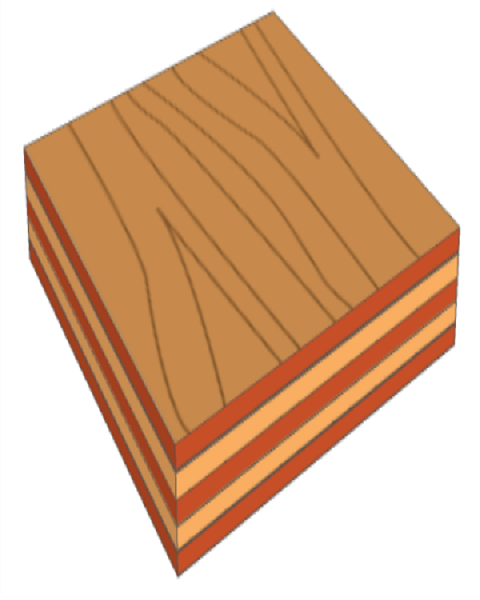
Plywood refers to a board of wood that is produced by arranging thin sheets of wood by applying formaldehyde, melamine or phenolic glue. The glue is liberally applied on the thin sheets or ply of wood as they are commonly called and pressed under high pressure. This ensures that the layers do not split even when hammered with a nail. There are a number of factors that would determine the quality of the plywood and the plywood grades. Plywood is a composite material made up of thin layers or "plies" of wood veneer. The plies are glued together with the wood grain of adjacent layers rotated relative to one another.
There are several important benefits to the cross-grain orientation of the layers:
- It reduces expansion and contraction of the panels due to moisture changes in the atmosphere. This provides much improved dimensional stability over hardwood.
- The strength of the panel is consistent across all directions.
- The wood is less likely to split when nailed or screwed near the edges of the parts.
 |
 |
How plywood is made
The factors that determine the quality of the plywood
The factors that determine the quality of the plywood which is important for assigning plywood grades as well include:
Overlappings- This is assessed by viewing the side profile of the plywood. The lesser the overlapping of sheets in the plywood, the better is the quality of the plywood.
Core gaps- This is again estimated by viewing the side profile of the sheet. It is indeed common for the plywood boards to have gaps between the different layers of ply that are bonded together. If it is greater than 2mm-3mm, it is indicative of poor quality and thereby fall under the lower plywood grade listing.
Nail holding capacity- This feature has got to do with the functionality of the plywood board. if the plywood chips or splits, it is indicative of poor quality.
Weight- The heavier, the board is, the better is its quality. Eucalyptus boards are considered to be heavy and of a higher quality.
Glue- The type of glue used for bonding the plies have a considerable role in determining whether the plywood is meant for exterior use, interior use or for use both in interiors and exteriors.
Certifications and standards of plywoods in India
In India, the plywoods are certified by the Indian Institute of standards. According to them, the various standards stand for different plywood grades, which includes:
IS: 303- which is for commercial ply. Click here for BIS Manual. Click here for standards.
IS: 710- which is for Marine Ply. Click here for BIS Manual. Click here for standards.
IS: 1659- which is for block boards. Click here for BIS Manual. Click here for standards.
IS: 2202- which is for flush door Ply. Click here for BIS Manual. Click here for standards.
IS: 4900- which is for Shuttering plywood. Click here for standards.
Testing of plywoods in India
This goes hand in hand with the certification and the plywood is tested on various properties it claims to feature such as boiling waterproof, fire retardant properties etc and plywood grades are assigned accordingly.
The plywood grades you come across are indicative of the presence or absence of the factors that are markers of the quality of the plywood in the board of plywood in question. It goes without saying, higher the grade, better is the quality of the plywood in question.
Different types of Plywood available in Indian market
Plywood is made from different species of wood and therefore come in different qualities. Also, plywood sometime of same species and number of ply differ from manufacturer to manufacturer because of change in method of manufacturing. Plywood can be classified on basis of different features.
Classification of Plywood on basis of type of wood i.e. Hardwood and Softwood
Hardwood: Hardwood ply are made from veneers or wood obtained from species like Teakwood, Gurjan or Birchwood. Plywood made from veneers obtained from above mentioned trees are also termed as 100% hardwood plywood. Therefore hardwood plywood are expensive product too. Click here to Read more.
Softwood: Softwood ply are made from veneers or wood obtained from species like Spruce-Pine-Fur (SPF) or mango wood. Softwood ply is not as strong as hardwood ply and therefore come for cheaper rate than hardwood of same number of ply. Click here to Read more.
Usually hardwood is used to make plywood for its strength and durability. Nevertheless, some manufacturers use softwood to make plywood to sell at low-cost plywood. There are some, who use a combination of both, softwood and hardwood to make plywood.
Another way of plywood classification, which is most basic and locally accepted is:
1. MR Grade Plywood/Commercial Plywood: The MR here refers to moisture resistant plywood. This is one of the most common types of plywood that carries the Indian standards specification number IS:303. You should not confuse the term moisture resistant with waterproof. MR plywood is by no means waterproof in nature; it can merely resist moisture and humidity. It is also known as commercial ply and features a formaldehyde glue that makes it suitable for use only in the interiors. It can be used to make furniture like TV units, cabinets, wardrobes, sofas, chairs etc., but, it is mostly suitable only for furniture that would be kept away from water.
2. Marine grade plywood: The marine grade plywood differs from the MR plywood in that it is highly waterproof and is quite strong enough to be used in marine applications as well. It includes even making boats. The marine plywood grade acquires these properties owing to the unextended or undiluted phenolic resins that are used for bonding of the plies under pressure. The high-quality wood veneers that have good weight are used in the manufacturing of the plies which make it an ideal choice for making home furniture that would be placed in areas where it would be in constant contact with water, for decks that are closer to the swimming pool, for making boats and ships owing to the properties that prevent it from danger even when it is submerged in water for more than 72 hours. It is suitable for use both in the interiors and exteriors and is the most expensive and high-quality plywood that you can ever have. Click here to Read more.
3. BWR Grade plywood: The term BWR refers to boiling water poof plywood. The glue used to bond the plies is phenolic in nature and is used in making plywood that stays together even if a block of plywood of this grade is cooked in a pressure cooker for about 5 whistles. It is suitable for both interior and exterior use and most suitable for making kitchen cabinets, furniture, paneling etc.
4. BWP: This refers to boiling waterproof boards that are almost similar in construction and glue used to the BWR plywood grades. But, one distinguishing factor is that BWR refers to plywood grades while BWP stands for blockboard grade. Hence, it is important that you do not get confused with the two grades.
Some other types of Plywood
Baltic Birch Plywood: This material is commonly used in CNC routed projects. The wood species is Birch. It's a veneer core material meaning all the plies in the sheet are free of voids. However, you can see in the examples below there are sometimes small defects which you can see in the cut edges. In general however you won't find any large voids as you would in lesser grade stock.
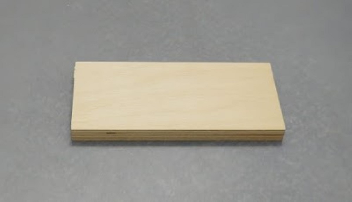 |
Paint Grade Birch Plywood: This is a low-cost product which accepts paint well. Generally the face veneers are not as clean in terms of the grain but they are free of defects so the paint application will be smooth.
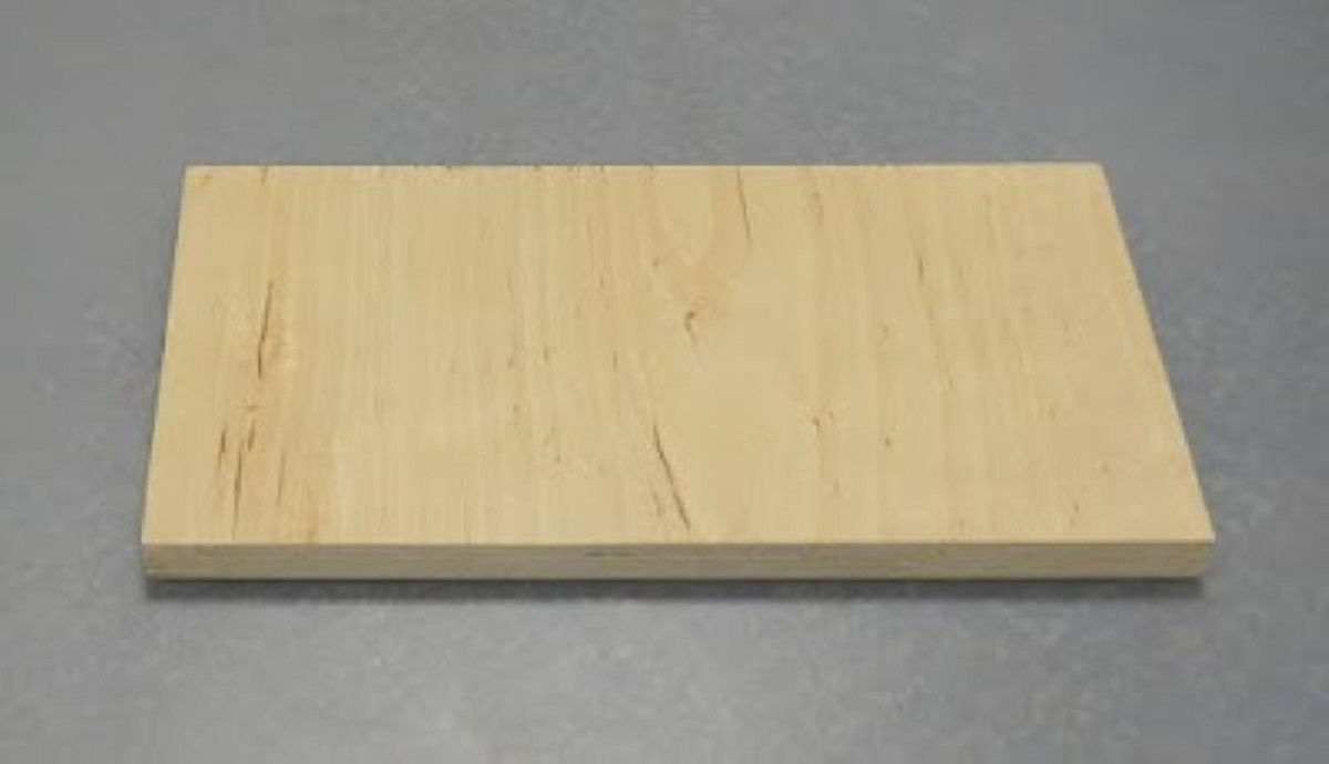 |
CDX Plywood: CDX refers to "C-D Exposure 1". The faces are graded C and D and the glue used in the plywood is exterior glue. While the material is moisture resistant it cannot be exposed to outdoor conditions for an extended period of time. This is a low-cost material commonly used in construction.
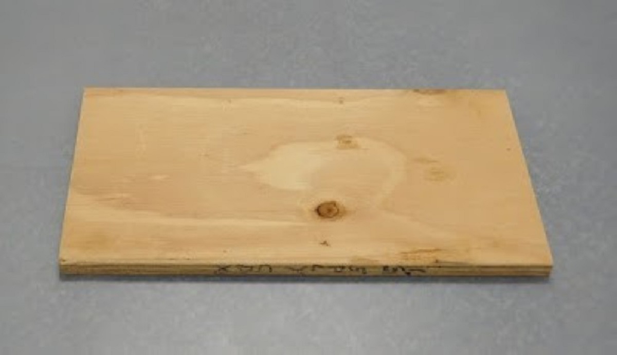 |
Radiata AC Plywood: This is a 7 ply material with thick exterior plies. The A grade side is high quality and has a marked grain pattern to it, similar in appearance to Pine.
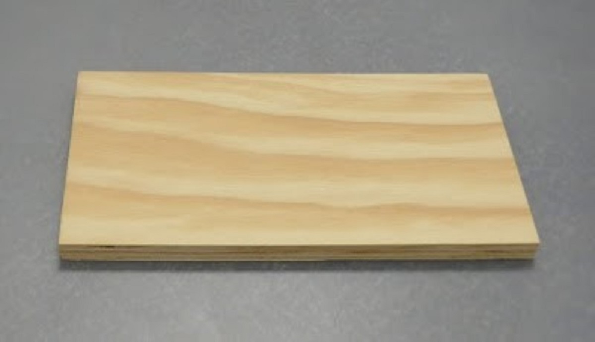 |
Face Veneer Plywood
Below are a few examples of plywood with pre-finished veneers or lower quality material in the internal plies with high quality hardwood face veneers.
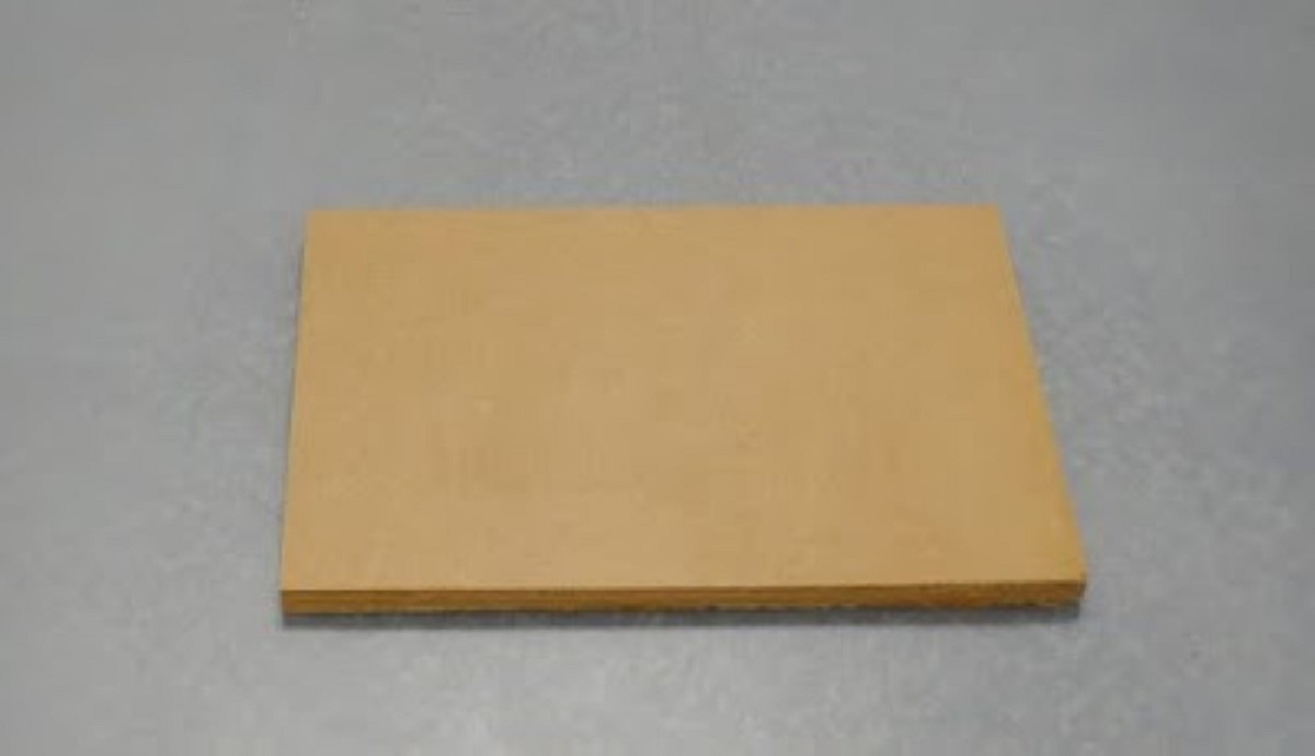
Pre-Finished Baltic Birch Plywood: This is a very high quality material composed of 13 thin plies. Both faces are pre-finished so it is ready for use immediately after cutting. The edges are free of any significant defects (voids).
 |
Red Oak Veneer Plywood: This material has 5 plies and a Red Oak veneer on both sides.
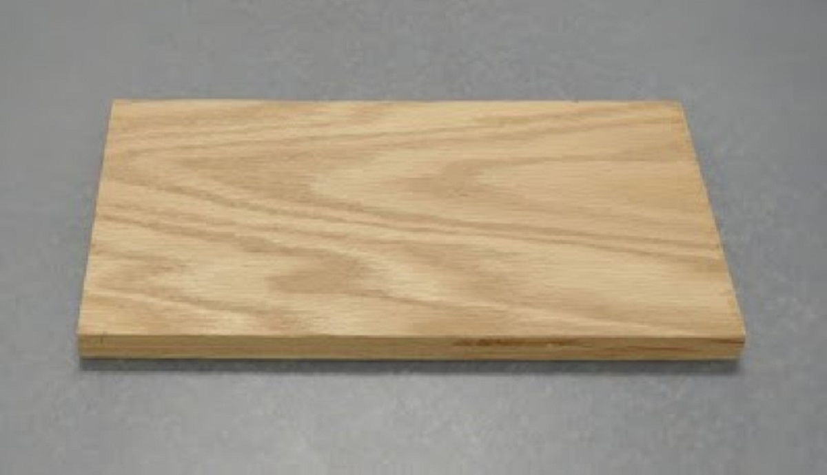 |
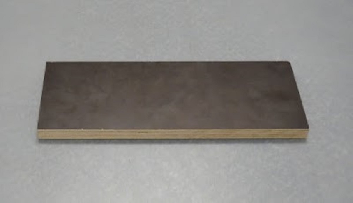
MDO (Medium Density Overlay) Fir Plywood: MDO is an exterior grade plywood with smooth, brown medium-density plasticized overlay. It is made of plywood with a weather-resistant resin overlay bonded to the wood by heat and pressure. T. It's good for accepting paint and resisting exposure to moisture. The painted surface will not show any grain. This material is available with the overlay on one side or two. Click here to Read more.
 |
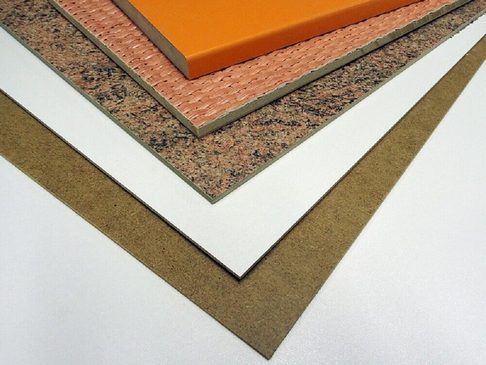
B. Fiberboards
Fiberboard (American English) or fibreboard (British English) is a type of engineered wood product that is made out of wood fibers. Types of fiberboard (in order of increasing density) include particle board or low-density fiberboard (LDF), medium-density fiberboard (MDF), and hardboard (high-density fiberboard, HDF).
Fiberboard manufacture begins with wood chipping: fresh or recycled wood material is cut and sorted to small pieces of similar size. Chips are washed to remove things such as dirt and sand. Metal scraps such as nails can be removed with a magnet placed over a conveyor belt on which the chips move forward. In the case of, for example, MDF (medium density fiberboard) and not particle board, chips are then steamed to soften them for defibration. Small amount of paraffin wax is added to the steamed chips and they are transformed into fluffy fibers in a defibrator and soon afterwards sprayed with adhesives such as urea-formaldehyde (UF) or Phenol formaldehyde resin (PF). Wax prevents fibers from clumping together during storage. Chips in the case of particle board are also sprayed with a suitable adhesive before the next steps. Fibers or chips are arranged into a uniform "mat" on a conveyor belt. This mat is pre-compressed and then hot-pressed. Hot-pressing activates the adhesive and glues the fibers or chips together. Board is then cooled, trimmed, sanded and maybe veneered or laminated. Click here to Read more. Following are the types of fiberboards.
 |
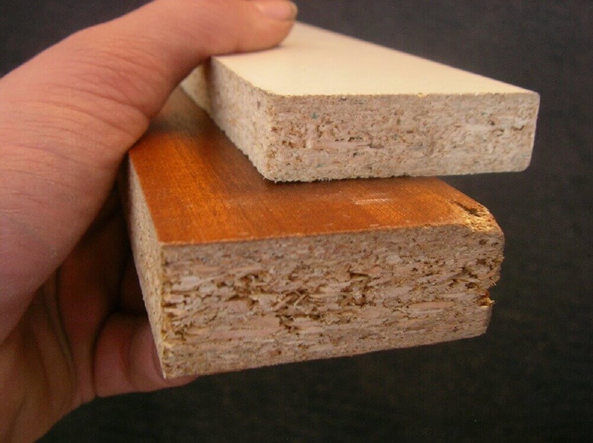
Particle Boards: Particle board, also known as chipboard or low-density fiberboard, is an engineered wood product manufactured from wood chips or jutestick chips and a synthetic resin or other suitable binder, which is pressed and extruded. Particle board is often confused with oriented strand board (also known as flakeboard, waferboard, or chipboard), a different type of fiberboard that uses machined wood flakes and offers more strength.
Particle board is cheaper, denser and more uniform than conventional wood and plywood and is substituted for them when cost is more important than strength and appearance. Particleboard can be made more appealing by painting or the use of wood veneers on visible surfaces. Though it is denser than conventional wood, it is the lightest and weakest type of fiberboard, except for insulation board. Medium-density fibreboard and hardboard, also called high-density fiberboard, are stronger and denser than particleboard. Different grades of particleboard have different densities, with higher density connoting greater strength and greater resistance to failure of screw fasteners.
A significant disadvantage of particleboard is its susceptibility to expansion and discoloration from moisture absorption, particularly when it is not covered with paint or another sealer. Therefore, it is rarely used outdoors or in places where there are high levels of moisture, except in bathrooms, kitchens and laundries, where it is commonly used as an underlayment shielded beneath a moisture resistant continuous sheet of vinyl flooring. Click here to Read more.
 |
How Particle boards are made
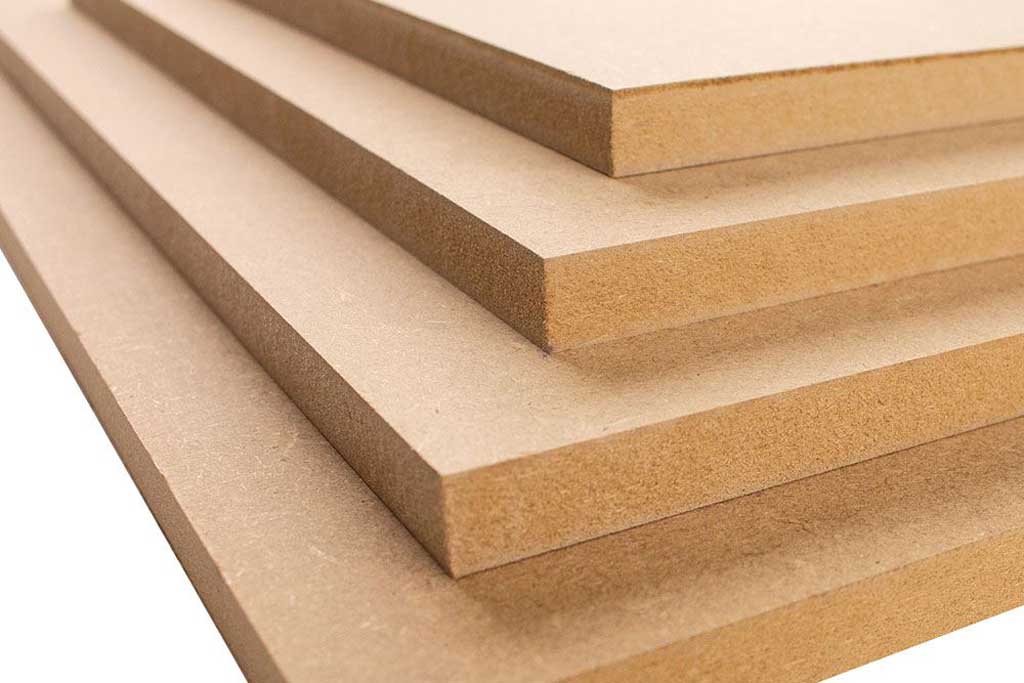
Medium-density fibreboard (MDF): Medium-density fibreboard (MDF) is an engineered wood product made by breaking down hardwood or softwood residuals into wood fibres, often in a defibrator, combining it with wax and a resin binder, g high heat and pressure. MDF is generally denser than plywood. It is made up of separated fibres but can be used as a building material similar in application to plywood. It is stronger and denser than particle board.
Over time, the term "MDF" has become a generic name for any dry-process fibre board. MDF is typically made up of 82% wood fibre, 9% urea-formaldehyde resin glue, 8% water, and 1% paraffin wax.[4] The density is typically between 500 and 1,000 kg/m3^ (31 and 62 lb/cu ft). The range of density and classification as light-, standard-, or high-density board is a misnomer and confusing. The density of the board, when evaluated in relation to the density of the fibre that goes into making the panel, is important. A thick MDF panel at a density of 700-720 kg/m^3 (44-45 lb/cu ft) may be considered as high density in the case of softwood fibre panels, whereas a panel of the same density made of hardwood fibres is not regarded as so. The evolution of the various types of MDF has been driven by differing need for specific applications.
MDF does not contain knots or rings, making it more uniform than natural woods during cutting and in service. However, MDF is not entirely isotropic, since the fibres are pressed tightly together through the sheet. Typical MDF has a hard, flat, smooth surface that makes it ideal for veneering, as no underlying grain is available to telegraph through the thin veneer as with plywood. A so-called "premium" MDF is available that features more uniform density throughout the thickness of the panel. MDF may be glued, doweled, or laminated. Typical fasteners are T-nuts and pan-head machine screws. Smooth-shank nails do not hold well, and neither do fine-pitch screws, especially in the edge. Special screws are available with a coarse thread pitch, but sheet-metal screws also work well. MDF is not susceptible to splitting when screws are installed in the face of the material, but due to the alignment of the wood fibres, may split when screws are installed in the edge of the board without pilot holes. Click here to Read more.
 |
How Medium-density fibreboard (MDF) is made
High-density fiberboard (HDF): Hardboard, also called high-density fiberboard (HDF), is a type of fiberboard, which is an engineered wood product. It is used in furniture and in the construction industry.
HDF is similar to particle board and medium-density fiberboard, but is denser and much stronger and harder because it is made out of exploded wood fibers that have been highly compressed. Consequently, the density of hardboard is 500 kg/m^3 (31 lb/cu ft) or more and is usually about 800-1,040 kg/m^3 (50-65 lb/cu ft). It differs from particle board in that the bonding of the wood fibers requires no additional adhesive, the original lignin in the wood fibers sufficing to bond the hardboard together, although resin is often added.
HDF is produced in either a wet or dry process. The wet process, known as the Mason Method, leaves one smooth side and one textured side, while the dry processed hardboard is smooth on both sides. Masonite is produced using the wet process only. Click here to Read more.
C. Oriented Strand Board (OSB)
Oriented strand board (OSB) is a type of engineered wood similar to particle board, formed by adding adhesives and then compressing layers of wood strands (flakes) in specific orientations. It was invented by Armin Elmendorf in California in 1963. OSB may have a rough and variegated surface with the individual strips of around 2.5 cm x 15 cm (1.0 by 5.9 inches), lying unevenly across each other, and is produced in a variety of types and thicknesses.
OSB is a material with favorable mechanical properties that make it particularly suitable for load-bearing applications in construction. It is now more popular than plywood, commanding 66% of the structural panel market. The most common uses are as sheathing in walls, flooring, and roof decking. For exterior wall applications, panels are available with a radiant-barrier layer laminated to one side; this eases installation and increases energy performance of the building envelope. OSB is also used in furniture production.
Oriented strand board is manufactured in wide mats from cross-oriented layers of thin, rectangular wooden strips compressed and bonded together with wax and synthetic resin adhesives. The adhesive resins types used include: urea-formaldehyde (OSB type 1, nonstructural, nonwaterproof); isocyanate-based glue (or PMDI poly-methylene diphenyl diisocyanate based) in inner regions with melamine-urea-formaldehyde or phenol formaldehyde resin glues at surface (OSB type 2, structural, water resistant on face); phenol formaldehyde resin throughout (OSB types 3 and 4, structural, for use in damp and outside environments).
The layers are created by shredding the wood into strips, which are sifted and then oriented on a belt or wire cauls. The mat is made in a forming line. Wood strips on the external layers are aligned to the panel's strength axis, while internal layers are perpendicular. The number of layers placed is determined partly by the thickness of the panel, but is limited by the equipment installed at the manufacturing site. Individual layers can also vary in thickness to give different finished panel thicknesses (typically, a 15 cm (5.9 in) layer will produce a 15 mm (0.59 in) panel thickness). The mat is placed in a thermal press to compress the flakes and bond them by heat activation and curing of the resin that has been coated on the flakes. Individual panels are then cut from the mats into finished sizes. Most of the world's OSB is made in the United States and Canada in large production facilities. Click here to Read more.
 |
How Oriented Strand Board (OSB) is made
Click here to go back to the top
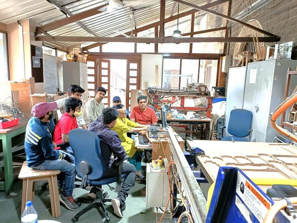
Group Assignment Brief
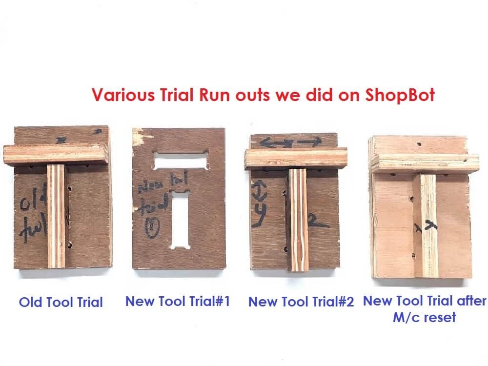
This assignment is about documenting what we learned in Computer-controlled Machining week that includes doing our lab's safety training. After doing this training, we did a few test runouts on shopbot, we checked machine alignment, fixturing requirements, speeds, feeds, materials, and toolpaths generation during test runouts on the machine. We cut a few sample parts with slots and projections (T-shape) to understand the machine accuracy, tolerances and fitments in press-fit joints. Based on the measurements of these test jobs, we concluded on design parameters for the press-fit joints.
Objectives of the Group Assignment:
- To do our lab's safety training
- To do test runout, understand- alignment, fixturing, speeds, feeds, materials, and toolpaths for our machine
 |
 |
|
 |
Click here to read more about our Group Assignment.
Click here to go back to the top
Individual Assignment
 |
|
|
|
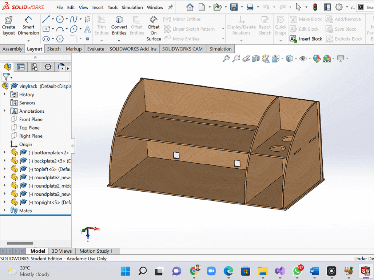
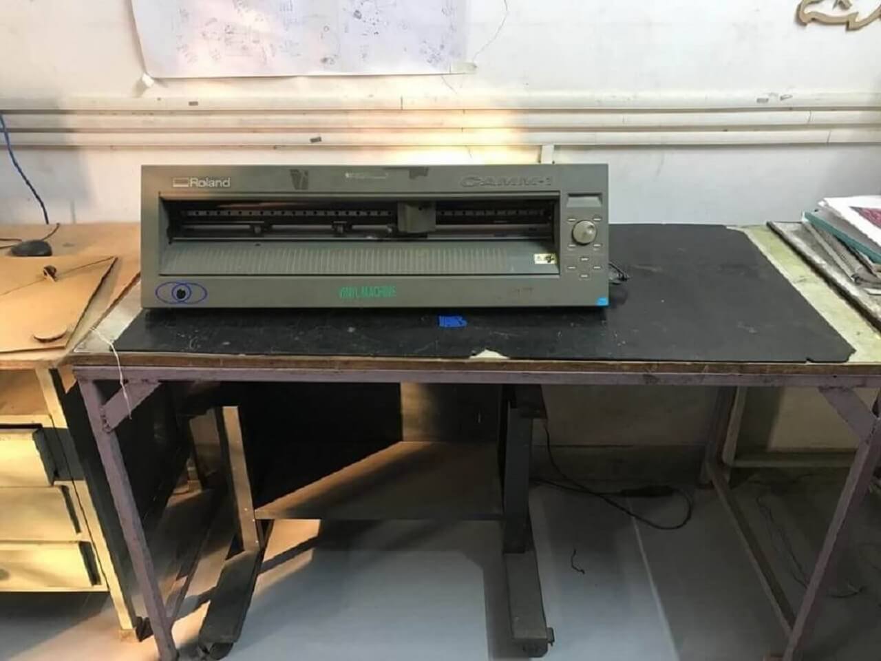
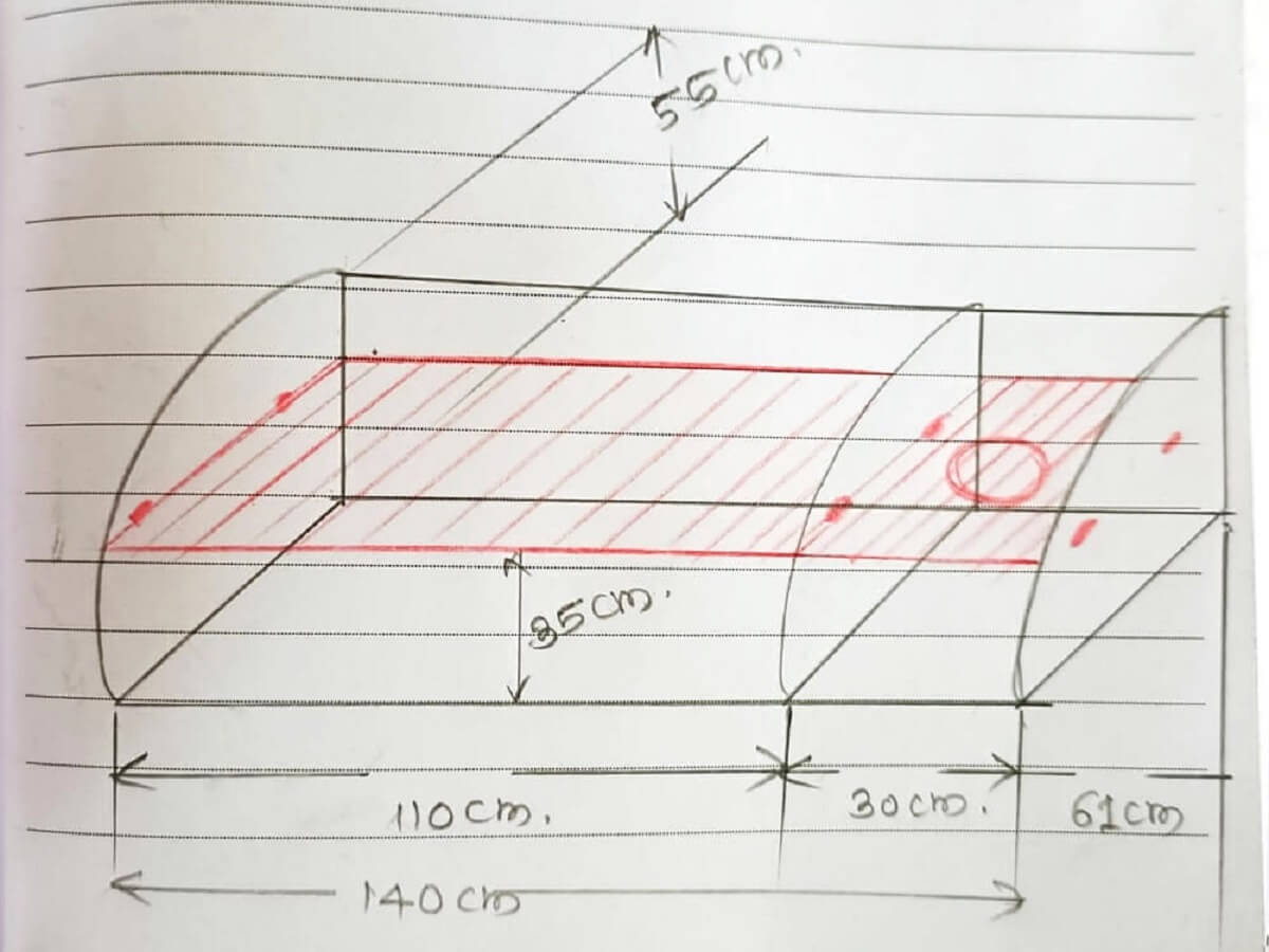
Designing a Rack
Through this assignment, I wanted to make one storage rack for vinyl cutter in our Fab lab at Vigyan Ashram. Following were the steps I followed from sketch to design to mill to assemble.
|
 |
I chose 12 mm commercial plywood sheet for making this rack.
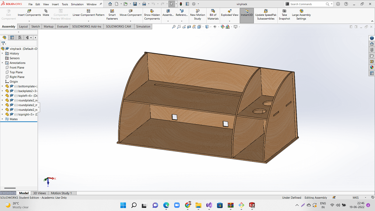 |
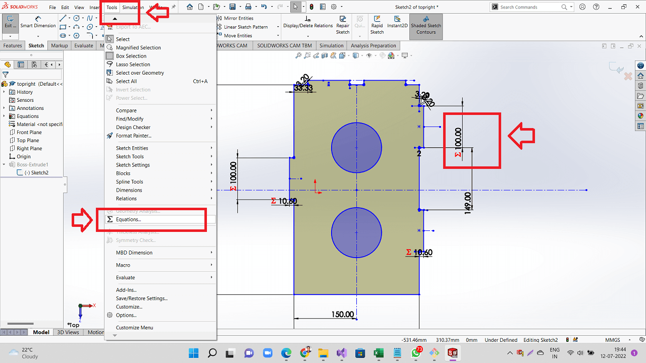
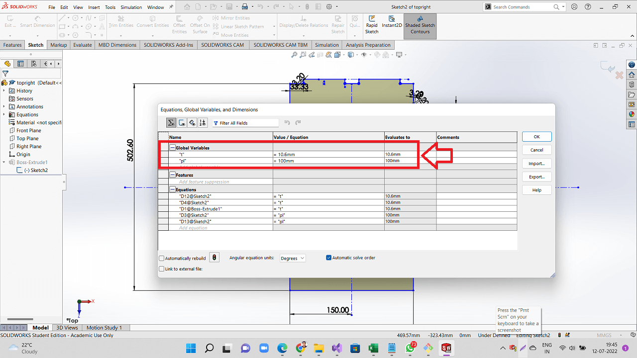
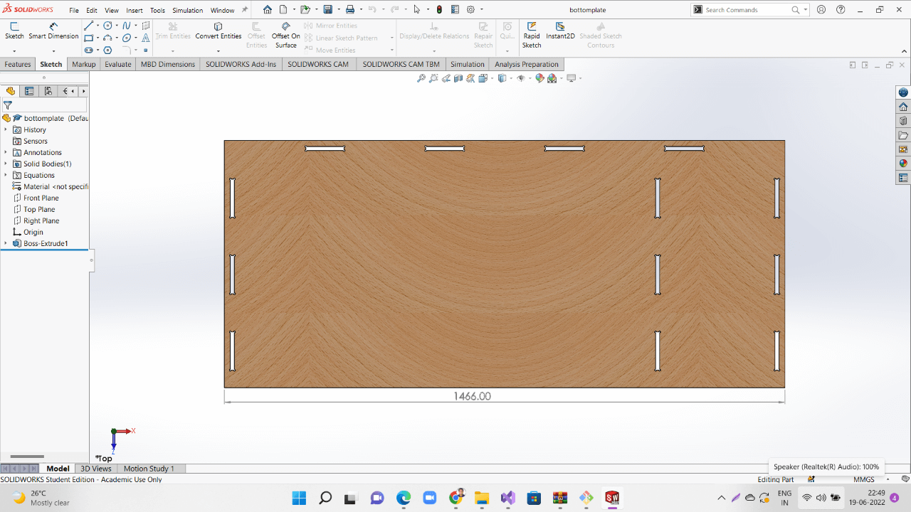
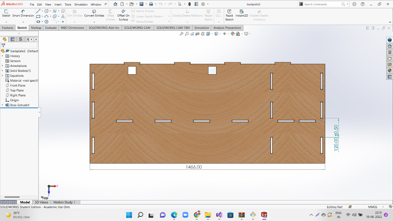
I used parametric modelling for designing slots based on the thickness of the sheet available as shown in both the images below. I applied this all the parts that I have designed to be cut.
 |
 |
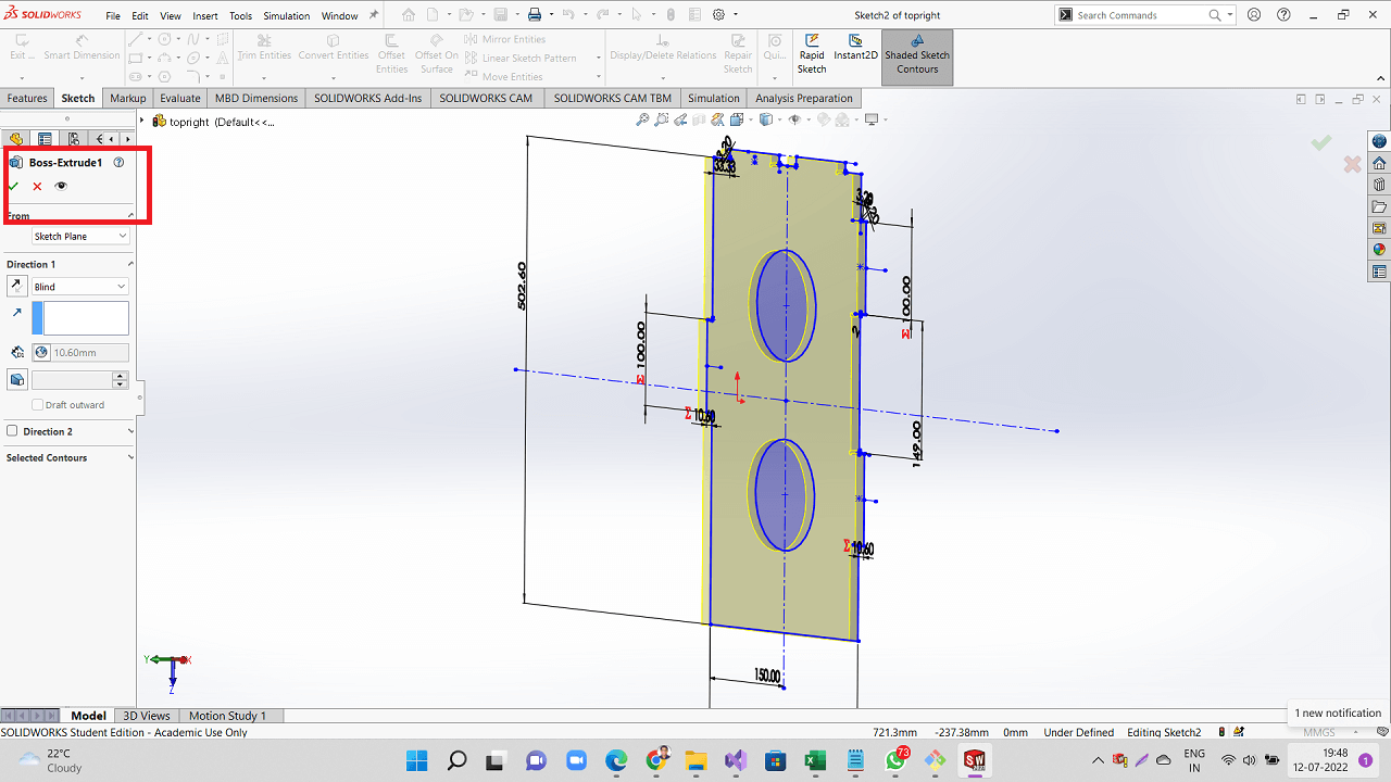
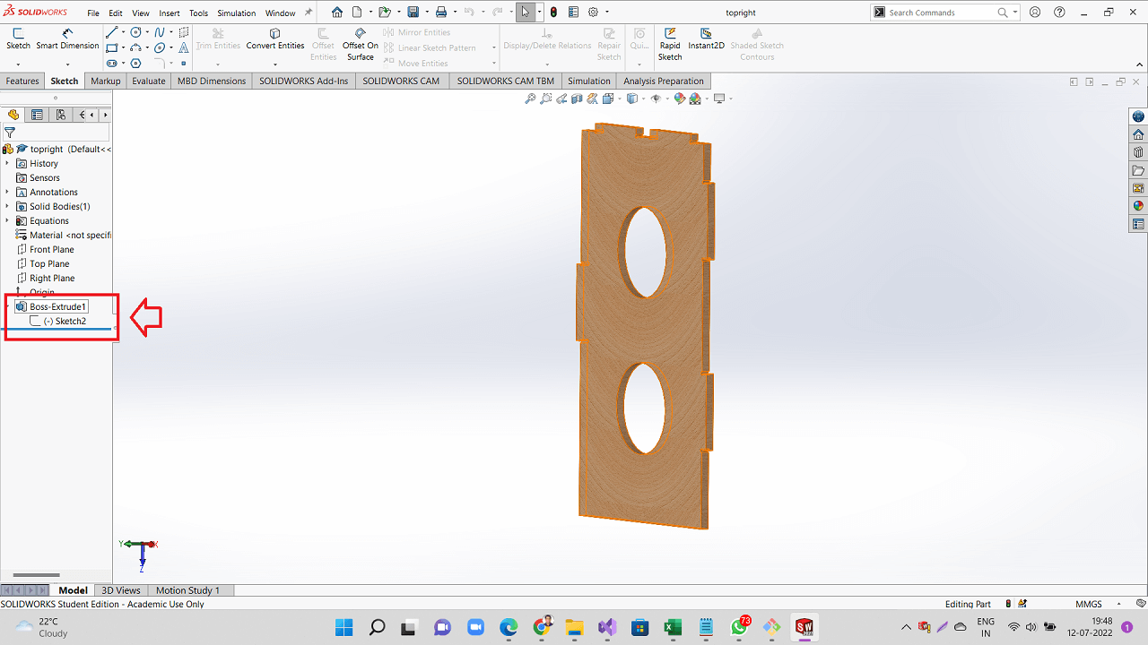
I used features like extrusion to design the parts based on the sheet thickness as shown in both the images below. I applied this all the parts that I have designed to be cut.
 |
 |
 |
 |
 |
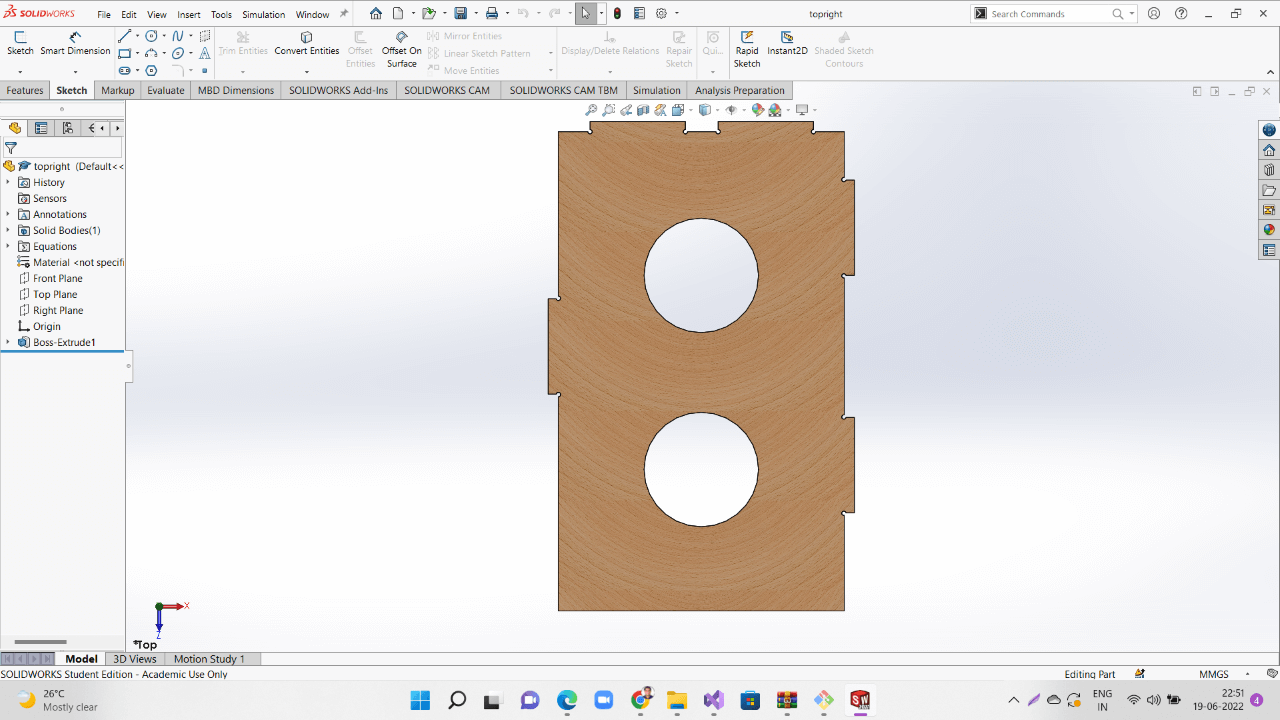 |
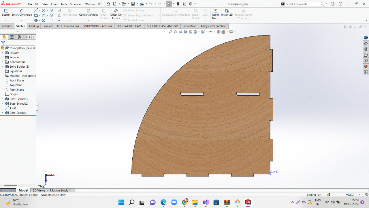 |
 |
After all the parts were designed, I assembled them togehter to see if they are designed correctly.
Creating Toolpaths and Milling
Below are the steps I followed to create toolpaths and subsequently cut parts from the stock on ShopBot. You can refer following documents to learn these steps in detail:
Click here to Download ShopBot Tutorial PDF file.
Click here to go through all of the ShopBot Tutorials.
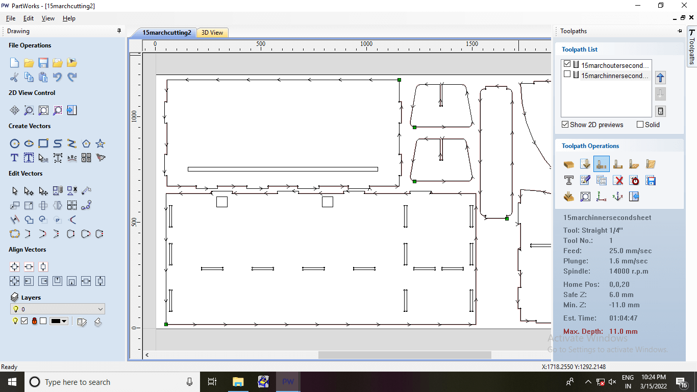
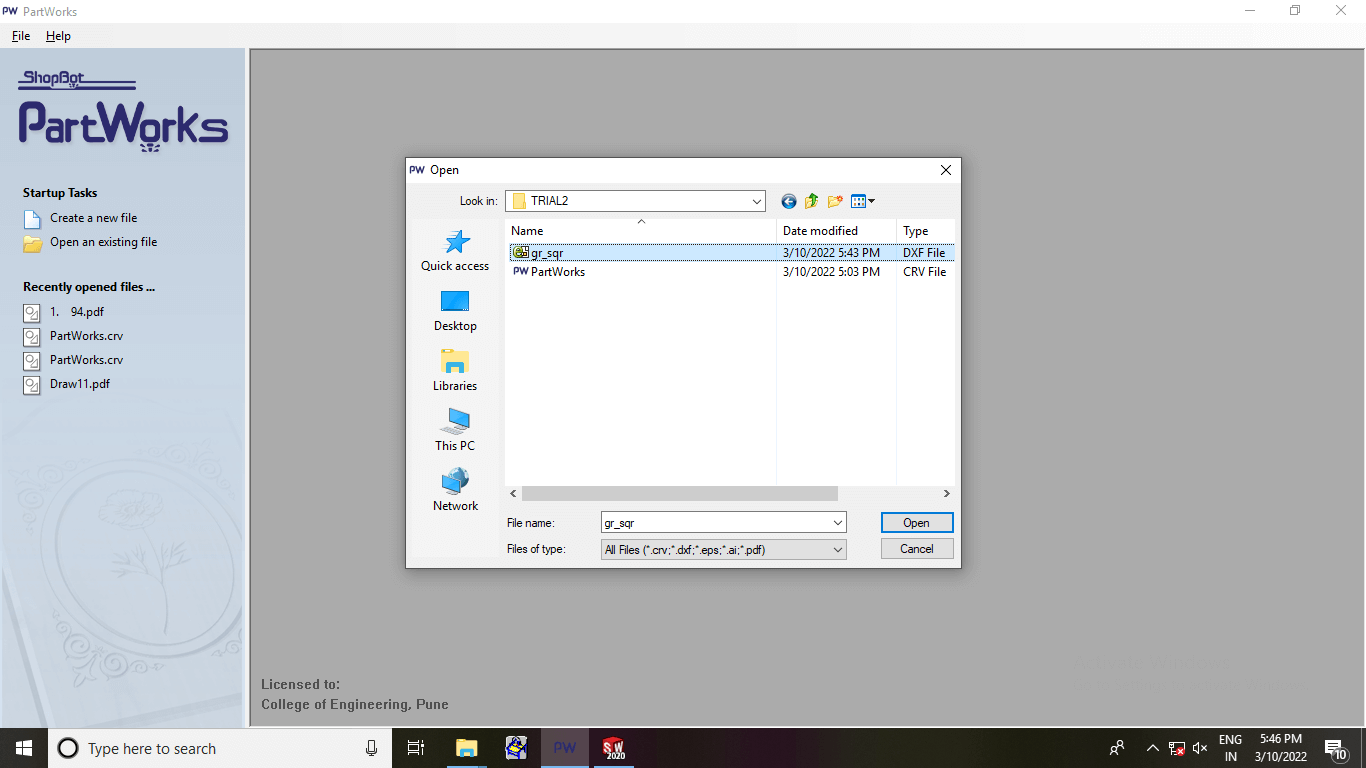
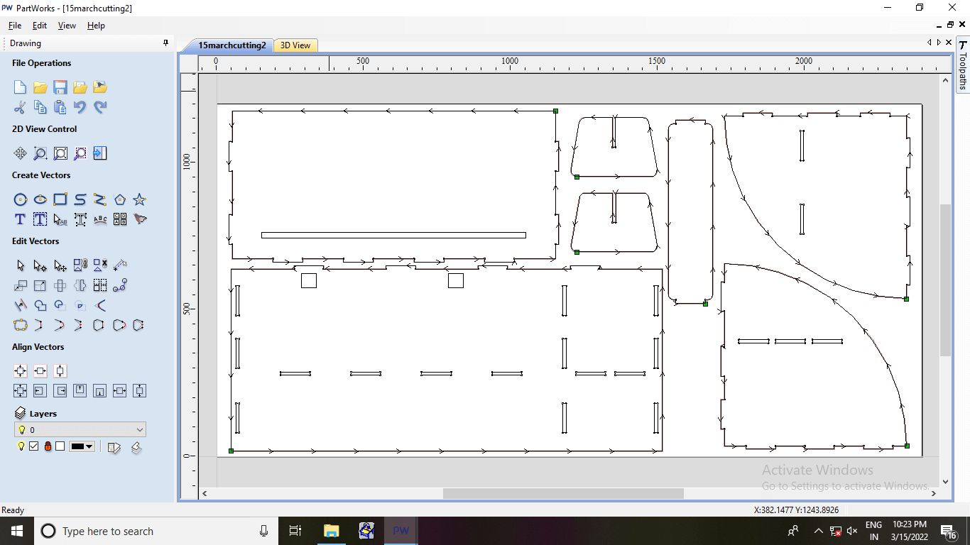
I used PartWorks software (Now, VCarve is being used) to pull part dxf files and create toolpaths.
 |
 |
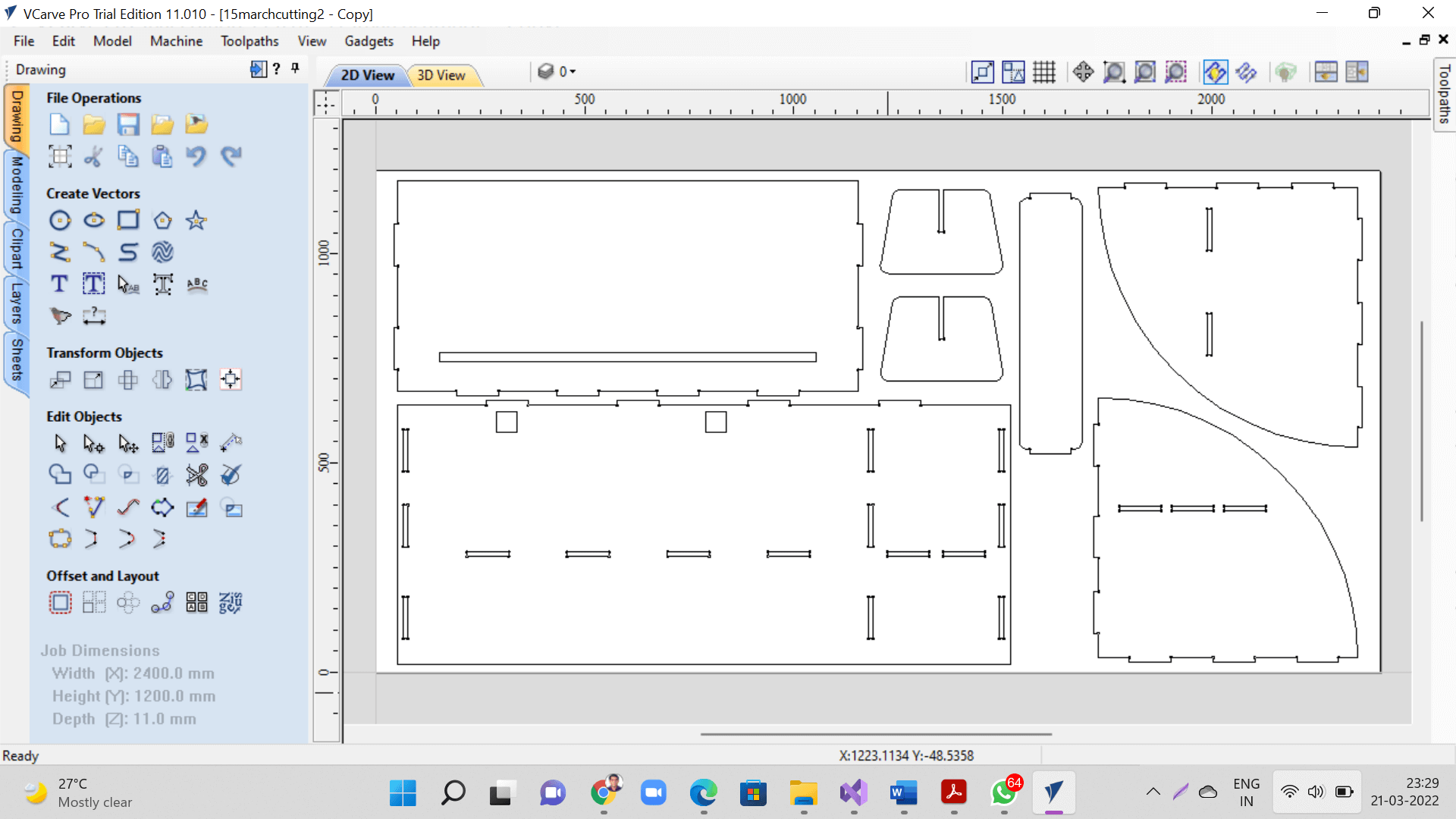
I imported as many part dxf files as possible to create better nesting to maximize the utilization of the sheet. We accomodated parts of other project on these sheets.
 |
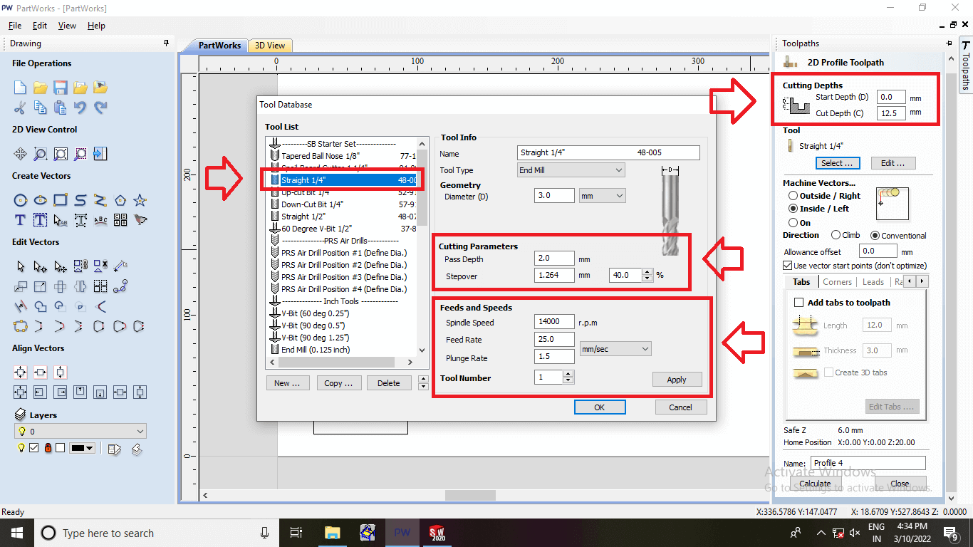
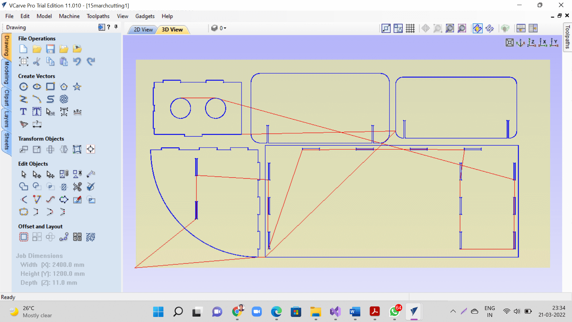
Selected tool, machine parameters like speed, feed, plunge rate, depth of cut, etc. and created toolpaths for inner and outer profiles as shown below.
 |
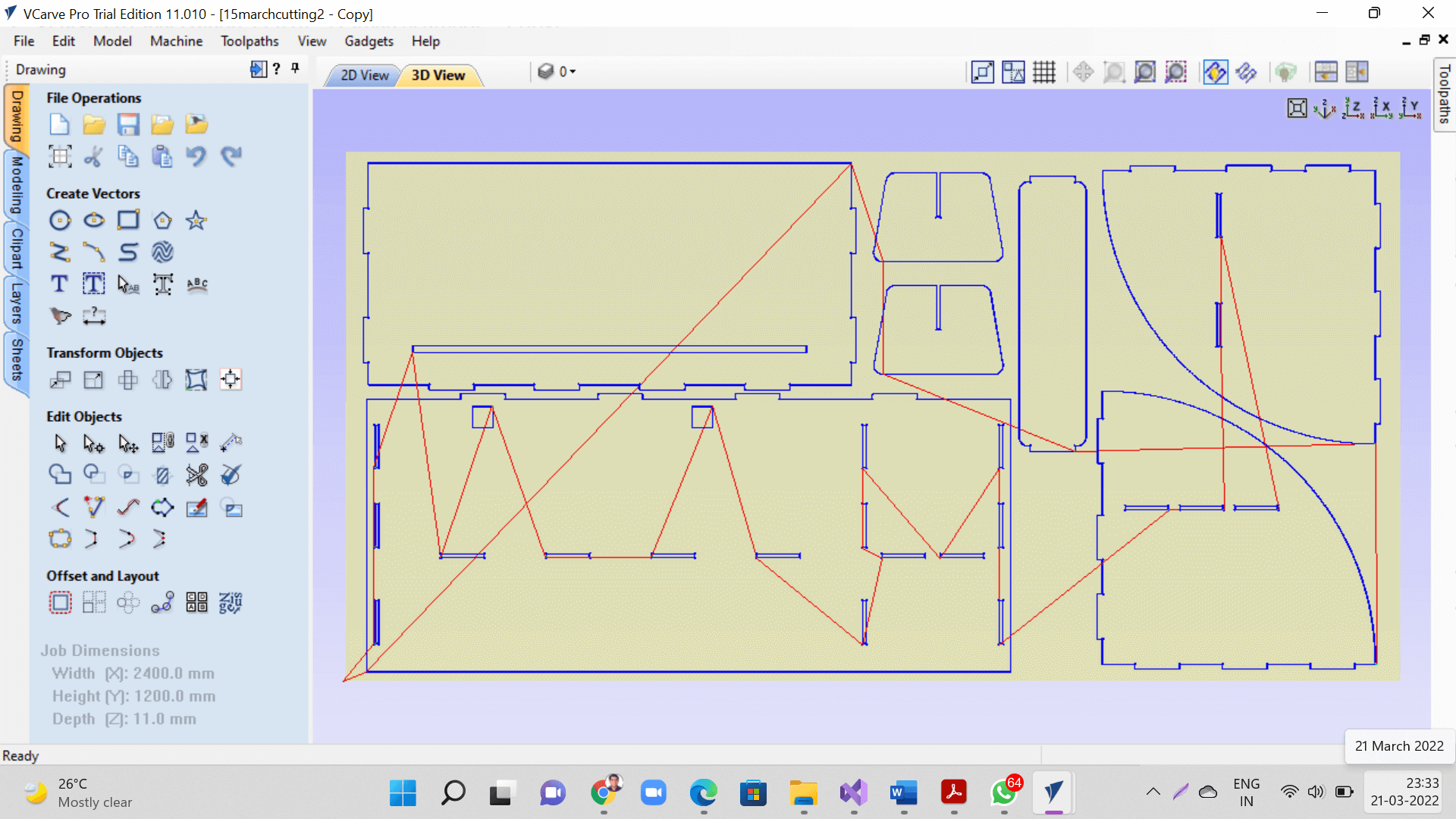
Toolpaths generated for sheet1. We can see 2D and 3D views of toolpaths as shown below. This toolpath will also help us visualize places on our stock, where we can hammer nail to better hold it.
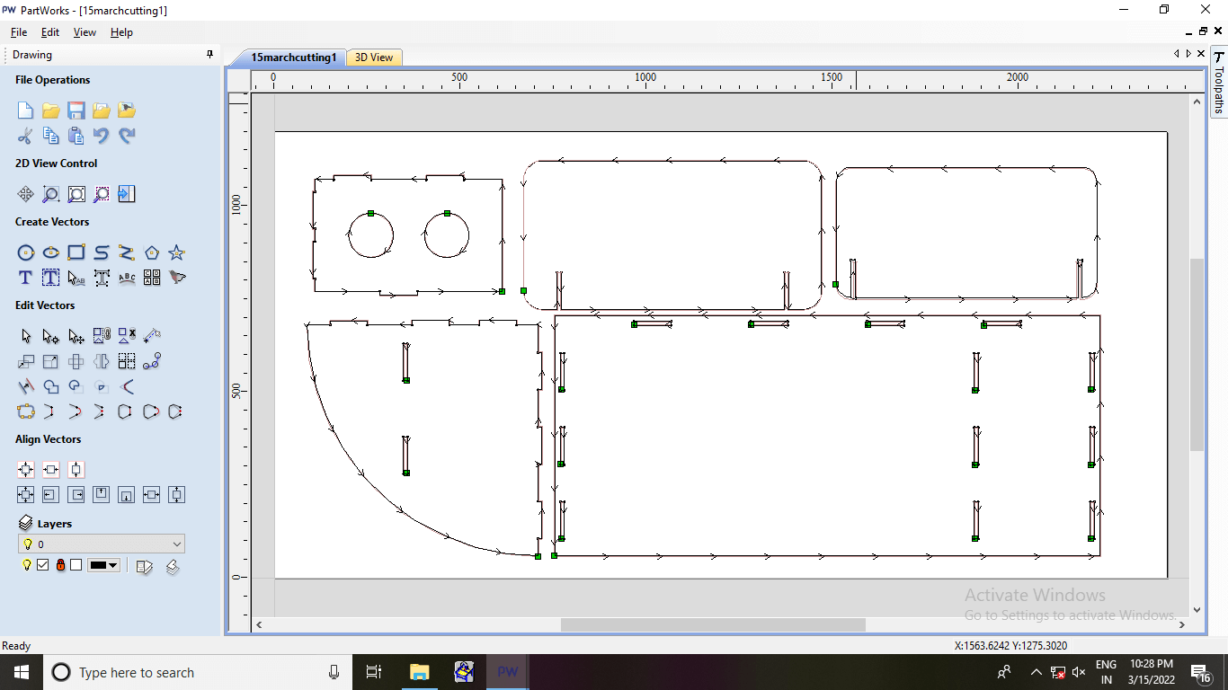 |
 |
Similarly generated toolpaths for sheet2. Here also, we accomodated parts from other project to maximize the stock utilization.
 |
 |
 |
Similarly generated toolpaths for sheet3. So, we effectively used 3 sheets for 2 projects.
 |
 |
 |
Parts Milling and Assembly of the Rack
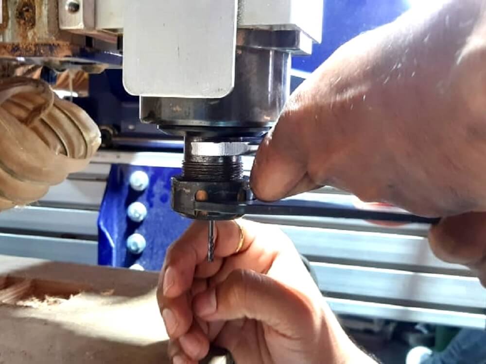
I then changed the tool as per requirement of my job.
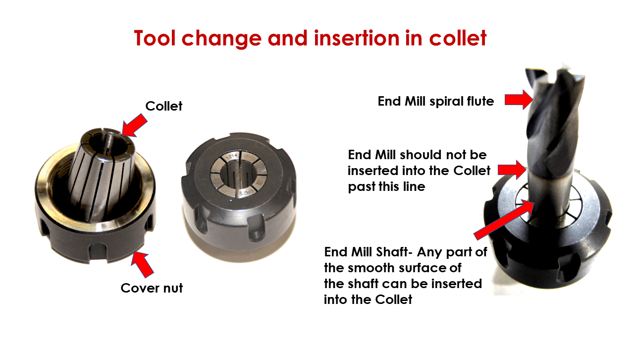 |
Switch ON the machine and make sure the ESTOP buttons are on OFF position.
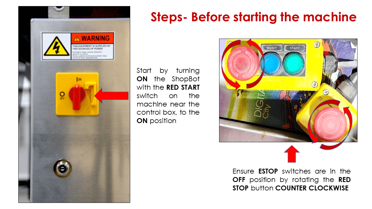 |
I then opened ShopBot console and this dialog prompt appeared on my screen. I need to do following step before moving further.
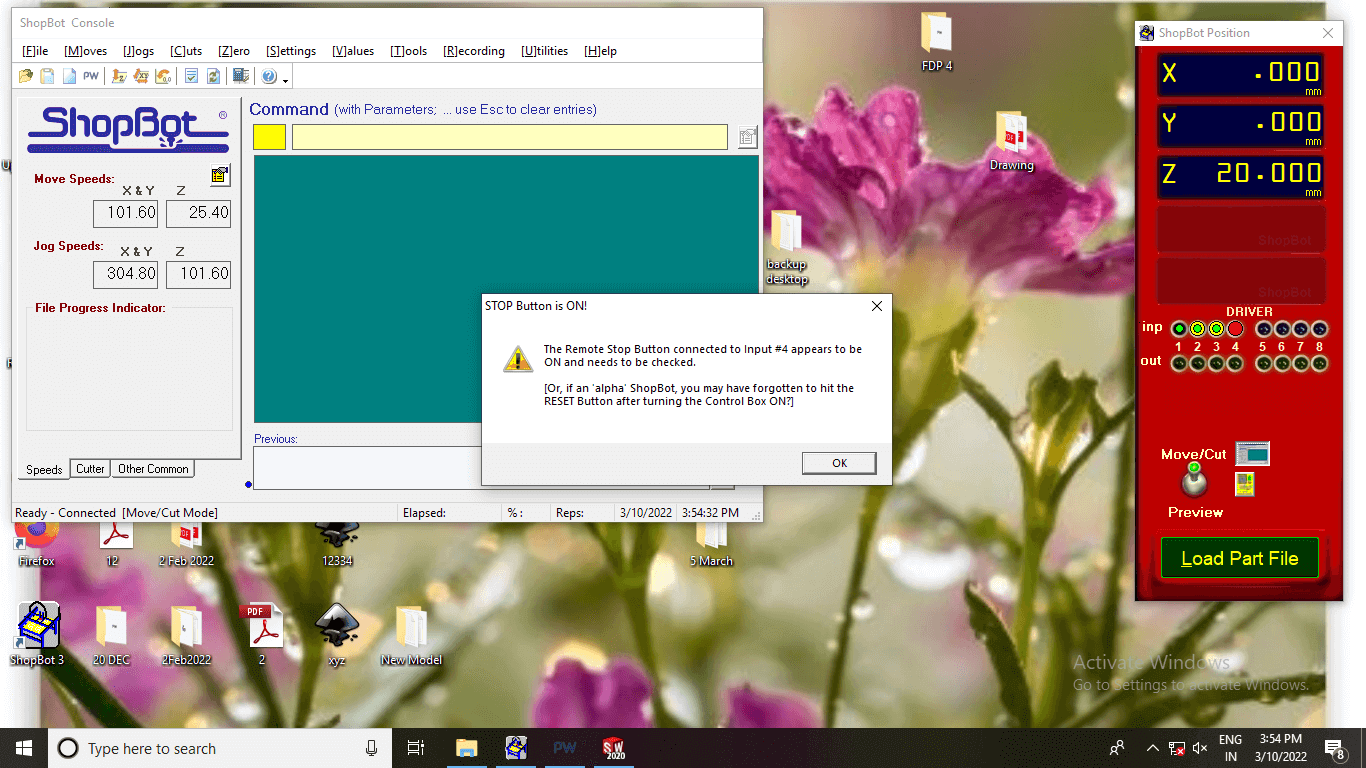 |
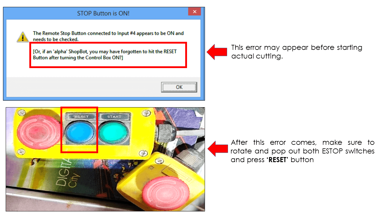 |
I turned the output button #1 ON as shown below.
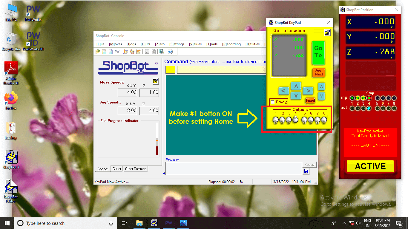 |
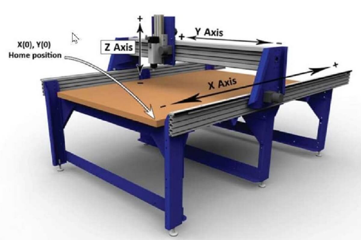
Next, I turned on the spindle by pressing START button on the dongle before I set-up Home position (all three axis on Zero-Zero position) through this window as shown below. I can use keyboard keys like- Page up and Page Down keys to move spindle along Z-axis, use Right, left keys to move spindle along X-axis and use Up, down keys to move spindle along Y-axis as shown below.
I can also use keys on the console to move the spindle to desired position
 |
Now my machine is almost ready to start cutting, I called the toolpath file generated using Partworks in earlier step in to the ShopBot console as shown below.
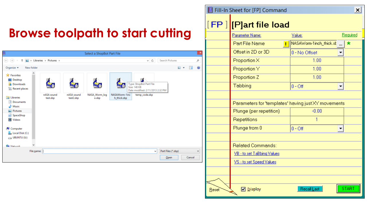 |
DO NOT FORGET to switch ON the dust collector before starting the cutting operation in next step.
|
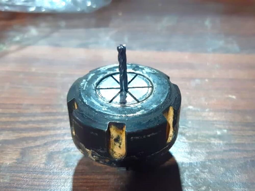
Important STEP: Read the step carefully as I did not follow this step carefully. I started the operation without starting the Spindle ON and it resulted in to tool breakage. Turn the spindle ON by pressing Green START button and ONLY then click OK on the dialog prompt displayed on the screen as shown below.
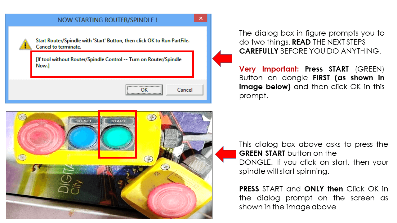 |
The machine started cutting operation. We can see the progress of cutting on the screen as shown below. IMPORTANT: Again, be alert for weird sound, smell and sight. STOP the machine immediately in case anything is wrong. Use STOP button on console as shown below or use Emergency STOP button on the dongle.
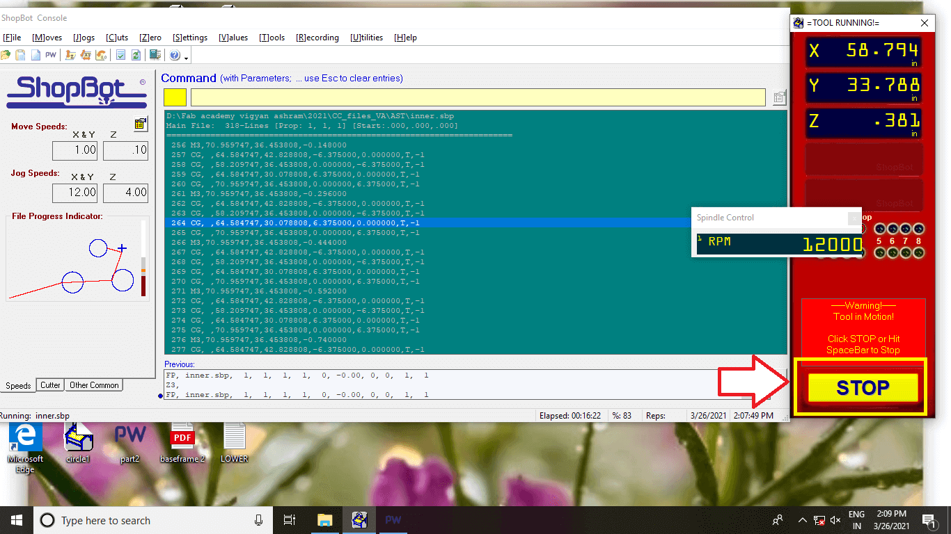 |
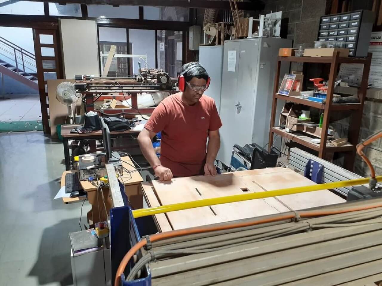
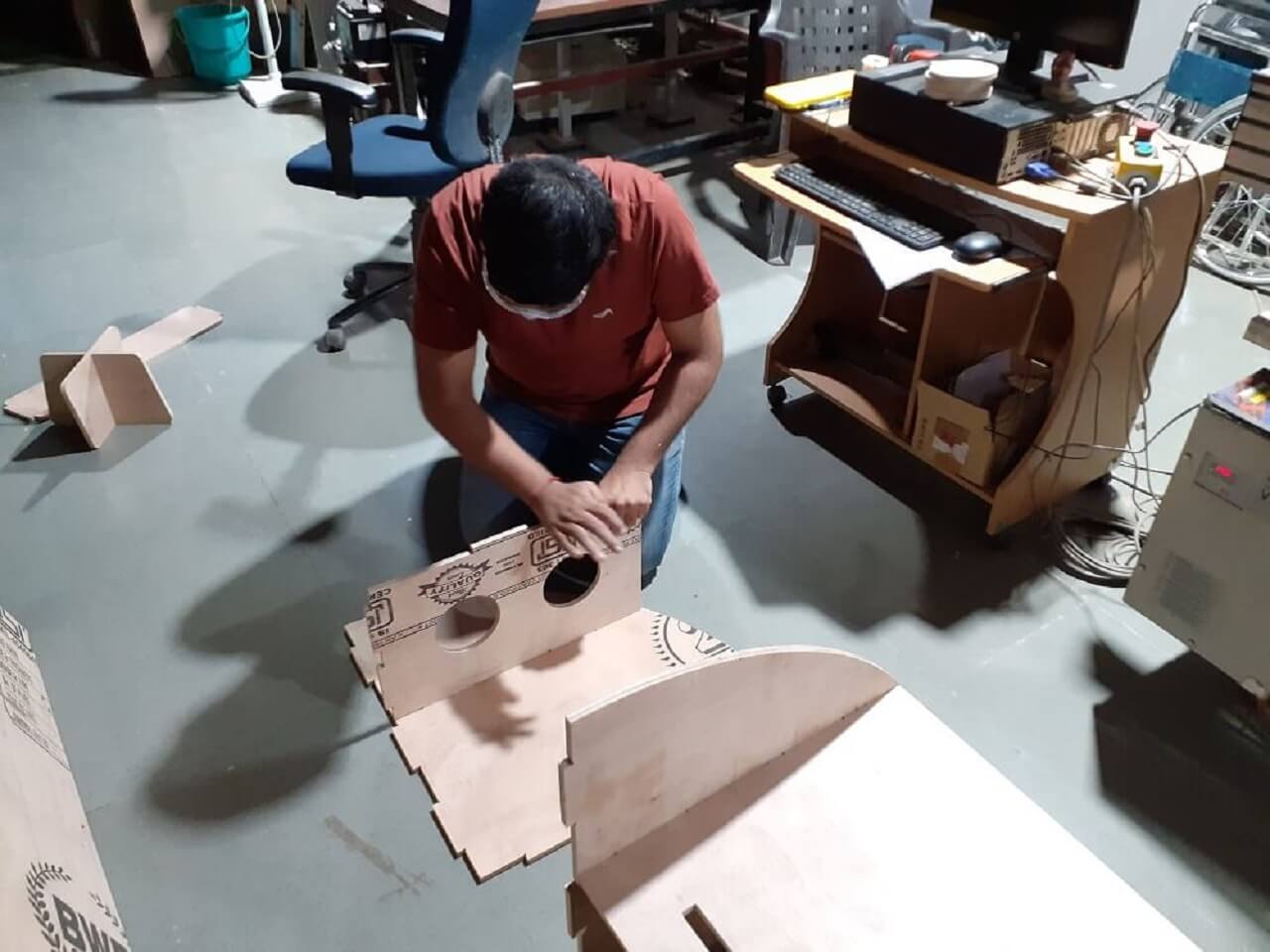
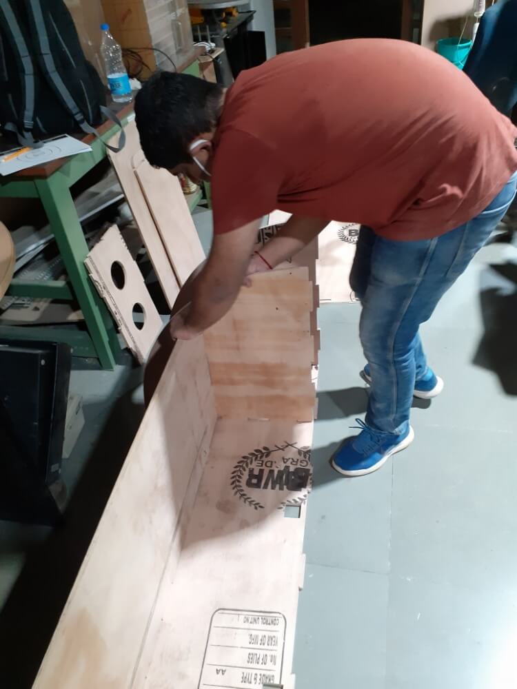
Following are some glimpes of me assemblying the rack.
 |
|
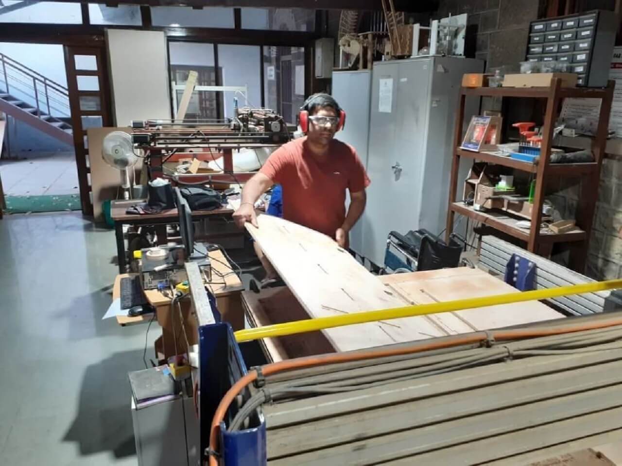 |
I used sandpaper to remove the burr, clean the slots and projections, smoothen the outer edges.
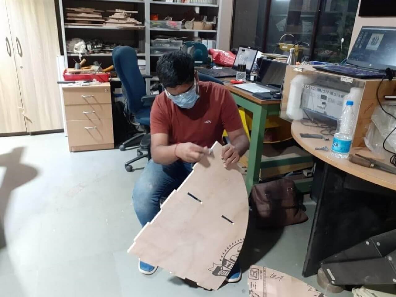 |
I laid down all my parts on the floor the way they will be assembled together and started making sub-assemblies in such way that I can place all the parts together in a sequence.
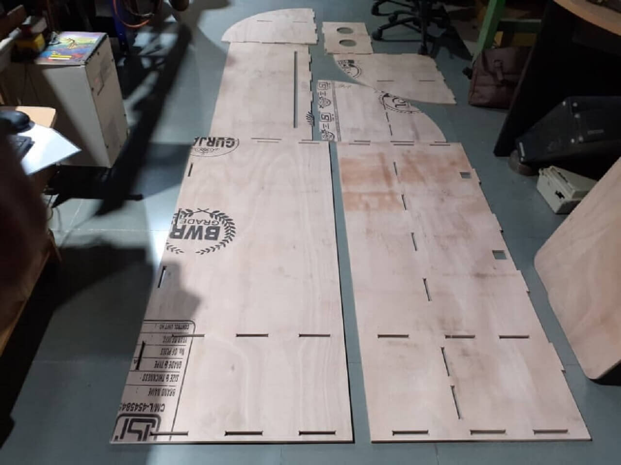 |
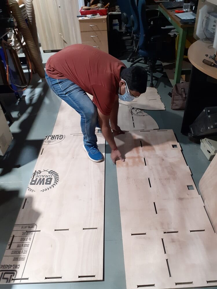 |
 |
|
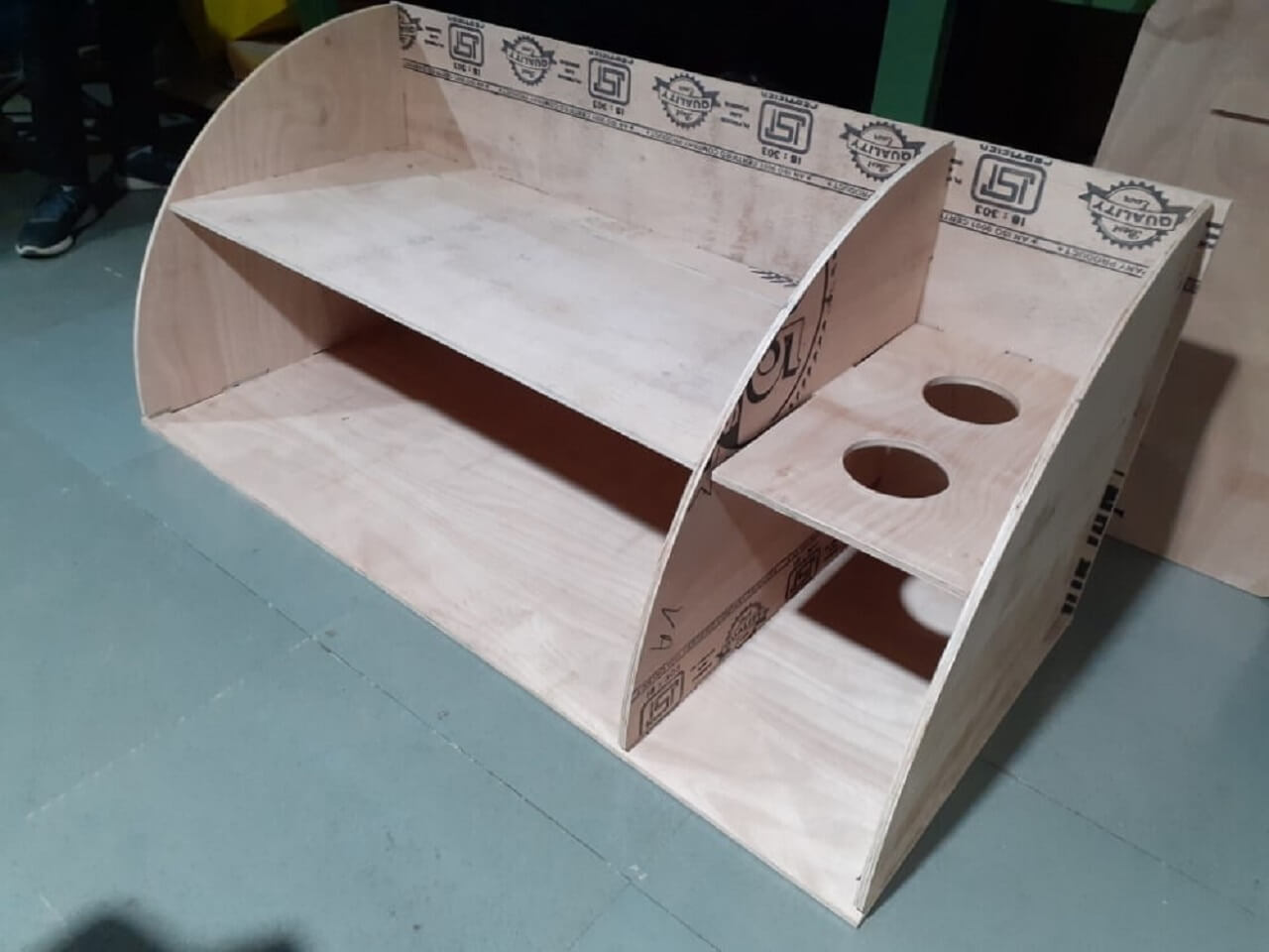
Here is a reward of my 4 days of work in Fab Lab in College of Engineering, Pune (COEP). Great job done by the COEP team as well :)
Final parts that were cut could fit well as per press-fit in to each other as per the assembly design. There were no loose parts and I did not need to tune or do any modifications to the parts, slots, etc. except minor sanding using the sandpaper to remove the sharp burr on the edges on the slot.
|
Following is a way one can disassemble the rack and remove the parts.
Finally, I am again adding the video that I created for entire work on my individual assignment for this week.
Click here to go back to the top
Download Original Files
Click here to download all original files.
Click here to go back to the topWhat went well
In group assignment- We were able conduct multiple test runouts and trials. We could find out error on the Y-axis dimension. However, we resolved that error by resetting the machine and reinstalling the applications. We learned a lot during these two days.
In individual assignment- I was able to complete my design on time and verified assembying and disassemblying process within Solidworks before I generated part dxf files.
What went wrong
In group assignment- We broke one end mill while performing the trials. I was not alert enough to start the spindle before starting the spindle movement for cutting. The machine had errors in Y-axis for 2 consecutive days, it also misbehaved a couple of times. Finally, we resolved it.
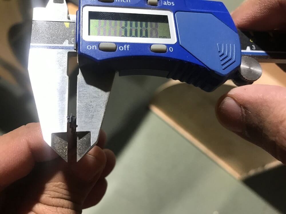
In individual assignment- While cutting my first sheet, we did not nail the sheet in uncut areas, the sheet was raised in the middle of the bed and the tool hit that part of the sheet and broke while it was traveling to the next cutting area. Next time, we hammered nails as a result of this learning. We also inserted the tool inside the collet to reduce it's overhang.
What I would do differently
- I would think of more compact, ergonomic design.
- I would have done more practice on the dry run of the machine.
Learning Outcomes
- I learned how to use Partworks software to create toolpaths for router.
- I learned basics of computer controlled machining (large format machining), tooling and fixturing, and different materials used for routing, their properties, their specific applications, etc.
- I learned how to use ShopBot console.
- I learned to change the end mill on the router.
- I learned the importance of safety requirements and training along with being alert all the time while router is ON.