
Assignment#13: Networking and Communications
This assignment is about documenting what I learned in Networking and Communications week that includes types of networking, communication protocols, their significances in projects, etc. I have documented how I connected my project board through wired and wireless nodes to difference devices. I was able to use bluetooth, LCD and wifi communication in this assignment, which is going to be a part of my final project. I am also documenting what went well, what went wrong, how I would do things differently in next assignment and my learning outcomes.
My Hero shots for this week
1. Connecting bluetooth to collect DS18B20 temperature sensor data and control relay pin through bluetooth.
 |
 |
2. Connecting wifi to publish DS18B20 temperature sensor data to cloud to be displayed over ThingSpeak IoT platform channel.
 |
 |
 |
My Hero videos for this week
1. Bluetooth: Connecting and Reading DS18B20 temperature sensor values and Switching ON/OFF relay through my board
2. Wifi: Connecting DS18B20 temperature sensor and collecting sensor data over thingspeak IoT analytics platform over cloud.
Click here to go back to the top
Basics of Networking and Communication
A network, in the context of electrical engineering and electronics, is a collection of interconnected components. The field of networking and communication includes the analysis, design, implementation, and use of local, wide-area, and mobile networks that link computers together. The Internet itself is a network that makes it feasible for nearly all computers in the world to communicate. A network consists of two or more computers or devices that are linked in order to share resources (such as printers and CDs), exchange files, or allow electronic communications. The devices on a network may be linked through cables, telephone lines, radio waves, satellites, or infrared light beams.
A network is a group of devices connected to share data. Connecting and sharing is commonly referred to as communication. Devices can be components directly in the electrical network such as circuit breakers, sensors associated with the application, communication network infrastructure such as Ethernet switches or controllers automating the system i.e. computers or PLCs.
References: Reference#1, Reference#2, Reference#3
 |
Data communications refers to the transmission of this digital data between two or more computers and a computer network or data network is a telecommunications network that allows computers to exchange data. The physical connection between networked computing devices is established using either cable media or wireless media.
A communication protocol is a system of rules that allows two or more entities of a communications system to transmit information via any kind of variation of a physical quantity. The protocol defines the rules, syntax, semantics and synchronization of communication and possible error recovery methods. Protocols may be implemented by hardware, software, or a combination of both. Communication protocol is a system of rules that allow devices in a network to transmit information. Protocols have well-defined formats, in many cases formal Technical Standards.
References: Reference#1, Reference#2
 |
Parallel Communication
In data transmission, parallel communication is a method of conveying multiple binary digits (bits) simultaneously. It contrasts with serial communication, which conveys only a single bit at a time; this distinction is one way of characterizing a communications link.
The basic difference between a parallel and a serial communication channel is the number of electrical conductors used at the physical layer to convey bits. Parallel communication implies more than one such conductor. For example, an 8-bit parallel channel will convey eight bits (or a byte) simultaneously, whereas a serial channel would convey those same bits sequentially, one at a time. If both channels operated at the same clock speed, the parallel channel would be eight times faster. A parallel channel may have additional conductors for other signals, such as a clock signal to pace the flow of data, a signal to control the direction of data flow, and handshaking signals.
Parallel communication is and always has been widely used within integrated circuits, in peripheral buses, and in memory devices such as RAM. Computer system buses, on the other hand, have evolved over time: parallel communication was commonly used in earlier system buses, whereas serial communications are prevalent in modern computers.
References: Reference#1
 |
Serial Communication
In telecommunication and data transmission, serial communication is the process of sending data one bit at a time, sequentially, over a communication channel or computer bus. This is in contrast to parallel communication, where several bits are sent as a whole, on a link with several parallel channels.
Serial communication is used for all long-haul communication and most computer networks, where the cost of cable and synchronization difficulties make parallel communication impractical. Serial computer buses are becoming more common even at shorter distances, as improved signal integrity and transmission speeds in newer serial technologies have begun to outweigh the parallel bus's advantage of simplicity.
In serial communication, there is no acknowledgement of data. Feedback signal is not received if there is any data loss. Speed of data transfer (Baud rate) is slow. Baud rate is a number of bits per second.
In embedded system, Serial communication is the way of exchanging data using different methods in the form of serial digital binary. Some of the well-known interfaces used for the data exchange are RS-232, RS-485, I2C, SPI etc.
References: Reference#1
 |
Transmission Modes in Serial Communication
In serial communication data is sent in the form of bits i.e. binary pulses and it is well known that, binary one represents the logic HIGH and zero represents the logic LOW. There are several types of serial communication depending on the type of transmission mode and data transfer. The transmission modes are classified as Simplex, Half Duplex and Full Duplex.
Simplex Method: In simplex method either of the medium i.e sender or receiver can be active at a time. So if the sender is transmitting the data then receiver can only accept and vice versa. So simplex method is one-way communication technique. The well-known examples of simplex method are Television and Radio.
Half Duplex Method: In half duplex method both sender and receiver can be active but not at the same time. So if the sender is transmitting then receiver can accept but cannot send and similarly vice versa. The well-known examples of the half duplex is the internet where the user sends a request for a data and the gets it from server.
Full Duplex Method: In full duplex method, both receiver and transmitter can send data to each other at the same time. The well-known example is mobile phone.
References: Reference#1
Apart from this, for appropriate data transmission, the clock plays important role and it is one of the primary source. Malfunction of the clock results in unexpected data transmission even sometimes data loss. So, the clock synchronisation becomes very important when using serial communication. Based on this, serial data can be transferred in two ways-Asynchronous and Synchronous.
Synchronous Serial Communication
Synchronous serial communication describes a serial communication protocol in which "data is sent in a continuous stream at constant rate". Synchronous communication requires that the clocks in the transmitting and receiving devices are synchronized - running at the same rate - so the receiver can sample the signal at the same time intervals used by the transmitter. No start or stop bits are required. For this reason "synchronous communication permits more information to be passed over a circuit per unit time" than asynchronous serial communication. Over time the transmitting and receiving clocks will tend to drift apart, requiring resynchronization.
References: Reference#1
I2C Protocol
I2C communication is the short form for inter-integrated circuits. It is a communication protocol developed by Philips Semiconductors for the transfer of data between a central processor and multiple ICs on the same circuit board using just two common wires. Owing to its simplicity, it is widely adopted for communication between microcontrollers and sensor arrays, displays, IoT devices, EEPROMs etc. This is a type of synchronous serial communication protocol. It means that data bits are transferred one by one at regular intervals of time set by a reference clock line.
Features of I2C Protocol
The following are some of the important features of I2C communication protocol:
- Only two common bus lines (wires) are required to control any device/IC on the I2C network.
- No need of prior agreement on data transfer rate like in UART communication. So the data transfer speed can be adjusted whenever required.
- Simple mechanism for validation of data transferred.
- Uses 7-bit addressing system to target a specific device/IC on the I2C bus.
- I2C networks are easy to scale. New devices can simply be connected to the two common I2C bus lines.
How I2C Protocol works
I2C Bus (Interface wires) consists of just two wires and are named as Serial Clock Line (SCL) and Serial Data Line (SDA). The data to be transferred is sent through the SDA wire and is synchronized with the clock signal from SCL. All the devices/ICs on the I2C network are connected to the same SCL and SDA lines as shown below. Both the lines must be connected to a positive supply using a pull up resistor. SDA (Serial Data): The line for the master and secondary to send and receive data. SCL (Serial Clock): The line that carries the clock signal. I2C is synchronous, so the output of bits is synchronized to the sampling of bits by a clock signal shared between the master and the secondary. The clock signal is always controlled by the master. I2C involves a half duplex communication method (either transmit or receive).
I2C can deliver speed up to 400Kbps and it uses 10 bit or 7 bit addressing system to target a specific device on the i2c bus so it can connect up to 1024 devices. It has limited length communication and is ideal for onboard communication. I2C networks are easy to setup since it uses only two wires and new devices can simply be connected to the two common I2C bus lines. Same like SPI, microcontroller generally have I2C pins to connect any I2C device.
The devices connected to the I2C bus are categorized as either masters or secondary devices. At any instant of time only a single master stays active on the I2C bus. It controls the SCL clock line and decides what operation is to be done on the SDA data line. All the devices that respond to instructions from this master device are secondary devices. For differentiating between multiple secondary devices connected to the same I2C bus, each secondary device is physically assigned a permanent 7-bit address. When a master device wants to transfer data to or from a secondary device, it specifies this particular secondary device address on the SDA line and then proceeds with the transfer. So effectively communication takes place between the master device and a particular secondary device. All the other secondary devices do not respond unless their address is specified by the master device on the SDA line.
 |
 |
SPI Protocol
The Serial Peripheral Interface (SPI) is a synchronous interface which allows several SPI microcontrollers to be interconnected. In SPI, separate wires are required for data and clock line. Also the clock is not included in the data stream and must be furnished as a separate signal.
The SPI may be configured either as master or as a secondary device. The four basic SPI signals (MISO, MOSI, SCK and SS i.e. Chip select, need to declare chip select pin to make it active/inactive to be able to receive/transfer data.), Vcc and Ground are the part of data communication. So it needs 6 wires to send and receive data from secondary device or master. Theoretically, the SPI can have unlimited number of masters and secondary devices. The data communication is configured in SPI registers. The SPI can deliver up to 10Mbps of speed and is ideal for high speed data communication. Multiple SD cards can be connected and read simultaneously (Full duplex), SPI is fast of all communication. RFID also has SPI protocol.
References: Reference#1
 |
Asynchronous Serial Communication
Asynchronous serial communication is a form of serial communication in which the communicating endpoints' interfaces are not continuously synchronized by a common clock signal. Instead of a common synchronization signal, the data stream contains synchronization information in form of start and stop signals, before and after each unit of transmission, respectively. The start signal prepares the receiver for arrival of data and the stop signal resets its state to enable triggering of a new sequence. A common kind of start-stop transmission is ASCII over RS-232, for example for use in teletypewriter operation.
References: Reference#1
UART Communication
UART stands for Universal Asynchronous Receiver/Transmitter. It is not a communication protocol like SPI and I2C, but a physical circuit in a microcontroller, or a stand-alone IC. A UART's main purpose is to transmit and receive serial data.
In UART communication, two UARTs communicate directly with each other. The transmitting UART converts parallel data from a controlling device like a CPU into serial form, transmits it in serial to the receiving UART, which then converts the serial data back into parallel data for the receiving device. Only two wires are needed to transmit data between two UARTs. Data flows from the Tx pin of the transmitting UART to the Rx pin of the receiving UART. UARTs transmit data asynchronously, which means there is no clock signal to synchronize the output of bits from the transmitting UART to the sampling of bits by the receiving UART. Instead of a clock signal, the transmitting UART adds start and stop bits to the data packet being transferred. These bits define the beginning and end of the data packet so the receiving UART knows when to start reading the bits.
References: Reference#1
 |
More details on serial communication protocols
Click here to go back to the topGroup Assignment Brief
This assignment is about documenting what we learned in Networking and communication week that includes understanding different communication protocols, networking types and how to communicate between two boards by sending a message between two projects.
Objectives of the Group Assignment:
- Send a message between two projects
For the purpose of this group assignment, we established communication between two of our project boards having ESP32-Wroom microcontroller and were able to send messages between the boards as shown below.
 |
Click here to see/copy program for communication between 2 ESP32 boards or download sketch from the cloud screen below.
 |
 |
 |
Click here to read more about our Group Assignment.
Click here to go back to the top
Individual Assignment
Objectives of Individual Assignment:
- Design, build, and connect wired or wireless node(s) with network or bus addresses
Understanding communication Protocols for peripherals on my board
It has been 2 weeks now that I have connected input and output devices to my project board. However, through this assignment, I wanted to understand the way these peripherals communicate with microcontroller (ESP32) on my project board.
I am using DS18B20 temperature sensor and MQ2 gas sensor as input devices and relay, LCD screen as output devices for my board. I went through communication protocols for each one of them as below.
1. Communication Protocol for DS18B20 sensor:
The DS18B20 Digital Thermometer provides 9 to 12-bit (configurable) temperature readings which indicate the temperature of the device. Information is sent to/from the DS18B20 over a 1-Wire interface, so that only one wire (and ground) needs to be connected from a central microprocessor to a DS18B20. Power for reading, writing, and performing temperature conversions can be derived from the data line itself with no need for an external power source.
Because each DS18B20 contains a unique silicon serial number, multiple DS18B20s can exist on the same 1-Wire bus. This allows for placing temperature sensors in many different places. Applications where this feature is useful include HVAC environmental controls, sensing temperatures inside buildings, equipment or machinery, and process monitoring and control.
Following is a block diagram of DS18B20. The 64-bit ROM stores the device's unique serial code. The scratchpad memory contains the 2-byte temperature register that stores the digital output from the temperature sensor. In addition, the scratchpad provides access to the 1-byte upper and lower alarm trigger registers (TH and TL) and the 1-byte configuration register. The configuration register allows the user to set the resolution of the temperature-to-digital conversion to 9, 10, 11, or 12 bits.
 |
The DS18B20 uses Maxim's exclusive 1-Wire bus protocol that implements bus communication using one control signal. The control line requires a weak pullup resistor since all devices are linked to the bus via a 3-state or open-drain port (the DQ pin in the case of the DS18B20). In this bus system, the microprocessor (the master device) identifies and addresses devices on the bus using each device's unique 64-bit code. Because each device has a unique code, the number of devices that can be addressed on one bus is virtually unlimited.
With the 1-Wire port, the memory and control functions will not be available before the ROM function protocol has been established. The master must first provide one of five ROM function commands: 1) Read ROM, 2) Match ROM, 3) Search ROM, 4) Skip ROM, or 5) Alarm Search. These commands operate on the 64-bit lasered ROM portion of each device and can single out a specific device if many are present on the 1-Wire line as well as indicate to the bus master how many and what types of devices are present. After a ROM function sequence has been successfully executed, the memory and control functions are accessible and the master may then provide any one of the six memory and control function commands.
Connecting and Powering DS18B20 sensor:
The DS18B20 can be powered by an external supply on the VDD pin, or it can operate in "parasite power" mode, which allows the DS18B20 to function without a local external supply. Parasite power is very useful for applications that require remote temperature sensing or that are very space constrained.
The DS18B20 can also be powered by the conventional method of connecting an external power supply to the VDD pin, as shown below
 |
References: Reference#1- Maxim Integrated's Data Sheet for DS18B20, Reference#2- Sparkfun's Data Sheet for DS18B20
2. Using in-built Bluetooth in ESP32 on my project board
Bluetooth, a wireless communication technology, which is popular for quite a long time. Being operated in the unlicensed 2.4 GHz ISM (Industrial, Scientific and Medical) frequency band, Bluetooth is a short range wireless communication technology with range up to 100 m.
ESP32 SoC integrates both the Bluetooth Link Controller (or Link Manager) and the Baseband into its silicon. Physically, only an external antenna is needed for proper Bluetooth Communication. Since both Wi-Fi and Bluetooth operate at the same 2.4 GHz ISM frequency, the Wi-Fi Radio and the Bluetooth Radio share the same antenna in ESP32. If you take a look at the pinout of ESP32 SoC, there is only one pin for connecting to antenna (LNA_IN).
ESP32 supports both the Classic Bluetooth (Classic BT) and Bluetooth Low Energy (BLE) that can be configured with BLUEDROID Bluetooth Stack. ESP32 Bluetooth supports three types of Host Controller Interface (HCI): UART, SPI and VHCI (Virtual HCI) interfaces (only one can used at a time and UART is the default).
Classic Bluetooth and BLE or Bluetooth Low Energy in ESP32
The Classic Bluetooth also known as Bluetooth Base Rate / Enhanced Data Rate, is the original point-to-point network topology designed for one-to-one wireless communication between a master and a secondary device. Even though multiple secondary devices can be connected to a single master, only one secondary device can be actively communicating with the master. Our Bluetooth keyboards and mouse work with Classic Bluetooth technology. Another simple example is file transfer between two devices (like two mobile phone or a laptop and a mobile phone) over Bluetooth is based on Classic Bluetooth functionality.
BLE or Bluetooth Low Energy on the other hand, as the name suggests, is designed for low power operation and developed with IoT applications as the main target. Bluetooth Specification 4.0 added BLE functionality and is mainly used in battery operated devices like watches, audio devices, health trackers, fitness monitors and data beacons.
 |
ESP32 Classic Bluetooth Serial Communication
ESP32, which already has a Bluetooth Controller, operates on serial communication between the main Xtensa Processor and the Bluetooth Controller. What this means is that after receiving data from a Bluetooth device wirelessly, the Bluetooth controller in ESP32 transfers this data to ESP32's Processor over serial communication. Similarly, in order to send data over Bluetooth, the Processor of ESP32 transmits data to the Bluetooth Controller using the serial interface.
A dedicated 'BluetoothSerial' library is required to transmit and receive data. Some of the frequently used functions offered by BluetoothSerial library are:
- begin()
- available()
- write()
- read()
References and Credits for ESP32 Bluetooth documentation so far: Click here
3. Using in-built wifi in ESP32 on my project board
ESP32 implements TCP/IP, full 802.11 b/g/n/e/i WLAN MAC protocol, and Wi-Fi Direct specification. This means ESP 32 can speak to most of the WiFi Routers out there when used in station(client) mode. Also it is able to create an Access point with full 802.11 b/g/n/e/i.
The ESP32 board can act as Wi-Fi Station, Access Point or both. When the ESP32 is set as a Wi-Fi station, it can connect to other networks (like router). In this scenario, the router assigns a unique IP address to the ESP board. We can communicate with the ESP using other devices (stations) that are also connected to the same network by referring to the ESP unique IP address. The router is connected to the internet, so we can request information from the internet using the ESP32 board like data from APIs (weather data, for example), publish data to online platforms, use icons and images from the internet or include JavaScript libraries to build web server pages.
 |
When we set our ESP32 board as an access point, we can be connected using any device with Wi-Fi capabilities without connecting to the router. When we set the ESP32 as an access point, we create its own Wi-Fi network, and nearby Wi-Fi devices (stations) can connect to it, like our smartphone or computer. So, we don't need to be connected to a router to control it. This can be also useful if we want to have several ESP32 devices talking to each other without the need for a router.
 |
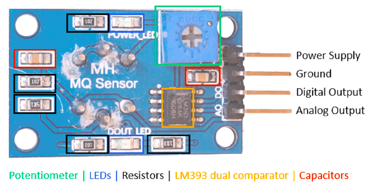
4. Communication Protocol for MQ2 gas sensor module:
MQ2 gas sensor module has 4 pins as we have seen in my last assignment. I am again sharing the pinout below along with pin description. The serial communication for data transfer happen through Analog and Digital pins of MQ2 sensor. The other two pins are Vcc and GND to supply power to the sensor.
 |
 |
5. Communication Protocol for 16x2 LCD Screen:
I have attached an I2C Module to the 16x2 LCD. It works as an intermediator between the LCD and MCU (ESP32 in my case). Following is I2C serial Interface Adapter. It is also known as I2C Module. It has a total of 20 male pins. 16 pins are facing to rear side and 4 pins facing towards the front side. The 16 pins are to connect to 16x2 LCD. The 2 pins out of 4 pins are SDA and SCL. SDA is the serial data pin and SCL is the clock pin. The rest 2 pins for power supply (Vcc and ground). Before we start using the LCD, we need to know the addresses of I2C devices. Every I2C device which are attached to the board have an address. We need to know this address to communicate with that particular device.
 |
Connecting wired and wireless node(s) with network or bus addresses
1. Connecting Bluetooth to control relay and collect temperature values:
I connected DS18B20 temperature sensor and a relay to control exhaust fan. I wanted to control relay through bluetooth and also collect temperature data from DS18B20.
|
Click here to see/copy program for communication through bluetooth or download sketch from the cloud screen below.
Code explaination:
I first included the necessary libraries at the beginning of the code, e.g. The BluetoothSerial library for Bluetooth, and the OneWire and DallasTemperature for the DS18B20 temperature sensor.
 |
Then, I created a BluetoothSerial instance called SerialBT.
 |
After that I created a variable called RelayPin to define the GPIO I want to control. In my board, relay is connected to the GPIO26.
 |
I defined the DS18B20 sensor pin and created objects to make it work. The temperature sensor is connected to GPIO12 on my board.
 |
Later, I created an empty string called message to store the received messages as shown below. After that, I created a char variable called incomingChar to save the characters coming via Bluetooth Serial. The temperatureString variable is defined the temperature readings to be sent via Bluetooth as shown below.
 |
Auxiliar timer variables to send readings every 10 seconds are created as shown below.
 |
In the setup(), set the RelayPin as an output. Then, to initialize the ESP32 as a bluetooth device with the "ESP32" name.
 |
In the loop(), temperature readings are sent, received messages are read and actions are executed accordingly. The following part of the code, checks if 10 seconds have passed since the last reading. If it is time to send a new reading, we get the latest temperature and save it in Celsius and Fahrenheit in the temperatureString variable as shown below. Then, to send the temperatureString via bluetooth, I used SerialBT.println().
 |
The if statement in the code reads incoming messages. When we receive messages via serial, we receive a character at a time. We know that the message ended, when we receive \n. So, we check if there is data available in the Bluetooth serial port. If there is, we will save the characters in the incomingChar variable as shown below.
 |
If the incomingChar is different than \n, we will concatenate that char character to our message. When we are finished reading the characters, we clear the message variable. Otherwise all received messages would be appended to each other.
 |
After that, we have two if statements to check the content of the message. If the message is Relay_on, the Relay turns on. If the message is Relay_off, the Relay turns off.
 |
Connecting and Reading DS18B20 temperature sensor values and Switching ON/OFF relay through my board
Once this code was uploaded, I opened the Serial Monitor. When I received the message "The device started, now you can pair it with bluetooth!", I went to my smartphone and connected it with my board's ESP32 as seen in the video below.
|
2. Connecting wifi to collect Temperature sensor values and publishing through Thingspeak:
In my final project, I am connecting DS18B20 temperature sensor and a relay to my board. Through this assignment, I wanted to collect temperature readings by the sensor and control relay connected to the exhaust fan. I also wanted to publish these readings over thingspeak IoT analytics platform over cloud.
|
Click here to see/copy program for communication through wifi or download sketch from the cloud screen below.
Code explaination:
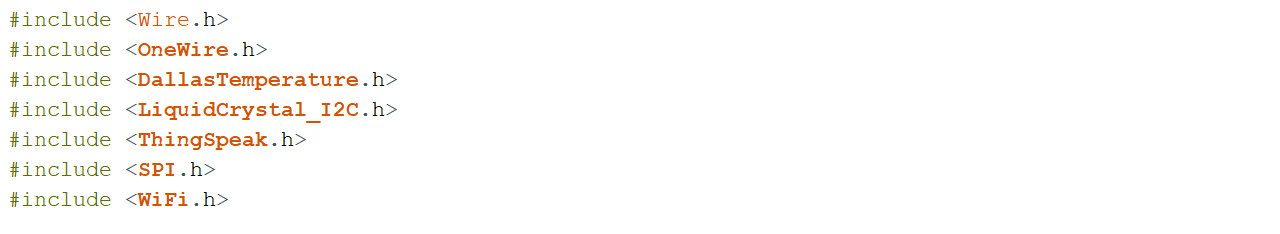
I first included the necessary libraries at the beginning of the code, e.g. wire library for I2C device communication (LCD in my case), the OneWire and DallasTemperature for the DS18B20 temperature sensor, LiquidCrystal_I2C for I2C serial interface adapter used with 16x2 LCD screen, ThingSpeak library for communicating data to ThingSpeak cloud and wifi library for using wifi.
 |
Then, I declared a LiquidCrystal 12C object with 12C address, the number of columns, the number of rows (16 columns and 2 rows in my case)
 |
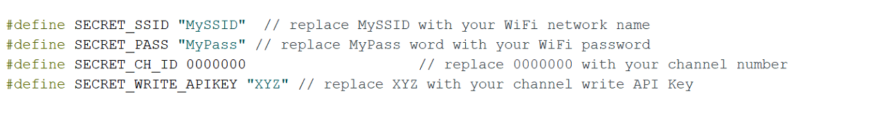
I defined SSID and password for my wifi network along with Channel ID and Secret Write API key for my ThingSpeak IoT channel.
 |
After that, I created two char variable called char ssid[] and char pass[] to save the SSID and password.
 |
Through WiFiClient, I created a client that can connect to a specified internet IP address and port as defined in client. int keyIndex = 0; is network key Index number (needed only for WEP).
 |
I also created one unsigned long variables (extended size variables) for storing my Thingspeak Channel ID along with const char* to declare Write API key for my channel.
 |
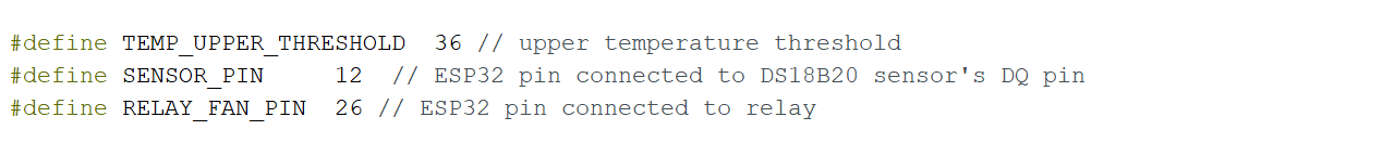
I defined upper threshold temperature for my project above, which the exhaust fans will be switched ON. I defined GPIO 12 for onewire bus for DS18B20 sensor and GPIO 26 for Relay pin.
 |
After defining the DS18B20 sensor pin I created objects OneWire and DallaTemperature to make it work.
 |
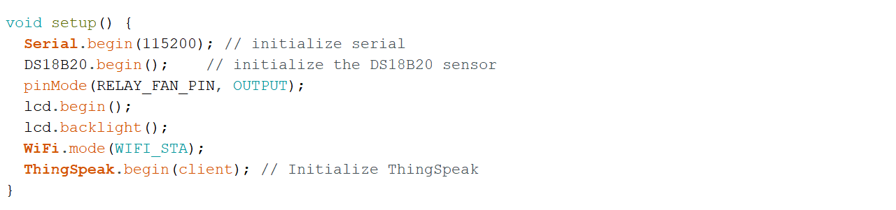
In the setup(), set the RelayPin as an output. Then, added lcd.begin() to initialize the interface to the LCD screen, DS18B20.begin() function to search for connected sensors on the bus and sets bit resolution (12 bits) for each one of them. Also added lcd.backlight() function to start the LCD backlight. WiFi.mode(WIFI_STA) sets up station mode for ESP32 to connect to an access poin. Lastly added ThingSpeak.begin(client) to initialize ThingSpeak.
 |
In the loop(), wifi connection is made. Connecting to a Wi-Fi network can take a while, so we usually add a while loop that keeps checking if the connection was already established by using WiFi.status(). When the connection is successfully established, it returns WL_CONNECTED. To get the status of the Wi-Fi connection, I used WiFi.status(). This returns WL_CONNECTED value, when it is connected to a WiFi network. I then used WiFi.begin() to connect to a network.
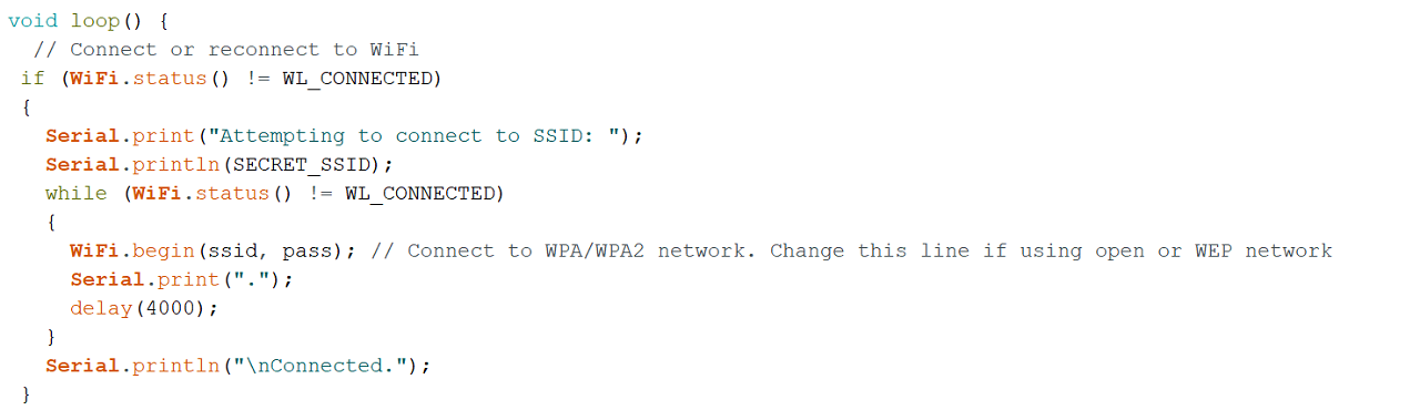 |
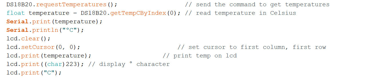
DS18B20.requestTemperatures() function is used to send command for all sensors on the bus to perform a temperature conversion. Defined 'temperature' as a float. DS18B20.getTempCByIndex(0) function reads and returns temperature reading from the sensor. deviceIndex is nothing but the location of the sensor on the bus. If you are using only one DS18B20 on the bus, set it to 0. The additional ones will be 1, 2, 3 and so on after the first one as 0.
Then, lcd.setCursor(0, 0) Move cursor to the desired position (column_index, row_index), (0, 0) in this case. lcd.print(temperature) prints Temperature value read by the sensor.
 |
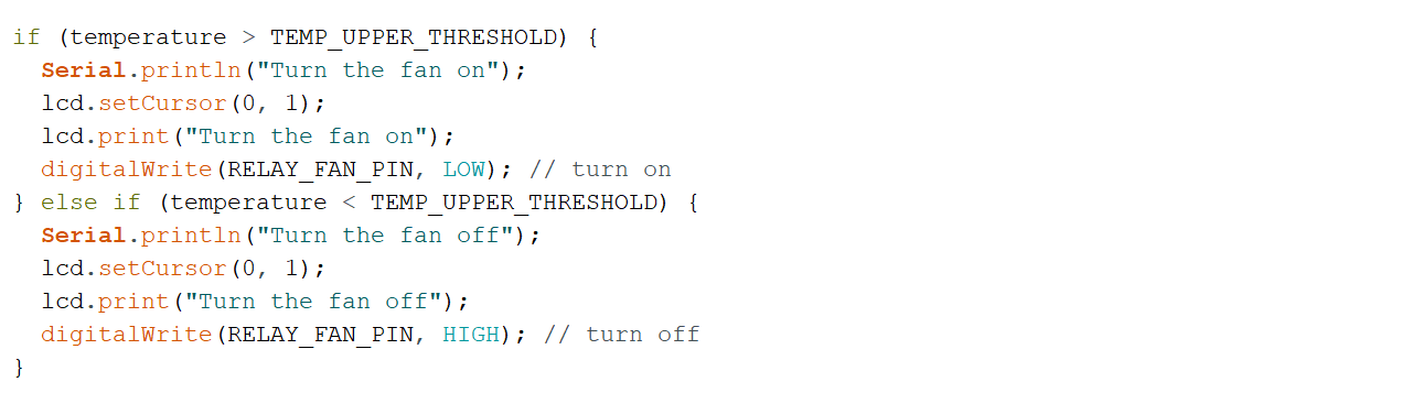
The if statement in the code reads the temperature values and takes appropriate action with regard to the Relay pin. The logic works like this, if the temperature goes above the upper threshold value defined earlier in the code, the microcontroller turn relay's GPIO pin HIGH and LOW if it is below the upper threshold value.
 |
Lastly, I defined an int x to push the temperature values on to the field#1 I have created on my ThingSpeak channel. The channel ID and myWriteAPIKey are already declared in the code above.
 |
How to create ThingSpeak IoT Channel:
Following are the steps I used to create my account and channel on ThingSpeak IoT channel. I first went to mathworks site to create my account with mathworks.
 |
 |
 |
 |
 |
 |
After mathworks account has been created, I went to ThingSpeak site to login using my mathworks log in credentials.
 |
 |
After login on thingspeak.com, go to channel tab and create new channel.
 |
Inside newly created channel, I added two fields as below, one for temperature and other for humidity (as a next part of this assignment and project).
 |
This is how the channel will look like in private and public view.
 |
To make channel public, make changes in the channel settings as shown below.
 |
To know channel WriteAPIKey, go to API keys tab as shown below.
 |
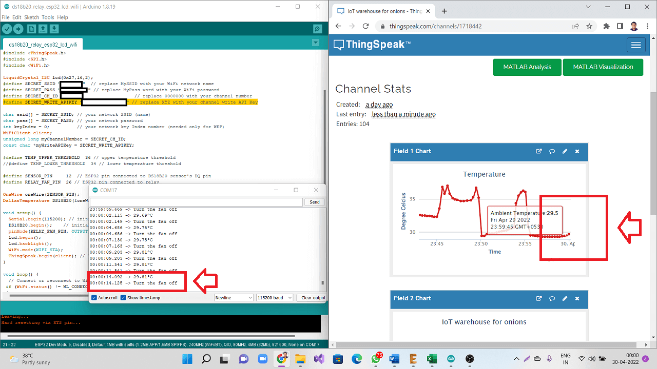
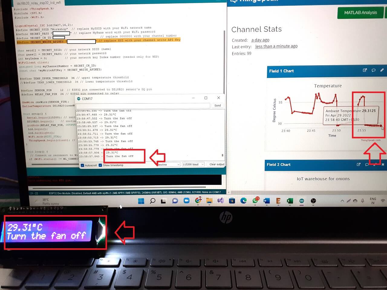
Wifi code working and publishing data to ThingSpeak channel:
This is how the code is working and publishing temperature data to my ThingSpeak channel
|
|
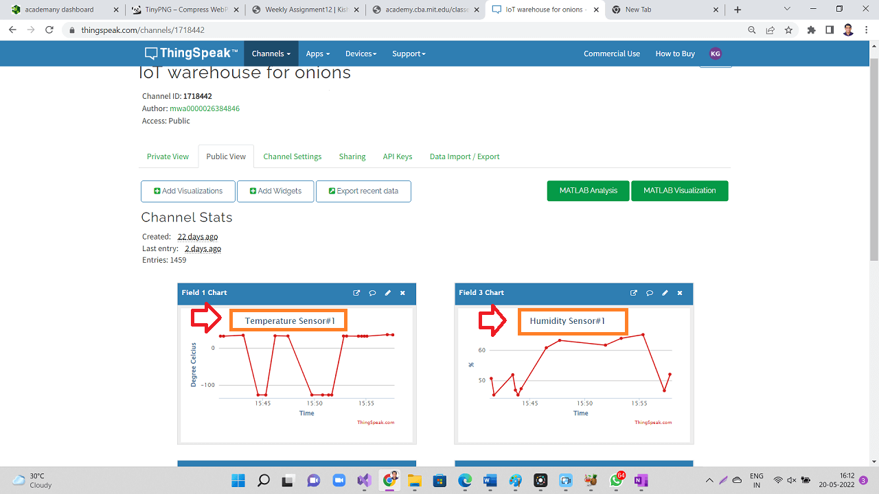
The picture below is from the next part of my project, where I have added more than one sensor on onewire bus and also have started collecting the humidity values. I just added that picture though humidity data capturing was not a part of this code and assignment.
|
Failure: Issues indentified with MQ2 gas sensor and wifi
As mentioned in my last assignment of input devices, I was able to connect MQ2 gas sensor that I am going to use to detect the level of methane released from the rotten onions in the storage. I was able to test the connection and working of this gas sensor along with DS18B20 temperature sensor, relay and LCD. The connections, code and logic worked perfectly well as to control the relay based on both or either of the values of temperature and gas concentration.
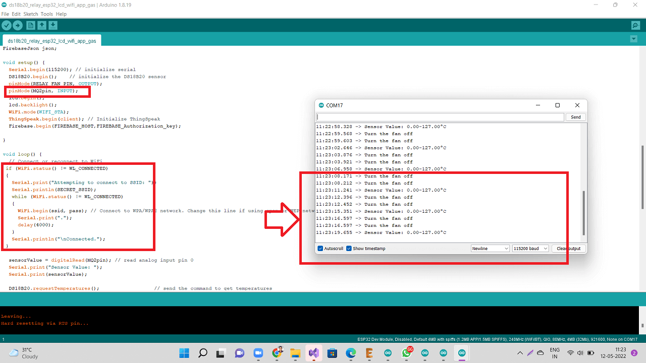
However, as I started to make that code work with wifi for this week's assignment, I was having problems with getting gas sensor's analog values. I initially thought it was a problem with my code. I went through every single line of code at least 5-6 times and verified if I made any mistakes while adding wifi code to my earlier program I wrote till I incorporated gas sensor with temperature sensor and other output devices. However, there was no single mistake in the code. The code was also able to get compiled.
Then, I started looking in to the wiring and connections. That too was perfectly ok. So, what was the problem? I kept wondering and I started troubleshooting everything, which took more that 4-5 hours. I could not do any other work that day. I also looked for any help online and I could not find any solution till late in the evening and I got more frustrated.
The second image below shows that the serial monitor of arduino IDE was showing temperature readings but the gas sensor values were 0 always.
Click here to see/copy program for MQ2+DS18B20+wifi program or download sketch from the cloud screen below.
 |
These two field values are also reflected on my ThingSpeak IoT channel and you can see the Gas sensor values are 0 there too.
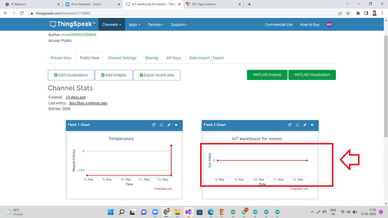 |
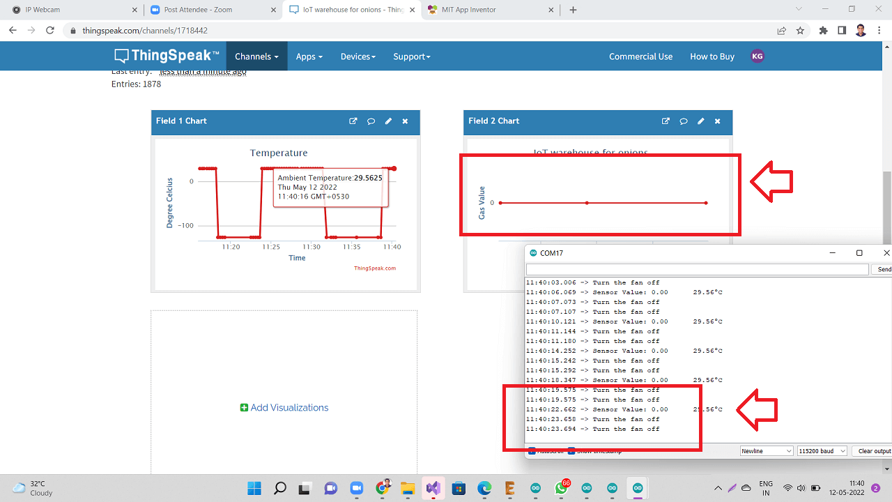 |
Then I found online about this issue, someone had already faced very similar issue before. They too were not getting MQ2 analog values when connected to wifi, otherwise they too were getting readings. Click here to read more about this question on the arduino forum.
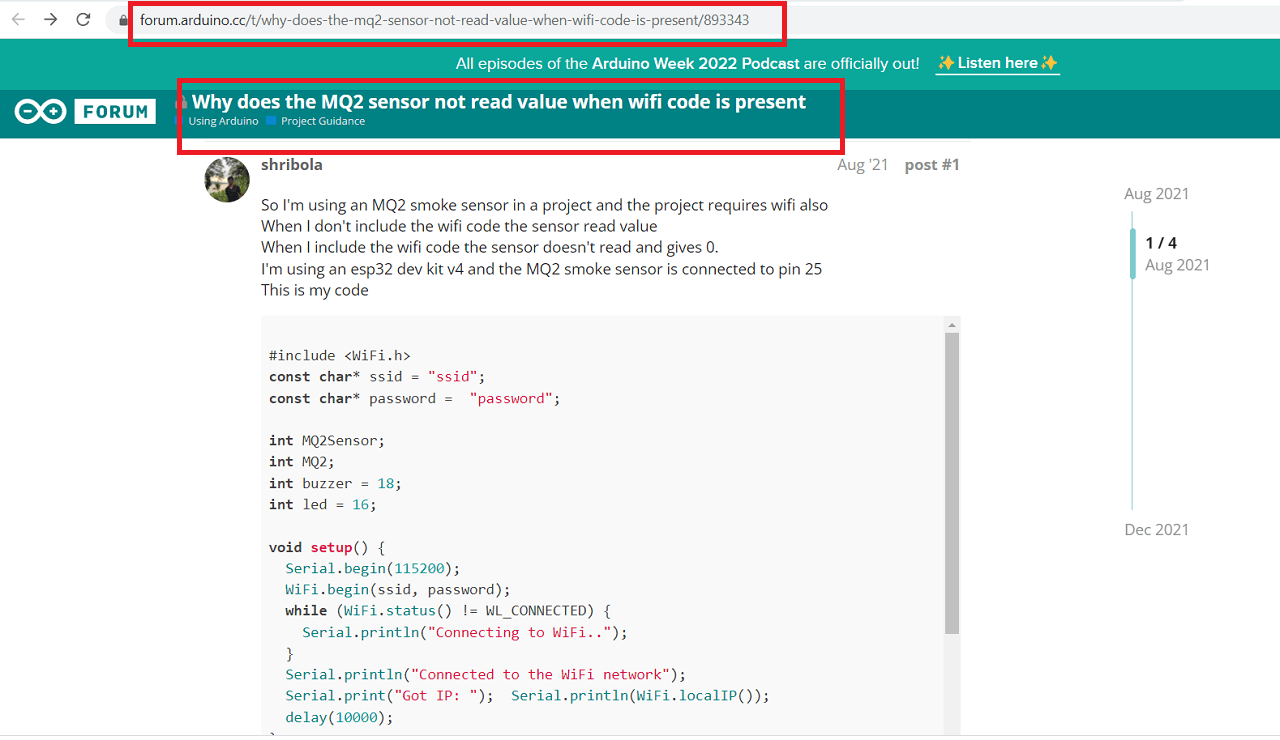 |
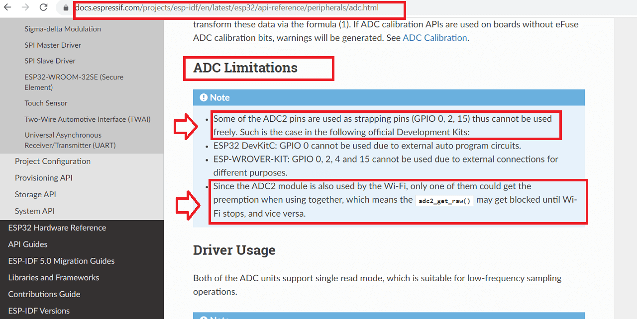
Then someone asked them to change the analog pin to a different analog pin on the board. Also, they suggested to go through espressif's website to read more about limitations of certain ADC pins while wifi is active.
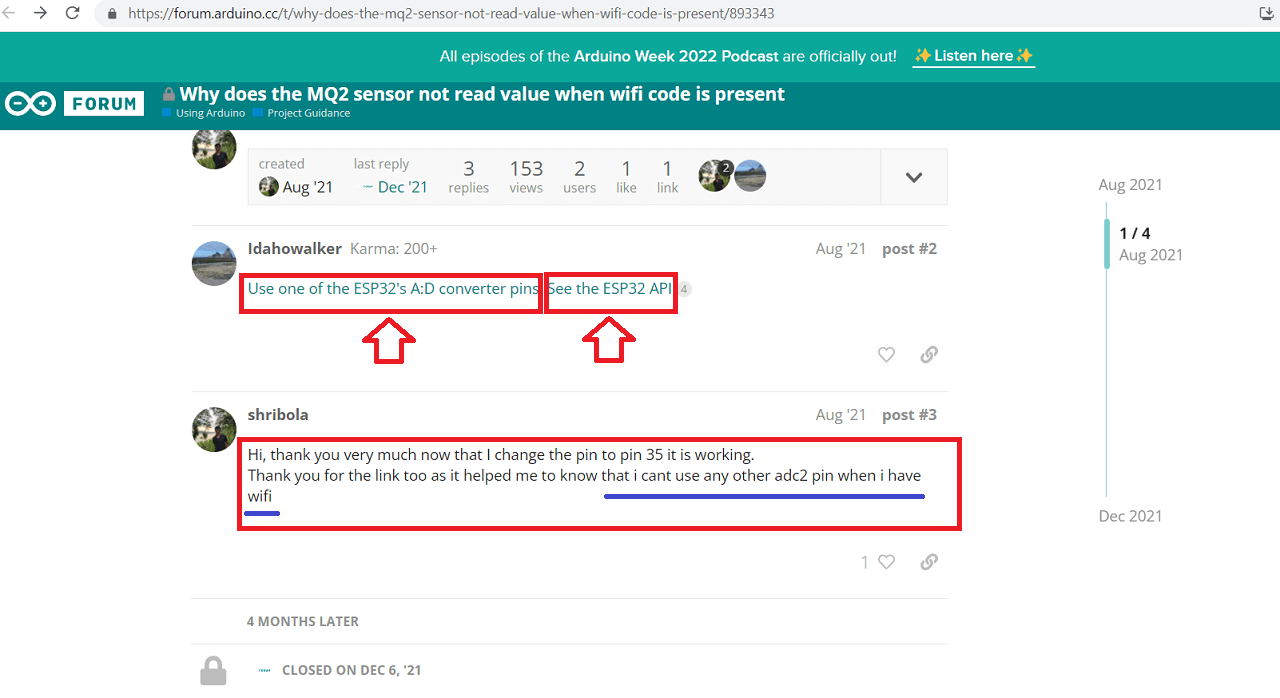 |
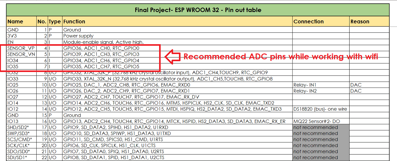
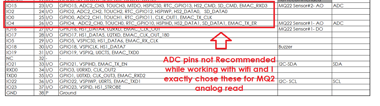
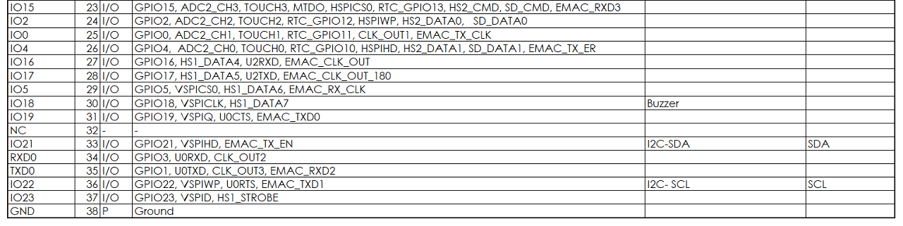
While I too was going through these limitations of ADC pins on ESP32 microcontroller then I found that there are two sets of ADC pins, out of, which they have recommened to use ADC pins- GPIO 34, 35, 36 and 39 and they have NOT recommended to use ADC pins- GPIO 0, 2,4 and 15 while using wifi.
Since, I have made connections only to the ADC pins GPIO 4 and 15 for MQ2 sensor's analog read, I am not able to use both ADC pin and wifi together. Either of them will work. With wifi code, these ADC pins will not work. Without, wifi, they had worked for sure in my case. However, I have not made connections to the recommended set of ADC pins GPIO 34, 35, 36 and 39 while designing my board, I can not use these pinouts any more for the purpose of MQ2 gas sensor's analog read.
 |
 |
 |
Then, I spoke to my Fab lab instructor, Suhas sir and discussed any other possibilities to use the gas sensor with digital pinout. However, since they give only 0 or 1 readings, it is not recommended to use the digital pins for gas sensors. So, we decided to park the use of MQ2 gas sensor for my project for now and concentrate on effectively using the temperature and humidity sensors and their readings to control the exhuast fans in my project and use MQ2 sensor in next spiral. I would appreciate if anyone has any other suggestion on this issue.
Designed a new board: Integrated MQ2 gas sensor with other peripherals and wifi
Since, I was having problems with getting gas sensor's analog values along with wifi, I could not integrate the MQ2 sensor in my system. So, I decided to design a new board with different analog and digital pins assigned to the MQ2 sensor so as to make it work with wifi as per the images shown below.
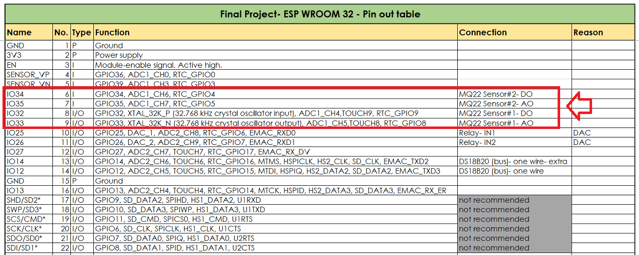 |
 |
I then redesigned the schematic and board file in eagle as shown below.
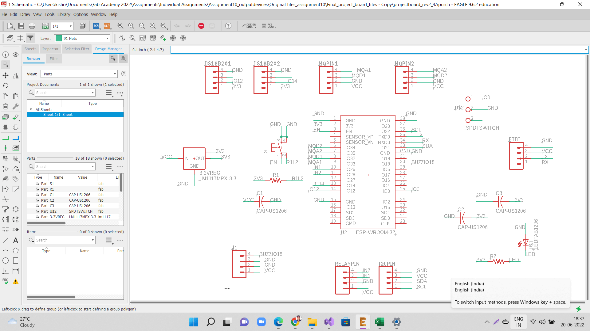 |
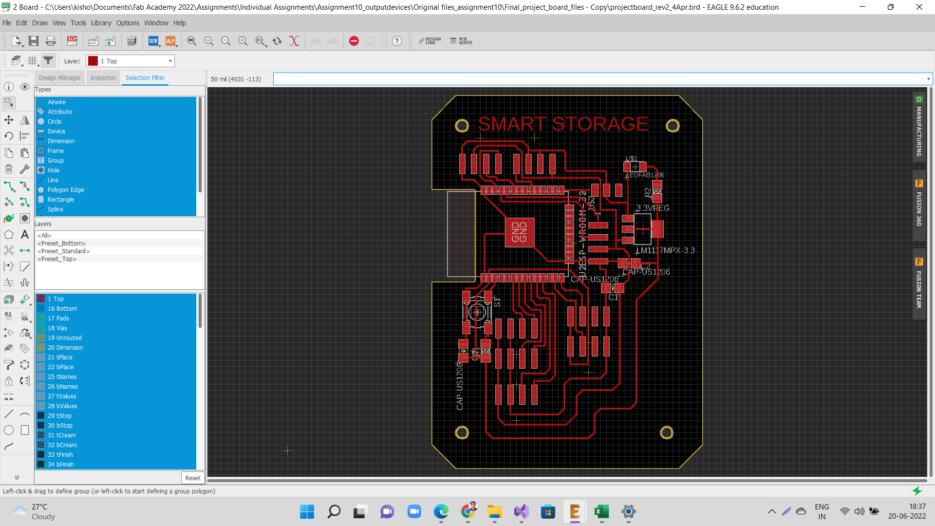 |
Following are traces and outer cut png files that I used for generating the toolpath.
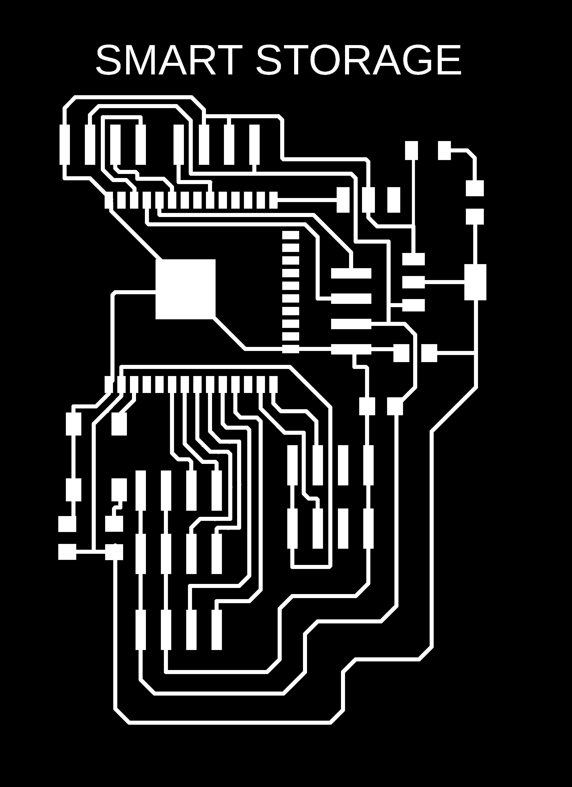 |
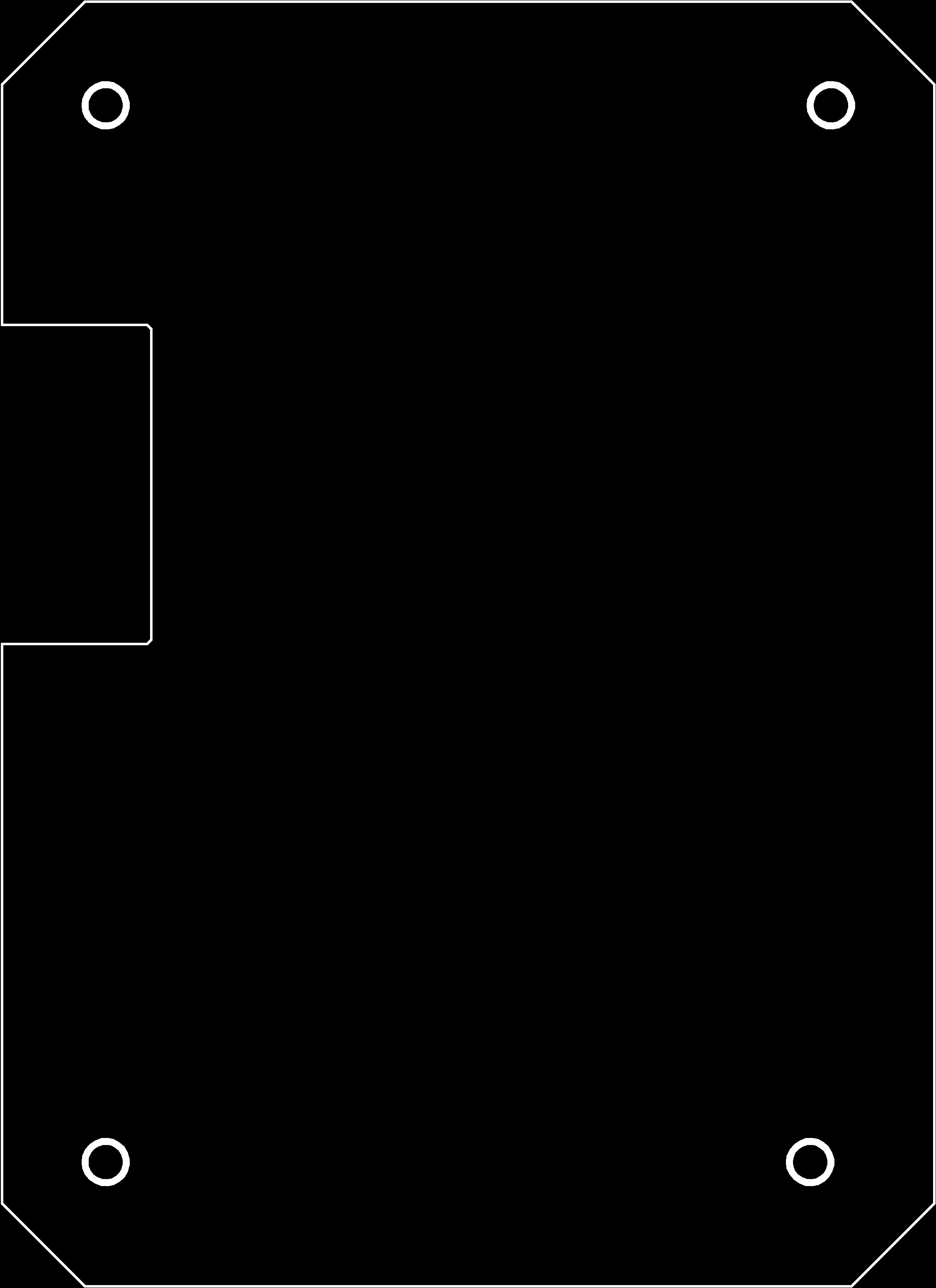 |
I assembled the new board as shown below.
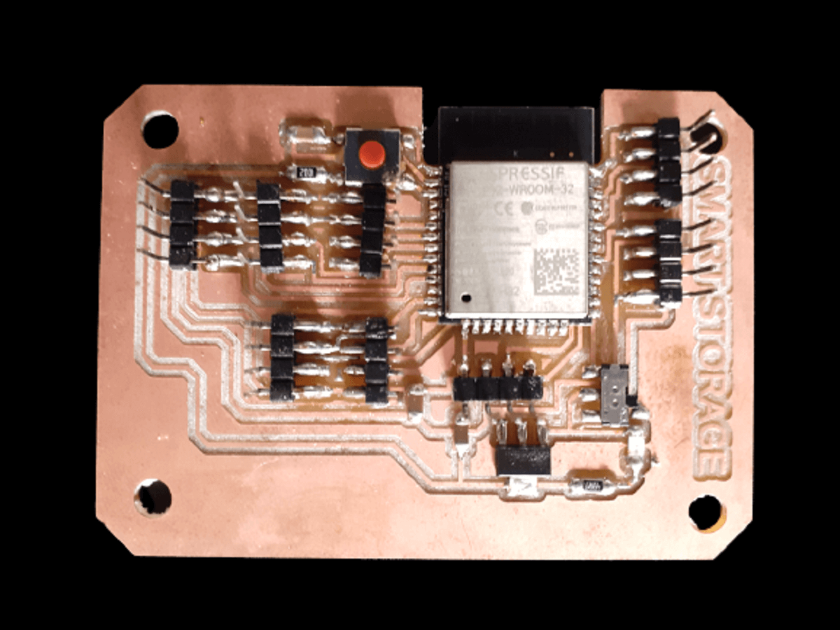 |
I have added programming and testing part of system including temperature, humidity and gas sensors along with networking and application development in next assignment of application.
Click here to go back to the topDownload Original Files
Click here to download all original files.
Click here to go back to the topWhat went well
In group assignment- We were able set-up communication between two of our project boards through mqtt.
In individual assignment- I was able to connect bluetooth and wifi of ESP32 successfully after a few trials.
What went wrong
In group assignment- There is nothing major that we did wrong in the group assignment. Only thing is, we could have tried connecting more than these two boards.
In individual assignment- In last assignment, I was able to add MQ2 gas sensor to my board also integrate the code for gas sensor with other input and output devices. However, as soon as I started working wifi code, the microcontroller did not collect gas sensor readings and I figured out the reason as I mentioned above as my failure.
What I would do differently
- I would have read ESP32 and MQ2 datasheet carefully and thoroughly before assigning GPIO pins for MQ2 gas sensor while designing my final project board in Eagle.
- I will make an attempt to integrate MQ2 gas sensor along with wifi in next spiral.
Learning Outcomes
- I learned how to ingegrate different devices, their codes
- I learned how to do connect bluetooth and wifi and establish communication through them.
- I learned how to control pins through bluetooth and also collect sensor data over wifi.
- I learned what mistake I made during board design specifically for methane gas sensor MQ2. I should avoide those 4 analog pins and use any of the other analong pins while using wifi. This is my biggest learning.