Task to be Perform for this week
Group assignment:
1) In this week of group Assignment we need to work on Send a message between two project.
Individual Assignment:
Design, build, and connect wired or wireless node(s)with network or bus addresses.
Learning outcomes
1) Demonstrate workflows used in network design. 3) Implement and interpret networking protocols and/or communication protocols.
Introduction about Networking and Communications.
Fundamentals of Networking and Communications.
The field of networking and communication includes the analysis, design, implementation, and use of local, wide-area, and mobile networks that link computers together. The Internet itself is a network that makes it feasible for nearly all computers in the world to communicate.
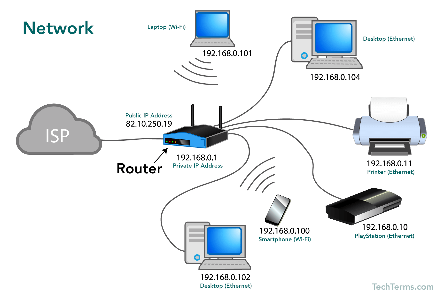
What is Network:-
A network consists of two or more computers that are linked in order to share resources (such as printers and CDs), exchange files, or allow electronic communications. The computers on a network may be linked through cables, telephone lines, radio waves, satellites, or infrared light beams.
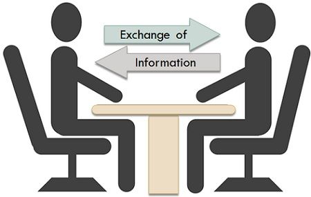
Networking is the exchange of information and ideas among people with a common profession or special interest, usually in an informal social setting. Networking often begins with a single point of common ground.
There are two common types of network.
1. Local Area Network:-A Local Area Network (LAN) is a network that is confined to a relatively small area. It is generally limited to a geographic area such as a writing lab, school, or building.
2. Wide Area Network (WAN):-Wide Area Networks (WANs) connect networks in larger geographic areas, such as Florida, the United States, or the world. Dedicated transoceanic cabling or satellite uplinks may be used to connect this type of global network.
Communications.
The communication is very well known terminology which involves the exchange of information between two or more mediums.
Computer communications describes a process in which two or more computers or devices transfer data, instructions, and information.
Some communications involve cables and wires; others are sent wirelessly through the air. As illustrated in this figure, communications systems contain all types of computers and computing devices. For successful communications, you need the following:
1. A sending device that initiates an instruction to transmit data, instructions, or information.
2. A communications device that connects the sending device to a communications channel.
3. A communications channel, or transmission media on which the data, instructions, or
information travel.
4. A communications device that connects the communications channel to a receiving device.
5. A receiving device that accepts the transmission of data, instructions, or information.
The communication between to node MCU called as Embedded Communication. for operation one side is sender and anather is receiver. it is also a bidirectional or single depend upon the users choice
Various Types of Communications
1. Serial Communication.
2. Parallel Communication.
The major difference between the serial and parallel communications is that serial communication a single communication link is used to transfer the data from one end to another As against in parallel communication, multiple parallel links are used that transmits each bit of data simultaneously.
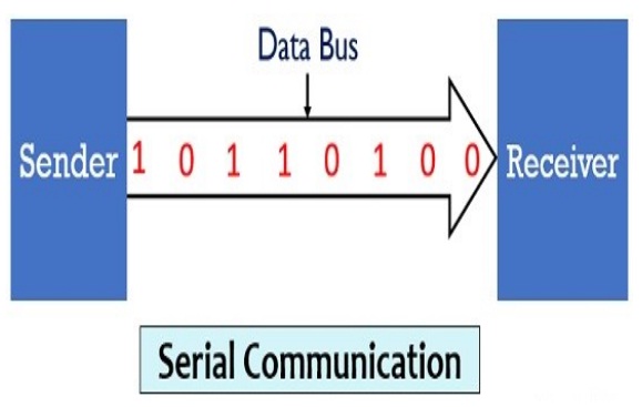
Breif About serial Communication.
Serial communication is the process of sending data one bit at a time, sequentially, over a communication channel or computer bus. This is in contrast to parallel communication, where several bits are sent as a whole, on a link with several parallel channels.
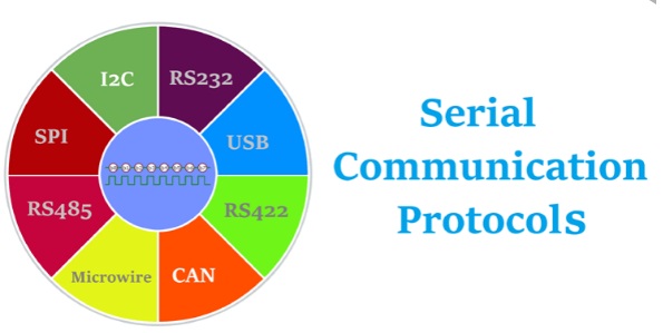
Various Serial Communication Protocols
There are several Serial Communication Protocols such as CAN, ETHERNET, I2C, SPI, RS232, USB, 1-Wire, and SATA etc.
Brief About Parrallel of Communication.
In parallel communication the various data bits are simultaneously transmitted using multiple communication links between sender and receiver. Here, despite using a single channel between sender and receiver, various links are used and each bit of data is transmitted separately over all the communication link.
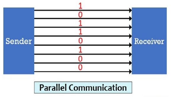
There are number of Parallel Communication Protocols are ISA, ATA, SCSI, PCI ,etc...
Again the Serial data can be transferred in two ways-Asynchronous and Synchronous.
Asynchronous Serial Communications:- Asynchronous serial communication is a form of serial communication in which the communicating endpoints' interfaces are not continuously synchronized by a common clock signal. Instead of a common synchronization signal, the data stream contains synchronization information in form of start and stop signals, before and after each unit of transmission, respectively. The start signal prepares the receiver for arrival of data and the stop signal resets its state to enable triggering of a new sequence.
Synchronous Serial Communications :- Synchronous serial communication describes a serial communication protocol in which "data is sent in a continuous stream at constant rate.
Source:- Wikipedia
So, far we have discussed about the basic communications protocol like serial and parallel communications,now lets know about the as serial protocol this series, the Inter-Integrated Circuit, or I2C.
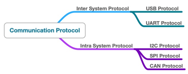
Embedded System Communications Protocol.
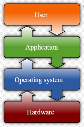
The Communications protocols mainly classified into two types.as a stated figure below
To know the more details about this I have reffered:- THIS LINK
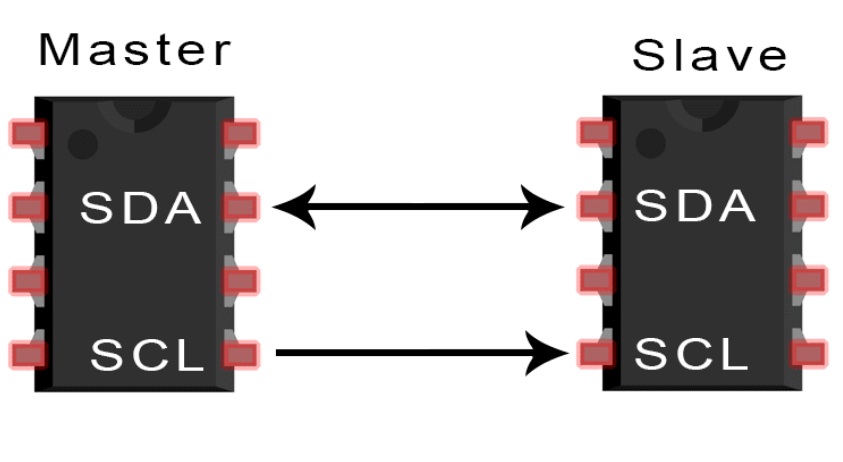
About I2C Protocol:-
I2C is a serial communication protocol, so data is transferred bit by bit along a single wire (the SDA line). With I2C, we can connect multiple slaves to a single master (like SPI) and we have multiple masters controlling single, or multiple slaves. This is really useful when we want to have more than one microcontroller logging data to a single memory card or displaying text to a single LCD.
I2C combines the best features of SPI and UARTs. With I2C, you can connect multiple slaves to a single master (like SPI) and you can have multiple masters controlling single, or multiple slaves. This is really useful when you want to have more than one microcontroller logging data to a single memory card or displaying text to a single LCD.
I2C combines the best features of SPI and UARTs. With I2C, you can connect multiple slaves to a single master (like SPI) and you can have multiple masters controlling single, or multiple slaves. This is really useful when you want to have more than one microcontroller logging data to a single memory card or displaying text to a single LCD.
This is the common protocol generally used in OLED displays, barometric pressure sensors, or gyroscope/accelerometer modules.
SDA (Serial Data) – The line for the master and slave to send and receive data.
SCL (Serial Clock) – The line that carries the clock signal.
Like SPI, I2C is synchronous, so the output of bits is synchronized to the sampling of bits by a clock signal shared between the master and the slave. The clock signal is always controlled by the master.
For More details About the Embedded Communication I have gone through this PDF LINK
About Group Assignment:-
The task for the week is to Send a message between two projects.In this week we have studied communication protocol like I2C,RS232,SPI.We have used the different microcontroller Board for communication which we have designed.
For more details about the group Assignment CLICK HERE
Individual Assignment:-
The task for the week is to design, build, and connect wired or wireless node(s)with network or bus addresses.
So, I have already desinged the ATMEGA328P Board in Input devices week link, for this week I have used HC-5 Bluetooth module for serial communication between Arduino IDE and Android Phone Applications. and Also perform the communication between Bluetooth and I2C LCD display for sending the message form android phone application to LCD display.using Bluetooth terminal HC-05 Application for Android phone.
Let's us discussed one by one how, we can communicate the bluetooth and I2C LCD display.
1) Serial Communications between HC-05 Bluetooth Module and ATMEGA328P Microcontroller Board with the help of bluetooth terminal HC-05 Android Application.
About HC-05 bluetooth Module:-
1.It is used for many applications like wireless headset, game controllers, wireless mouse, wireless keyboard and many more consumer applications.
2. It has range up to less than 100m which depends upon transmitter and receiver, atmosphere, geographic & urban conditions.
3.It is IEEE 802.15.1 standardized protocol, through which one can build wireless Personal Area Network (PAN). It uses frequency-hopping spreaspread spectrum (FHSS) radio technology to send data over air.
4.It uses serial communication to communicate with devices. It communicates with microcontroller using serial port (USART).
5.This module can be used in a master or slave configuration.
It is a six pin module can be used in two modes: data mode and command mode,
The data mode is used for data transfer between devices whereas command mode is used for changing the settings of the Bluetooth module.
it is worked on 5 volts or 3.3 volts,It has an onboard 5V to 3.3V regulator.
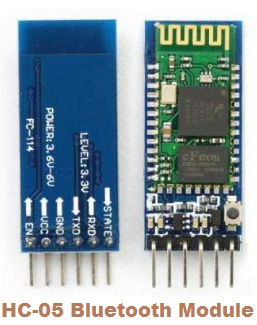
Bluetooth serial modules allow all serial enabled devices to communicate with each other using Bluetooth.
Pin Configurations and Detail.
1.Key/EN: It is used to bring Bluetooth module in AT commands mode. If Key/EN pin is set to high, then this module will work in command mode. Otherwise by default it is in data mode. The default baud rate of HC-05 in command mode is 38400bps and 9600 in data mode.
2. VCC: Connect 5 V or 3.3 V to this Pin.
3. GND: Ground Pin of module.
4. TXD: Transmit Serial data (wirelessly received data by Bluetooth module transmitted out serially on TXD pin)
5. RXD: Receive data serially (received data will be transmitted wirelessly by Bluetooth module).
6. State: It tells whether module is connected or not.
Note:- HC-05 Module has one LED Which indicate the connections status whether the bluetooth is connected or not. Before connecting HC-05 Module to any device this LED get blinks continiousl in a periodic manner. when it gets connected to any other bluetooth device its blinking shows down to two second.
As HC-05 Bluetooth module has 3.3 V level for RX/TX and the microcontroller can detect 3.3 V level,so here We no need to shift the the transmit level of the HC-05 module. But we need to shift the transmit voltage level from the microcontroller to RX of the HC-05 module.
For This week Assignemnt, As I have already my designed ATMEGA 328P Microcontroller Board. I decided to connect the Bluetooth Module to microcontroller board and send the data serially from bluetooth to Atmega328p Board and vise versa,
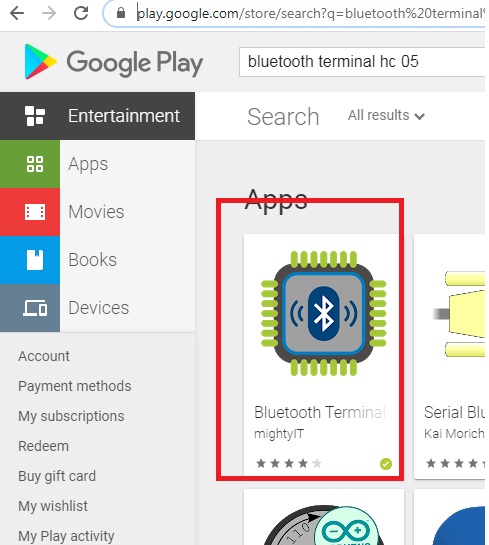
So for this type of serial communications I need to download Bluetooth Terminal-HC 05 Application in my smart Phone, First, I have downloaded and instlled this App in my smart phone HERE
Then, I had to make the connection As bluetooth HC-05 Module is the serial communication module it has RX,TX,VCC and GND.
I have connect the circuit by refferering this circuit diagram with arduino and HC-05 Module
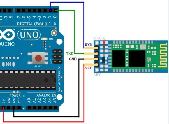
But, I have ATMEGA328P Board and this board In the code I have to define the RX,TX pin.
Connection of ATMEGA328P with Bluetooth Module.
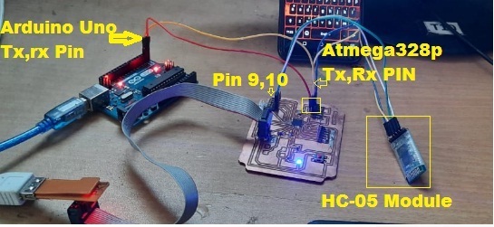
Here, I connect the circuit as above shows VCC and GND of HC-05 Module connected to VCC and GND of ATMEGA328P Board, Then RX,TX from the bluetooth module connected to digital pin 9, and 10 of Atmega328p Board. and the TX,RX pins from the Arduino UNO Connected to TX,RX of ATEMGA328P.Here Arduino UNO only used for to display the DATA on Serial Monitor of Arduino IDE.
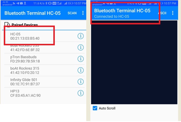
Now Once circuit get connected properly I have to run the code in arduino IDE., Before that I need to check here the LED of HC-05 module is blinking or not and in my android phone checked that it is availble or not, For this I have to open the installed bloutooth terminal-05 APP, and there is an option paired device or scan or refresh option this HC-05 is displayed in the listed then by clicking on it, shows the connected to -HC05
Once the bluetooth get connected successfully with Android Application next step is to upload the code in ATMEGA328P Board.
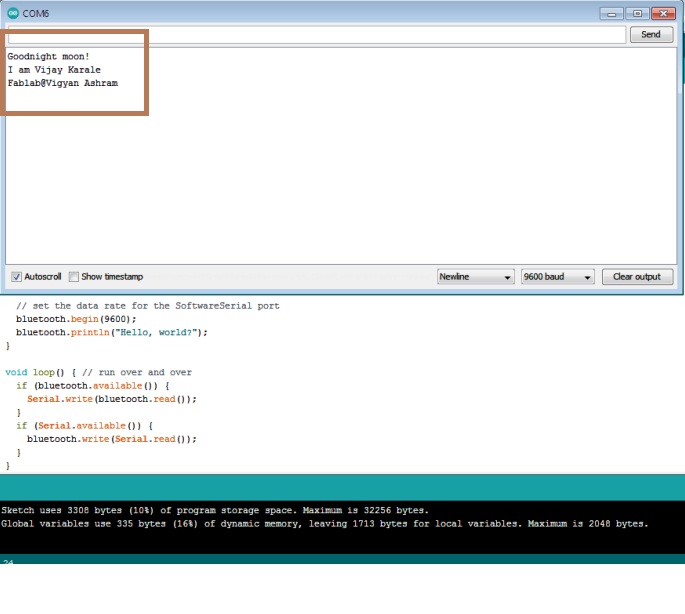
Code for Serial Communication Between Serial Monitor of Arduino IDE that is Atmega and HC-05 Module with Smart phone.
// Code for Communication between Bluetooth and serial Monitor
#include "SoftwareSerial.h"
SoftwareSerial bluetooth(9, 10); // RX, TX
void setup() {
// Open serial communications and wait for port to open:
Serial.begin(9600);
while (!Serial) {
; // wait for serial port to connect. Needed for native USB port only
}
Serial.println("Goodnight moon!");
// set the data rate for the SoftwareSerial port
bluetooth.begin(9600);
bluetooth.println("Hello, world?");
}
void loop() { // run over and over
if (bluetooth.available()) {
Serial.write(bluetooth.read());
}
(Serial.available()) {
bluetooth.write(Serial.read());
}
}
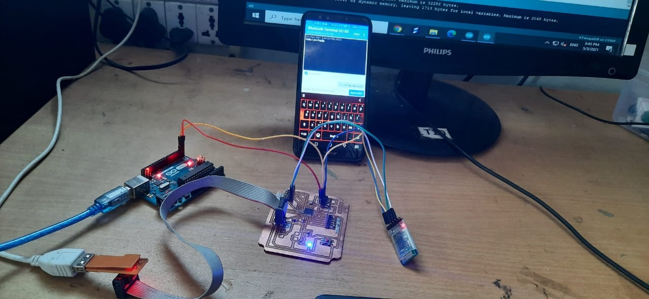
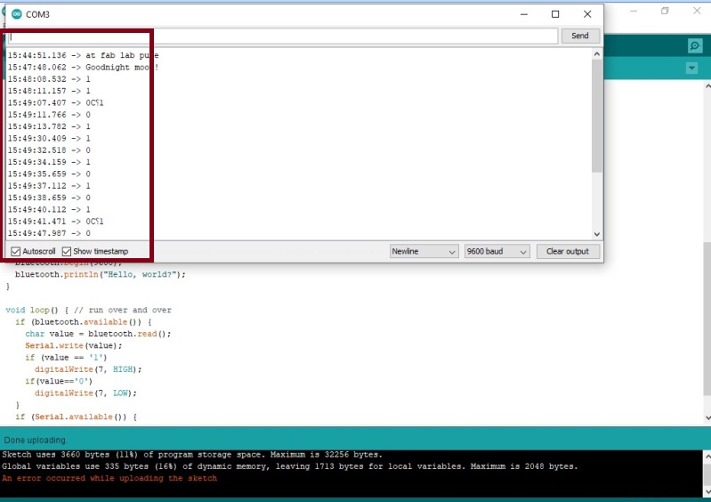
Then, the above code I have upload into Atmega328p Board with the help of FABISP Programmer and by sending some text tried to communicate between serial monitor to Bluetooth and Bluetooth to serial Monitor
The below image shows the first test appeared on serial monitor and Bluetooth aslo I have send the hello from serial monitor, This appeared on bluetooth
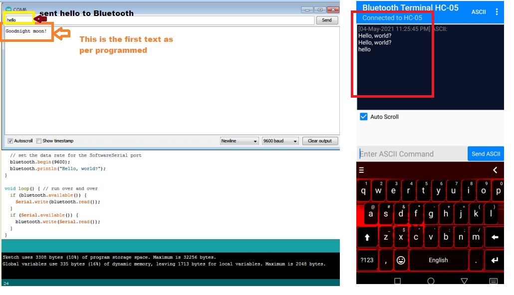
Then I have tried to send some text from bluetooth to serial Monitor window, it was working as per command .
The same text you can see here.
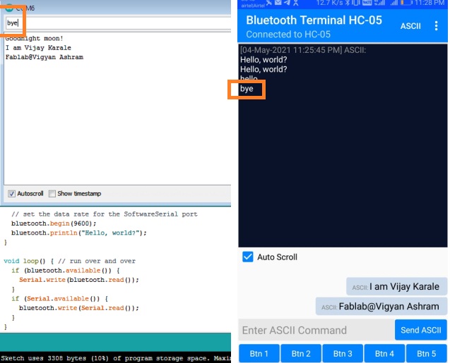
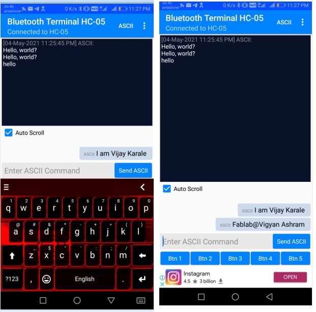
In this way I have made the serial Communications between smart phone and Serial Monitor of Atmega328p with the help of HC-05 Bluetooth module.
The video shows the Asynchronous serial Communications between Bluetooth and Serial Monitor of Microcontroller
2. Communications Between Smart Phone and ATMEGA328P Microcontroller Board to control the LED.
Then I have tried to write the code for Controlling the LED with Bluetooth Module or Smart Phone.
To ON/OFF the LED through Microcontroller ATMEGA328P Board and rest of the circuit as it is, I need to connect the LED to Digital pin number 7 of board. By connecting LED I have connect the circuit.
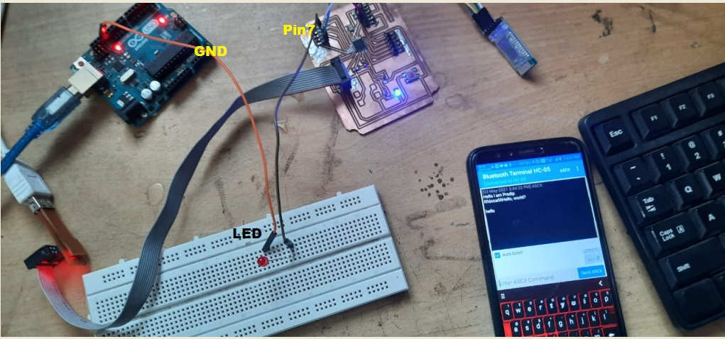
Then,I have written the program in such a way that, if I send value "1" from Bluetooth the LED will blink and When I send the value "0" the LED will OFF
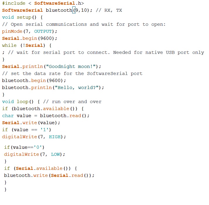
Programto Control The LED Using Bluetooth.
#include "SoftwareSerial.h"
SoftwareSerial bluetooth(10, 9); // RX, TX
void setup() {
// Open serial communications and wait for port to open:
pinMode(7, OUTPUT);
Serial.begin(9600);
while (!Serial) {
; // wait for serial port to connect. Needed for native USB port only
}
Serial.println("Goodnight moon!");
// set the data rate for the SoftwareSerial port
bluetooth.begin(9600);
bluetooth.println("Hello, world?");
}
void loop() { // run over and over
if (bluetooth.available()) {
char value = bluetooth.read();
Serial.write(value);
if (value == '1')
digitalWrite(7, HIGH);
if(value=='0')
digitalWrite(7, LOW);
}
if (Serial.available()) {
bluetooth.write(Serial.read());
}
}
The Above code I have upload in Atmega328p Microcontroller Board .
Then,This is how I have Controlled the LED from Bluetooth.
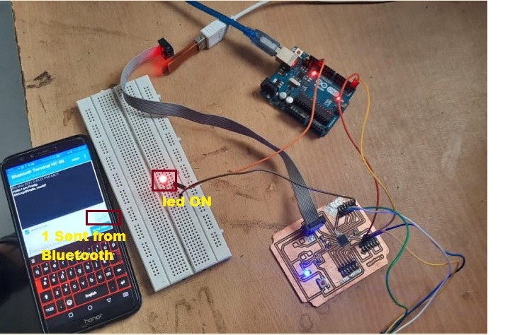
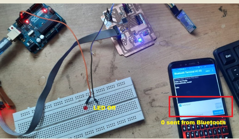
So,In this way Here I have made the Communication between Mobile phone and Microcontroller Board for Controlling the LED
Also the same digits appeared on serial monitor screen.
The video shows the communications operation.
Communication Between Bluetooth and I2C 16*2 LCD Dsiplay
In this case I have made the Communication through a bluetooth Module HC-05 Between ATMEGA328P Microcontroller Board and a smart phone show the messages that are sent from the phone in a I2C,16X2 LCD, connected to the Atmega328p Board.
Here Hardware to be required as follow.
1.ATMEGA328 Microcontroller Board 1
2. i2c LCD Back Module 1
3. Bluetooth Module HC-05 1
4. Male to Female Jumper Wires 8
5. Male to Male Jumper Wires 2
After that I have made the connection as follow.
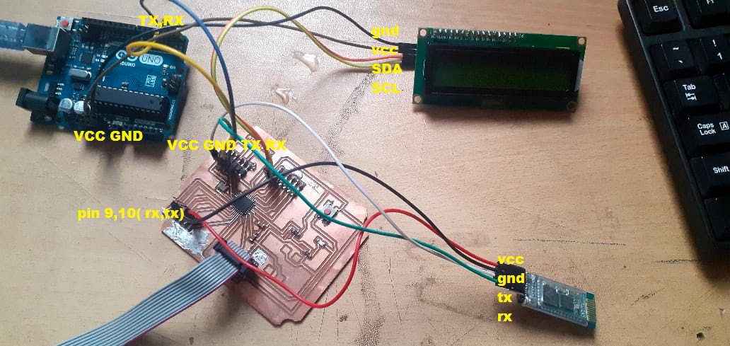
The above Circuit connected as per The four wire from LCD i.e. VCC,GND,SDA,SCL Connected to VCC,GND of Arduino uno and A4,A4 of Atmega328p Board respetively. Then the four wire from bluetooth HC-05 Module i.e. RX,TX,VCC,GND connected to Digital Pin 9,10 ,VCC,GND of Atmega328P Board.Then to display the value on serial monitor I had to connect RX,TX of Atmega328p board to RX,TX of arduino Uno Board.
To conduct this communication I need smart phone with installed app Bluetooth terminal HC-05,So I have already installed this app.
Once the circuits get connected properly I had to power up the circuit so I need to connect the UsbtinyISP as programmer to ATMEGA328P Board and conneted to usb board of my computer system and arduino uno also power up.
Then, I have written a program in such a way that whatever the text i witten in the bluetooth app that should be display on I2C 16*2 LCD module.
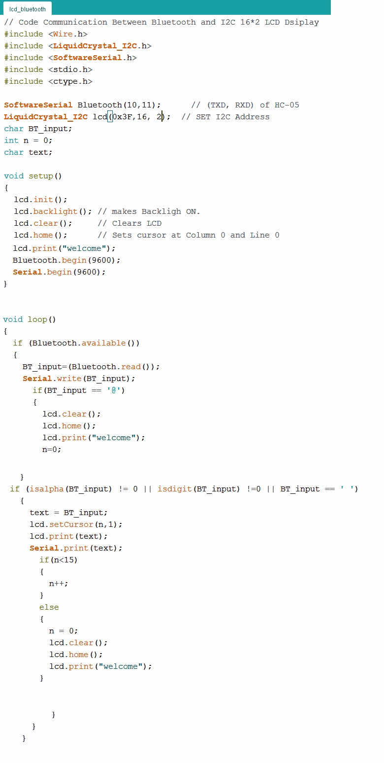
The programm as follow.
// Code Communication Between Bluetooth and I2C 16*2 LCD Dsiplay
#include "Wire.h"
#include "LiquidCrystal_I2C.h"
#include "SoftwareSerial.h"
#include "stdio.h"
#include "ctype.h"
SoftwareSerial Bluetooth(9,10); // (TXD, RXD) of HC-05
LiquidCrystal_I2C lcd(0x3F,16, 4); // SET I2C Address
char BT_input;
int n = 0;
char text;
void setup()
{
lcd.init();
lcd.backlight(); // makes Backligh ON.
lcd.clear(); // Clears LCD
lcd.home(); // Sets cursor at Column 0 and Line 0
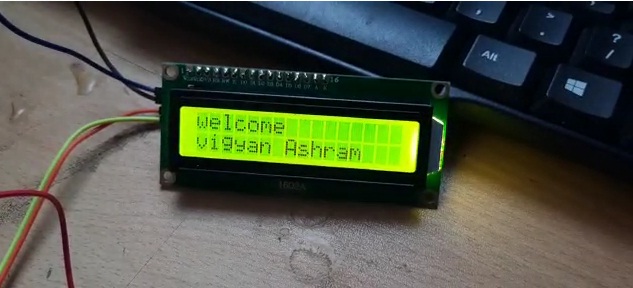
lcd.print("welcome");
Bluetooth.begin(9600);
Serial.begin(9600);
}
void loop()
{
if (Bluetooth.available())
{
BT_input=(Bluetooth.read());
Serial.write(BT_input);
if(BT_input == '@')
{
lcd.clear();
lcd.home();
lcd.print("welcome");
n=0;
}
if (isalpha(BT_input) != 0 || isdigit(BT_input) !=0 || BT_input == ' ')
{
text = BT_input;
lcd.setCursor(n,1);
lcd.print(text);
Serial.print(text);
if(n<15)
{
n++;
}
else
{
n = 0;
lcd.clear();
lcd.home();
lcd.print("welcome");
}
}
}
}
The above programmed I have uploaded on ATMEGA328P Microcontroller Board with the help of Arduino IDE.
Here for communication with I2C lcd we need to scan i2c address first that I have written in my above program.
First to scan the I2C Adress i have upload the above below program in arduino IDE and Find out the I2C Adress.
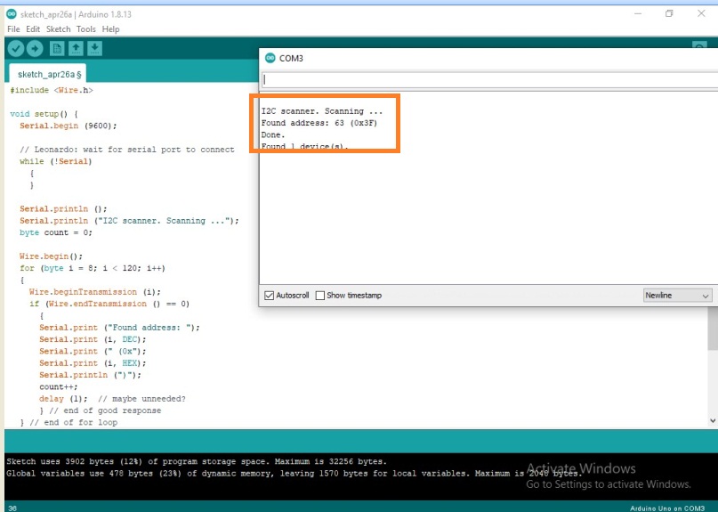
Here I got the I2C Adress i.e."0x3F"
Once, got the I2C Adress, put this address into the main program.
How the Program works:-
1. The fisrt case after uploading done success fully the I2C LCD Print the "Welcome" text.
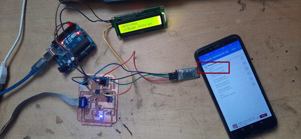
2. Open the bluetooth terminal application from smart phone.
3. Press scan for serching the HC-05 Bluetooth Module once device get connected you can send the any messages from smart phone to LCD display for making the communication between them .
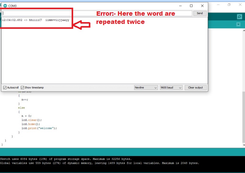
Here, the communications was made successfully between smart phone and the I2C lcd through ATMEGA328P board but the text displayed on serial monitor of arduino IDE not proper " "repeated the words twice" So i have faced this problem while Communicating.
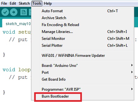
I thought that This error is due to not proper communications between the smart phone or might be because of the not proper coding. So I have once again checked the coding, but this issue due to communication frequency for that as neil suggested in electronic production week, In this case we need to run the boot loader in arduino IDE, so In arduino IDE go to tool menu and select the boot loader option here.
Then, This issue had solved and serial monitor are able to read the proper text.
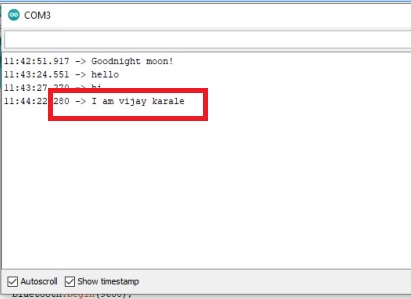
In this way I have tried to make a communication between serial Monitor , I2C LCD display and my smart phone with the help of HC-05 bluetooth Module and it was done sucessfully.
DOWNLOAD's
Download my original file here