Task to be Perform for this week
Group assignment:
1) Measure the power consumption of an output device
2) Document your work (in a group or individually)
Individual Assignment:
Add an output device to a microcontroller board you've designed and program it to do something
Learning outcomes
Demonstrate workflows used in controlling an output device(s) with MCU board you have designed
Introduction about Output devices.
What Does Output Device Mean?
An output device is any hardware device used to send data from a computer to another device or user.
Usually, most output peripherals are meant for human use, so they receive the processed data from the computer and transform it in the form of audio, video, or physical reproductions.
Typical examples of output devices are monitors and projectors (video), headphones and speakers (audio), or printers and plotters (physical reproduction in the form of text or graphics).
Various Component's used in output devices is as follow
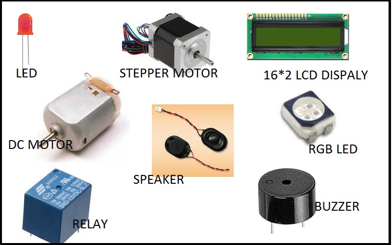
Output devices in electronic systems transform electrical energy into another type of energy, such as light, sound or kinetic energy.
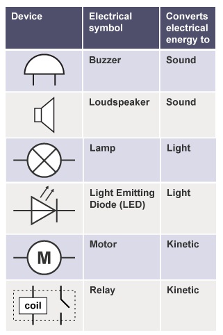
Common output devices and their associated energy changes are shown in the below. SOURCE:- INTERNET
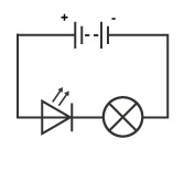
About Light Emitting Diode:-
Unlike filament lamps, where electrical energy must be converted into heat before light can be produced, Light Emitting Diodes (LEDs) are able to transform electrical energy directly into light energy.
Since the LED is a diode, it will only light up when current is in the correct (conducting) direction
DC Motors:-
A DC motor is any of a class of rotary electrical machines that converts direct current electrical energy into mechanical energy. The most common types rely on the forces produced by magnetic fields. Nearly all types of DC motors have some internal mechanism, either electromechanical or electronic, to periodically change the direction of current flow in part of the motor.
Stepper Motor:-
A stepper motor is a brushless, synchronous electric motor that converts digital pulses into mechanical shaft rotations. Each rotation of a stepper motor is divided into a set number of steps, sometimes as many as 200 steps. The stepper motor must be sent a separate pulse for each step.
SERVO MOTOR-
A servomotor is a rotary actuator or linear actuator that allows for precise control of angular or linear position, velocity and acceleration. It consists of a suitable motor coupled to a sensor for position feedback
PIEZO BUZZER-
Piezo buzzer is an electronic device commonly used to produce sound ,Piezo buzzer is based on the inverse principle of piezo electricity discovered in 1880 by Jacques and Pierre Curie ,It is the phenomena of generating electricity when mechanical pressure is applied to certain materials and the vice versa is also true. Such materials are called piezo electric materials
LCD DISPLAY-
LCD (Liquid Crystal Display) screen is an electronic display module and find a wide range of applications. A 16x2 LCD display is very basic module and is very commonly used in various devices and circuits.
RELAY-
A relay is an electrically operated switch. Many relays use an electromagnet to mechanically operate a switch, but other operating principles are also used, such as solid-state relays. Relays are used where it is necessary to control a circuit by a separate low-power signal, or where several circuits must be controlled by one signal. The first relays were used in long distance telegraph circuits as amplifiers: they repeated the signal coming in from one circuit and re-transmited it on another circuit.
RGB LED-
RGB LED means red, blue and green LEDs. RGB LED products combine these three colors to produce over 16 million hues of light. Note that not all colors are possible. Some colors are “outside” the triangle formed by the RGB LEDs. Also, pigment colors such as brown or pink are difficult, or impossible, to achieve.
Group Assignment:-
In this week of group assignment measure the power consumption for an output Devices. So during this week task I have measure the power consumption for 16*2 LCD Display and the power Comsumption for Nima 17 Biopolar Stepper motor.
In group task we have measure the power consumption of various devices like, Exhaust Fan, DC motor Pump, LCD Display ect...
Lets See what is the Power and how we can measure the power Consumption for Any electric or electronics Device.
The Images Shows the How to Calculate Power, Voltage , Resistance and Current.
V comes from "voltage" and E from "electromotive force (emf)". E means also energy, so we choose V. Energy = voltage × charge. E = V × Q. Some like better to stick to E instead to V, so do it. For R take Z.
Some most Important Formulas
1. Voltage V = I × R = P / I = √(P × R) in volts V.
2. Current I = V / R = P / V = √(P / R) in amperes A.
3. Resistance R = V / I = P / I2 = V2 / P in ohms Ω.
4. Power P = V × I = R × I2 = V2 / R in watts W.
For More detail about the Group assignment CLICK HERE
What is Current:-The rate of flow of charges with respective time is called current and the SI Unit of current is Ampere denoted by "A"
What is voltage:-it is an an electromotive force or potential difference between two point expressed in volts
What is power:-In physics, power is the amount of energy transferred or converted per unit time. In the International System of Units, the unit of power is the watt, equal to one joule per second. In older works, power is sometimes called activity. Power is a scalar quantity.
Power is the rate with respect to time at which work is done; it is the time derivative of work:P=dW/dt,where P is power, W is work, and t is time.
The SI unit of power is Watt.
Calculations of Power Consumption for NIMA-17 Stepper Motor:-
I have measure the Required power Consumption for Stepper motor Here.when motor is Controlling through Atmega328p Board with A4988 motor Driver.
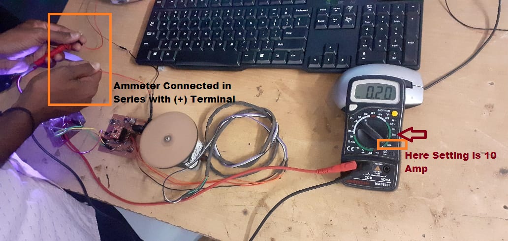
Measuring the Current Required for Stepper Motor
For controllling the stepper motor through any microcontroller board we required driver circuit and this driver circuit required 12Volts Dc power from external Source.
Then I have measure the required current for Biopolar stepper motor by connecting Ammmeter in series with the possitive supply terminal of external voltage source i.e. 12 Volts. Beacuse for calculating the power consumption of given Motor i required the values of Voltage and Current.
The total current flowing through the circuit is 0.20 Amp When motor is on noload conditions for stepper motor is
So, here it is observed that the total power comsume by the stepper motor as per formulas i.e. p(t)=v(t)*i(t)
P(t)= 12*0.20=2.4 Watt
Calculations of Power Requirement for 16*2 LCD display:-
16*2 LCD Display with I2C module.
For measurement of power for 16*2 LCD display, first we should know the current total current drawn by the circuit when LCD connected to Atmega328p Microcontroller Board.
So, Here for measurement of current flowing through the circuit ,i have connected multimeter in sries with the circuit which is connected to LCD Display.
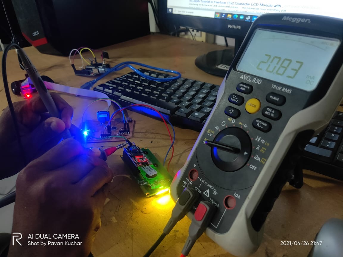
16*2 LCD Display with I2C module.
Here, The multimeter shows the reading 20.83 mAmp when LCD Connected to Atmega328p Microcontroller Board means the voltage is given to the circuit is 5 volts.
So, The total Power required for the 16*2 LCD Display is Voltage V(t)= 5volts and Current I(t)= 0.20mAmp
Total Power P(t)= V(t)*I(t)=5 volts*20.83mAmp=0.10415 Watt.
Individual Assignment:-
The task for the week is to add an output device to a microcontroller board we have designed and program it to do something.
For completion this week task I have decided to worked output devices which i am going to use for my final project.
Flow of Individual Assignment:-
1) Testing of Stepper motor with Arduino UNO Microcontroller Board.
2) Testing of 16*2 LCD Display with Arduino Uno Board.
3) Designing, Milling and Soldering of A4988 Driver Sheild Circuit In Eagal Software.
4) Testing of NIMA 17 Biopolar Stepper Motor with My designed Atmega328p and A4988 Driver Shield Board.
5) Testing of LCD Display with Atmega328p Miicrocontroller Board.
About NIMA-12 Biopolar Stepper Motor:-
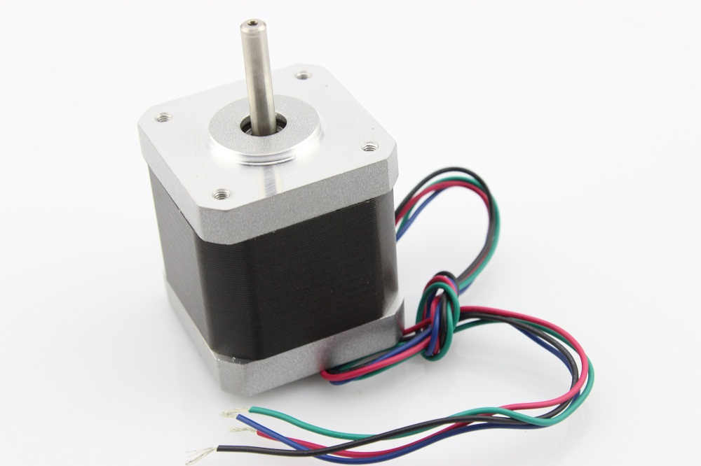
NIMA-17 Stepper Motor.
Stepper motors are different from DC motors in that they have to be pulsed to move in set increments. That means you can't simply hook them up to a power supply to make them go, but they have other advantages, like accurate positioning (1 pulse=1 increment of movement), and lots of low-speed torque (ability to twist things). This 4-wire bipolar stepper has 1.8° per step for smooth motion and a nice holding torque. This NEMA-17 stepper motor produces a whopping 4800g*cm of holding torque. SOURCE-HERE
In our FABLAB at Vigyan Ashram NEMA17 5.5 kg-cm Stepper Motor is available with following Details.
This stepper motors move in precisely repeatable steps, hence they are the motors of choice for the machines requiring precise position control. The NEMA17 5.5 kg-cm Stepper Motor can provide 5.5 kg-cm of torque at 1.5A current per phase.
The motor’s position can be commanded to move or hold at one position with the help of Stepper Motor Drivers. The NEMA17 5.5 kg-cm Stepper Motor provides excellent response to starting, stopping and reversing pulses from stepper motor driver.
They are very useful in the various application especially which demands low speed with high precision. Many machines such as 3D Printers, CNC Router and Mills, Camera Platforms, XYZ Plotters etc.
It is a brushless DC motor, so the life of this motor is dependent upon life of the bearings. The position control is achieved by a simple Open Loop control mechanism so doesn’t require complex electronic control circuitry.
The motor’s shaft has been machined for good grip with a pulley, drive gear etc. and especially avoiding stall or slip.
To know the more details about specifications and all this Click here
Testing and controlling of Stepper Motor with Arduino Uno Microcontroller Board.
For testing and controlling of this stpper motor i have used A4988 driver available with us.
NIMA-17 Stepper Motor.
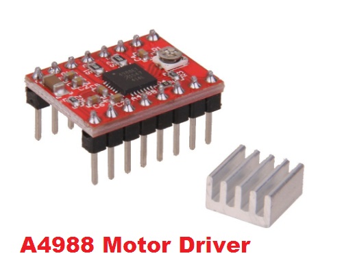
About A4988 Stepper Motor Driver:-
The A4988 is a micro-striding driver for governing the stepper motors, it is incorporated with the interpreter (translator) for the tranquil process. By this controller stepper motor can control by 2 pinouts, one pin is to regulate the direction of motor revolutions and other is for steps regulation of motor.It works on 3 to 5.5V and it consumes per phase two amperes current in presence of the proper cooling environment. It consists of an immovable off-time current controller which has the capacity to works in sluggish or assorted falling-off styles.
Firstly,I have reffered the Pin out of this module
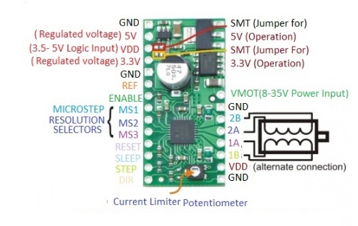
PIN OUT
Then, I have download and read the datasheet of this A4988 Module DATASHEET
Then i have read the specicfications
A4988 Stepper Motor Driver - General Specifications
-Simple step and direction control interface.
-Five different step resolutions.
-Adjustable current control lets you set the maximum current output with a potentiometer.
-Intelligent chopping control that automatically selects the correct current decay mode (fast decay or slow decay).
-Over-temperature thermal shutdown, under-voltage lockout, and crossover-current protection.
-Short-to-ground and shorted-load protection.
A4988 Stepper Motor Driver - Technical Specifications
-Minimum operating voltage: 8 V
-Maximum operating voltage: 35 V
-Continuous current per phase: 1 A
-Maximum current per phase: 2 A
-Minimum logic voltage: 3 V
-Maximum logic voltage: 5.5 V
-Microstep resolutions: 1, 1/2, 1/4, 1/8, 1/16
-Size: 0.6″ × 0.8″
-Weight: 1.3 g
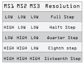
So this Driver provides five different step resolutions full-step, haft-step, quarter-step, eight-step and sixteenth-step. Also, it has a potentiometer for adjusting the current output, over-temperature thermal shutdown and crossover-current protection.
Its logic voltage is from 3 to 5.5 V and the maximum current per phase is 2A if good addition cooling is provided or 1A continuous current per phase without heat sink or cooling.
After, knowing the all detail about driver circuit and stepper motor i had moved to, How we can control the stepper motor with A4988 driver using Arduino Uno Microcontroller Board. for that I have reffered this tutorial howtomechatronics.com
For controlling the stepper motor with A4988 Driver and Arduino, here we can control the stepper motor with just 2 pin of our microcontroller board.one for controlling the rotation or directions and other for controlling its steps.
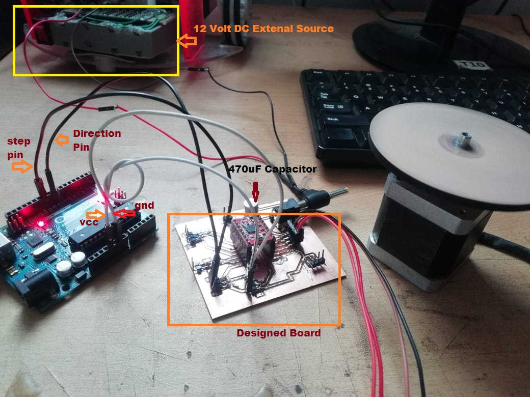
This how we can connect the stepper motor with driver and Arduino uno Microcontroller Board.
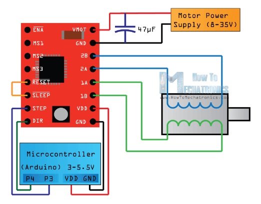
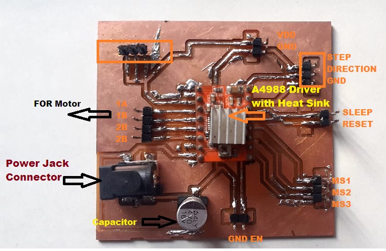
Connections
So here I started with by connecting 2 pins on the button right side for powering the driver, the VDD and Ground pins that we need to connect them to a power supply of 3 to 5.5 V and In my case that will me my arduino Uno Micro-controller, the Arduino Board which will provide 5 V. The following 4 pins are for connecting the motor. The 1A and 1B pins will be connected to one coil of the motor and the 2A and 2B pins to the other coil of the motor. For powering the motor I have used the next 2 pins, Ground and VMOT that we need to connect them to Power Supply external DC source and also I need to use polarized capacitor with at least 47 µF but which perticular capacitor was not availble with me, So here, I have used 470uF Capacitor in my desined board. this is for protecting the driver board from voltage spikes.
- The steps and directions pins used for controlling the motor movement.
-The Direction pin controls the rotation direction of the motor and I need to connect it to one of the digital pins on Arduino board, or in my case I will connect it to the pin number 8 of my Arduino Board.
-The next is step pin that control the microstep of motor with each pulse sent to this pin the motor moves one step.that means we dont need to do complex programming.
-Then the reset pin keep translator to a predefined Home state.
-Then SLEEP Pin and a logic low puts the board in sleep mode for minimizing power consumption when the motor is not in use.
-In my case i have short sleep and reset pins means keep it at low logic. In order to bring in high and enable the board.
-So these are the initial positions from where the motor starts and they are different depending on the microstep resolution. If the input state to this pin is a logic low all the STEP inputs will be ignored. The Reset pin is a floating pin so if we don’t have intention of controlling it with in my program.
Next is about MS1,MS2,MS3 Pin are for selecting one of the five step resolutions according to the below table
-The last one, the ENABLE pin is used for turning on or off the FET outputs. So a logic high will keep the outputs disabled.
Here the complete circuit I have mmade the connections as above, I have used drive in Full Step Mode so I kept MS pins at low logic. Direction and the Step pins of the drive to the pins number 8 and 10 on the Arduino Uno Board and as well the Ground and the 5 V pins for powering the board. Also I will use a 470µF capacitor for decoupling and 12V, battery for powering the motor. I have used a NEMA 17 bipolar Stepper Motor and its wires A and C have been connected to the pins 1A and 1B and the B and D wires to the 2A and 2B pins.
After that, I have uploaded the code by cahnging the Pin number and speed by changing the step values in the program
As the driver is set on Full Step Mode and our Stepper Motor has 1.8 degrees step angle, or 200 steps, we need to send 200 pulses into the Step Pin to make one full cycle rotation. So the for loop will have 200 iterations and each time it will set the Step pin on high and then low state for making the pulses. Between each digitalWrite we need add some delay from which the speed of the motor will depend.
After this full cycle rotation we will make one second delay, then change the direction of rotation by setting the dirPin on a low state and now make 2 full cycle rotations with this loop of 400 iterations. At the end there is one more second delay.
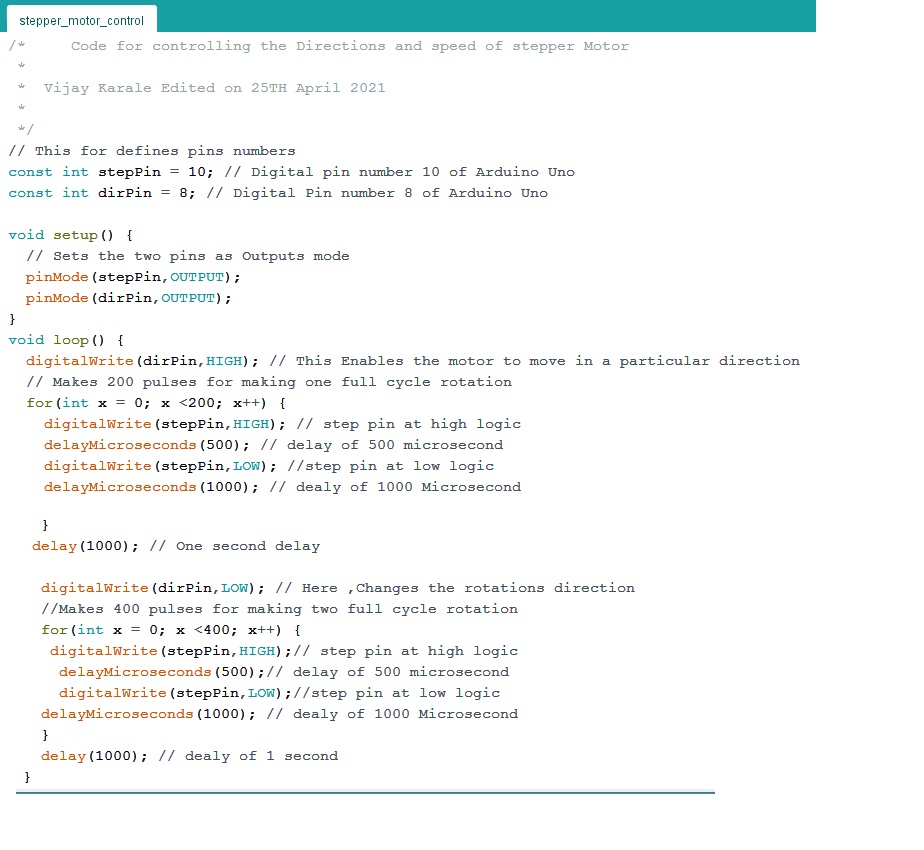
Here, The Source code of the Example
Vijay Karale Edited on 25TH April 2021 * */
// This for defines pins numbers
const int stepPin = 10; // Digital pin number 10 of Arduino Uno
const int dirPin = 8; // Digital Pin number 8 of Arduino Uno
void setup() {
// Sets the two pins as Outputs mode
pinMode(stepPin,OUTPUT);
pinMode(dirPin,OUTPUT);
}
void loop() {
digitalWrite(dirPin,HIGH); // This Enables the motor to move in a particular direction
// Makes 200 pulses for making one full cycle rotation
for(int x = 0; x <200; x++)
{
digitalWrite(stepPin,HIGH); // step pin at high logic
delayMicroseconds(500); // delay of 500 microsecond
digitalWrite(stepPin,LOW); //step pin at low logic
delayMicroseconds(1000); // dealy of 1000 Microsecond
} }
// delay(1000); // One second delay
digitalWrite(dirPin,LOW); // Here ,Changes the rotations direction
//Makes 400 pulses for making two full cycle rotation
for(int x = 0; x < 400; x++)
{
digitalWrite(stepPin,HIGH);// step pin at high logic
delayMicroseconds(500);// delay of 500 microsecond
digitalWrite(stepPin,LOW);//step pin at low logic
delayMicroseconds(1000); // dealy of 1000 Microsecond
}
delay(1000); // dealy of 1 second
}
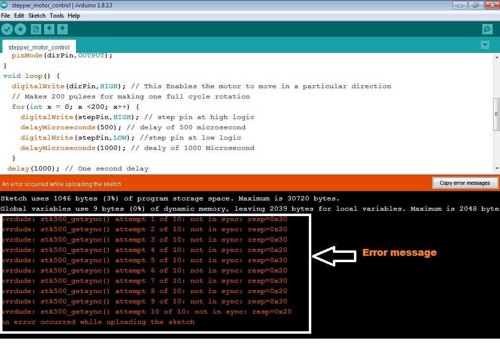
Here while uploading the code i have faced one problems its gives some error in Arduino IDE software "An error occurred while uploading the sketch
"
This is may be due to Arduino Uno Board was not plugged properly
In this case i had to unplug and again connect the plug propely USB Connections ,and finally i had to again upload the program now, gives the message uploading done
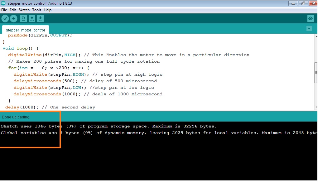
Now, the motor is running as per the given code with microcontroller Board.
The Video Shows Motor is running with A4899 Driver and Arduino Uno Board.
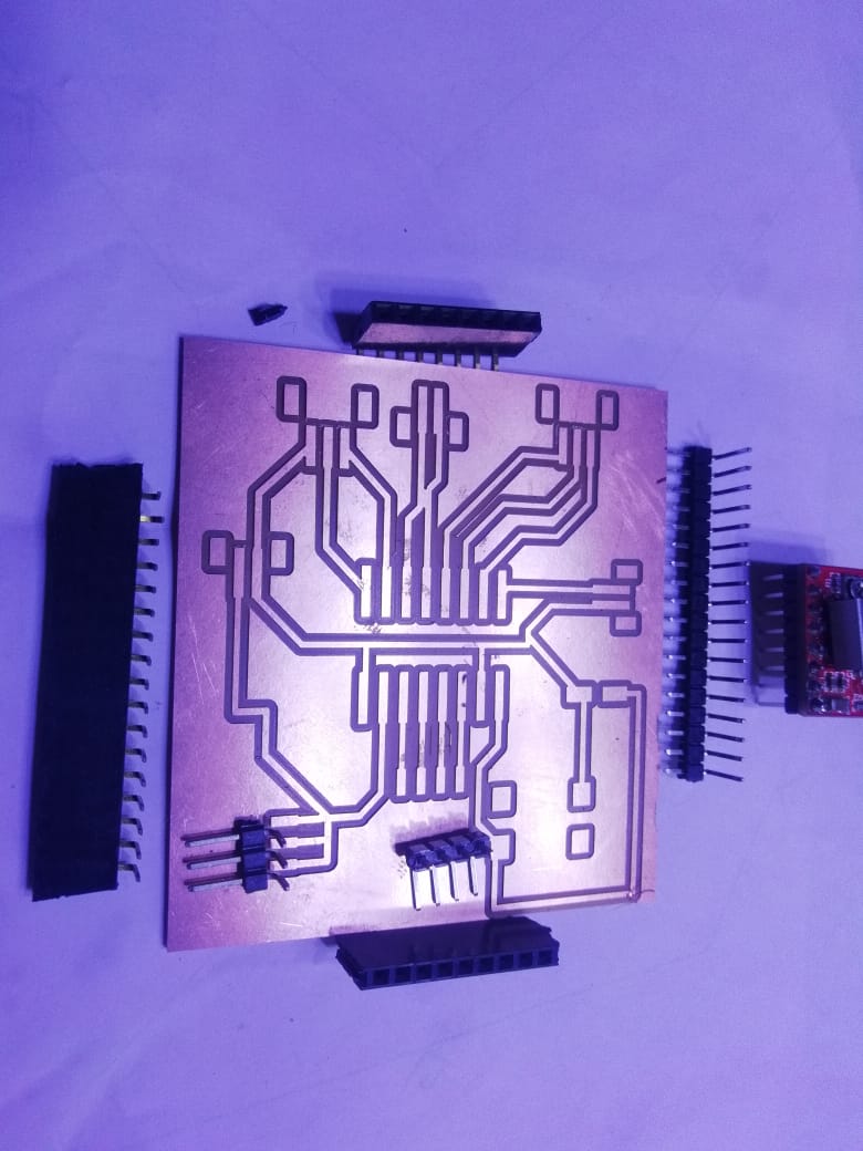
Desigining of A4988 Driver Sheild in EAGLE Software:
As I said for controlling the stepper motor with Microcontroller Board.So I have already designed the ATMEGA328P board in Input week so for this week i have to design the shield circuit for placing the drivers and connecting it to my board.
So, for designing the Driver Sheild Circuit I had to upadate some libraries like sparkfun connectors and A4988 footprint.
First I have download above said libraries and update in my EAGLE Software.
First, i have tried to design this board and milled it using SRM-20 Milling machine.
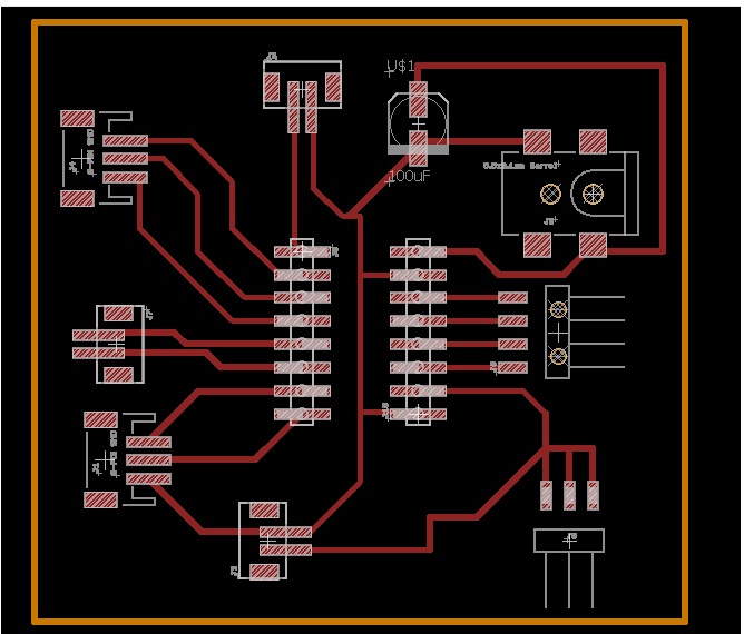
This is schematic designing for Sheild
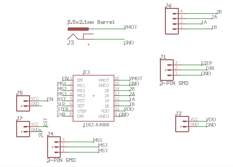
This is the board
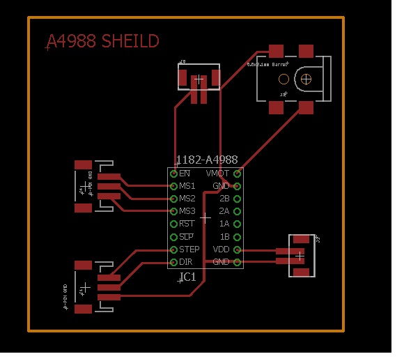
But, here I have faced problems while soldering the connector available in our lab not solder properly on this footprint which i have connected in designed the board. This is due to the padding is very small, So I was not able to connect the conneter over threre.
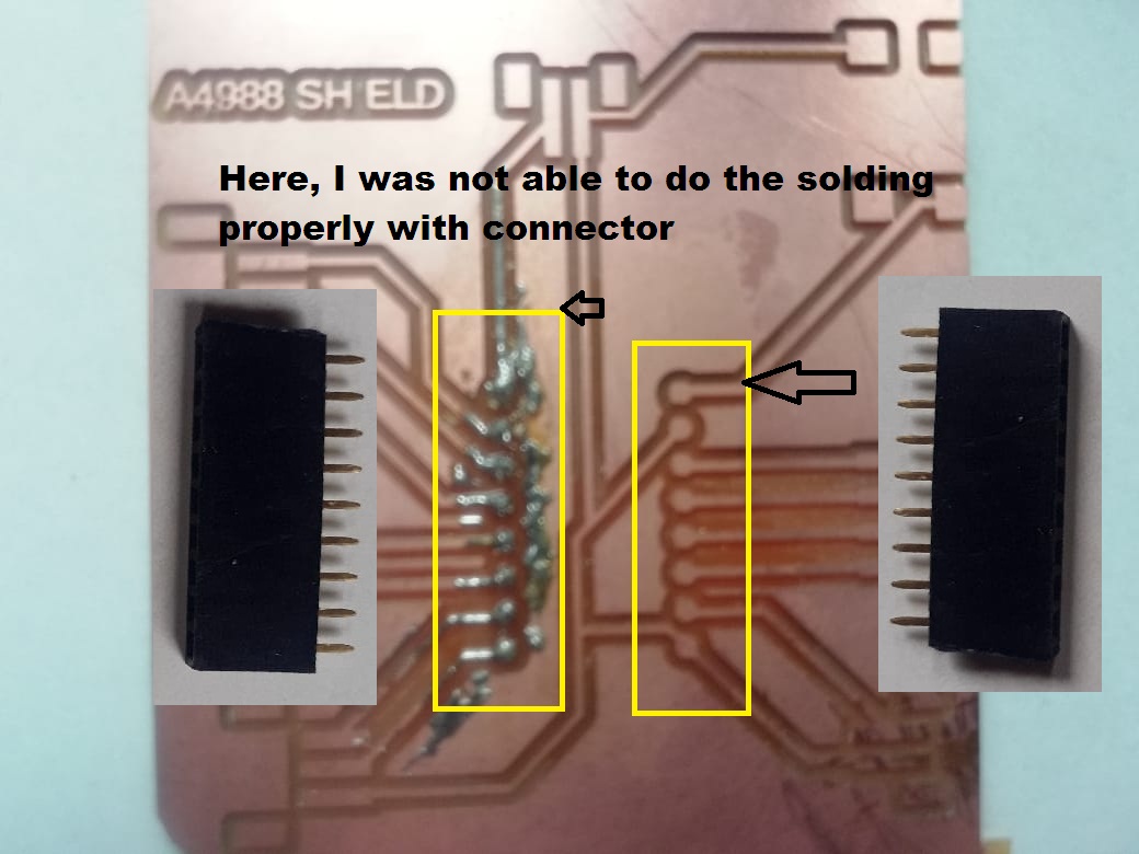
So I had to redesign the Board for selecting for proper connectors and considering padding distance of A4988 driver module
This is redesinging of Schematic
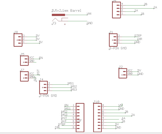
This routing of circuit by considering the distance and Padding of A4988 Driver Module
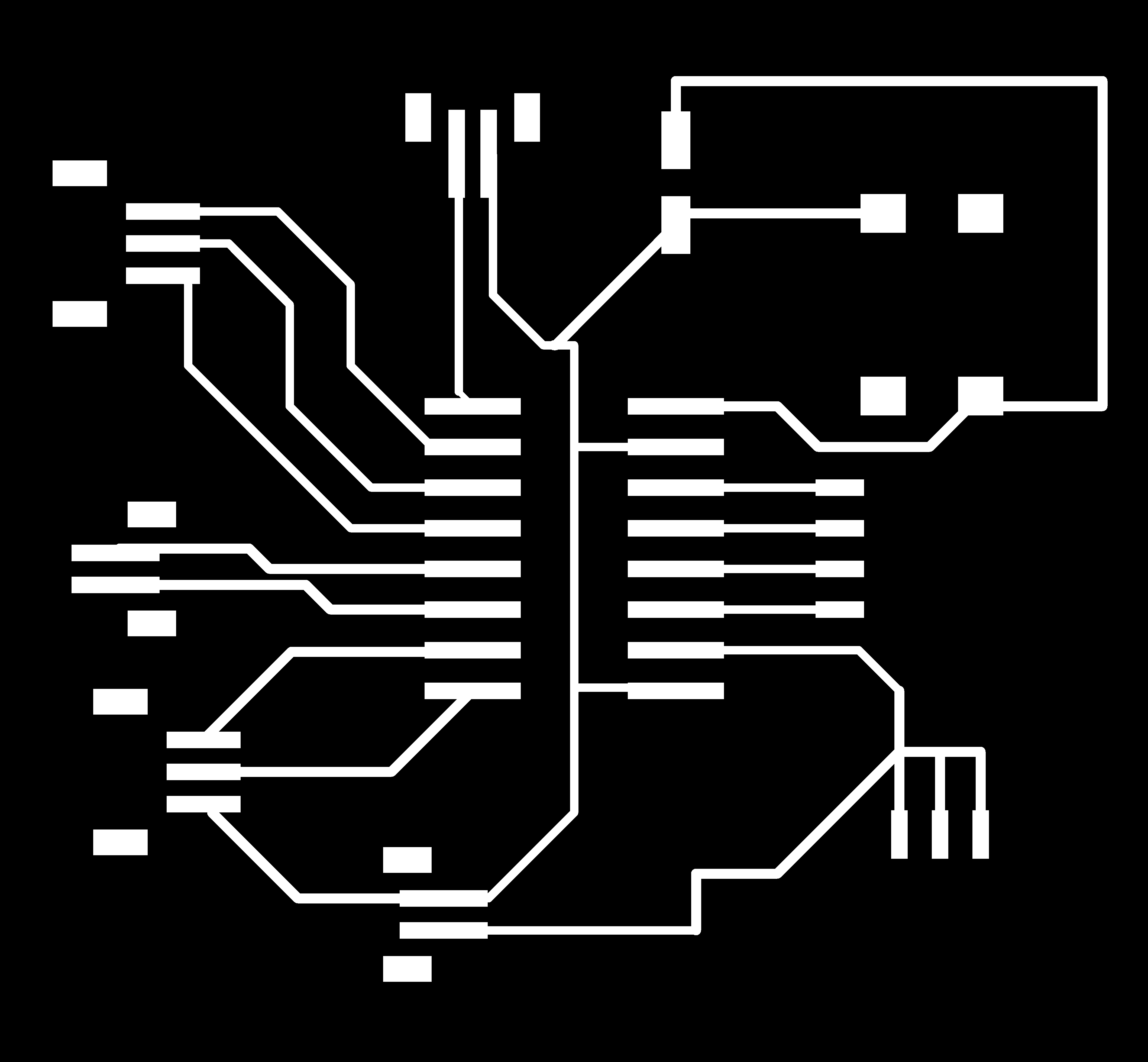
After routing is done i had to go for milling this board with SRM-20 machine. First I need to save the file in .png format both trace and cut and with the help of mods communate it with SRM Machine.
This is the PNG image of trace and cut

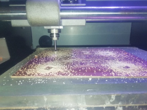
After that I need to give this file to mods software for milling of this board.
Then, Milling process is start
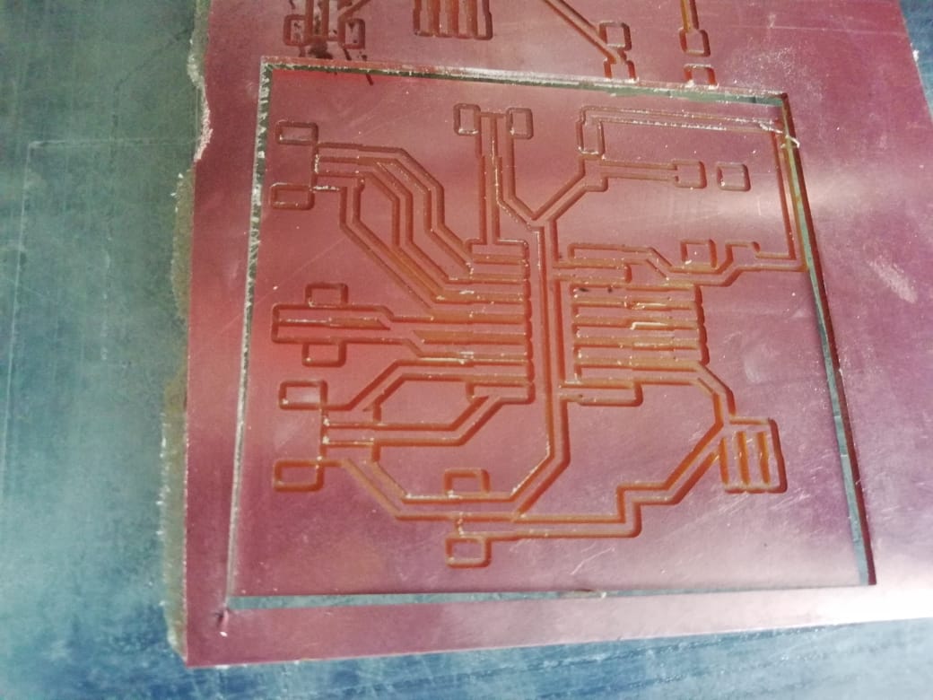
Here, I Select the component for soldering and start soldering to this board.
After soldering the board is ready now, I had to only connect the A4988 Driver.
Testing of stepper motor with A4988 Driver and Desinged ATMEGA328P Microcontroller Board.
So for testing of stepper motor with my designed boards firstly I have to do the proper connections with ATMEGA328P board and driver circuit, Here only I need 12v external power supply for powering the driver circuit. So i have used battery as source.
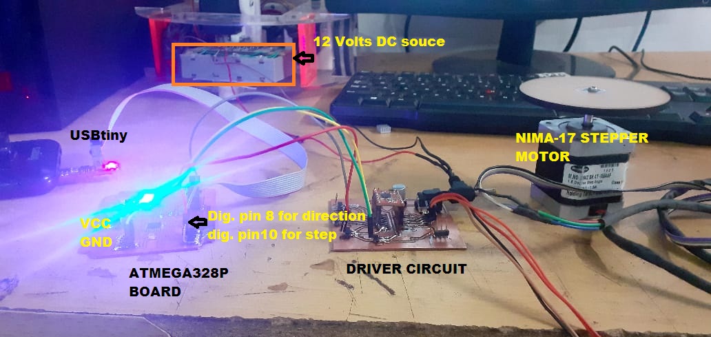
After connecting the circuit properly I had to run compile and upload the test code for controlling the stepper motor with the help of Arduino IDE software.
Here one thing should be remember that while uploading the code into the ATMEGA328P board we need to configure the Arduino IDE i.e Selecting the board from tool menu of Arduino IDE, Should select the board and programmer properly. i.e. Arduino nano Board and programmer will be USBtinyISP and then its shows the processor ATMEGA328P.
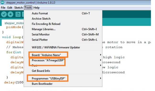
This is to avoid from the error messages while uploading any the code through ATMEGA328P Board.
Then, I have run the same code which i have test for Arduino Uno board
Here, In this code i have used two pins from ATMEGA328P Board i.e. Digital pin number 8 and 10 for controlling the directions and steps respectively, and others are VCC and GND.
and from driver side MS1,MS2,MS3 kept at low logic for full stepping mode, RESET and SLEEP are short, and winding connections given to the motor.
The Video Shows the Motor is running as per given code
Testing of 16*2 LCD display with my designed board ATMGA328P
About LCD Display
16*2 LCD Display with I2C module.
WHAT IS LCD 16 * 2?:-
An liquid-crystal display (LCD) is an electronic display module which uses liquid crystal to produce a visible image. The 16×2 LCD display is a very basic module commonly used in DIYs and circuits. The 16×2 translates o a display 16 characters per line in 2 such lines. In this LCD each character is displayed in a 5×7 pixel matrix. Electronicsforu
Features of 16*2 LCD display Module
-Operating Voltage is 4.7V to 5.3V
-Current consumption is 1mA without backlight
-Alphanumeric LCD display module, meaning can display alphabets and numbers
-Consists of two rows and each row can print 16 characters.
-Each character is build by a 5×8 pixel box
-Can work on both 8-bit and 4-bit mode
-It can also display any custom generated characters
-Available in Green and Blue Backlight
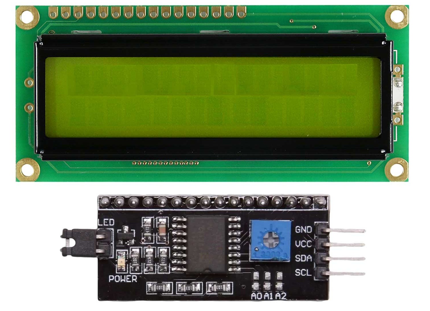
I2C LCD Adapter:-At the heart of the adapter is an 8-Bit I/O Expander chip – PCF8574. This chip converts the I2C data from an Arduino into the parallel data required by the LCD display.
This board also comes with a small trimpot to make fine adjustments to the contrast of the display.
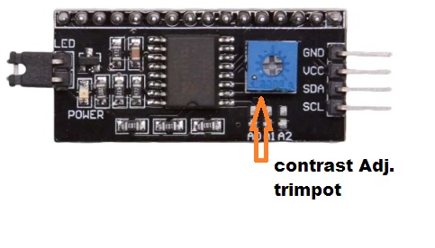
I2C module.
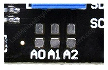
I2C Address of LCD
If you are using multiple devices on the same I2C bus, you may need to set a different I2C address for the board, so that it does not conflict with another I2C device.
To do so, the board has three solder jumpers (A0, A1 and A2) or solder pads
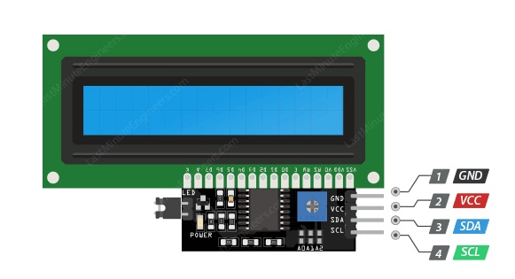
I2C LCD display Pinout
An I2C LCD has only 4 pins that interface it to the outside world. The connections are as follows:
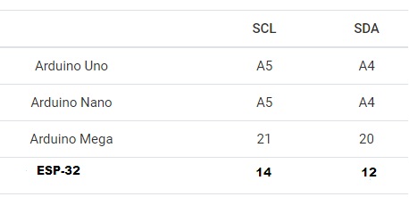
If you are using a different Arduino board, please refer below table.
For knowing the more detail of LCD Module I have reffered This Tutorial.
Then By following the above tutorial, I proceed my work on LCD display.
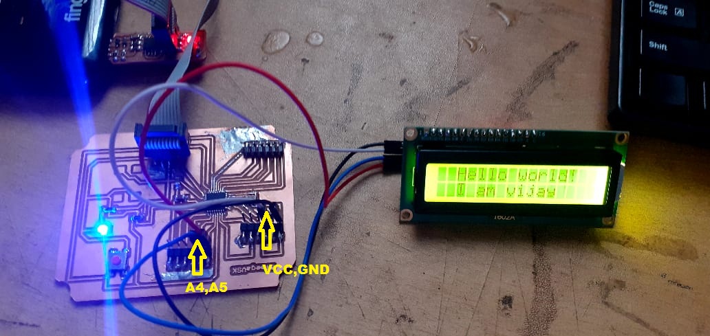
First, I have make the connections of lcd with ATmega328p Board as per circuit diagram.
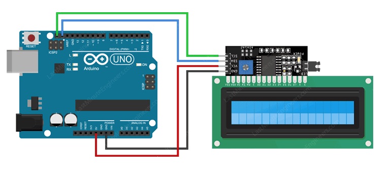
This shows the LCD Display connected to ATMEGA328P Board.
Once that is done, we can start the programming with LCD in Arduino IDE.
-Library Instalations:-
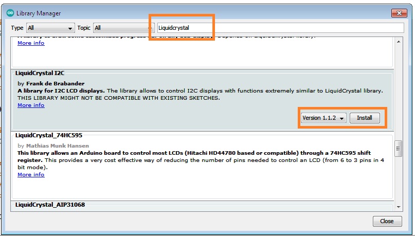
In order to interface the LCD and run the code we need to install the library called LiquidCrystal_I2C. This library is an improved version of the LiquidCrystal library that comes packaged with your Arduino IDE.
To install the library navigate to the Sketch > Include Library > Manage Libraries… Wait for Library Manager to download libraries index and update list of installed libraries.
Here, search by typing ‘liquidcrystal’. There should be a couple entries. Look for LiquidCrystal I2C library by Frank de Brabander. Click on that entry, and then select Install.
After insatlling the required libraies now next step is to determining the I2C address
So, by reffering the mentioned tutorial here, I used the same code to determine the I2C address by uplaading the skech on my Atmega328p Board.
Here I2C Address was Found. when I uploade this code
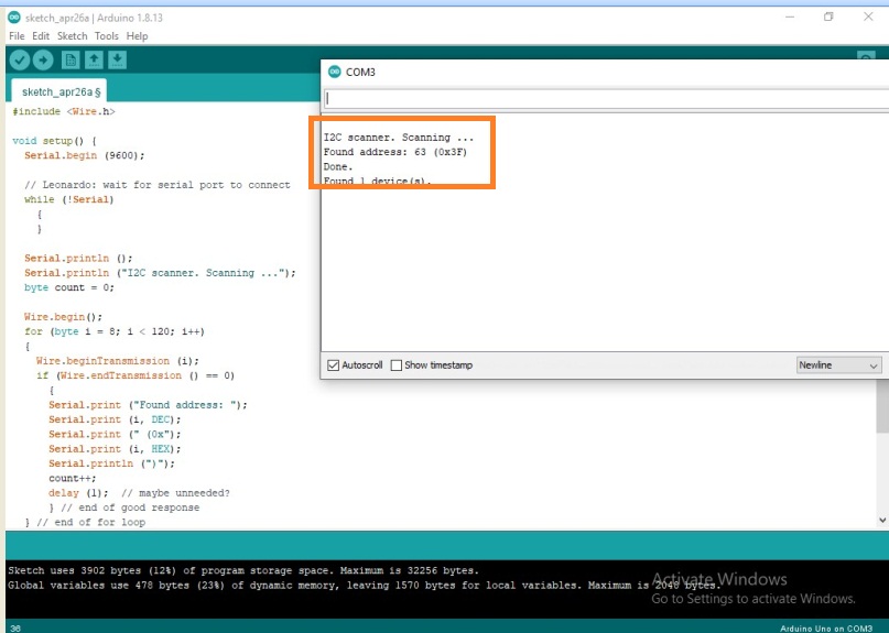
Code to find the I2C Adress.
#include( Wire.h )
void setup() {
Serial.begin (9600);
// Leonardo: wait for serial port to connect
while (!Serial)
{
}
Serial.println ();
Serial.println ("I2C scanner. Scanning ...");
byte count = 0;
Wire.begin();
for (byte i = 8; i < 120; i++)
{
Wire.beginTransmission (i);
if (Wire.endTransmission () == 0)
{
Serial.print ("Found address: ");
Serial.print (i, DEC);
Serial.print (" (0x");
Serial.print (i, HEX);
Serial.println (")");
count++;
delay (1); // maybe unneeded?
} // end of good response
} // end of for loop
Serial.println ("Done.");
Serial.print ("Found ");
Serial.print (count, DEC); Serial.println (" device(s).");
} // end of setup
void loop() {}
You’ll see the I2C address of your I2C LCD display.

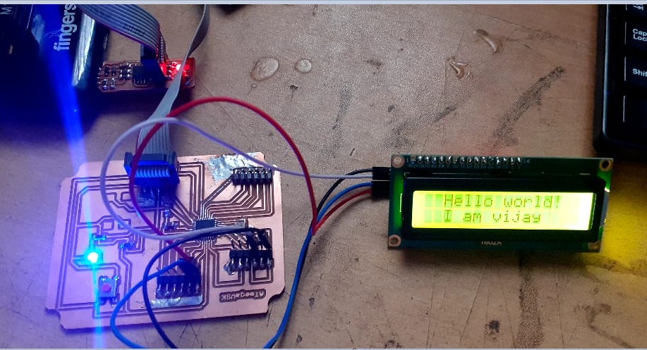
Then I have upload the test Simple code will print "Hello World" On first line and the in second line Print I am Vijay
Note:- But, before uploading the code, I need to make some changes to make it work for me. I need to enter the I2C address of your LCD and the dimensions of the display (columns and rows the display). If you are using 16×2 character LCD, pass the parameters 16 and 2
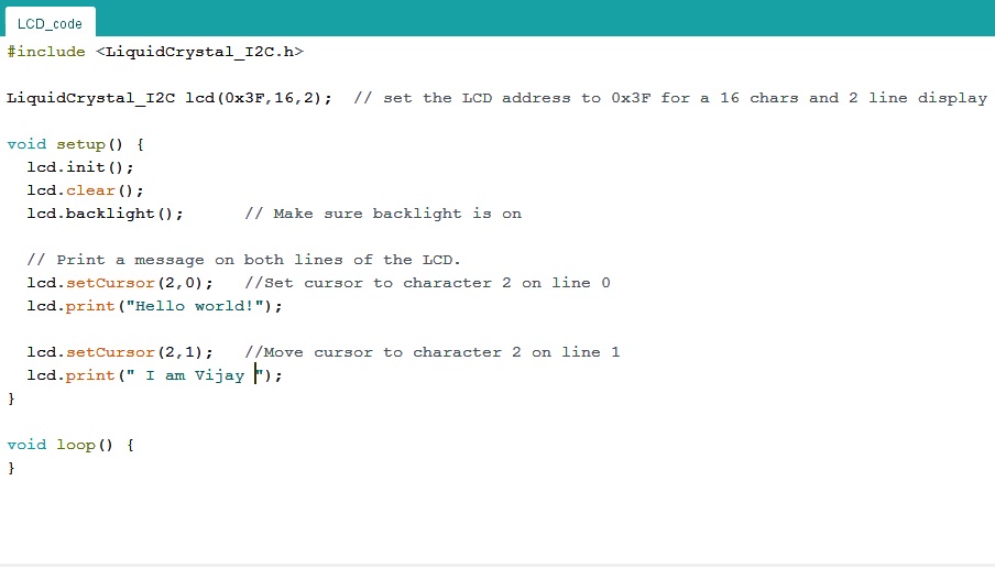
Code for printing the character on LCD Module.
Here, the same character Appear on LCD Dispaly.
Code For Display The Character on LCD display
#include (LiquidCrystal_I2C.h>
LiquidCrystal_I2C lcd(0x3F,16,2); // set the LCD address to 0x3F for a 16
chars and 2 line display
void setup() {
lcd.init();
lcd.clear();
lcd.backlight(); // Make sure backlight is on
// Print a message on both lines of the LCD.
lcd.setCursor(2,0); //Set cursor to character 2 on line 0
lcd.print("Hello world!");
lcd.setCursor(2,1); //Move cursor to character 2 on line 1
lcd.print(" I am Vijay ");
}
void loop() {
}
The Video Shows Displaying Character on LCD Module.
Learning Outcomes:-
I have learnt About the various Output Devices used in Electronics.
I have learnt about How to interface the Nima-17 Stepper Motor using Microcontroller Board.
I understood the designing of A4988 Sheild Circuit in Eagle Software.
I have learnt the working and interfacing of A4988 Stepper Motor Driver.
I have learnt about the interfacing of LCD Module with I2C to the Microntroller Board.
Finally, I have understood How to Measure the Power Consumption for various output devices.
DOWNLOAD's
Download my original file here