Task to be Perform for this week
1) Group Assignment
- Probe an input device's analog levels and digital signals
The task for the week is to probe an input device's analog levels and digital signals. For complitions of this task to measure the analog level and digital levels of various sensors that we are going to used in our Final projets i.e.
1) BME 280 (Temperature Humidity and Pressure)
2)BH 1750 (Light) Sensor.
3) PT 1000 Temperature sensor
4) Load cell with HX711 module and RFIF - MFRC522 Sensor.
we used above sensor is connected with oscilioscope for signal levels.
For more details about this assignment click here. GROUP ASSIGNMENT
2)Individual Assignment :
Design a microcontroller board.
Add a sensor to a microcontroller board that you have designed
Read the data from Sensors.
So, for my individual i have decided to test the various temperature sensor read the values using Serial Monitor's of arduino IDE.
1) I have designed the ATmega328 Microcontroller Board .
2) I have tested the different types of temperature the sensors becuase for accuracy and precision of the output i have used PT1000,DS18B20 Temperature Sensor,DHT11, NTC thermistor.
Learning outcomes
Demonstrate workflows used in sensing something with input device(s) and MCU board
Introduction about Input as a sensors (Source:Internet)
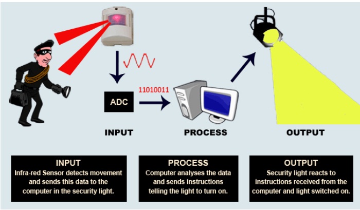
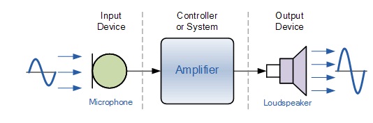
An input device responds to changes in the environment and produces a suitable electrical signal for processing in an electronic circuit. In all input devices, other forms of energy are transformed into electrical energy.The sensor is an element that produces signals relating to the quantity that is being measured. According to Instrument Society of America, “a sensor is a device that provides usable output in response to a specified quantity which is measured.” The word sensor is derived from the original meaning ‘to perceive.’
Sensors are devices that perform input function in a system as they ‘sense’ the changes in a quantity. The best example of a sensor is mercury thermometer. Here the quantity that is being measured is heat or temperature. The measured temperature is converted to a readable value on the calibrated glass tube, based on the expansion and contraction of liquid mercury.
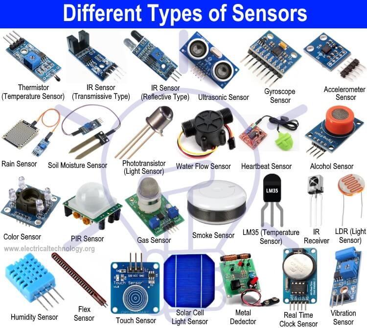
The world is full of sensors. In our day-to-day life, we come across automation in all the activities. Automation includes turning on lights and fans using mobile phones, controlling TV using mobile apps, adjusting the room temperature, smoke detectors, etc. All these are done with help of sensors. These days, any embedded system based product has inbuilt sensors in it. There are many applications like Mobile controlled CCTV camera, weather monitoring and prediction apps, etc. Sensors play a very vital role in Healthcare monitoring and detection. Therefore, before building an application-using sensor, we must understand what exactly does a sensor do and how many types of sensors are available.
What is a Sensor?
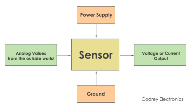
A sensor is defined as a device or a module that helps to detect any changes in physical quantity like pressure, force or electrical quantity like current or any other form of energy. After observing the changes, sensor sends the detected input to a microcontroller or microprocessors
This is how sensors work
About temperature sensors
Basic block Diagram of temperature sensors
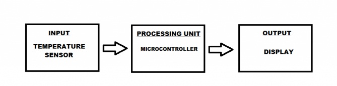
A temperature sensor is an electronic device that measures the temperature of its environment and converts the input data into electronic data to record, monitor, or signal temperature changes. There are many different types of temperature sensors. Some temperature sensors require direct contact with the physical object that is being monitored (contact temperature sensors), while others indirectly measure the temperature of an object (non-contact temperature sensors).
Non-contact temperature sensors are usually infrared (IR) sensors. They remotely detect the IR energy emitted by an object and send a signal to a calibrated electronic circuit that determines the object's temperature. For more detail i have rerrefed this link
Source
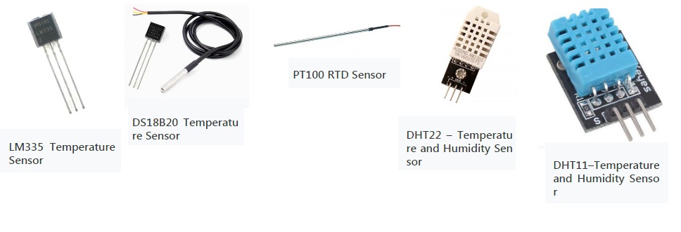
Different Types of temperature Sensors
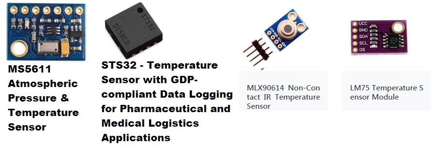
(In My Random Generator presentation Prof. Neil Suggest me, For my Final Project mlx90614 infrared temperature sensor can use.)
Each application may have a different temperature sensing need. The differences include what is being measured (air, mass, or liquid), where it is being measured (inside or outside), and the range of temperature being measured. There are four types of temperature sensors that are most commonly used in modern-day electronics: thermocouples, RTDs (resistance temperature detectors), thermistors, and semiconductor based integrated circuits (IC).
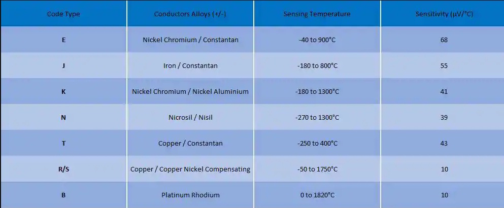
1) Thermocouples:-
Thermocouples are the most commonly used type of temperature sensor. They are used in industrial, automotive, and consumer applications. Thermocouples are self-powered, require no excitation, can operate over a wide temperature range, and have quick response times.
There are several types of thermocouples that are made from a variety of different material, which allows for different temperature ranges and different sensitivities. The different types are differentiated by designated letters. The most commonly used is the K type. Table 1 shows characteristics of a few common types of thermocouples.
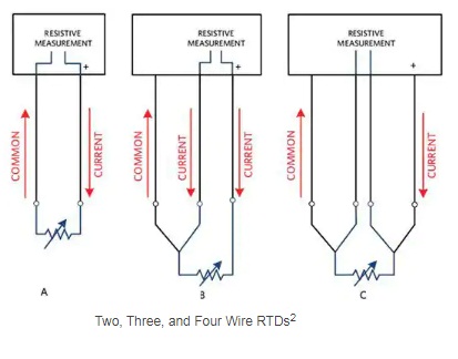
2) RTD (Resistance Temperature Detector):-
As temperature changes, the resistance of any metal changes as well. This difference in resistance is what RTD temperature sensors are based on. An RTD is a resistor with well-defined resistance vs. temperature characteristics. Platinum is the most common and accurate material used to make RTDs
Platinum RTDs are also referred to as PRTDs. They are often available with a 100 Ω and 1000 Ω resistance at 0°C. They are referred to as PT100 and PT1000 respectively.
Platinum RTDs are used because they offer a near linear response to temperature changes, they are stable and accurate, they provide repeatable responses, and they have a wide temperature range. RTDs are often used in precision applications because of their accuracy and repeatability.
3) Thermistors
Thermistors are similar to RTDs in that temperature changes cause measurable resistance changes. Thermistors are usually made from a polymer or ceramic material. In most cases, thermistors are cheaper but are also less accurate than RTDs. Most thermistors are available in two wire configurations.
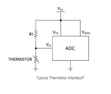
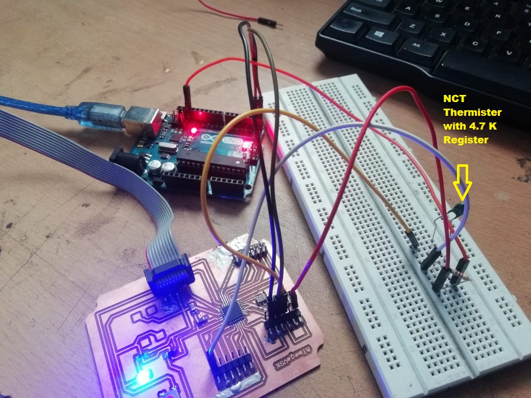
The NTC (Negative Temperature Coefficient) thermistor is the most commonly used thermistor for temperature measurement application. An NTC thermistor’s resistance decreases as the temperature increases. Thermistors have a non-linear temperature resistance relationship. This requires a significant correction to interpret the data correctly. A common approach of using a thermistor, shown in Figure, is where a thermistor and a fixed value resistor form a voltage divider with an output that is digitized by an ADC.
Semiconductor based ICs
Semiconductor based temperature sensor ICs come in two different types: local temperature sensor and remote digital temperature sensor. Local temperature sensors are ICs that measure their own die temperature by using the physical properties of a transistor. Remote digital temperature sensors measure the temperature of an external transistor.
For e.g. Diode as a temperature sensors
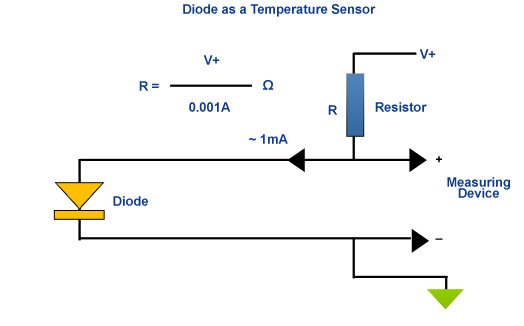
Local temperature sensors can use either analog or digital outputs. Analog outputs can be either voltage or current while digital outputs can be seen in several formats such as I²C, SMBus, 1-Wire®, and Serial Peripheral Interface (SPI). Local temperature sensors sense the temperature on printed circuit boards or the ambient air around it. The MAX31875 is an extremely small local temperature sensor and can be used in multiple applications including battery powered applications.
My Final project is, Edible oil temperature controller , for that I have to measure the temperature of frying oil.
As per survey For good fry the maximum oil temperature of any food is in range the of 350 F to 375 F i.e 150 Degree Celcius to 170 Degree Celcius,
So i required to use the temperature sensor which can measure the temperature of oil upto 200 Degree Celcius
For this week of Assignment i have tested the different temperature sensor
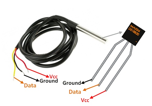
1. About DS18B20 Temperature Sensor
The DS18B20 is a 1-wire programmable Temperature sensor from maxim integrated. It is widely used to measure temperature in hard environments like in chemical solutions, mines or soil etc. The constriction of the sensor is rugged and also can be purchased with a waterproof option making the mounting process easy. It can measure a wide range of temperature from -55°C to +125° with a decent accuracy of ±5°C. Each sensor has a unique address and requires only one pin of the MCU to transfer data so it a very good choice for measuring temperature at multiple points without compromising much of your digital pins on the microcontroller.
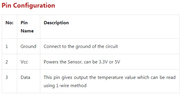
DS18B20 Sensor Specifications
Programmable Digital Temperature Sensor
Communicates using 1-Wire method
Operating voltage: 3V to 5V
Temperature Range: -55°C to +125°C
Accuracy: ±0.5°C
Output Resolution: 9-bit to 12-bit (programmable)
Unique 64-bit address enables multiplexing
time: 750ms at 12-bit
Programmable alarm options
Available as To-92, SOP and even as a waterproof sensor
To know the more detail about this sensors i have read the datasheet DS18B20 DATASHEET
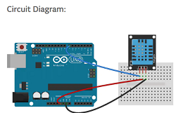
Connections between Arduino Uno and Multiple DS18B20 Temperature Sensor
Testing of DS18B20 Sensor
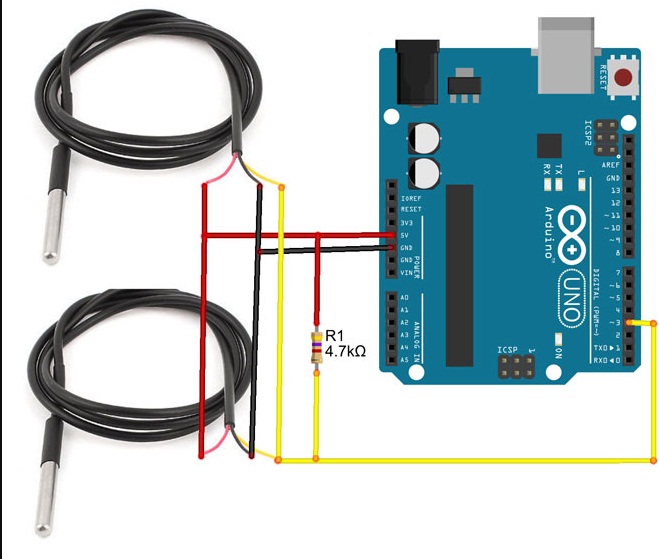
For tesing purpose this is how i made the circuit connection and sensors is inserted in water and run the code at this time the room temperature is near about 30 degree celcius so here i have checked the tempture of water, so it shows that reduce in temperature.
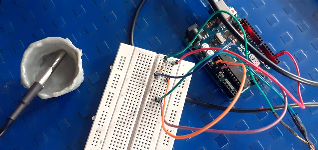
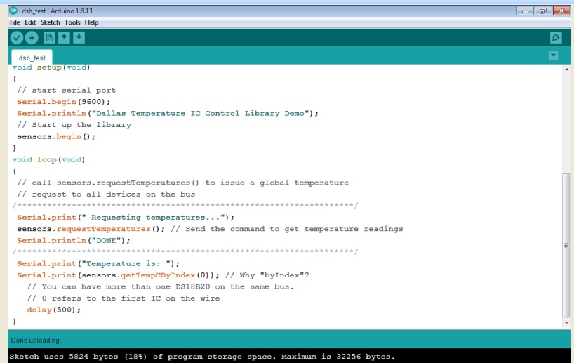
Here, I have run the test code with arduino uno microcontroller Board
Here showing the reduced in room temperature i.e. 27 to 28 degree celcius
2. About PT1000 temperature Sensor
Basics about PT1000
The PT1000 is a PTC resistor. This in turn means that the internal resistance increases with increasing temperature. PT100/PT1000 are very popular in industry because these temperature sensors provide very accurate measurement results, have a long life and can also be replaced very easy. Another advantage of these sensors is their linearity. This means that the output voltage of the transducer circuit behaves quite linearly throughout and can be processed by the microcontroller without complex mathematical formulas.
For knowing more detail about this sensor i have reffered this LINK
This above temperature sensor, i am using for my final project for prototype developement because i need the maximum range of temperature for my project is about 200 degree Celcius.
So, this Pt1000 sensors are the second most common type of platinum resistance thermometer.
Often resistance thermometers are generally called Pt1000 sensors, even though in reality they may not be the Pt1000 type. Pt refers to that the sensor is made from Platinum (Pt). 1000 refers to that at 0°C sensor has a resistance of 1000 ohms (Ω). Pt1000 sensors are used over Pt100 sensors in two wire applications as Pt1000s make lead resistance less significant.
For this perticular type of sensor i need to do the calibration of PT1000 Module. so for calibration of this sensor I took Thermameter and put into the Electric Kettle for measuring the temperature of water. So for calibrate my sensor i put both the module thermameter and temperature sensor into the electric kettle.
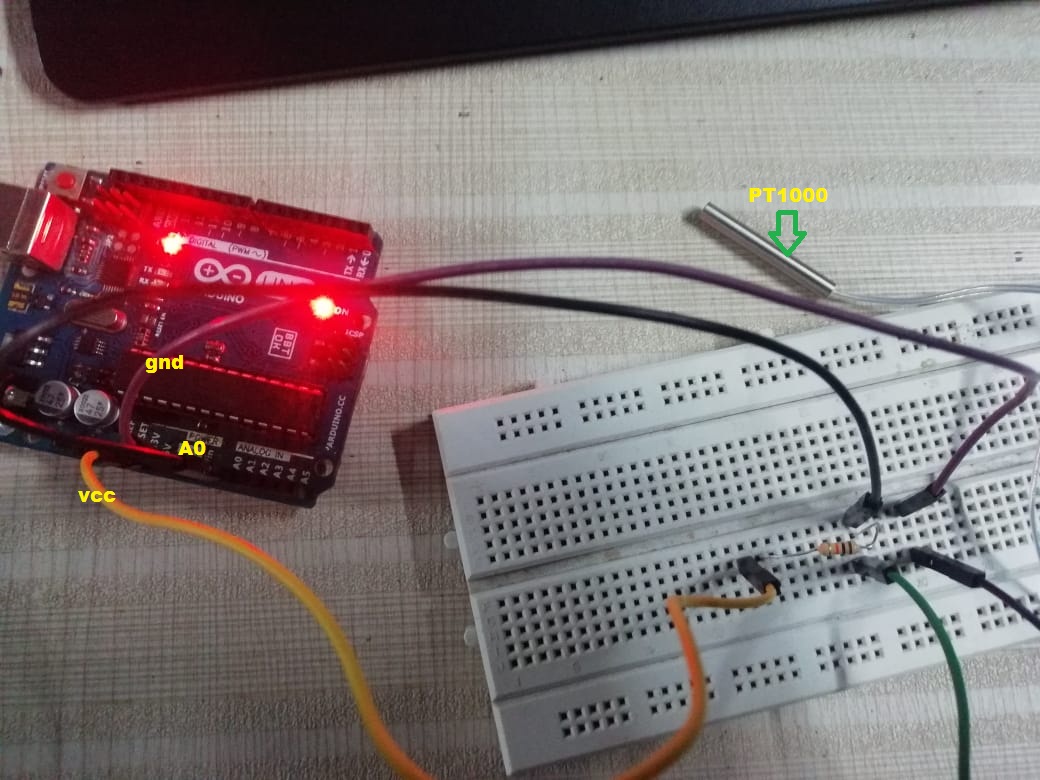
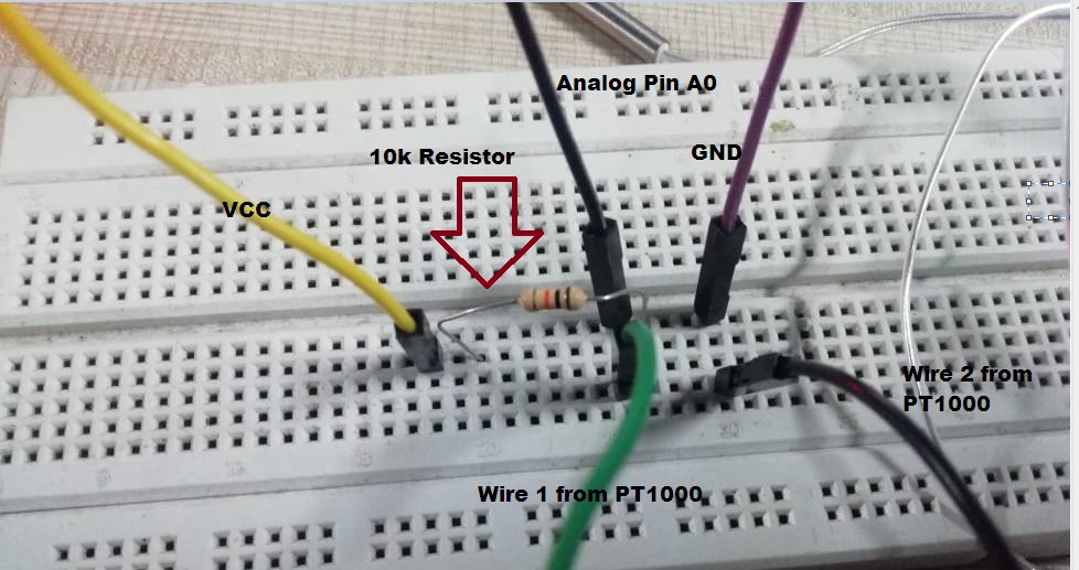
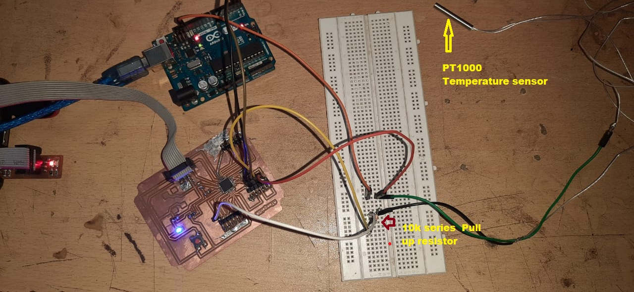
Then make the connection of PT1000 with arduino UNO board. I have set up a voltage divider circuit connected to an Arduino uno at the 5V and gnd.
The PT1000 temp sensor, analog pin 0, and a 10kOhm resistor in series.
Then i have understand first what is the actually voltage divider rule.
The Image shows the voltage devider rule the voltage applied from the source that can be divided into the resitances are connected in series i.e. will get the voltage drop across each resitance.
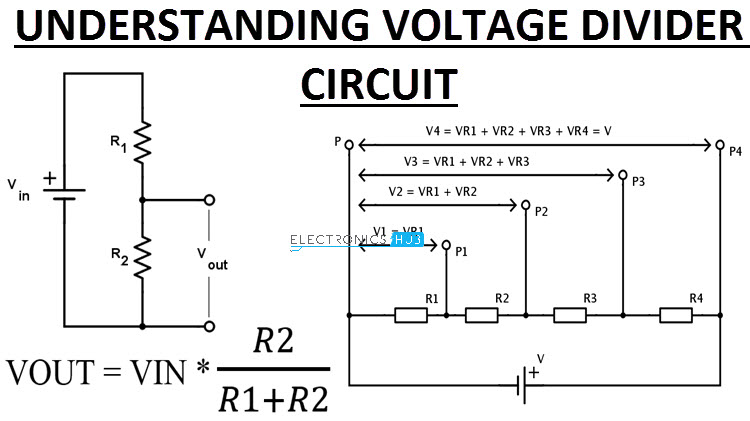
Here we need to convert what ever the Resistance of PT1000 into Voltage value for calibration.However, since you cannot measure resistance with a microcontroller, but only analog voltages, a corresponding converter is needed. The simplest converter is a classic voltage divider.
For this, we have to connect the resistor with a fixed known value i.e suppose 10k, is connected in series to the PT1000. In the middle of the two resistors the voltage can be measured, which changes depending on the temperature at the PT1000. Since the PT1000 itself could heat up due to a too high current, the second resistor must be correspondingly high. 10 kiloohm is a good compromise between voltage and current for this application. In addition, with a 10 kiloohm resistor in series to the PT1000 at 0 degrees Celsius, you have about 1/10 of the operating voltage as measuring voltage. This is I have reffered from the This Tutorial.
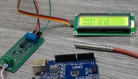
This is how I have made the connection with PT1000
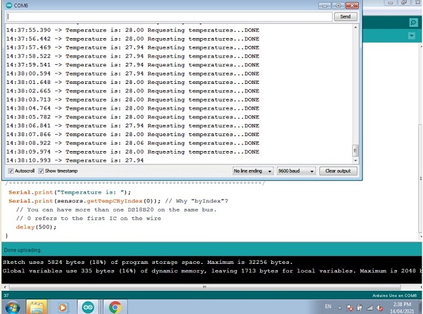
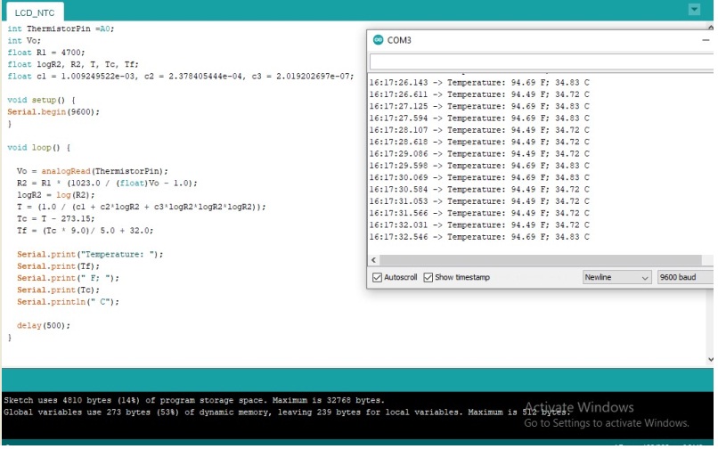
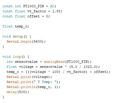
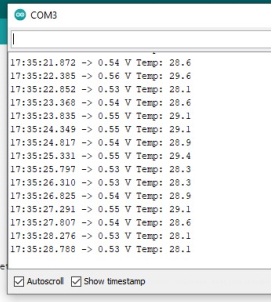
Then, I have uploaded the calibrated code.the serial monitor of arduino IDE Showing this Kind of reading.
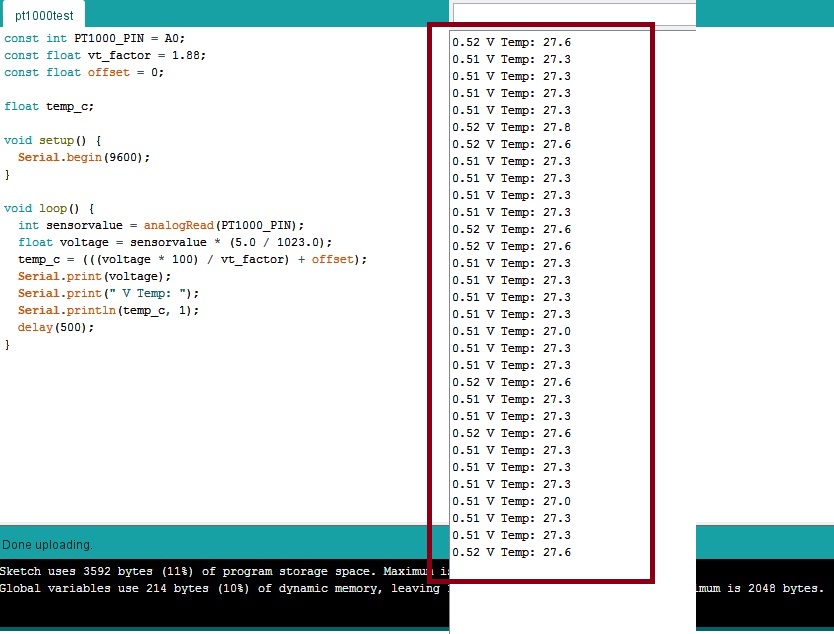
Here the values which are showing on serial monitor some what appox. the room tempreture but I need to calibrate this sensor for more accuracy, Means I will get the precise reading from PT1000
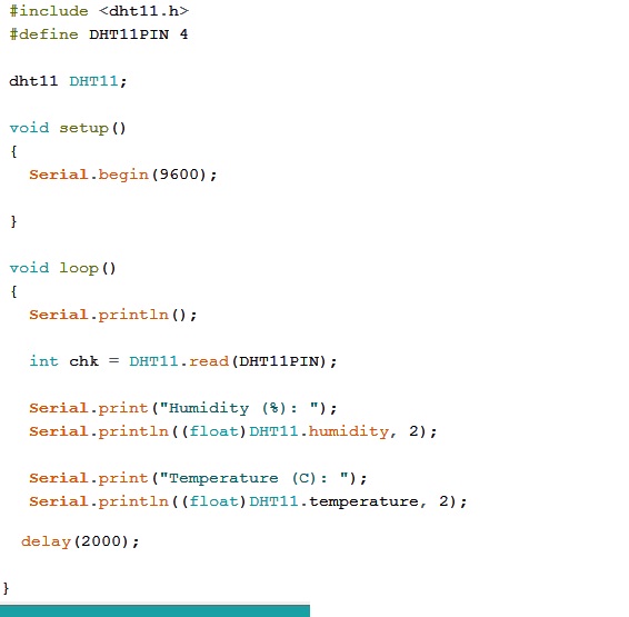
3.About DHT11 temperature Sensors
The DHT11 is a basic, ultra low-cost digital temperature and humidity sensor. It uses a capacitive humidity sensor and a thermistor to measure the surrounding air, and spits out a digital signal on the data pin (no analog input pins needed). Its fairly simple to use, but requires careful timing to grab data. You can get new data from it once every 2 seconds, so when using the library from Adafruit, sensor readings can be up to 2 seconds old.
Comes with a 4.7K or 10K resistor, which you will want to use as a pullup from the data pin to VCC.
Specifications:
3 to 5V power and I/O
2.5mA max current use during conversion (while requesting data)
Good for 20-80% humidity readings with 5% accuracy
Good for 0-50 °C temperature readings +-2 °C accuracy
No more than 1 Hz sampling rate (once every second)
Body size 15.5mm x 12mm x 5.5mm
4 pins with 0.1" spacing
After knowing the detail of this sensor i have worked on this to measure the temperature readings.
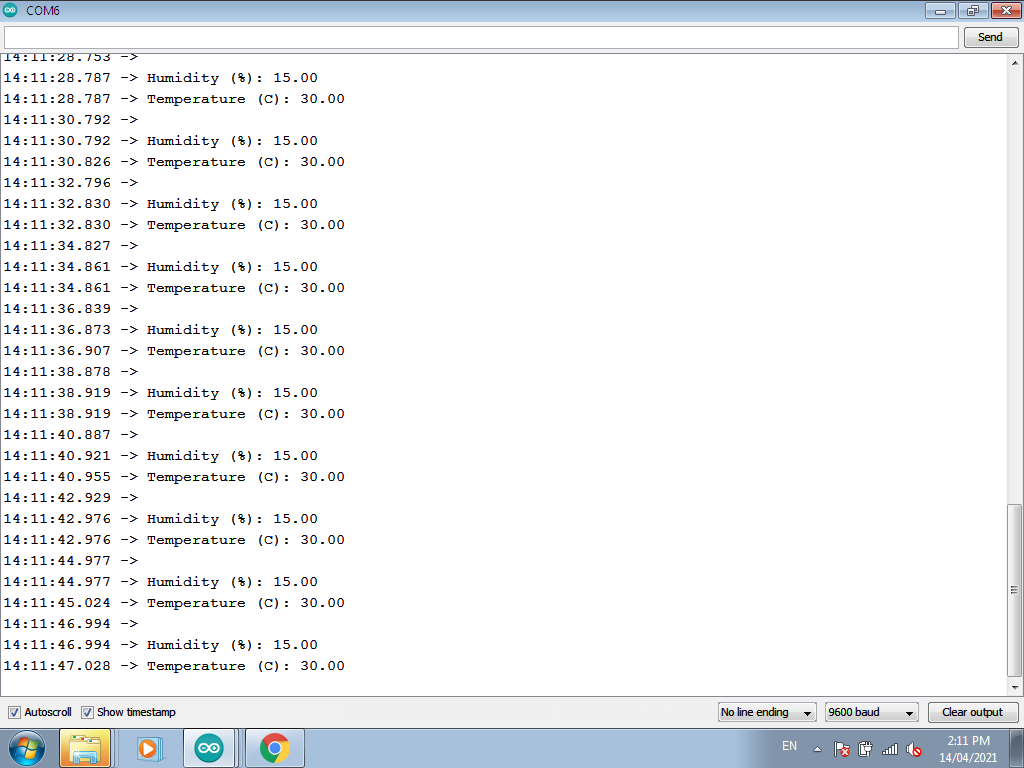
by following this I have done the connection and run the code, Initially its gives some error for reading but finally serial monitor gives the reading of room temperature 30 degree Celcius and humidity also.
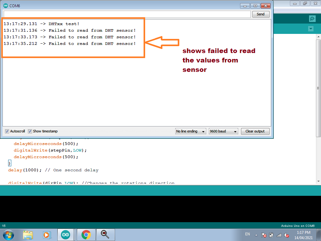
This is because of loose connections, so I have checked again and then getting the acurate values on serial monitor of Arduino IDE.
About Atmega328P Board Design
After understsnding about temperature sensors like DS18B20,PT1000,DHT11 and others now the next work is to know about the another family of AVR microcontroller i.e. ATmega328p.
What is the use of microcontroller?
A Microcontroller (μC or uC) is a solitary chip microcomputer fabricated from VLSI fabrication. A micro controller is also known as embedded controller. Today various types of microcontrollers are available in market with different word lengths such as 4bit, 8bit, 64bit and 128bit microcontrollers. Microcontroller is a compressed micro computer manufactured to control the functions of embedded systems in office machines, robots, home appliances, motor vehicles, and a number of other gadgets. A microcontroller is comprises components like - memory, peripherals and most importantly a processor. Microcontrollers are basically employed in devices that need a degree of control to be ap plied by the user of the device.
To know more deatails about this DATASHEET
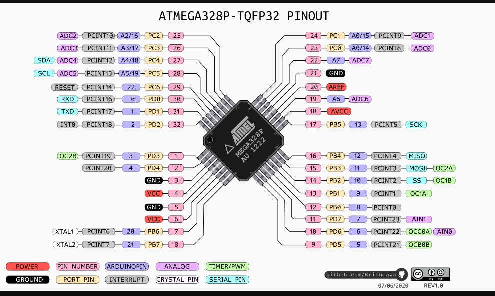
Introduction About Atmega328P:-
The ATmega328P is a single-chip microcontroller created by Atmel in the megaAVR family (later Microchip Technology acquired Atmel in 2016). It has a modified Harvard architecture 8-bit RISC processor core.
The high-performance, low-power Microchip AVR RISC-based CMOS 8-bit microcontroller combines 4KB ISP flash memory, 256-Byte EEPROM, 256B SRAM, 12 general purpose I/O lines, 32 general purpose working registers, an 8-bit timer/counter with two PWM channels, a 16-bit timer/counter with two PWM channels, internal and external interrupts, an 8-channel 10-bit A/D converter, a programmable gain stage (1x, 20x) for 12 differential ADC channel pairs, programmable watchdog timer with internal oscillator, a internal calibrated oscillator, and three software selectable power saving modes. By executing powerful instructions in a single clock cycle, the device achieves throughputs approaching 1 MIPS per MHz, balancing power consumption and processing speed.
Features
|
ATMEGA328P – Simplified Features |
|
|
CPU |
8-bit AVR |
|
Number of Pins |
28 |
|
Operating Voltage (V) |
+1.8 V TO +5.5V |
|
Number of programmable I/O lines |
23 |
|
Communication Interface |
Master/Slave SPI Serial Interface(17,18,19 PINS) [Can be used for programming this controller] Programmable Serial USART(2,3 PINS) [Can be used for programming this controller] Two-wire Serial Interface(27,28 PINS)[Can be used to connect peripheral devices like Servos, sensors and memory devices] |
|
JTAG Interface |
Not available |
|
ADC Module |
6channels, 10-bit resolution ADC |
|
Timer Module |
Two 8-bit counters with Separate Prescaler and compare mode, One 16-bit counter with Separate Prescaler,compare mode and capture mode. |
|
Analog Comparators |
1(12,13 PINSp> |
|
DAC Module |
Nil |
|
PWM channels |
6 |
|
External Oscillator |
0-4MHz @ 1.8V to 5.5V 0-10MHz @ 2.7V to 5.5V 0-20MHz @ 4.5V to 5.5V |
|
Internal Oscillator |
8MHz Calibrated Internal Oscillator |
|
Program Memory Type |
Flash |
|
Program Memory or Flash memory |
32Kbytes[10000 write/erase cycles] |
|
CPU Speed |
1MIPS for 1MHz |
|
RAM |
2Kbytes Internal SRAM |
|
EEPROM |
1Kbytes EEPROM |
|
Watchdog Timer |
Programmable Watchdog Timer with Separate On-chipOscillator |
|
Program Lock |
Yes |
|
Power Save Modes |
Six Modes[Idle, ADC Noise Reduction, Power-save, Power-down, Standby and Extended Standby] |
|
Operating Temperature |
-40°C to +105°C(+105 being absolute maximum, -40 being absolute minimum) |
Schematic and Board of ATMEGA328P Designing in EAGLE
After Understanding the Role of microcontroller for Input devices I had to design the schematic and board design in eagle software here first I have already updated all the libraries which was required for designing the ATMEGA328P.
For Designing this Board considering the my final project requirement, as i am using one temperature sensor,Steppper motor, ESP8266 Wifi module, and Oled display. So following above device i had design my board.
I tried to have AVR ISP header pins ,FTDI headres ,Crystal oscillators reset buttons and one led.After having this some pins are left out for that i used one pin heder so that i can used these pins later.
Schemetic
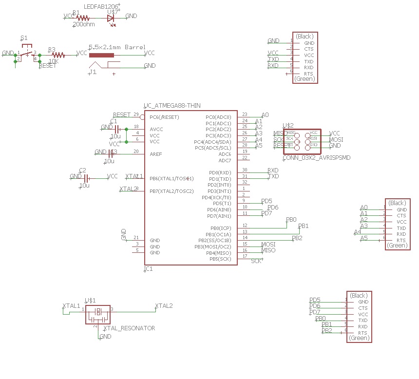
Considering the requirement of my final project I had design this schematic
After completing schematic part I had to switch on board i.e. routing part, There was i have faced sone problems while routing this board the vias was not getting completaly zero and DRC gives some errors in board.
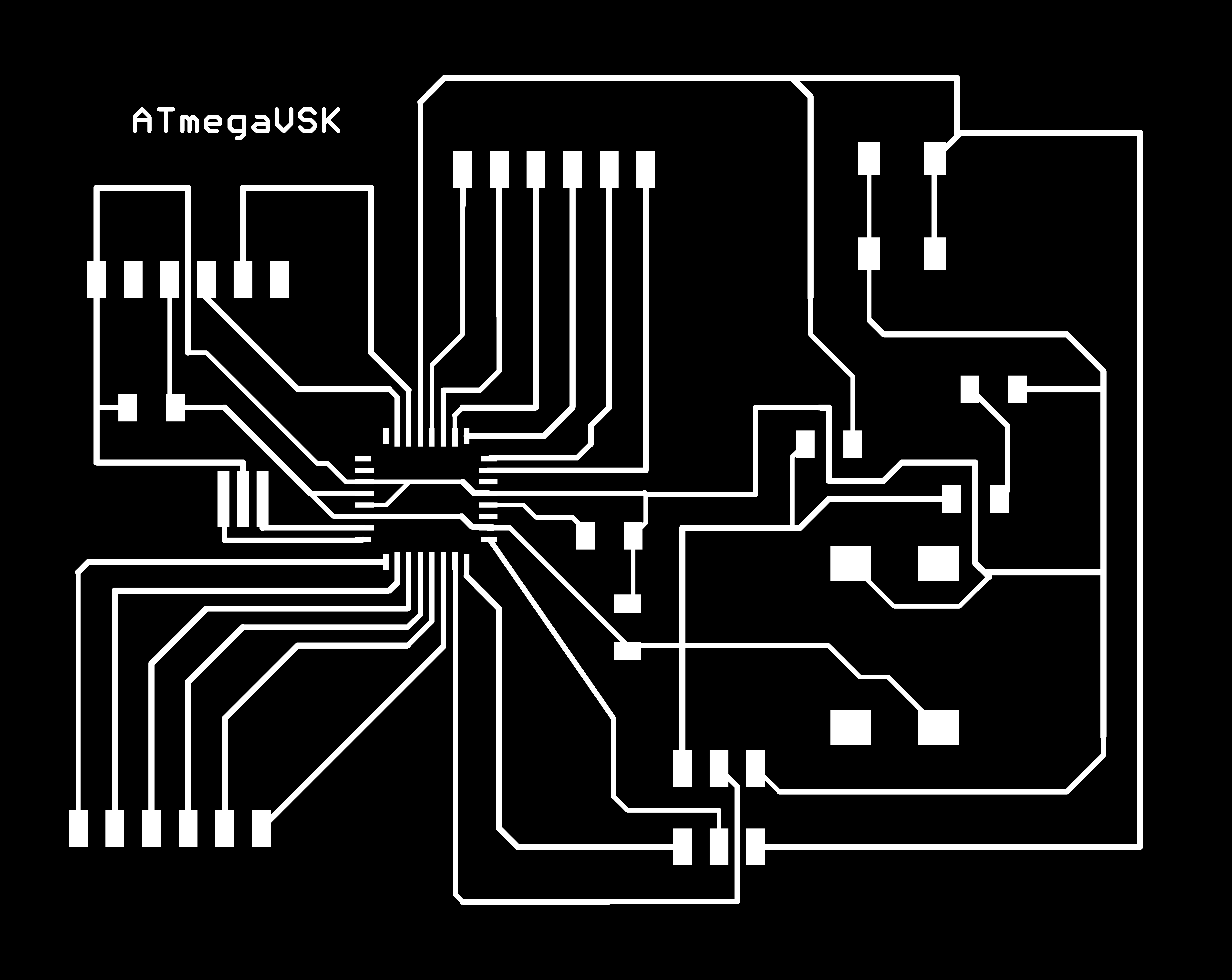
so after some troubleshooting I have got the results. and my final routing is as shown.
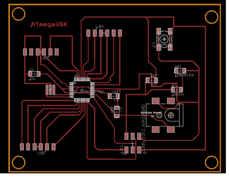
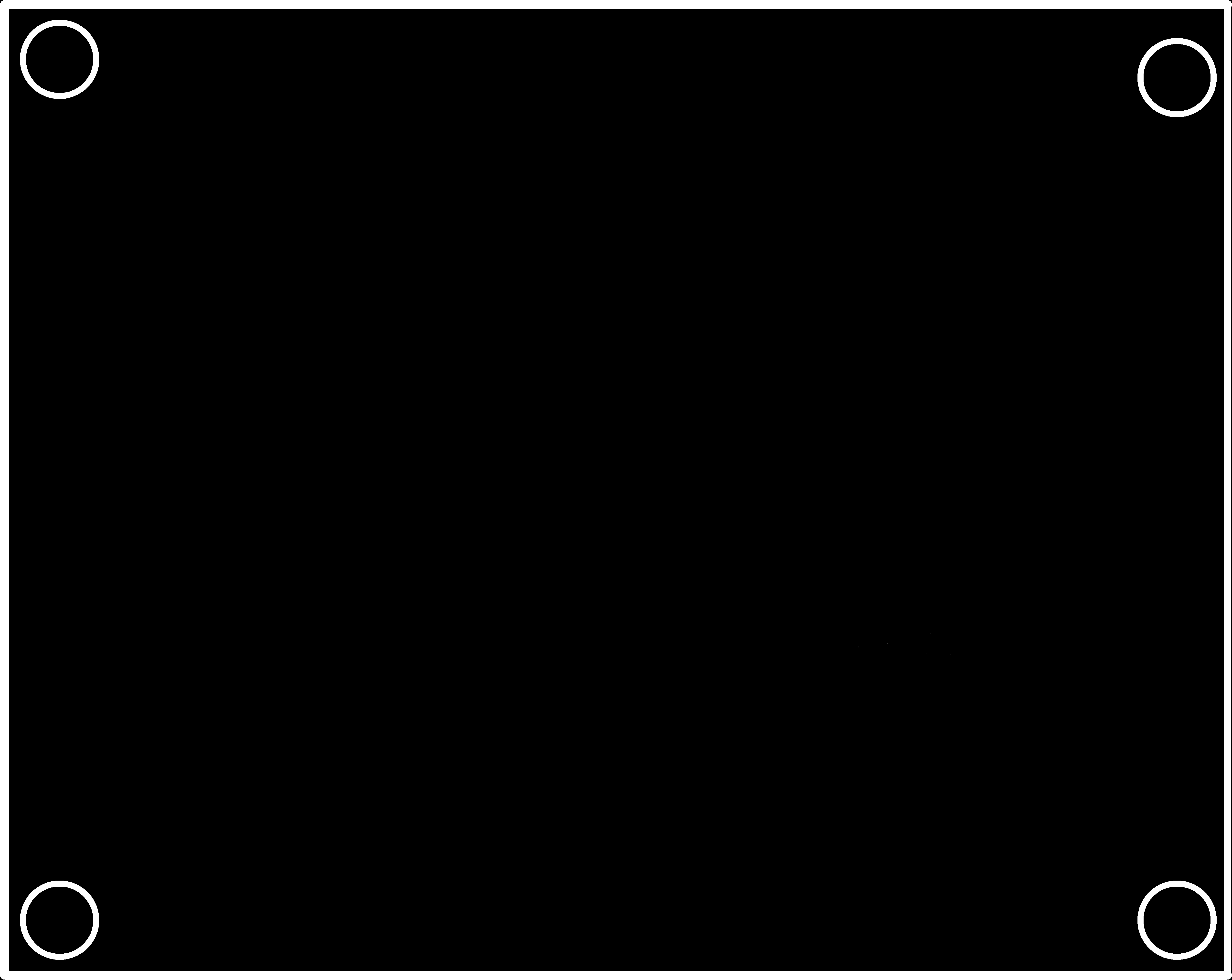
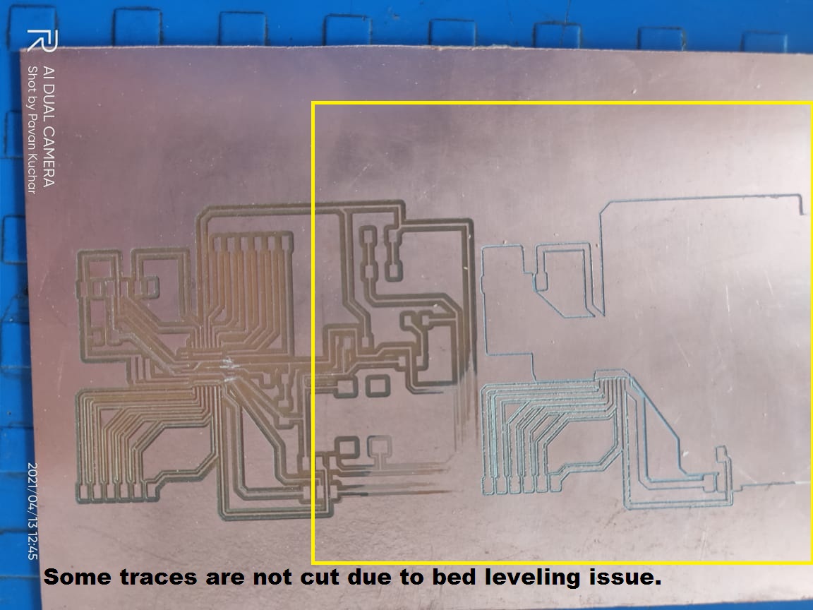
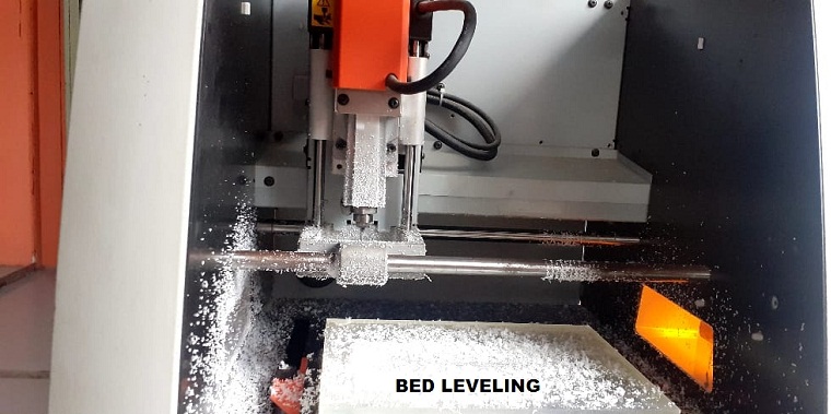
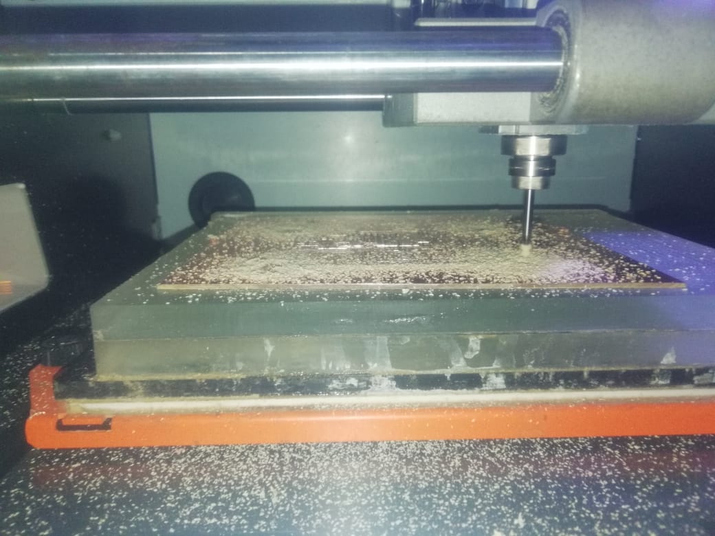
After Completing this, I have to go for milling this board so before that i had saved this trace and cutout of board in .PNG format and given to the milling
Due to some technical issue with SRM Machine (Bed leveling problem) We all are not able to mill our microcontroller board in this week. So for this bed leveling issue we had remove the sacrificial and applied the acrylic sheet. Still, we had the levelling issue. Then we milled the acrylic sheet applied as sacrificial layer using the 1/8 mill bit for making it even and levelling.
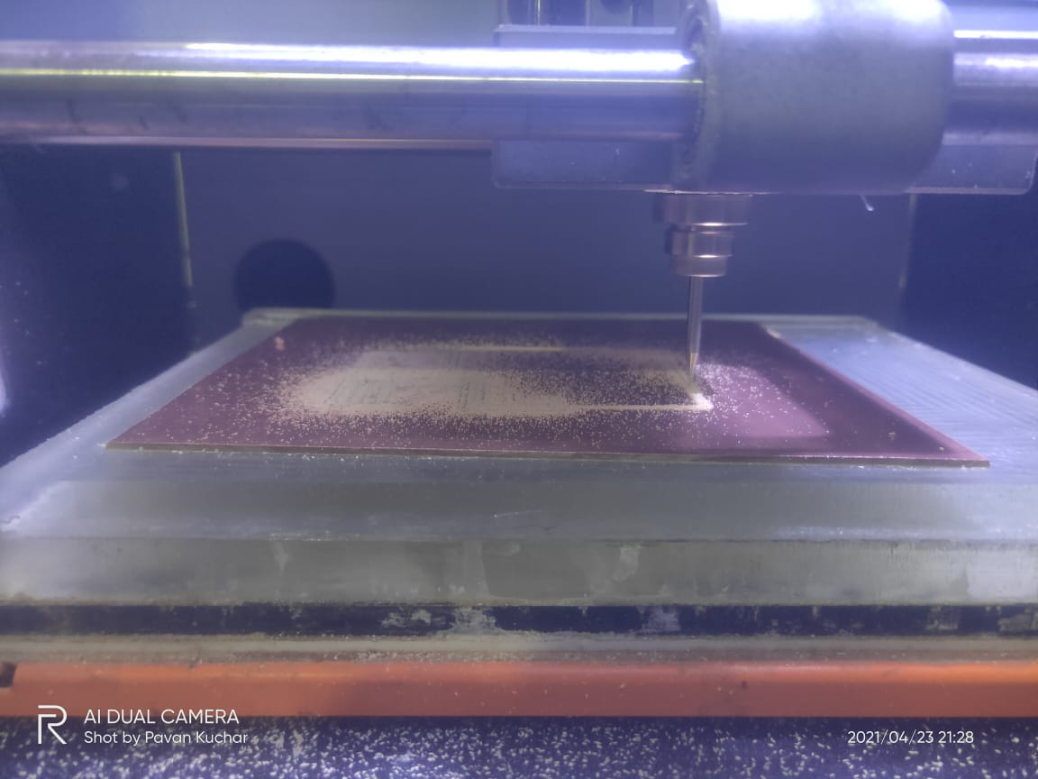
After Sorting this issue we have Proceed for next task i.e Milling and soldering the board.
Milling and Soldering of ATMEGA328P
For milling of this Microcontroller board I had used SRM-20 Milling machine and fab Mods used for communication purpose. So lets begin the milling of ATMEGA328P Board.
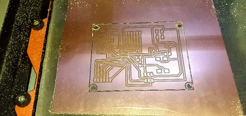
Here, my board is ready now.
Next part is to solder the required component with this board.
List of required components is as below.
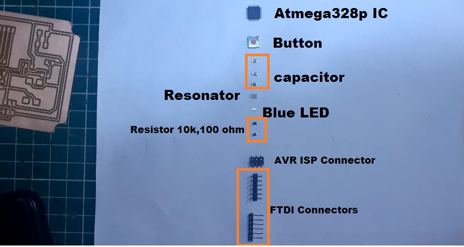
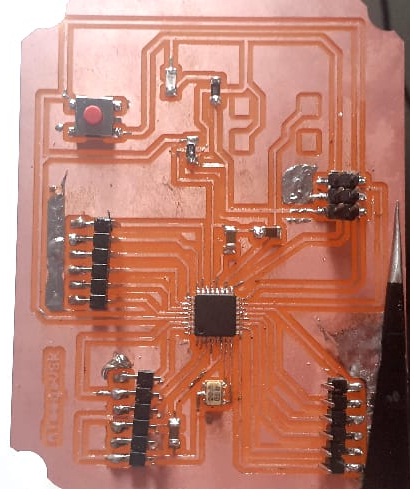
Hero Shot of my ATMEGA328P Board.
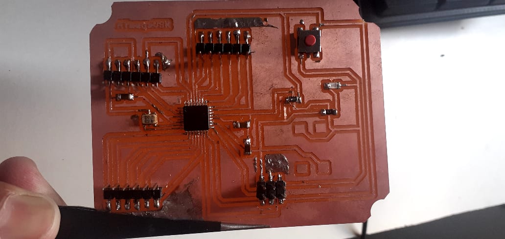
Here one issue happened with my board while milling, The whole i have routed was not milled, because of small distance in between cutting trace and side wholes.
ATMEGA328P Microcontroller Board.
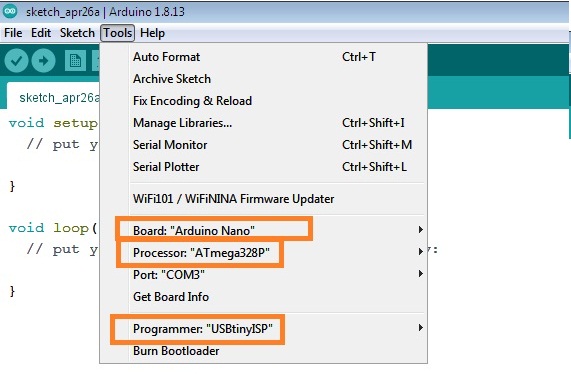
Now, my Atmega328P Microcontroller Board is ready now, I had to check whether is workign properly or not before that i need to upload the program to ATMega328p board using programmed USBtinyISP which we have designed in electronics Production week.
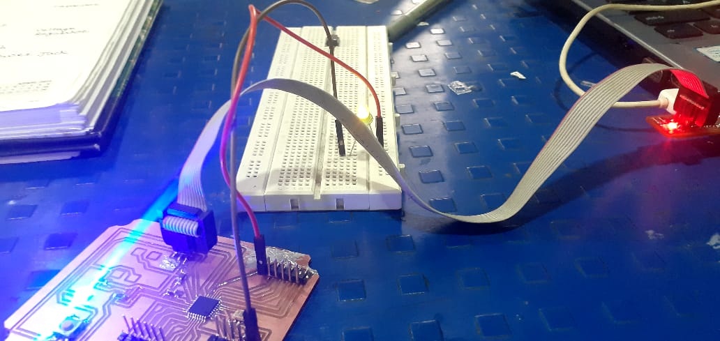
So, i have done this by uploading the blink led code with Atmega 328p Board.
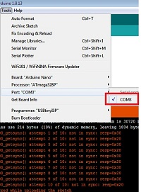
First, I have open the Arduino IDE and select this.
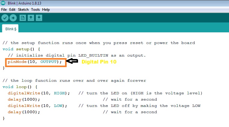
Then i have connect led to digital pin number 10
Here, I have faced one problem the led was blinking but it will take 15 second to on and off while delay was only 1 sec.
So In this case as prof. Neil suggested in electronics production week we need to burn butloader while programming any board. so from arduino IDE I have done this.
So,after that it was working properly as per programmed.
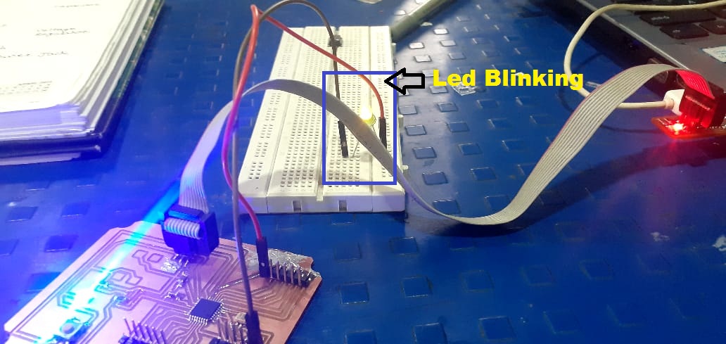
After that I have checked all input and output pin's whether getting the ouput on all pins or not by blinking LED on respective pin.
Interfacing of Input Devices as a temperature sensor on my Designed Atmega328p Board.
After testing of Prepared board Atmega328p, next I had to test the temperature sensors like DHT11,DS18B20,pt1000 on it
Testing of DHT11 Temperature Sensor with ATMEGA328P Board.
First of all, I have checked the DHT11 Sensor to Atmega328p microcontroller Board.
But here I have faced one problmes when I upload the code in Atmega328p board then in arduino IDE, I had to see the values of temperature on serial monitor. But there was no any COM port detected because as a programmer i am using USBtiny So there no any serial communcation devices availble. I got here the error the COM port not detected.
So, I talk this issue with my friend Mohit He suggest me you sholud used FTDI for series communication.
Because for serial communication we need the serial communation protocol here
So, here I dont have my own FTDI serial Communication device, then i decided to mill and prepare this device download the designed file from Fabacademy websites.
Now, for testing the sensors, I have used Arduino Uno for only the Serial communication.
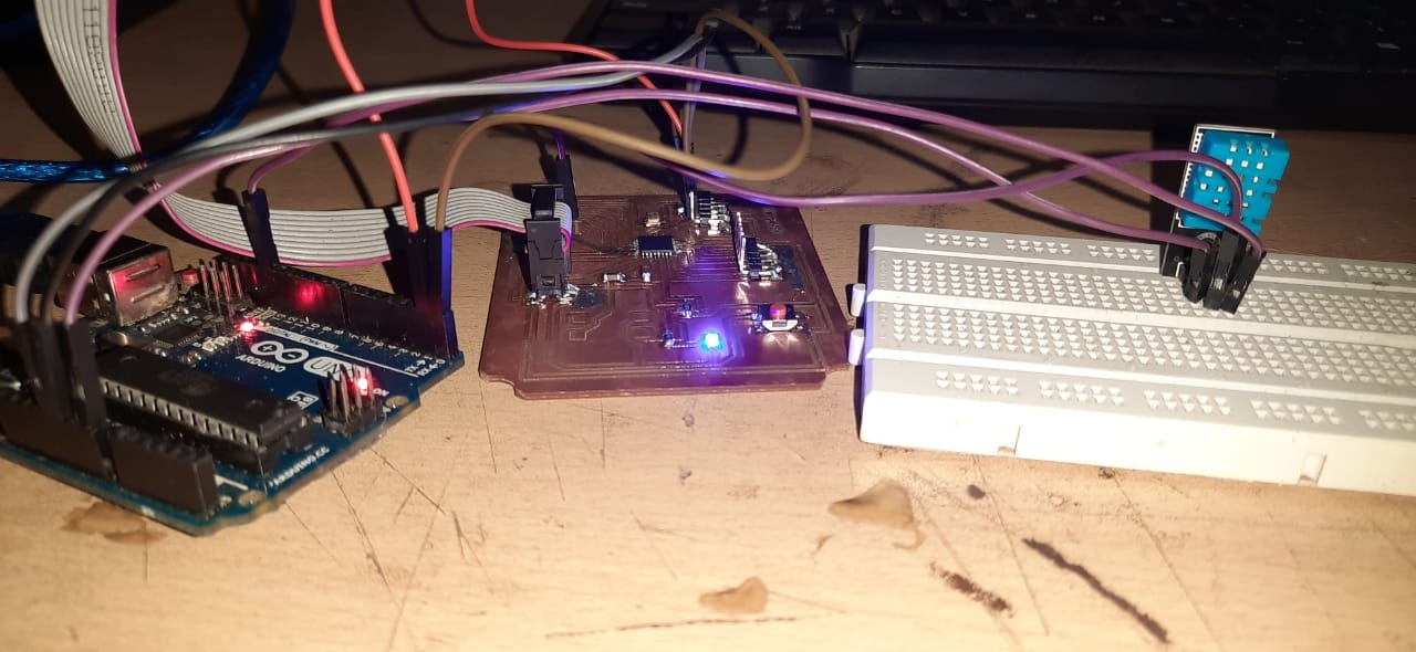
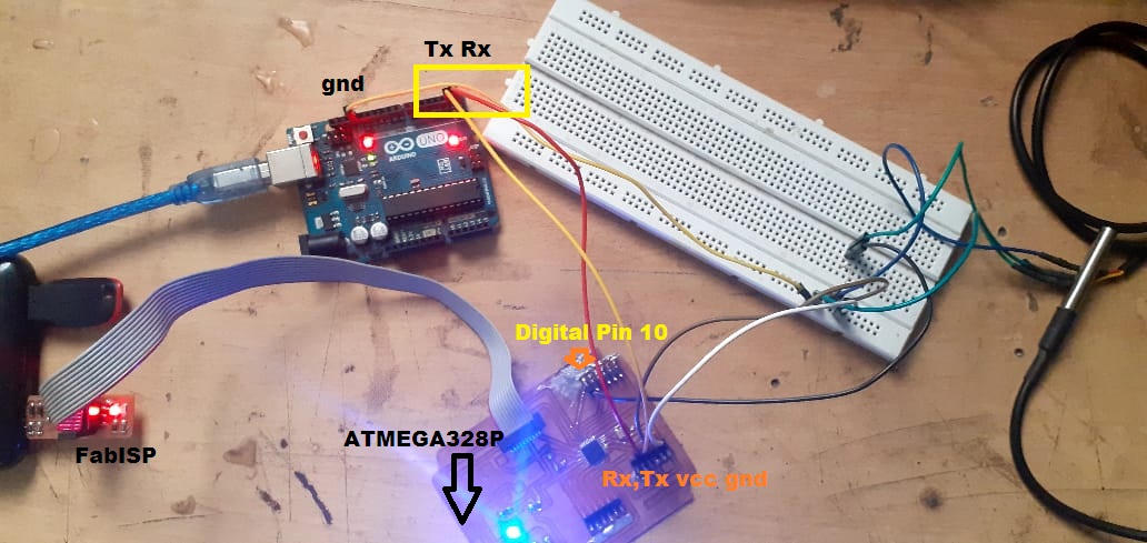
Here, you can see I had to used arduino Uno Board ,Becuase i wanted to see the data taken by DHT 11 sensor on serial monitor of arduino.So microcontroller transmit this input data on serial monitor of Arduino IDE serially.So Atmega 328p will transmit this data to PC and PC will receive it serially. So i used Tx and Rx pins of Arduino for this serial communication between atmega 328p microcontroller and PC s(Serial monitor).
After that I have upload the program of DHT11 Sensor
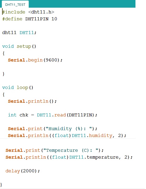
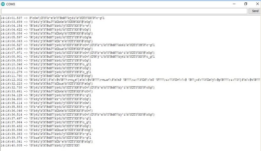
Now, Again I have faced one problem, when I have uploaded the above program and open the serial monitor window, Not getting the proper reading, there was showing some garbage Values.This is becasue of resonator which i have used in my board having 20Mhz Frequency due to this issue serial monitor cant read the data properly.
This kind of garbage values appear on screen
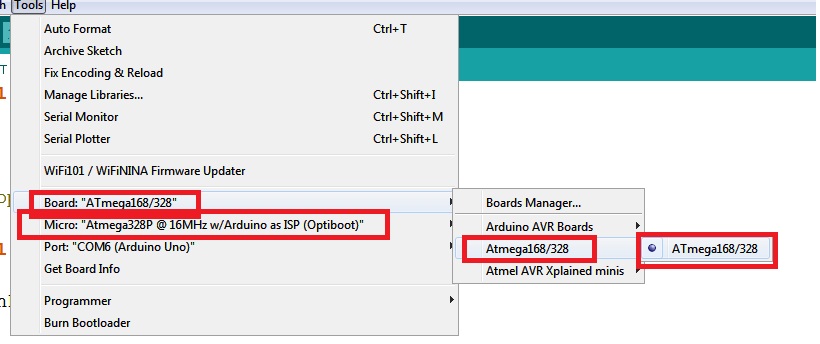
To solve this issue, I need to 8Mhz Board for proper communication.
Installing Board of ATMEGA328P
Open the Arduino IDE preferences window and add the following URL to the Additional Boards Manager URLs list:
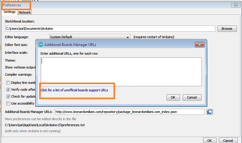
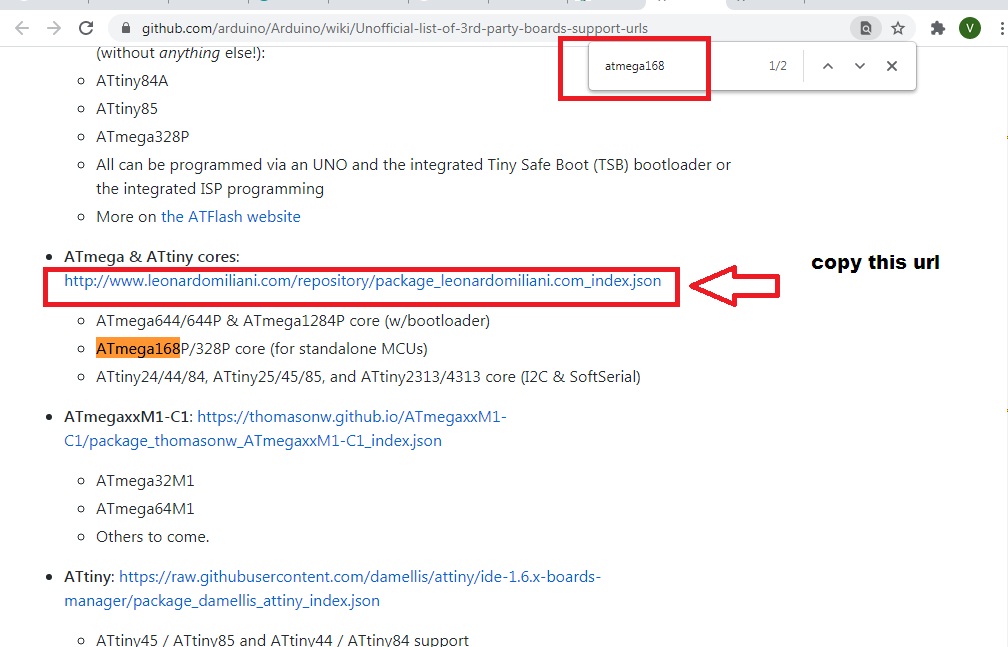
Then Copy this url and insert it into the preferences,and then go to board manager and find this board and click on installed, now board is in your list.
Here is the referance LINK of Board
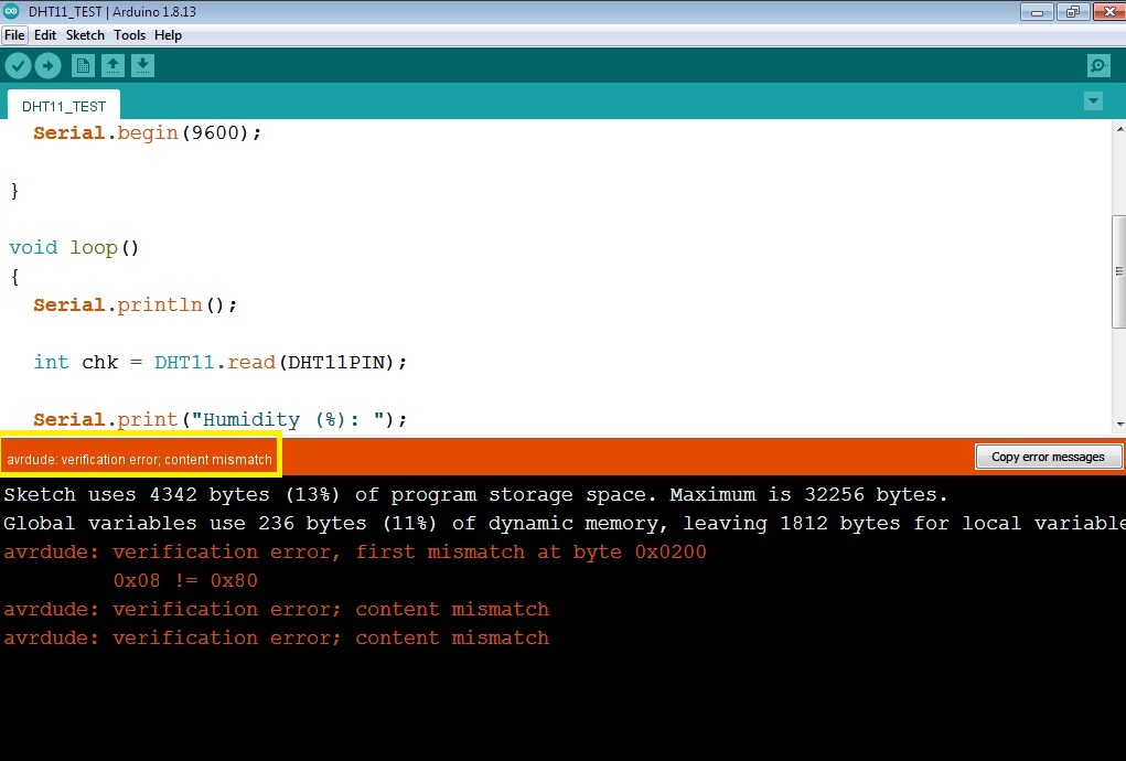
Here I am again facing the problem with windows 7 32 bit operating system. when I tried to upload this program from my own laptop its gives the error "avrdude: verification error; content mismatch" and I didnt found the solution, so i tried to upload from windows 10 operating system.
This error Only when I have used USBtiny as programmer.
Then I have again upload the same program on windows 10 system , now serial monitor of arduino IDE showing the proper reading of temperature as well as humidity.
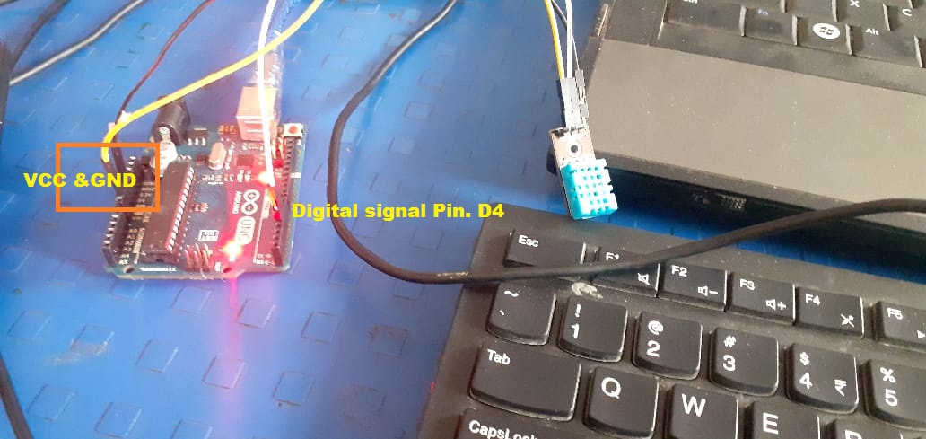
This is the circuit that I have make the connections.

This was the results sense by DHT11 temperature sensors at room temperature.
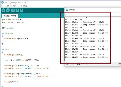
Here, Even I have changed the Baud rate from 9600 to 115200 serial monitor read the proper reading of temperature.
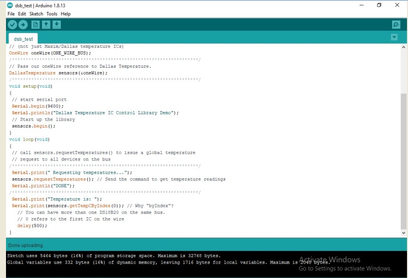
Then I have test the ds18b20 sensor on my ATMEGA328P Board.
This when I have upload the program.
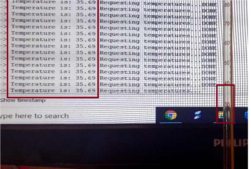
Here, I have checked the displyed reading of serial monitor with Thermameter.There was showing near about 35 Degree celcius on Thermameter.
The reading shows by thermameter was aprox. match with temprature sensor.
Then, I have checked the NTC thermister on my ATMEGA328P board. First made the connection as per circuit diagram.
Here, Program with serial Monitor gives the correct reading.
After that, I have tried to cheked the PT1000 temperature sensor, as this sensor I am going to use in my final project detail about this sensor, I have already explained.
Here, I have test this sensor on my designed ATMEGA328P Board.
The below Image shows the uploaded program on Arduino IDE with reading are displayed on serial Monitor Window.
You can see here getting two values on serial monitor of Arduino IDE, becuase when temperature changed the value of resitance also change that respect voltage across the resitance also change. For accurate and precise reading I need to calibrate this sensors.
This is the video of my borad tesing with Pt1000 Temprature sensor.
Learning Outcomes:-
1. From this week of assignment I understood the role of input devices in electronics system.
2. I have learnt the different types of temperature sensor and its various applications.
3. I have understood how to connect different kind of sensor temperature to Arduino uno Microcontroller Board.
4.. I have understood the desinging of Atmega328p Microcontroller board in Eagle software and the its routing.
5. I have understood the how to connect the different kind of temperature sensor with my designed ATMEGA328P Microcontroller Board.
6. I have understood the how we can communicate serially with PC to Microcontroller board using serial cmmunication protocol.
DOWNLOAD's
Download my original file here