Task to be Perform for this week
1) Group Assignment
- design a machine that includes mechanism+actuation+automation.
- build the mechanical parts and operate it manually.
- document the group project and your individual contribution.
For more details about this assignment click here. GROUP ASSIGNMENT
2)Individual Assignment :
Document your individual contribution.
Learning outcomes
1) Work and communicate effectively in a team and independently
2) Design, plan and build a system
3) Analyse and solve technical problems
4) Recognise opportunities for improvements in the design
Checklist
1. Documented the machine building process to the group page
2. Documented your individual contribution to this project on your own website
3. Linked to the group page from your individual page as well as from group page to your individual pages
4. Shown how your team planned and executed the project (Group page)
5. Described problems and how the team solved them (Group page)
6. Listed future development opportunities for this project (Group page)
7. Included your design files (Group page)
8. Optionally included an aprox. 1 min video (1920x1080 HTML5 MP4) + slide (1920x1080 PNG) (Group page)
Introduction to Make a machine
The task for the week is to develope the mchines that include mechanism, actuation and automation. The Machine design is the creation of new and better machines and improving the existing ones. The process of design is a long and time consuming one. From the study of existing ideas, a new idea has to be conceived. We have refer lot of existing machine develope in Fab Lab. But for new idea, we have to keeping in mind, its commercial success and given shapes and form in the form of drawing. In the preparation of drawing care must be taken of the availability of funds, time and material.
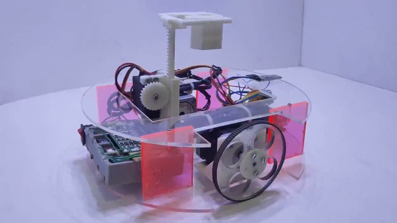
considering above factors we have taken the brainstorming session with our FabLAB instructor at Vigyan Ashram, and explore the various ideas about make a machine with fablab members, and Finally decided to make a machine called "चित्रcar" i.e. Plotter Machine. which can plot or draw any image of any scale>
After that we decided the flow of machine week which include all the working process this below image shows the flowchart which i have Drawn in draw.io software Link
This flow chart shows how we are going too proceed this work of machine design week.it shows the overall planing and the final sketch of the machine.
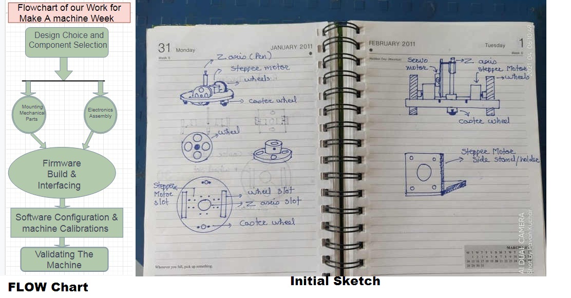
Once we decide the Final skecth and overall planning about the machine week we started our work.
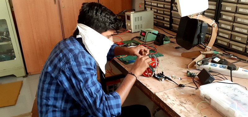
First we have done the trial test on DIY kit available in our Fablab
First of all for trial purpose we decided to take the all material required for making any kind of machine or robot.
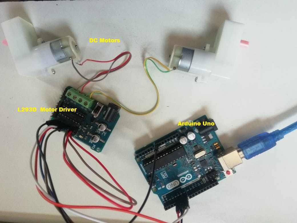
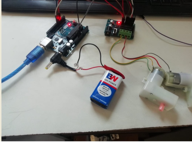
We have taken the two DC motor , Chesis, Arduino uni Microcontroller Board , Driver IC's L293D and all required component to test the machine.
- 1. DC motors
2. L293d Driver
3. Chessis
4. Arduino Uno
5. 9 V Battery
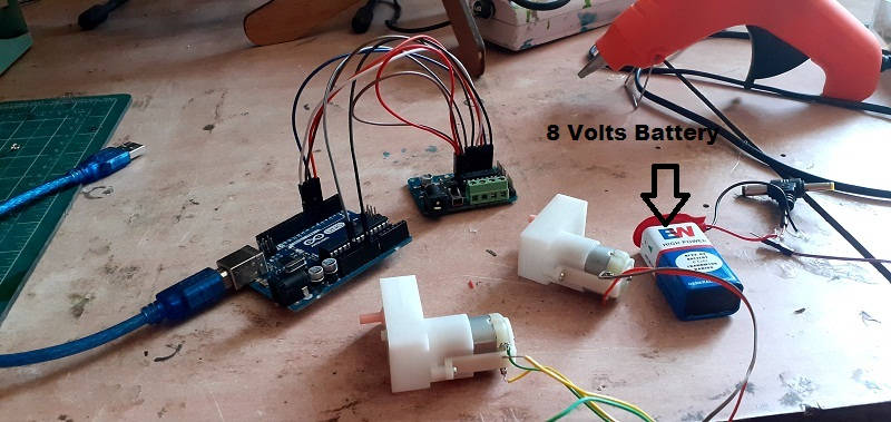
Then We have powerup the circuit by connecting 9volts battery as source.
About DC Motor Testing With L293D driver
Need for Motor Driver Circuits/ICs
We Can run the any DC motor by directly giving the supply but we can't controlled it precisely,in that case we required drivers because,
In motor interfacing with controllers, primary requirement for the operation of the controller is low voltage and small amount of current. But the motors require a high voltage and current for its operation. In other words we can say the output of the controller or processor is not enough to drive a motor. In such a case direct interfacing of controllers to the motor is not possible. So we use a Motor Driver Circuit or Motor Driver IC.
Not only in the case of controllers, while connecting motors with 555 timer ICs or 74 series ICs; they also cannot provide the large current required by the motor. If direct connection is given, there might be a chance of damage to the IC.
Types of DC Motor Driver Circuits
There are various types of motor drivers circuit availble in market as per the need of torque and speed which we can control using the different driver circuit
1. Transistor Based DC Motor Driver Circuit.
2. H Bridge Circuit.
3. Using L293D
so, I have make the connection of DC motor with Drivers by refferring the various tutorials.
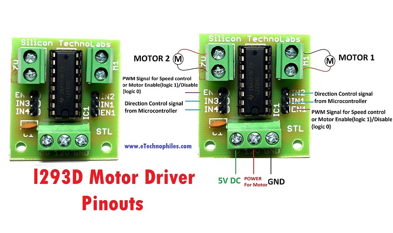
About L293D Driver Circuit
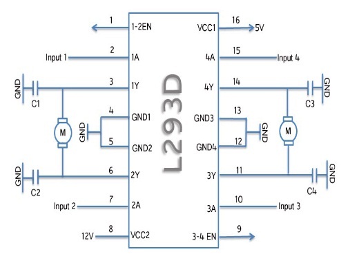
L293D is a dual H bridge motor driver IC. This 16 pin motor driver IC can drive the motors in anti-clockwise and clockwise direction. The connection of the DC motors to L293D IC is given below.
Pin Description of L293D
-1 and 9 are Enable Pins.
-2, 7, 10, 15 are Input pins.
-3,6,11,14 are output pins.
-4, 5, 12, 13 are the Ground pins.
- 8 and 16 pins are for Vcc.
First, I have reffered the pin diagram of L293D IC's and also the configurations of this driver with microcontroller board
By reffering the pin out i have made the connection as per requirement and test the motor by interfacing with arduino uno using ARDUINO IDE
Connections Diagram
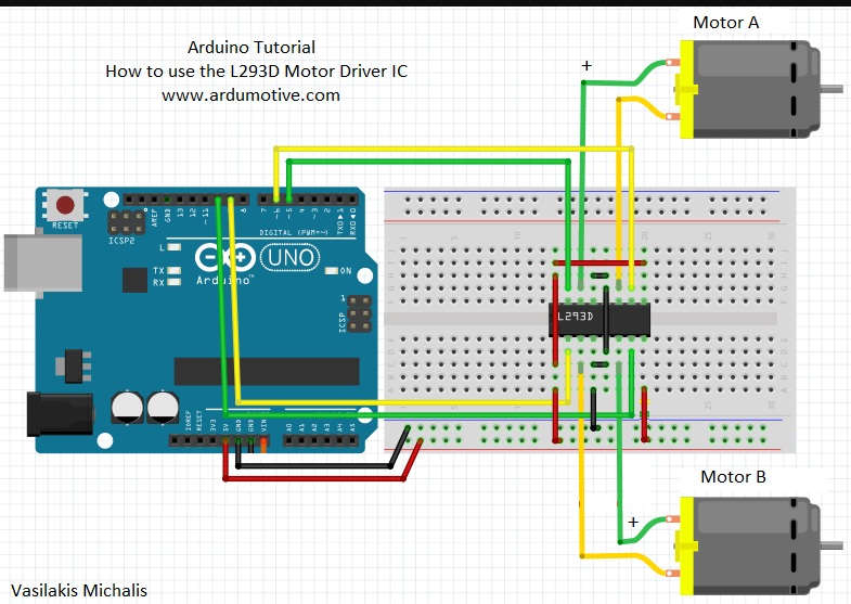
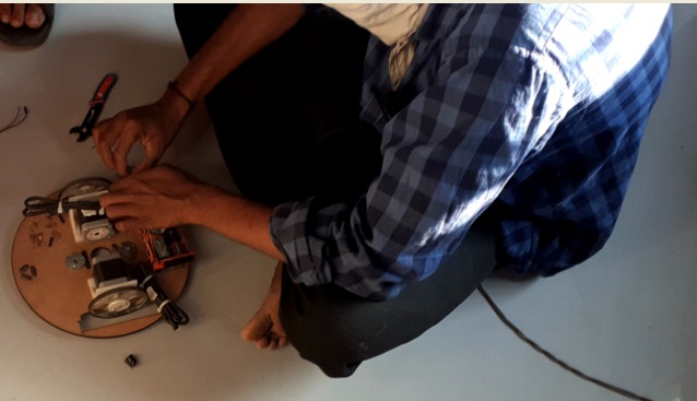
In this way I have make the connections and Mount all the components and wheels on chessis
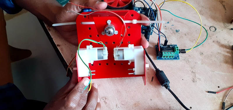
After that for Trial purpose we have run the test code for this module to run the DC motors
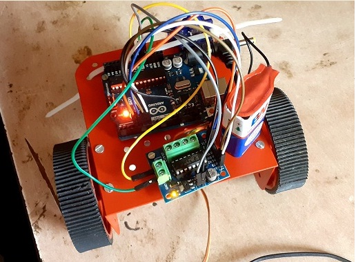
Here , 9 Volts Power is given to machine through battery but it is obsevered that, machine is not working propely may be because of low voltage. So, in this case we required to change the souce, now we have connected 12 volts supply through adaptor and run the same test code, it is working properly
Final Assembly of DIY kit with Dc motors and 8 volts battery Power Source.
Video to test the Diy kit with DC motors Assembly
Once Trail on DIY kit is completed successfully we will go on main task , to design the X-Y axis , Lesser Cutting, 3D printing , Eletronics trobleshooting, Designing of z- axis and Software Interfacing.
So,we divide the task to each group member and as per our willingness
First we decided the our machine should be RF base ,So I have worked on interfacing of Nrf24 module with microcontroller
1. What is NRF24L01 module
NRF24L01 is a wireless transceiver module (works on SPI Protocol), which is used for sending and receiving data at an operating radio frequency of 2.4 to 2.5 GHz ISM band. for more detail i have reffered this link
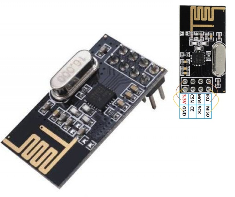
2. How to interface it with Microcontroller Board. for Transmitter
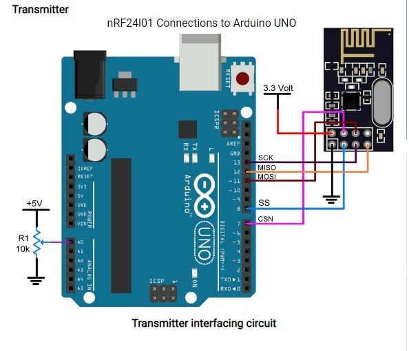
For Receiver we had to make a same connections
3.How It works
Having two or more Arduino boards be able to communicate with each other wirelessly over a distance opens lots of possibilities like remotely monitoring sensor data, controlling robots, home automation and the list goes on. And when it comes down to having inexpensive yet reliable 2-way RF solutions, no one does a better job than nRF24L01+ transceiver module.
nRF24L01+ (plus) transceiver module can often be obtained online for less than two dollars, making it one of the most inexpensive data communication options that you can get. And best of all, these modules are super tiny, allowing you to incorporate a wireless interface into almost any project. for more detail I have reffered this link
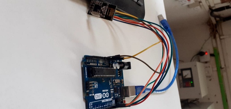
Once connection is done then i need to connect the arduino uno with my PC
This is for transmmit the data
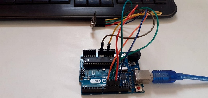
This is to Receive the data
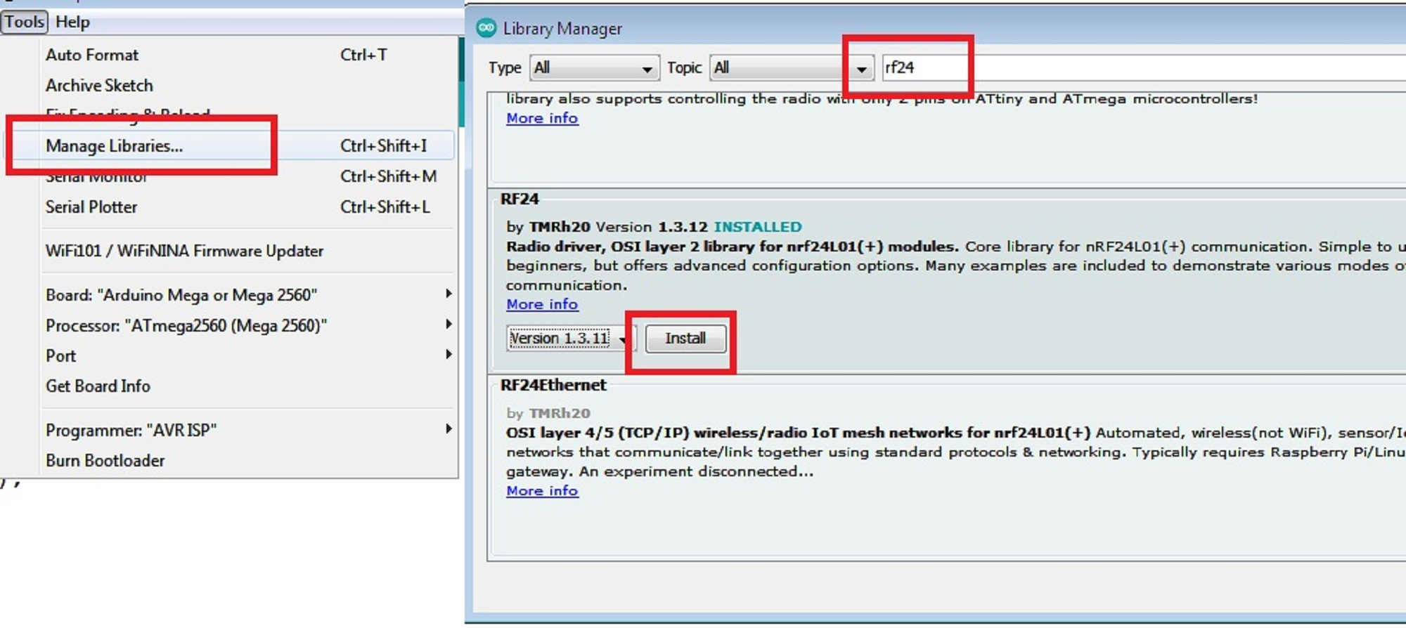
But now i need to installed the library files in the Arduino IDE, So, I have installed it first otherwise it gives the error.
For This nrf24 Module i need to update from library manager
Once Connections and libraries are installed succesfully, we need to go for testing this module
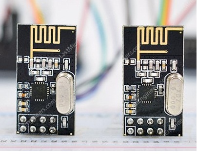
For testing we required to set one is for transmmiter and another is receiver.
So, Me and Mohit tested this module by exicuting the test codes( Both transmmiter and Receiver ) given in example of Arduino IDE.
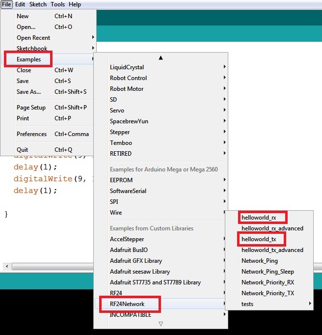
We have open this two codes and run it on different Laptop it was tested succesfully
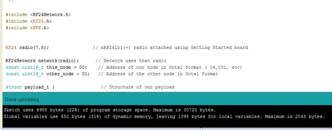
This is the code for transmit and Receiver
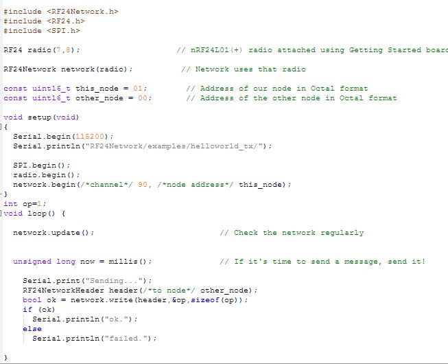
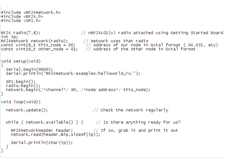
Then we have upload this code in the arduino IDE for communicating the data.
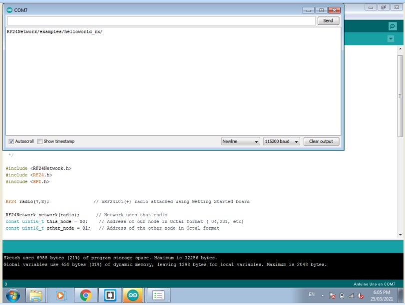
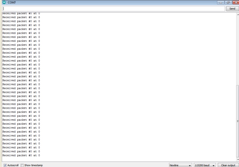
Initially we don't get any signal at receiver side.
Here we got some data from receiver side when we reset the arduino Board by pressing the reset button .
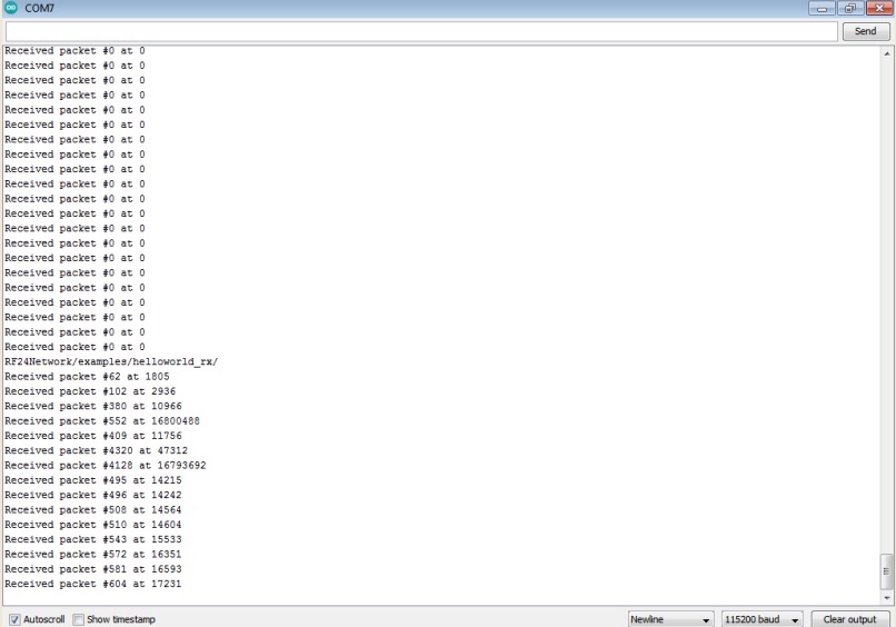
So, from this we can say that the nrf24 module is giving some data.
This is all about testing of Nrf24 Modules for Transmmit as well as Receive the data.
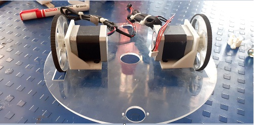
After that we have started working on designing the Required mechanical Part of machine,Lesser Cutting and 3D printing.
As said we have already divide the task in five member as per task we have worked the details about the assembling and design the various parts of the machine mentioned in group page.
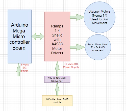
Electronics Component to be used in the machine
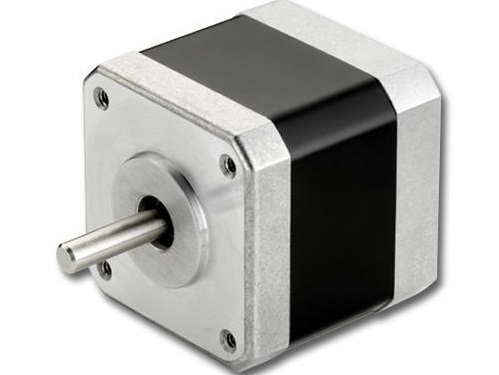
1. Nema 17 Stepper Motor (For X-Y axis Movement )
2. Stepper Motor Drivers.
3. Arduino mega with RAMPS 1.4 Sheild.
4. Bluetooth Module.
5. 16 Volts BMS Module.
6. DC to DC Buck Converter ( Output 12v DC).
7. Survo Motor Used for Z- AXIS movement
As Decided, My task is to test all the above component is working properly or not and power requirement for the machine , so i have tested these one by one
1.Testing of Stepper Motor
For machine we have used Nema 17 4.2 Kg-cm Bipolar Stepper Motor which is generally used in Robotics and 3D printers.
For that first i have read the data sheet of this motor and find the voltage and current required for this configurations of motors LINK
Then, First i have used Easy driver Modules for testing the stepper motor which i need to move X-Y axis as per given Command
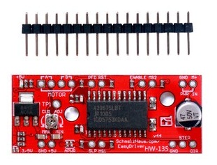
To run a stpper motor i also used motor driver which provide greater flexibility and control over your stepper motor .I am using EASY DRIVER which is compatible with most microcntroller(Arduino Uno) that can output a digital 0V to 5V .This module require a 7V to 30V power supply for a motor. EasyDriver drives bi-polar motors and motors wired as bi-polar. i.e. 4, 6 or 8 wire stepper motors. The microstep select (MS1 and MS2) pins of the A3967 are broken out allowing adjustments to the micro-stepping resolution. The sleep and enable pins are also broken out for further control.
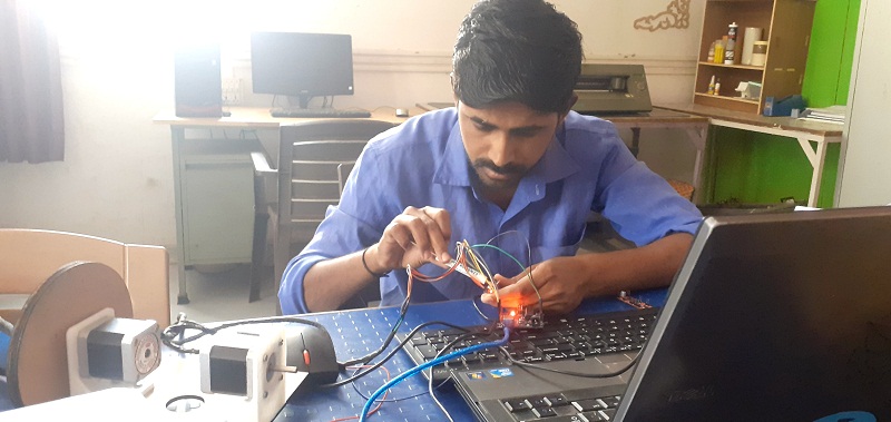
After that i have run the test code through arduino IDE, the motors are running as per given code but it was taking vibrations may be because of low power getting low torque
But Here it is obsevered that when i connect 12 volt Power supply through DC regulated power supply Easydrivers module was heat up more, even while testing this drivers, two drivers are damage.
The Video shows droped in voltage in Easydriver when 12Volts Dc given.Droped in voltage near about 10 volts this is becasue of any short circuit.
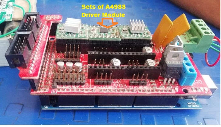
Then i disscussed with instructor and Mohit they suggested to use another driver i.e A4988 Driver Module with sheild on Arduino mega Microcontroller Board
Pin Diagram of A4988 Stepper Motor Driver.
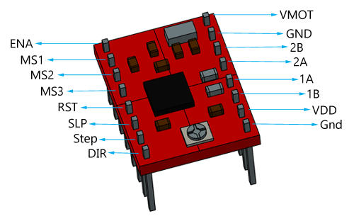
For testing of stepper motor on this driver I have reffered the tutorial and data sheet of this A4988 Driver Module. link
After that i have connect the circuit as per below image
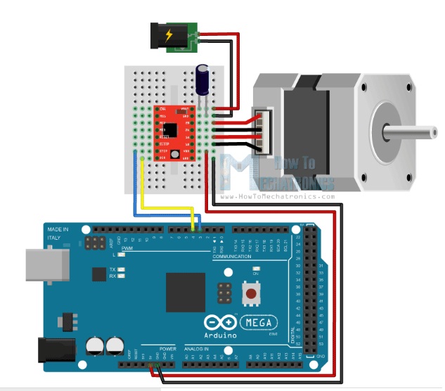
After i have follwed the step for motor control and microstepping as per given in tutorial for smoothely Control of stepper motor
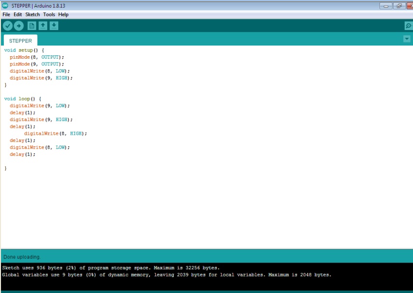
Then, Run this test code to run the stepper motor
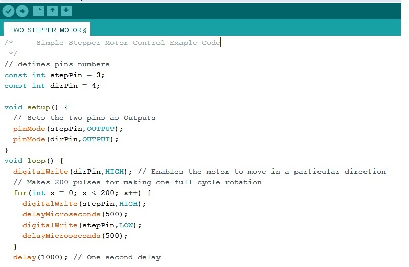
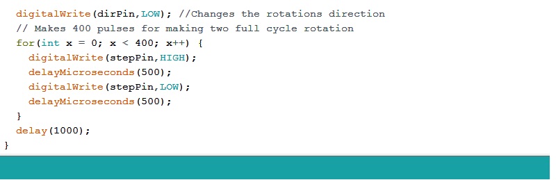
it is observed that motors are runnig smothely as per given code
Once the testing has done we have used Arduino mega with drivers mounted RAMPS 1.4 sheild, Most of the time this module used in 3D printers
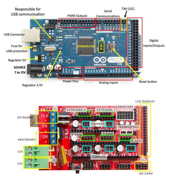
After struggling with Easy driver we have used Arduino mega board with Ramps 1.4 sheild drivers mounted with stepper motor driver module A4988.
Arduino MEGA Shield – RAMPS
The RAMPS 1.4 3D Printer controller+Mega2560 with cable compatible with Arduino +5Pcs A4988 Driver with heat sink Kit is the new Robu.in 3D Printer Kit, developed specially for those who are interested in the 3D printer. The RAMPS 1.4 is Mega Pololu Shield, or RAMPS for, design to fit the entire electronics needed for a RepRap in one small package for low cost. RAMPS interfaces a Mega with the powerful MEGA Arduino platform and has plenty room for expansion. The modular design includes the plug in stepper drivers and extruder control electronics on MEGA Arduino shield for easy service, part replacement, upgrade-ability, and expansion. Additionally, a number of Arduino expansion boards can be added to the system. As long as the main RAMPS board is kept to the top of the stack.
For this i have used the pin configurations and connections of Ramps 1.4 Module with arduino mega input/output pins To know this pin configuration i have reffered this site LINK
After that , i have worked on Powering this modules,
This Ramps sheild and our machine required 12 volts DC power so one of the our group member Mr. Rahul having 16 Volts BMS with lithium ion batteries
This battery Module having for batteries are connected in series each having the output voltage is 4.2 volts.and it will take load approximately upto 4 Amp.
As batteries connected in series, total output we get across the module appox. is 16 Volts.
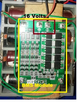
Here, we get 16 Volts output Voltage
Now, as i said we have used two nema 17 stepper motor of 4.2 kg-cm torque as per data sheet when this motor on full load conditions it will take appox. 1.7 Amp current but we have tested our machine on trial and error basis and used microstepping concept for smoothness.
We can set the current by using potentiometer present on driver.
From this BMS module we required 12volts DC supply for that i have used LM2596S DC-DC Buck Converter Power Supply.
By varying this potentiometer we can adjust the output as required
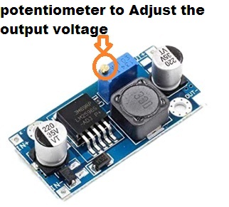
Then i have made the connection of this buck converter with battery module and adjust the output 12 volts
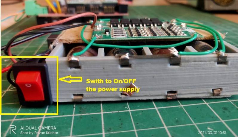
After that i have made one connector for the powering the ramp1.4 sheild by using sodering Gun because we need the proper connetcor so that we can power the shield.
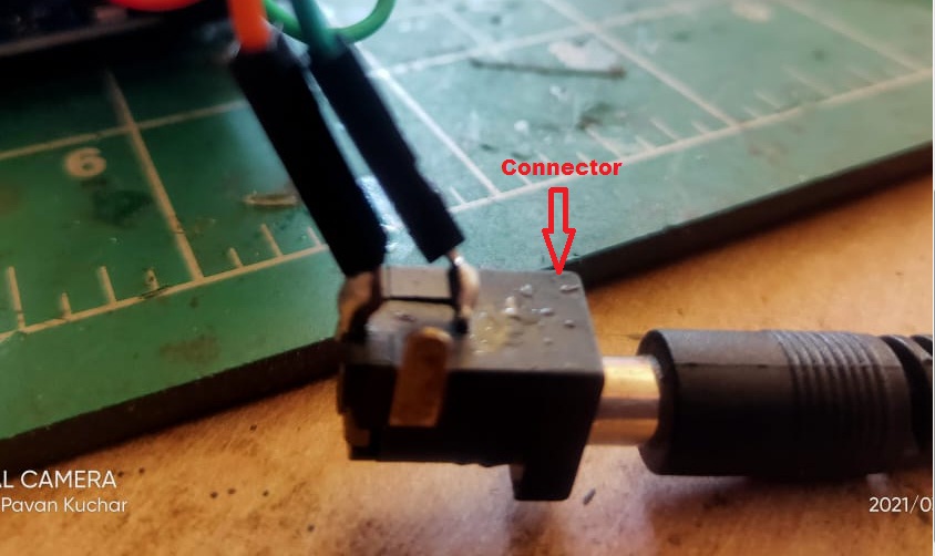
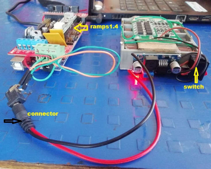
This is how I have made the power source for machine.
Now, I need to go for how we can connect the stepper motor with the Arduino mega with ramps sheild.
For Connections of Arduino mega with its shield circuit we have reffered this SCHEMATIC
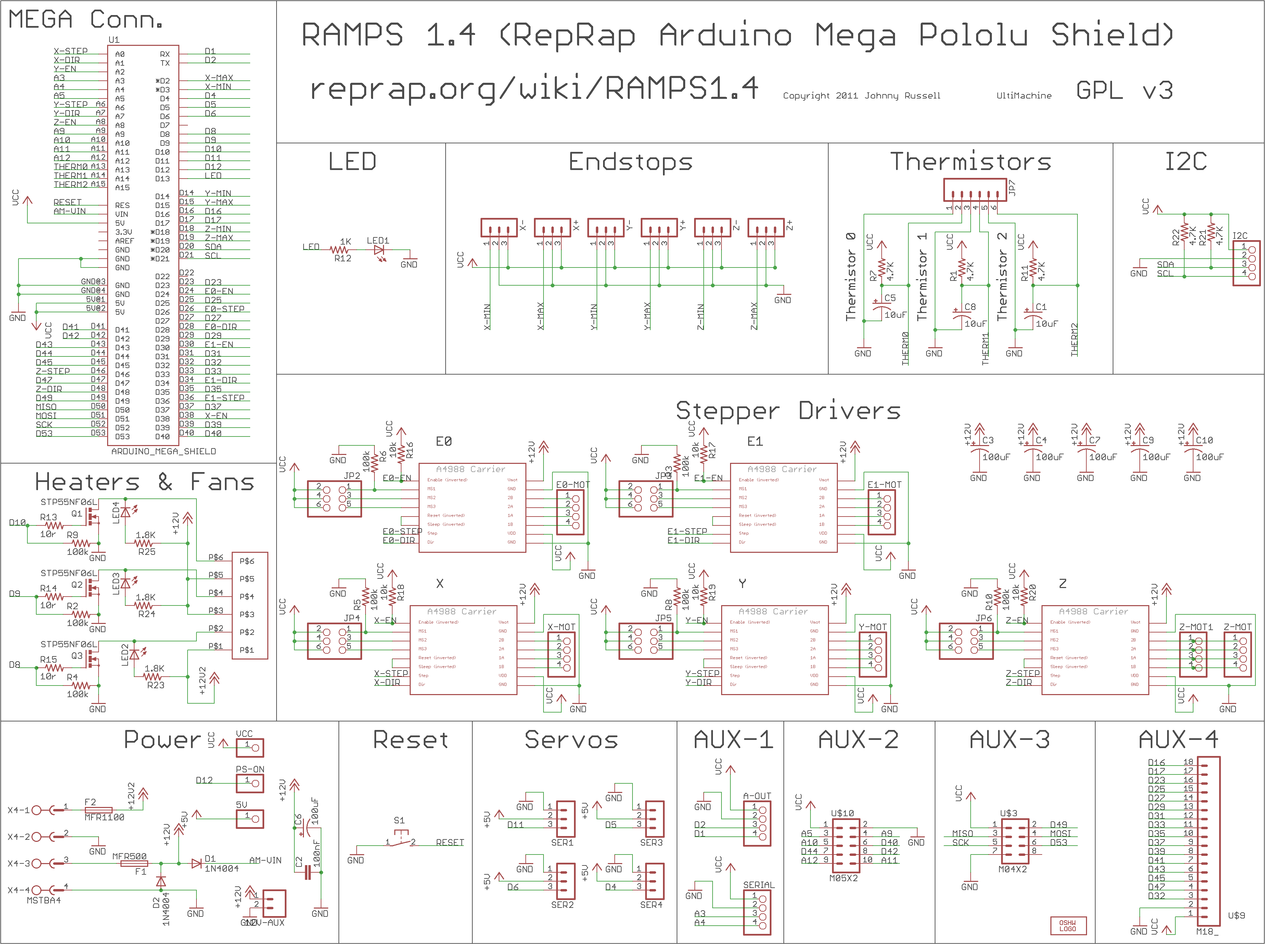
By reffering the Schematic we have connect our circuit and the motor to Arduino mega .
After this the machine we have made the body of acrylic Material.
Then I have drawn the block diagram for this is how overall connection of the electronics part
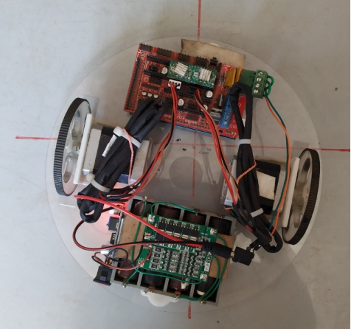
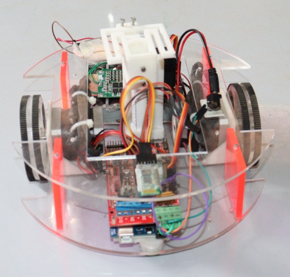
Then properly placing of Microcontroller Board and BMS Module on the body of machine
Final block diagram is as follow.
After that I have soldered some required Component on the machine.
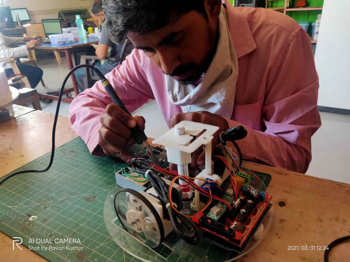
Our final machine is ready now.
After the lots of troubleshooting we have finally got the results and our machine Chitrakar is ready which can able to draw the design of any dimenssions .
The Overall Detail about the Machine is on Group PageClick Here
Problems I have faced
While testing the stepper motor with easy driver module the driver module heatup so much
DOWNLOAD's
Download my original file here