Task to be Perform for this week
2) Individual Assignment:
Read a microcontroller data sheet
program your board to do something,with as many different programming languages and programming environments as possible
1) Group Assignment :
Compare the performance and development workflows
for other architectures
Learning outcomes
1) Identify relevant information in a microcontroller datasheet.
2) Implement programming protocols
Introduction to Embedded System
An embedded system can be thought of as a computer hardware system having software
embedded in it. An embedded system can be an independent system or it can be a part of a large
system. An embedded system is a microcontroller or microprocessor based system which is
designed to perform a specific task. For example, a fire alarm is an embedded system; it will sense only smoke
An embedded system has three components −
It has hardware.
It has application software.
It has Real Time Operating system (RTOS) that supervises the application software and
provide mechanism to let the processor run a process as per scheduling by following a
plan to control the latencies. RTOS defines the way the system works. It sets the rules
during the execution of application program. A small scale embedded system may not
have RTOS.
So we can define an embedded system as a Microcontroller based, software driven, reliable,
real-time control system.
Basic Structure of an Embedded System
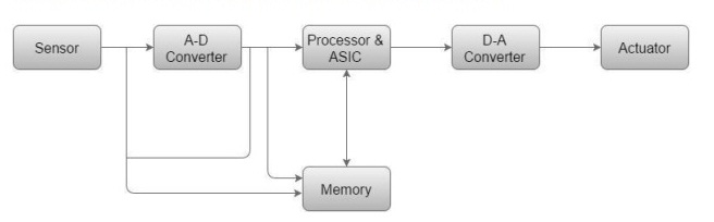
Sensor − It measures the physical quantity and converts it to an electrical signal which
can be read by an observer or by any electronic instrument like an A2D converter. A sensor stores the measured quantity to the memory.
A-D Converter − An analog-to-digital converter converts the analog signal sent by the
sensor into a digital signal.
Processor & ASICs − Processors process the data to measure the output and store it to
the memory.
D-A Converter − A digital-to-analog converter converts the digital data fed by the
processor to analog data
Actuator − An actuator compares the output given by the D-A Converter to the actual
(expected) output stored in it and stores the approved output.
Source
Embedded Software or Program allow Hardware to monitor external events (Inputs) and control external devices (Outputs) accordingly. During this process, the program for an Embedded System may have to directly manipulate the internal architecture of the Embedded Hardware (usually the processor) such as Timers, Serial Communications Interface, Interrupt Handling, and I/O Ports etc. There are many programming languages that are used for Embedded Systems. In the process of making a better embedded system, the programming of the system plays a vital role and hence, the selection of the Programming Language is very important. In this assignment, we trying to develop the code using different languages and environments.
About Group Assignment:-
The task for the week is to compare the performance and development workflows for other architecture. Here We have worked on Microbit, ATMEGA 328P(Ardunio), and Rasberry Pi.
In group assignment i have individually worked on Microbit and Risberry Pi Controller
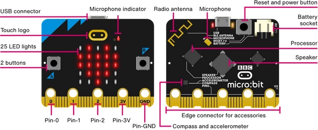
About Microbit
>The BBC micro:bit is a pocket-sized computer that introduces you to how software and hardware work together. It has an LED light display, buttons, sensors and many input/output features that, when programmed, let it interact with you and your world.
The new micro:bit with sound adds a built-in microphone and speaker, as well as an extra touch input button and a power button. for details i have reffered this video
Find out more in this video:
 |
|---|
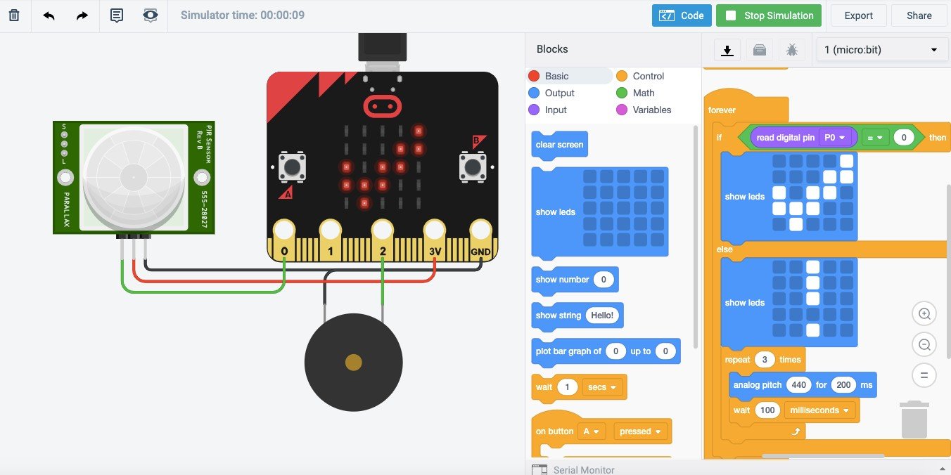
Microbit is the open source software which we can write the programmed in blocks. WEBSITE
The below image shows the programmed in block with same led's will blinking on Microbitchip
 |
|---|
For more details:
The details about Group Assignment
Click here to detail about Group Assignment
About Individual Assignment:
The task for the week in individual assignment is to read a microcontroller data sheet, program your board to do something, with as many different programming languages and programming environments as possible. So here the microcontroller board I am using ATtiny45 IC,which is design and developed in electronis design week.So I had read the datasheet of this microcontroller and also i had done the programming with arduino C++ and Embedded C languagues.
About Architecture:
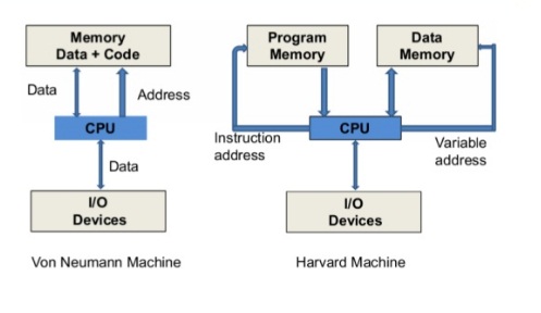
Initially i had started with the basic architecture, Embedded system divides into two achitectures Harvard and von Neumann
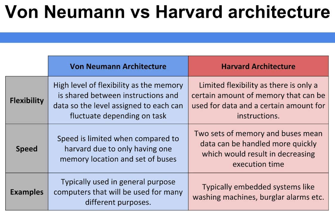
Von Neumann Architecture:
Von Neumann Architecture is a digital computer architecture whose design is based on the concept of stored program computers where program data and instruction data are stored in the same memory. This architecture was designed by the famous mathematician and physicist John Von Neumann in 1945
Harvard Architecture:
Harvard Architecture is the digital computer architecture whose design is based on the concept where there are separate storage and separate buses (signal path) for instruction and data. It was basically developed to overcome the bottleneck of Von Neumann Architecture
 |
|---|
comparison Between Harvard Architecture & Von Neumann Architecture
 |
|---|
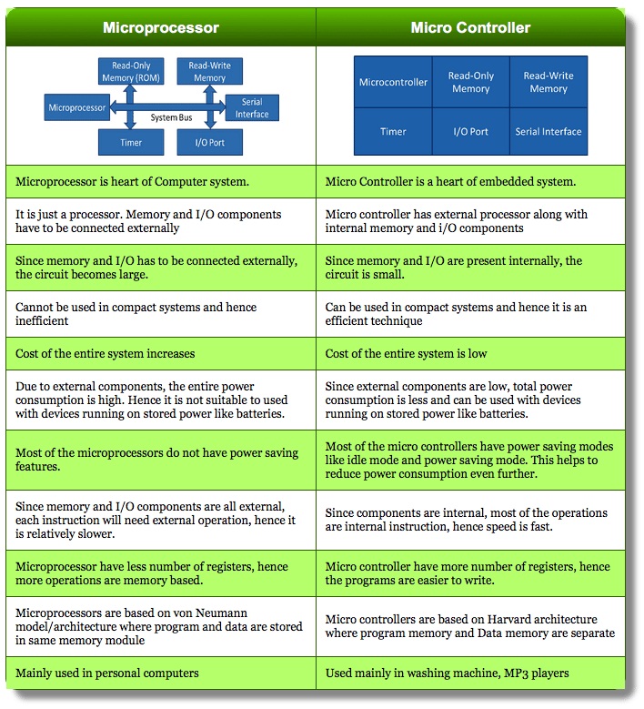
Microprocessor and Microcotroller
Microprocessor :- A microprocessor is an electronic component that is used by a comput er to do its work. It is a central processing unit on a single integrated circuit chip containing millions of very small components including transistors, resistors, and diodes that work together.
Microcontroller :- A microcontroller (MCU for microcontroller unit) is a small computer on a single metal-oxide-semiconductor (MOS) integrated circuit (IC) chip. A microcontroller contains one or more CPUs (processor cores) along with memory and programmable input/output peripherals.
 |
|---|
 |
|---|
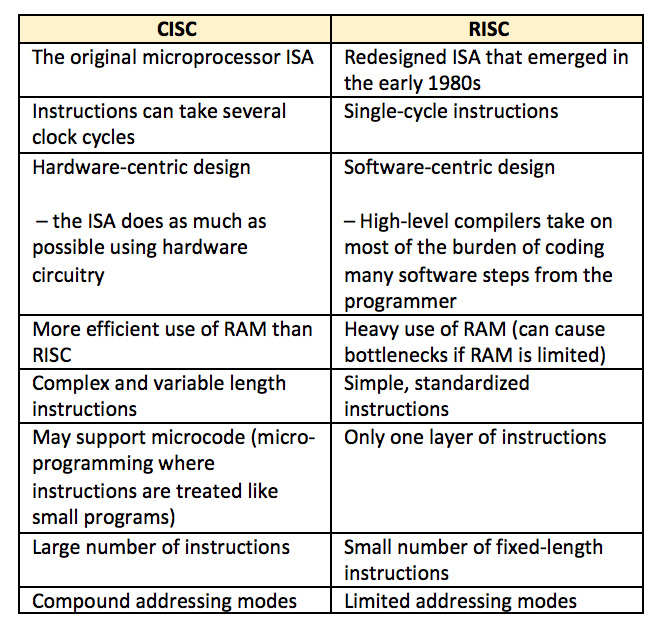
What is RISC and CISC:-
The RISC stands for(Reduced instruction set computing) and CISC (Complex instruction set computing). CISC has the ability to execute multi-step operations within one instruction set. It is the design of the CPU where one instruction performs many low-level operations.
 |
|---|
What is AVR Microcontroller:-
AVR is a family of microcontrollers developed since 1996 by Atmel, acquired by Microchip Technology in 2016. These are modified Harvard architecture 8-bit RISC single-chip microcontrollers. AVR was one of the first microcontroller families to use on-chip flash memory for program storage, as opposed to one-time programmable ROM, EPROM, or EEPROM used by other microcontrollers at the time.
AVR microcontrollers find many applications as embedded systems. They are especially common in hobbyist and educational embedded applications, popularized by their inclusion in many of the Arduino line of open hardware development boards.
Reference:- "Wikepedia"
 |
|---|
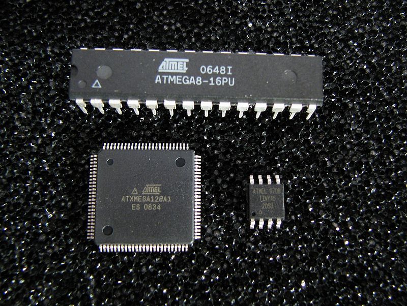
AVR Microcontroller available with 8-pins to 100-pins, any microcontroller with 64-pin or over is surface mount only. AVRs are generally
classified into following:
tinyAVR – the ATtiny series
megaAVR – the ATmega series
XMEGA – the ATxmega series
After understanding the basic concepts of embedded system, i had started with how to read the data sheet of Microcontrroller,So our instructor at Vigyan Ashram introduce us about how to read the data sheet of any electronic component.
So, in electronic Design week i have made Attiny45 microcontroller board and programmed it , in this week again we have to make a our own program and upload it on microontroller board, for that first, I have read the datasheet of Attiny45
What is data sheet
It is a document that summarizes the performance, technical and software characteristics in enough detail that anyone can integrate the component into a system.
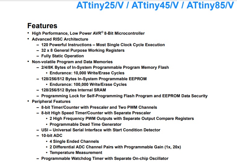
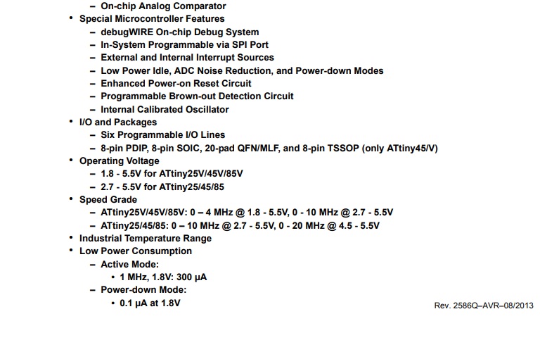
This is the first page of data sheet shows the features of attiny microcontroller Atitiny45
DATA SHEET Attiny45
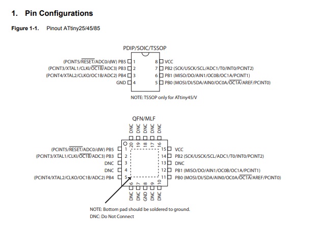
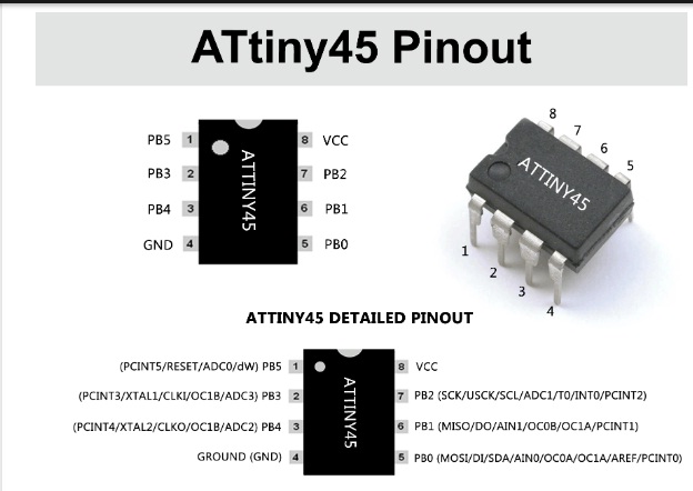
After that i have read the Pin Configurations:
So Attiny45 has total 8 pins out of that 6 pin are GPIO (General purpose input output pins, VCC AND Ground.
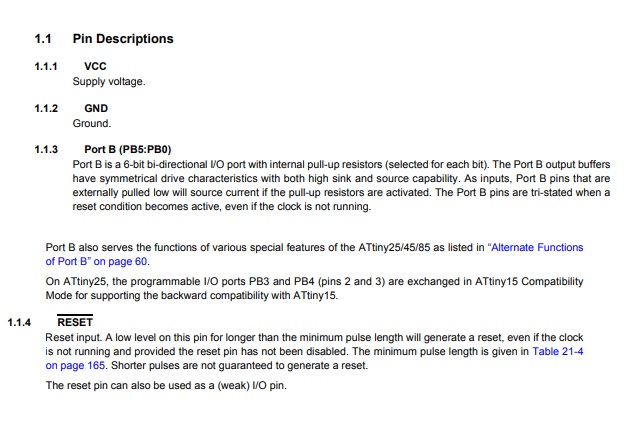
Pin Descriptions:
 |
|---|
In my Attiny45 microcontroller board i have connected the LED to pin. number Pin2 i.e. PB3 and one Switch to pin6 i.e. PB1 (MISO) pin
ATTINY45 Microcontroller Features
|
ATTINY45 –Simplified Features |
|
|
CPU |
8-bit AVR |
|
Number of Pins |
8 |
|
Operating Voltage (V) |
+1.8 V TO +5.5V (ATTINY45V) +2.7 VTO+5.5V (ATTINY45)(+5.5V being absolute maximum) |
|
Number of I/O pins |
6 |
|
Communication Interface |
Master/Slave SPI Serial Interface(5,6,7 PINS) [Can be used for programming this controller] Two-wire Serial Interface(5,7 PINS)[Can be used to connect peripheral devices like sensors and LCDs] Universal Serial Interface (5,6 PINS) [Can be used for communicating with other controllers] |
|
JTAG Interface |
Not available |
|
UART Interface |
Not available |
|
ADC Module |
4channels, 10-bit resolution ADC |
|
Timer Module |
Two8-bit counter |
|
Analog Comparators |
1 |
|
DAC Module |
Nil |
|
PWM outputs |
4 |
|
External Oscillator |
0-10MHz for ATTINY45V 0-20MHz for ATTINY45 |
|
Internal Oscillator |
0-8MHz Calibrated Internal Oscillator |
|
Program Memory Type |
Flash |
|
Program Memory or Flash memory |
4Kbytes[10000 write/erase cycles] |
|
CPU Speed |
1 MIPS@1MHz |
|
RAM |
256Bytes |
|
EEPROM |
256Bytes |
|
Watchdog Timer |
Programmable Watchdog Timer with Separate On-chipOscillator |
|
Program Lock |
Yes |
|
Power Save Modes |
Three Modes[Idle, ADC Noise Reduction, Power-down] |
|
Operating Temperature |
-55°C to +125°C(+125 being absolute maximum, -55 being absolute minimum) |
So From Data-sheet it is clear that the number of pins, (Input/output), The operating voltage range of IC's and some basic information about this Attiny-45 Microcontroller Ics.
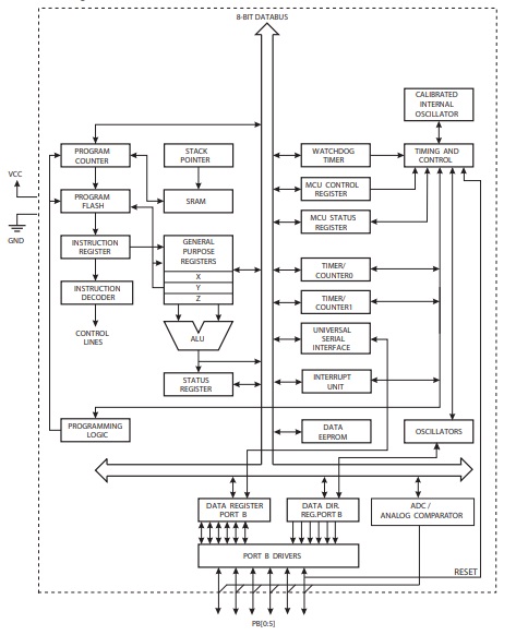
The Block Diagram of Atitiny45
Different Programming Languages In Embedded system
As far as programming languages are concerned, these are the usual programming languages that you often use for building other software products. But you need to learn specific syntaxes and techniques for using these programming languages for programming embedded devices.
The list showing the 18 top embedded programming languages.
1. Python
2. C
3. C++
4. Arduino
5. Assembly
6. Rust
7. C#
8. Verilog
9. VHDL
10. LabView
11. Elixir
12. Ada
13. D
14. Forth
15. TCL
16. LadderLogic
17. Erlang
18. Javascript
Different IDE Used Embedded programming
There are various environment used in embedded programming following are the mostly used.
1. Atmel Studio
2. Arduino
3. Eclipse AVR
4. Fireflybr
5. Scratch
v6. Modkit
There are other ICs too like 32-bit (ARM compatible), AVR in LCD Display Drivers, USB Controllers
Initially,we have started with programming in Arduino with C++ Lanuage, before that we need to installed the arduino software.for this I have reffered Mr. Nikhil More Sir websites
In electronic Design week we have already installed arduino software and required libraries for attiny45, here i worked on arduino with different prgrmming languages
Lets us see what is the bassically Arduino and its Environment
What is an Arduino?
Open Source electronic prototyping platformbased on flexible easy to used hardware and software.
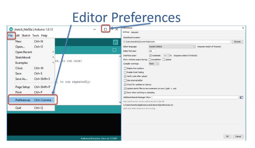
Here, we can installed the required libraries
This shows the default BUILTIN_LED Connected to Pin number 13(Digital)
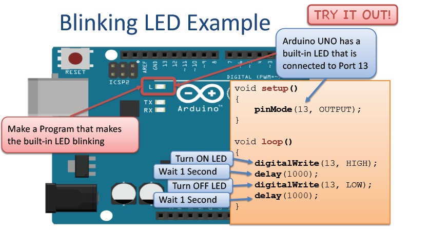
Very First i have tried the programming for IC ATmega328 i.e connected on Arduino Uno Board
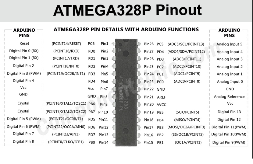
For that, I have reffered Pin the Pin Diagram of ATmega328P pin , it has 20 GPIO pins.and others are power supply pin's
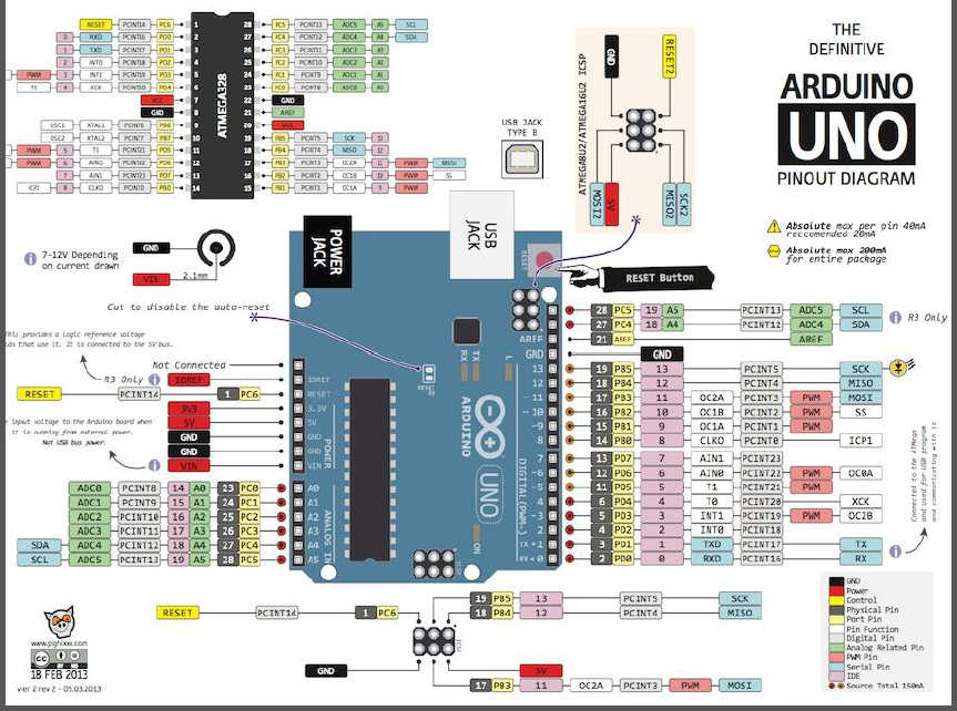 |
|---|
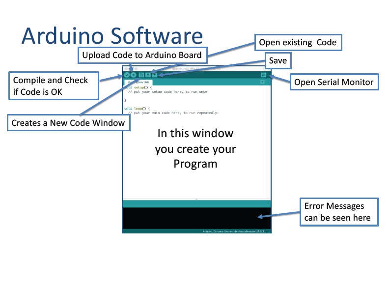
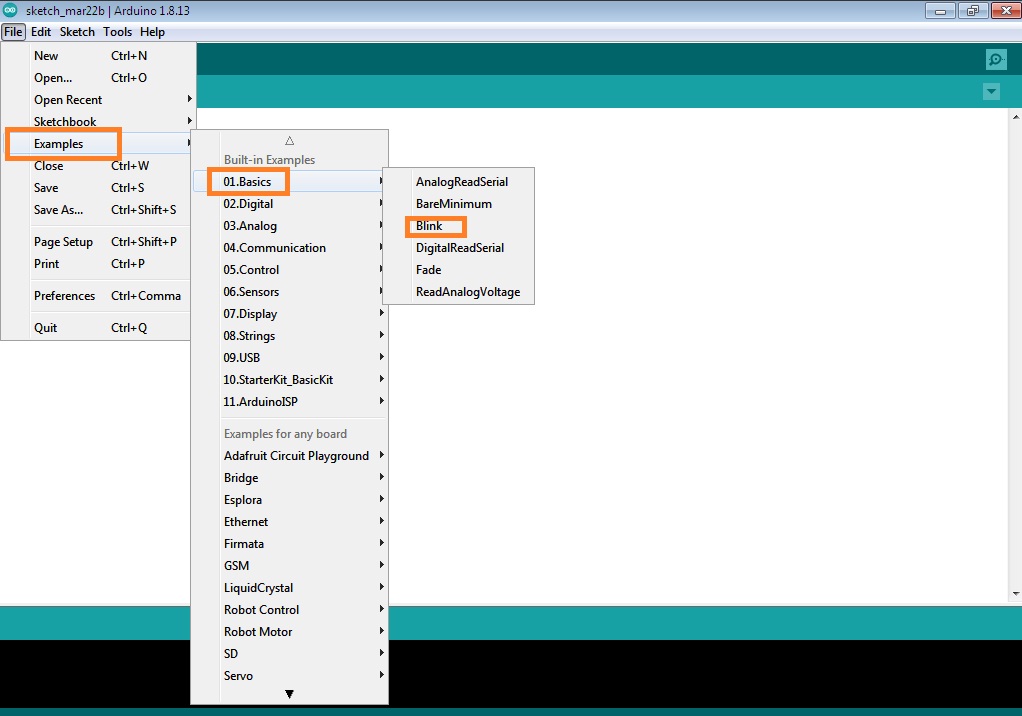
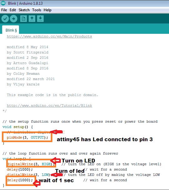
After that i have open the arduino software,In example LED blink program is available,
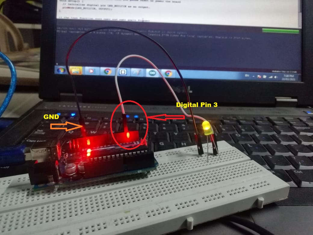
Then i have made the required chnages, As i have connect led to pin 3 (Digital Pin 3)
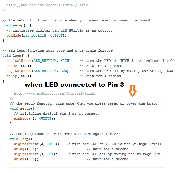
1. void setup()- Void setup is technically a function that you create at the top of each program. Inside the curly brackets is the code that you want to run one time as soon as the program starts running. You set things like pinMode in this section. The loop is another function that Arduino uses as a part of its structure.
2. pinMode (3, OUTPUT);- In this project we are going to blink an LED at port number 3 of micro controller. To blink an LED means, I have to turn it ON and OFF alternatively at a certain interval. So we are going to send commands to turn LED ON and OFF to port 3 of micro controller (arduino board). To do so, we have to configure port 3 as OUTPUT in our program. This is achieved inside the void setup() block.
3. void loop () - The loop is another function that Arduino uses as a part of its structure. The code inside the loop function runs over and over as long as the Maker Board is turned on.
4. digitalWrite(3, HIGH); – This is an instruction to write some data to a particular micro controller port in arduino board. We have connected LED to pin3. To turn it ON, we have to supply a voltage at pin 3. We are going to do that via software commands. Since our arduino board is connected to PC via USB, a +5 volts readily available. We need to pass this voltage to port 3 of arduino board. To do so, APL has a keyword instruction called HIGH. So we just need to write an instruction digitalWrite(LED,HIGH); and this instruction when executed by micro controller will supply a +5 volts at port 13. This voltage will power LED and it will turn ON.
5. digitalWrite(3,LOW); - Now we need to turn LED OFF. We just need to disconnect the voltage supply given at port 3. This command will cut off supply at port 13 and LED will get OFF.
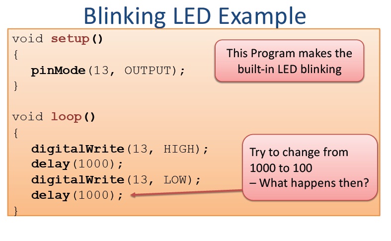
6. Delay (1000); - It is a setting a time interval in between ON and OFF time. The time given for delay is in Milli Seconds.
After that i have tried another programming language i.e. Embedded C on arduino board,Our colleague Mohit introduce about this language and by following him we have tried the below Embedded C Code. For that we have reffered
Make- AVR Progamming by ,Elliot Williams book
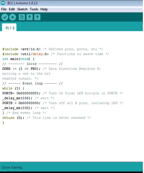
This is the given Embedded C program in book
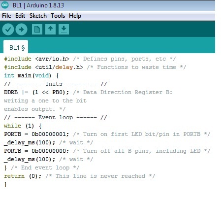
Lets see the stucture of this AVR c code
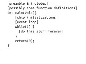
1) First section i.e."preamble section" indicates the installing libraries from other source, we can also define global vari- ables, and define functions.
2) After the preamble comes the main() function. The name “main” is special—re- gardless of how many other functions are defined, your C program must have ex- actly one main() function. main is where the AVR starts executing your code when the power first goes on. It’s the entry point.
3) Inside the main function you’ll find a while(1) loop, often referred to as the “main loop” or “event loop.” while() loops are loops that continue running over and over as long as the condition inside the parentheses is true. And in C, 0 always resolves as false, and 1 always resolves as true. So everything that’s within this loop will run over and over again forever. As long as you’re giving the AVR microcontroller power,
4) why Return (0):-
In C and C++ programs the main function is of type int and therefore it should return an integer value. On most operating systems returning 0 is a success status like saying "The program worked fine". In C++ it is optional to type " return 0; " at the end of the main function and the compiler includes it automatically
5) Now, switch on actually what something done in the code
As we know the arduino has 3 ports PORTB (PB0-PB7), PORTC(PC0-PC7) , PORTD(PD0-PD7).
6) DDRB- Data directions Register B: Means whatever you apply the logic on this port it will strore in register B .i.e DDRB and PORTB are definitions that point to the AVR’s internal hardware registers.
7) DDRB |= (1 << PB0); means, if the PB0 is set to output. The DDRB |= 1 << PB0 is used.
The DDB0 - is now set as output and the bit is set to high or 1.
OR
If I will clear that bit like mentioned DDRB &= ~(1 << PB0).
this means the DDB0 is set to a low level 0 and now it is declared as an input.
This be an equivalent to clear the PB0 bit:
DDRB = 0b00000000
PORTB=0b00000001:- Means turn on the first LED connected to port B (PB0)
PORTB=0b00000000:-means send the logic low at port B(PB0)
_delay_(100):- means wait for for 100 milli second
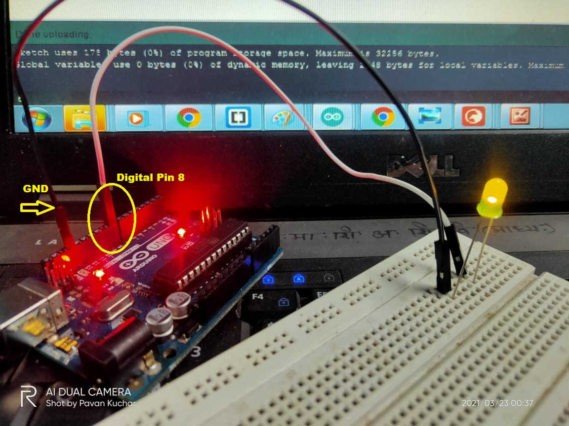
Once coding is done I have reffered the pin out of ATmega328p IC and found there PB0 pin is connected to Digital pin no. 8 of arduino board, So here i need to connected my led at same pin
There are two steps involved in loading the program from your PC to arduino board via the arduino IDE. First step is compiling and second step is called burning. Let’s see in detail.
1. Then complile the program first, Compiling a program is the process of transforming high-level source code into a low-level object code (binary code) called machine language, which can be understood by the processor. In Arduino IDE AVR-GCC Toolchain is used for compiling the program.
2.Uploading – uploading a program to any micro controller. So in this step, we are going to upload the verified program in arduino IDE to the arduino board. To do this, press the “upload” button (see the button with right arrow mark). A click on the “upload” button will begin the process of burning the compiled program to Avr micro controller on our arduino board. Depending on the size of our program, this will take a little time. If we look on our arduino board, we can see the 2 LED’s near Tx and Rx blinking. This is an indication of successful communication between your PC and arduino board. If the program has been uploaded successfully, we will see a message like “Done Uploading“. If the uploading process was not successful, you will see an error message.
Here, I had faced the problems while uploading the program its gives the error
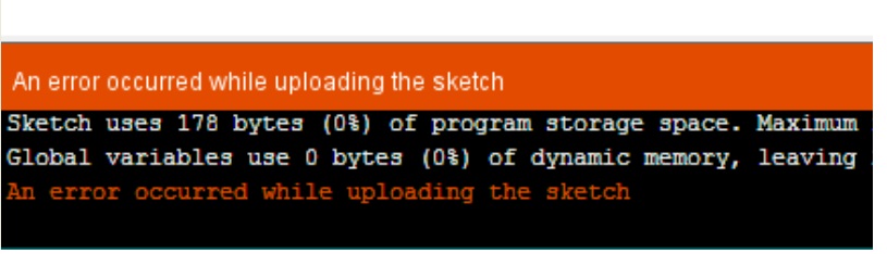
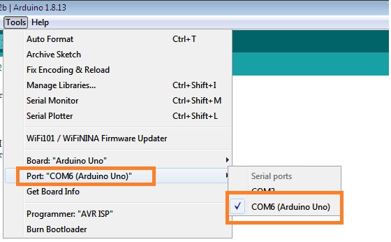
So In this case i need to disconnect the Arduino USB port and connect properly and also checked the COM port is detects or not
After that uploading the program is done successfully, then i connenct LED to PB0( Digital Pin no. 8), its blinking as per programmed
In this way I have cheaked the the same program for various combinations of ports and pins also
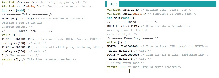
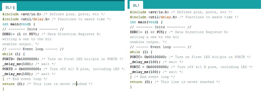
Note:-In this case, it is observed that when i changed the ports and pin, i need to change the binary code of register accordingly
For eg;- Suppose we take DDRB |= (1 << PB2); We need to write binary code or logic 1(high) to bit number 2 i.e PORTB=0b00000100.
(Apply same above logic to other oprations)
After that I have applied same programming on my echo hello world Atitiny45 Microcontroller Board
Before that i had read the pin configuration Attiny45 Board
In electronics Design Week i have made echo hello world Attiny45 Microcontroller board on that, LED with current limmiting resistor connected to pin number 3 (PB3)
So here first, i have tried Arduino programming on this board
When i connect, Attiny45 to my laptop as discribed in previous week documentation we need to installed required libraies and board manager This process i have already completed in last week(Electronics Design)
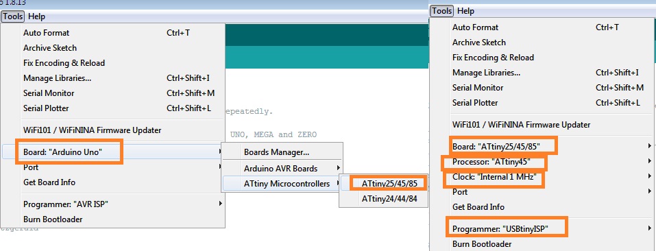
Once you configure the Attiny45 Board properly with arduino IDE then you can compile or upload your programmed other wise its gives the error like below ,that i have faced while uploading my program
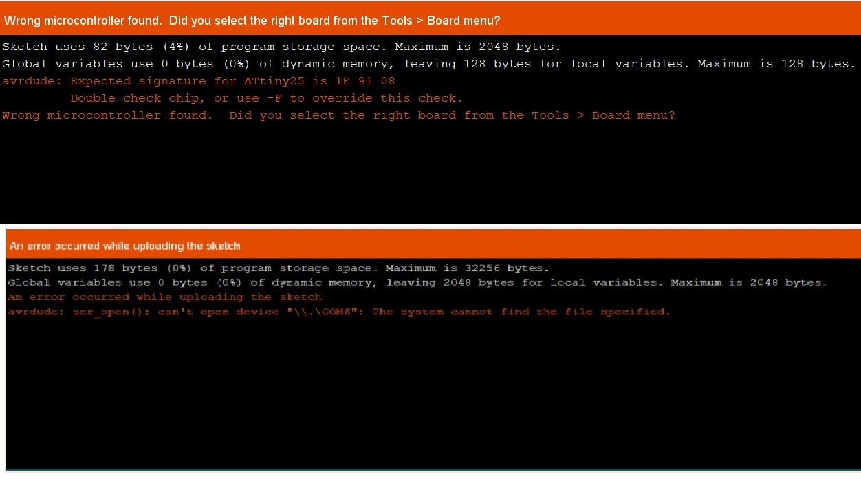
Then I have Edit my programmed as per attiny45 Board and upload it by making respective changes in given example in arduino IDE
The LED connected to attiny45 Board at pin 3 is blinking
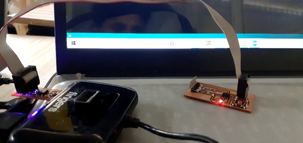
The video shows blinking of LED as per given code.
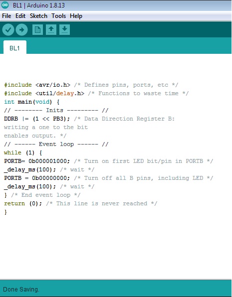
Embedded C language Program Using Arduino IDE
Now, have tried using C language for the LED blinking on ATTINY 45 Micro-controller board. The objective of the work is to learn the command use in C-language as we have discussed above.
The program is as follows:
This is i made repective changes as per LED Connection
Then make the connection as per need and follow above process for configure arduino IDE
After uploading the program on attiny 45 the LED is blinking
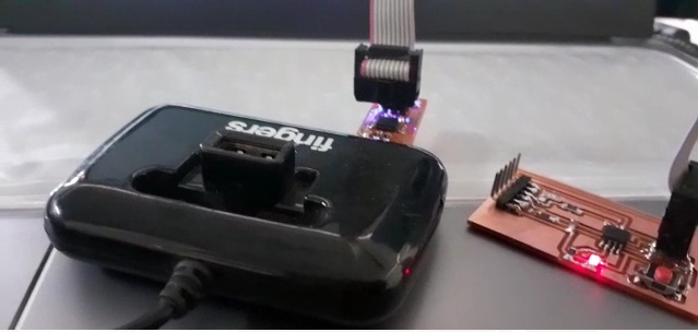
The programm is uploaded successfully in the board and LED will blinking. Lets see the video.
This case i have set the delay 100 milli Second, so its decreases the ON time as well as OFF time of LED thats why LED blinking speed is increases.
Summary:-In this week of assignment we have succesfully done the programming (Arduino C++ and Embedded C) of different languages with different IDE.
We have also programmed Echo Hello World attiny45 Microcontroller Borad.
What i have learned:-
1. learned about the basic concept of Embedded System
2. How to read the data sheet Attiny45 Microcontroller Board and why it is neccesary to read it.
3.I have learned about the arduino uno board and it's Integrated Developement Environment.
4. Arduino board coding using C++ language.
5. learned about Embedded C coding for blinking of LED with different combination of ports and pins.
6. How to programmed Attiny45 Microcontroller board with arduino IDE.
DOWNLOAD's
Download my original file here