Task to be Perform for this week
1) Group Assignment :
The task for the group assignment is to test run out, alignment, speeds, feeds and toolpath for given machine ,Document your work (in a group or individually)
2) Individual Assignment:
In case of Individual assignment The task for the week is to make (design+mill+assemble) something big using CNC Machine
So here in this assignment Prof. Neil suggest to use ShopBot Machine to cut a plywood material and develope a furniture on it which is helpful for Fab Lab.
Learning outcomes
Demonstrate 2D design development for CNC production
Describe workflows for CNC production
Introduction to computer numeric control (CNC Machine)
A CNC (computer numeric control) tool is used in prototyping and full production for cutting, carving, machining and milling in a variety of materials including wood, mdf, plastics, foams and aluminum.
With a ShopBot CNC tool, you use the included software to design your parts on your personal computer, then, like a robot, the computer controls the cutter to precisely cut your parts.
In the past, CNC tools were strictly industrial tools only used in large factory settings. Now, all the types of computer-driven tools that create things by cutting material away (such as CNCs or laser cutters) or building up material in layers to create an object (3D printing) are called digital fabrication tools. ShopBot's innovations in CNC technology have made these powerful tools affordable for individuals and small shops.
We make CNC tools for every situation imaginable, right down to completely customized machines designed to fit your exact specifications. Whether you’re looking to boost small business production, prototyping, or factory-level fabrication, there’s a ShopBot for your needs.
Source
Features of Shopbot CNC Machine
1. Fast, closed-loop Vexta alphaStep motors fitted with low-backlash, tapered-hob gear heads on all three axes (two on the X axis) -- alphaStep system monitors motor shaft positions to maintain synchronicity between signal and motion.
2.Tough precision linear bearings on the moving gantry and hardened steel rails for the x-axis.
3. Reliable rack-and-pinion power transmission on each axis.
4. Impressive cutting speeds of up to 600 inches per minute (depending on cutting bit and material) and rapid transit speeds of 1,800 inches per minute.
Step resolution of .0004”.
5. Positional accuracy of +/- .002”.
6. Sealed Industrial UL Certified Control Box.
7. Emergency Stop disconnect switch in the Control Box with integrated and cabled remote Emergency Stop Buttons.
8. Z-zero Touch-Off Plate and XY Proximity Switches.
9. ShopBot Control System software to run your CNC.
10. Dust Skirt ready to connect to your dust collector.
11. Each new ShopBot tool includes powerful design software to create to create CNC projects.
12 .Shipped as four ready-to-assemble modules. On-site assembly and training available.
13. Free Tech Support and User Forum.
Two-year warranty.
For knowing the details about shopbot Machine i had reffered this website
shopbottools.comAbout Group Assignment:-
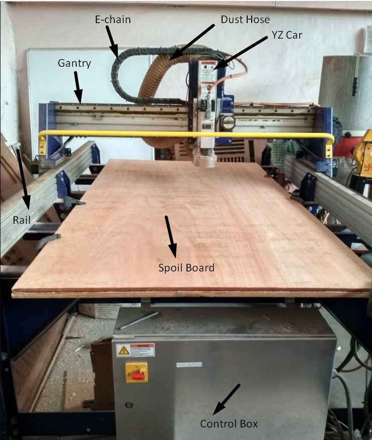
The task for group assignment is to test runout, alignment, speeds, feeds, and toolpaths for our machine. So Fablab at Vigyan Ashram We dont have shopbot machine for completing this assignment we had to go and perform the at college of Engineering Pune (COEP).
At COEP college ShopBot PRSalpha is availble.
It is having three axis X,Y,Z CNC router machine
It is made for CNC cutting, drilling, carving and machining.
The Shopbot Machine of Fab Lab, COE Pune has following specification:
Sheet Material up to Size: 4 Feet x 8 Feet x 6 inch in x,y,z direction resp.
Table Size: 6 Feet x 10 Feet
Step Resolution : 0.0005 inch
Positioning Accuracy: +/- 0.0005 inch (No Load)
Cutting Accuracy: +/- 0.015 inch
Simultaneous linear interpolation: 3 Dimensional
X,Y and Z axis drive system: Rack and Pinion
Impotant parameters of Shopbot :
Feed Rate :
It shows that how fast the machine will move the router bit through the material (in this case the plywood of reuired thickness) when we give the cutting pass. It is very important to for getting good quality cut edge.
Plunge rate :
It is the speed at which the router bit is driven down into the material when we start cutting and it will vary depending upon the bit we have used and the material on which we are going to process.
Spindle speed :
It is the speed at which the tool revolve around Y direction. Feed rate and Spindle speed are inter-related. Sometimes it is possible to cut at a faster feed by increasing the spindle rpm. Similarly, if we cut the material at too low feed rate or with too high spindle speed there is a risk of overheating of the router bit and also burning of material get happen.
Step over :
It is the maximum distance in the x/y direction that a cutting tool will engage with uncut material
We had Introduced about the machine and its different part one of our instructor Miss Apeksha Bochare Madam,
After that We have tried generating toolpath of design.
Due to the Pandemic situation (Covid) , we had remotely accessed the tools and we have generated the tool path using partworks software with the help of anydesk tool
After the design of the our Object, the scaled down version was printed on the Numac Hitech machine.
Art Cam Pro and NcStudio Softwares were used for the toolpath generation.
About Individual Assignment:
In individual assignment Before going to design the object i have reffered previous object designed by Fablab students., As we make somethis big i had gone through google for different object design.
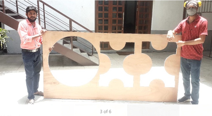
Finally I had tried to design tea table of using freecad software,generate the toolpath using partwork software and mill it by using shopbot CNC machine.
I had used 12mm plywood material.
Parametric CAD Design in free Cad Software
As we have told our design should be parametric becuase,
In Parametric modeling is an approach to 3D CAD in which you capture design intent using features and constraints, and this allows users to automate repetitive changes.
For my Individual Assignment, I wanted to make a furniture that is simple by using wood minimum as possible. So I thought of making a tea table.
For design the my object i have used free Cad Software. i have develop tea table which is helpful for our fablab.
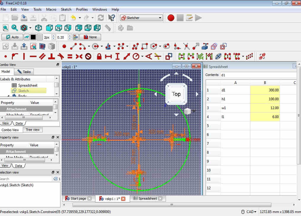
Basically Object is divided into three part, first i have design separate parts and then assembled it using the assembly workbench. as i had to design the parametric object, so i have used spreadsheet, because if need to change the dimmession as per requirement that i can be easily changed.
The detail of my design as shown following
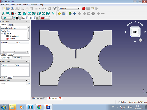
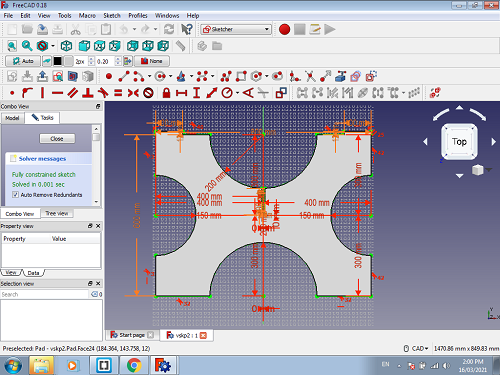
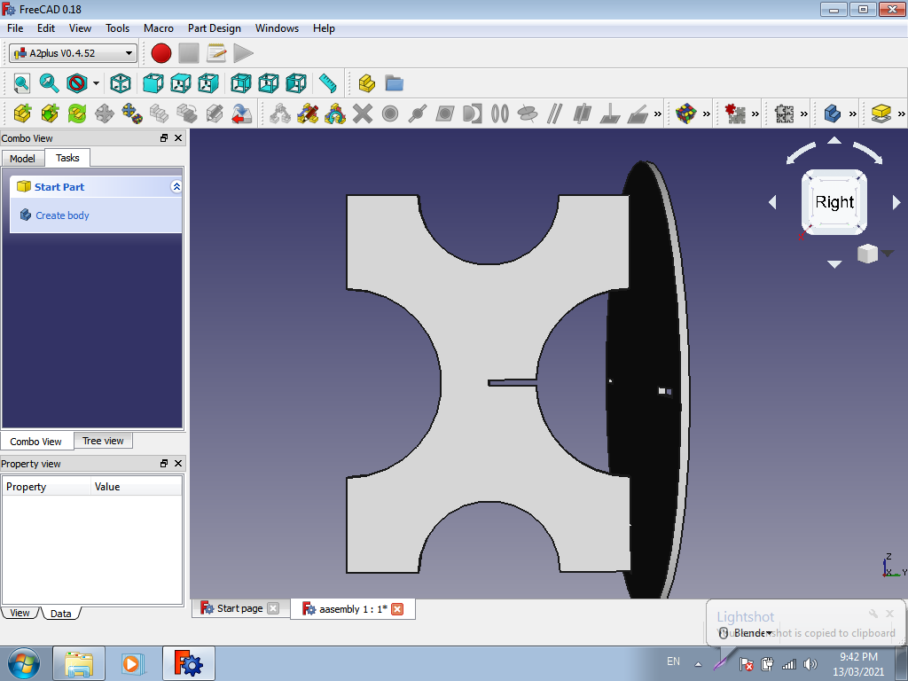
This is the first part of my design using skecher Workbench
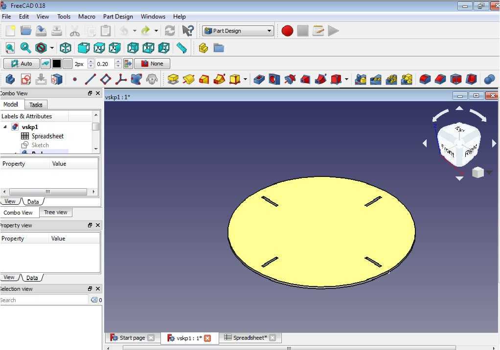
Then i had make it 2D Object into 3D by creating the body and pad it in part design Workbench
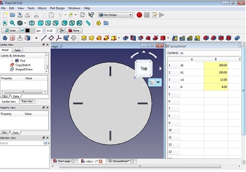
This is the top portion of my design
Now, i have developed the second part of object in same way(Base Portion of design)
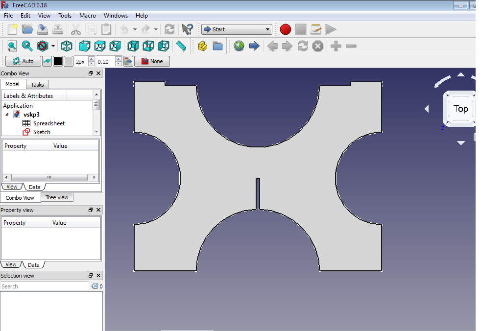

Here, the design is completed in separate parts,
After That I need to go for the assembling this part.
Initially assemly workbench(A2plus) had not readly availble i had to installed this workbench from website
Steps for adding the assembly workbench in freeCad
.
1. First go to website A2 Plus
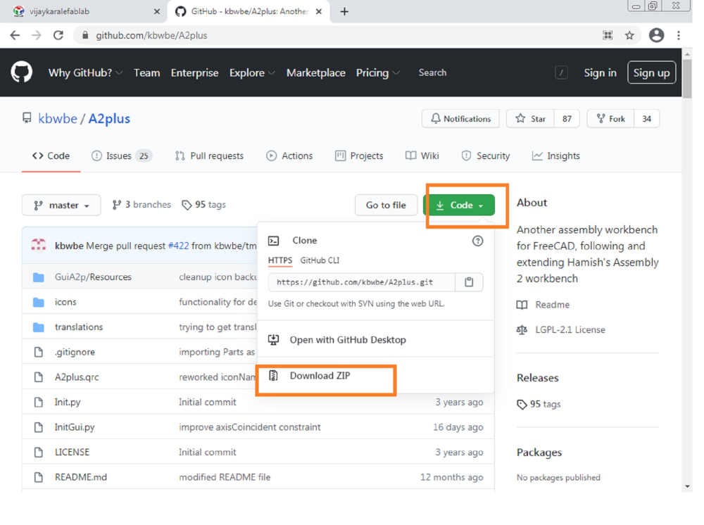
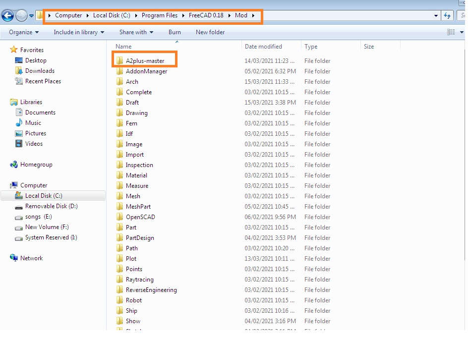
After that download this code as a Zip files and Extract it to free CAD software in FreeCAD Mod directory.
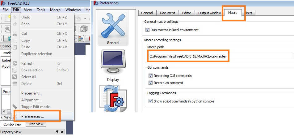
Then open the freecad software go to Edit menu ->> Goto Preferences --> click on micro and checked Here the A2plus Workbench added succesfully in your software
After That restart your FreeCad Software and checked this workbech is added in your menu
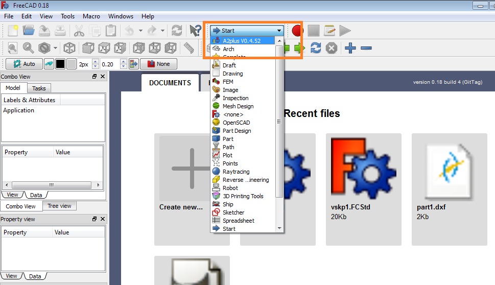
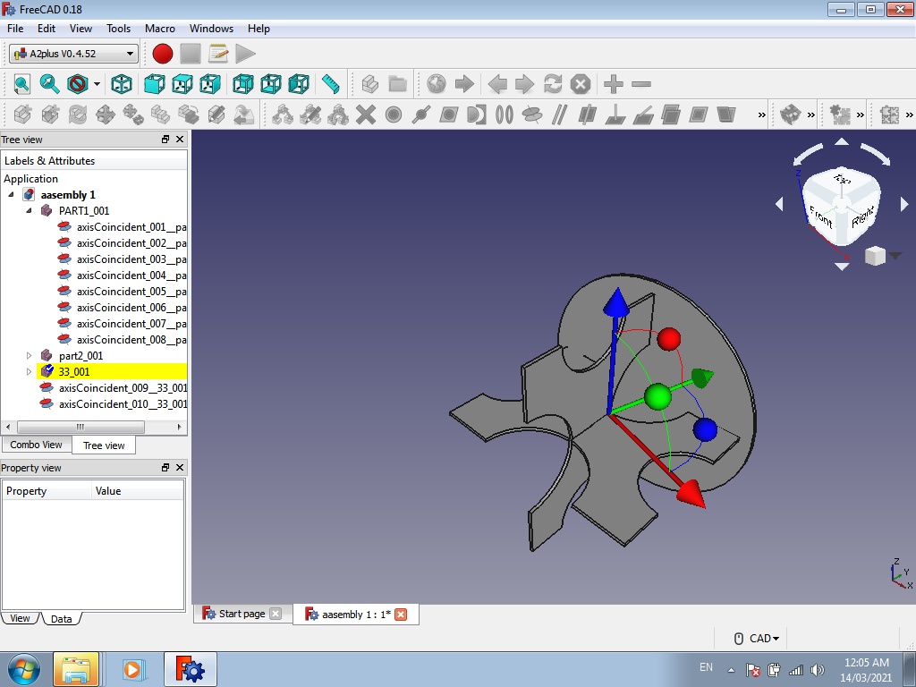
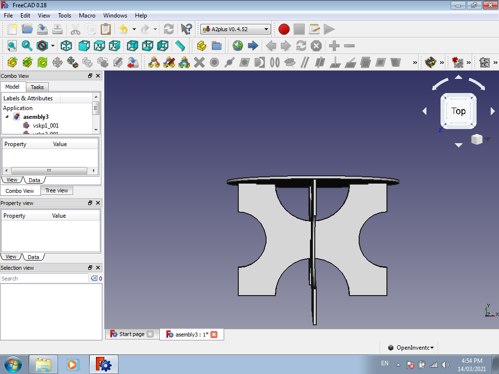
After Installing this A2 plus workbench in freecad i assembled the part of my object
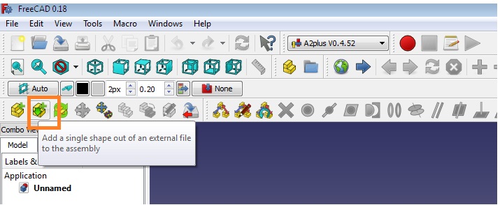
First I need to , switch to the A2plus toolbar in FreeCAD.
To create an assembly create a new file in FreeCAD.
At first this file needs to be saved. if possible save it at same location where your previous part saved.
Now, I had added my part in Assembly Workbench using toolbar button
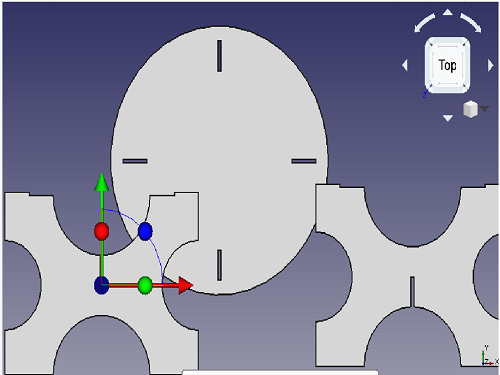
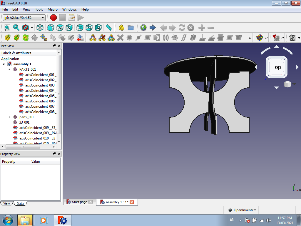
After Importing the all parts place them properly in bed area
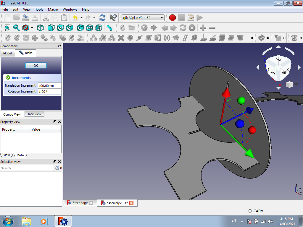
After that we can move the each part by seleting it and using move tool.
You can move the parts in various directions and along the axes by using the arrows and the Red, Blue or Green colored
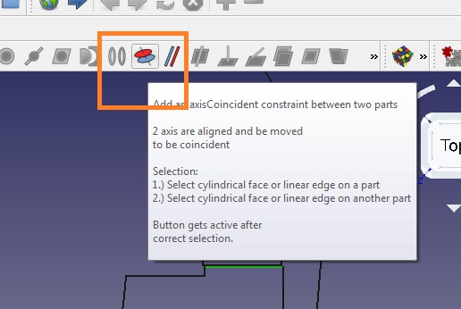
Once your parts are arranged with each other, you can go for better better align the edges with the help of Alignment using this alignment Constraint.
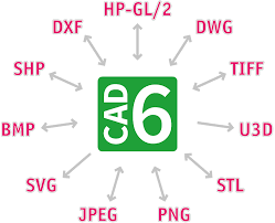
After that we need to convert this 3D file into 2D , these are various 2D file formats.
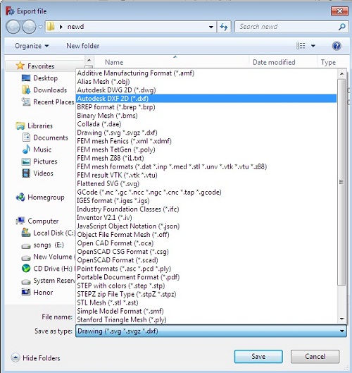
Creating the .dxf file for Milling using Drafts Workbench:
For Generating the toolpath we need to save this design file in .dxf Format.
I have save this file in .dxf format using Draft workbench in free cad
Initially i tried to export this design file in .dxf format but there was giving some error i.e. file format is not supported for exporting, Here i had faced problems while converting this 3D object into 3D.
After that i had gone through google "how can convert 3D files into 2D i.e. .dxf Format,reffred some you tube videos in that i found, we need to installed Draft-dxf-importer-master,
So i have downloaded this and extract this files into "lib" folder of freeCad Software still it was not working
Installed
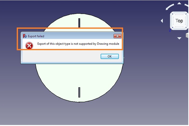
Then, I tried saving this file in flattened .svg file format, here again something was going wrong may be from my side and it not properly saved, this is some what looks like this
Finally I saved the file as Autodesk 2D.dxf format and it was done successfully .
Once your .DXF file is ready, go for generation of toolpath using parts works software
As discussed above due to pandemic situation we have remotelly access the partworks software with the help of Anydesk tool
What is Computer Aided Machining
The CAM machining divided into three parts
1. Software
2. Machinery
3. Post Processing.
For machining and generation of toolpath by using Partworks software is used , ShopBot Machine is used for plywood milling i.e. cutting.
4.ShopBot machine software is used for converts toolpaths into a language machines can understand. so we will discuss it one by one
Generating The Toolpath of design using partworks Software.
About partworks software
Partworks is a software ,which required to generate toolpath and to generate gcode and that file given to machine another SHOPBOT software is used.
PartWorks is a CAD/CAM program that will get you started quickly designing for CNC cutting and machining. This 2.5D design system has a highly acclaimed interface that makes it easy to get your ideas and designs ready for your ShopBot to cut.
For knowing more details i have gon through below links
here
here
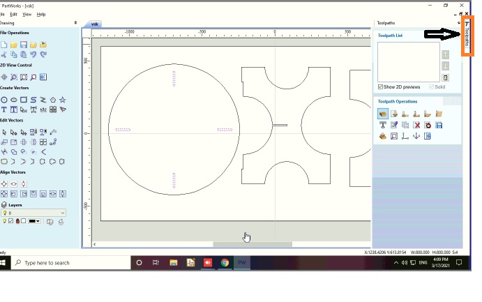
Steps for generating the toolpath in partworks
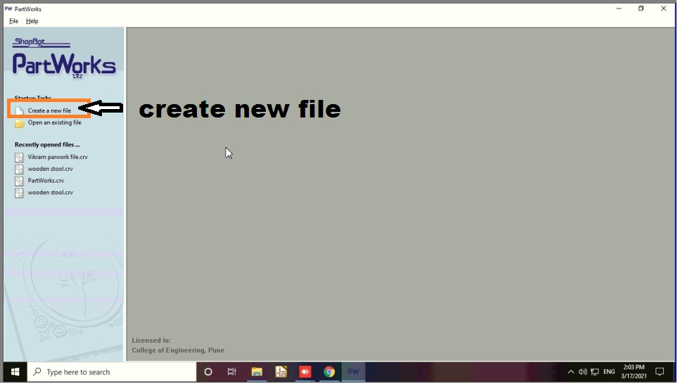
Step 1. Open Partworks and click on create new file
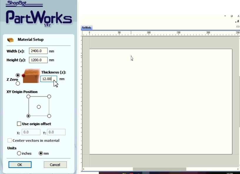
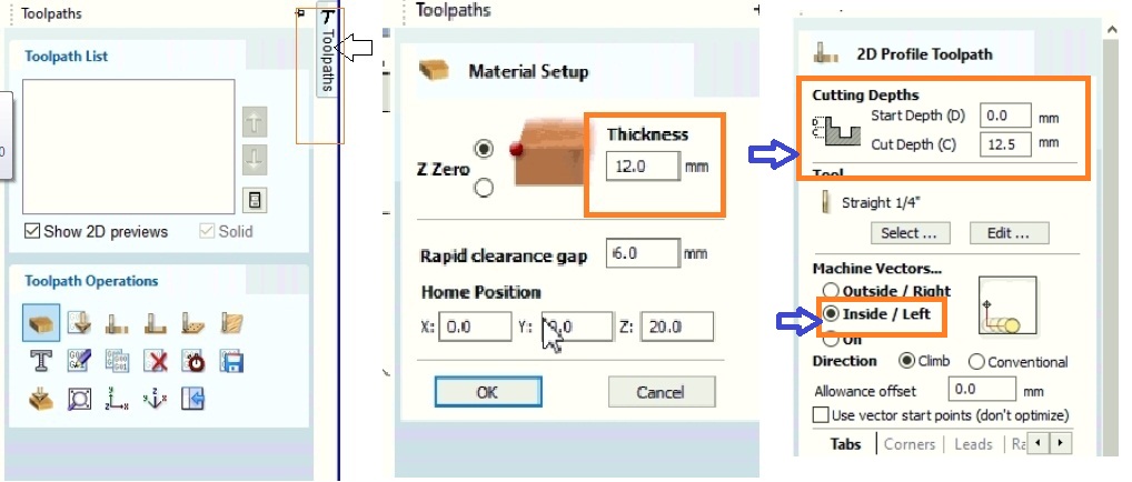
Step 2. Set the size of your sheet as my sheet is of 2400*1200 so i put this dimension in that and set material z zero at at top and material thickness of 12mm
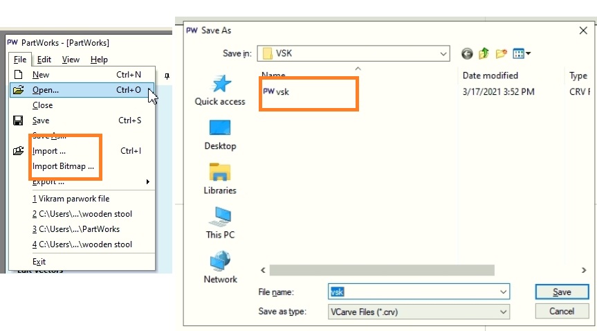
Step 3. Go to file option and click on import or import vector from here i.e dxf file which you made for cnc
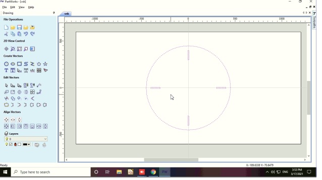
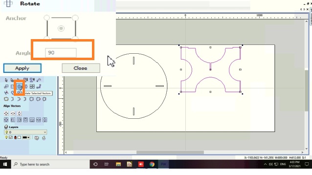
After that i have imported the another parts of my object and rotate it at an angle 90 degree using rotate command
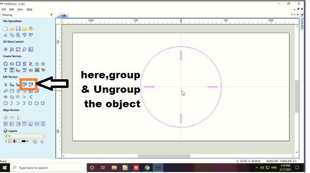
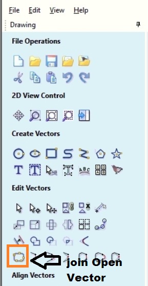
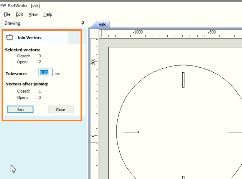
Step 4. Now join all the open vector using join command in last row and first column of edit option so it make close boundary of your vectors.
Step 5. Select inner profile of drawing and go to toolpath and select create profile toolpath on this the setting i keep for tool and cut depth to 12.5mm,
so select the cutting depth of the tool, here i am using 12 mm sheet, so set depth by 0.5 mm is extra, because in case plywood the thickness is not constant so here the cut depth is 12.5 mm.
Select the tool, here we are using 1/4 inch tool. Then select the machine vector, it will decide the toolpath and then press calculate.
Machine setting for toolpath
1) 2D Profile toolpath
Start Depth = 0.0 mm
Cut Depth = 12.5 mm
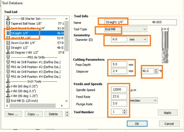
2) Tool- straight 1/4"
Tool type - end mill
Diameter - 6 mm"
3) Cutting Parameter
Pass depth - 5mm"
Step over - 2.4mm"(40%)
4) Feeds and Speeds
Spindle speeds = 12000 rpm
Feed rate = 27.0 mm/sec
Plunge rate = 3.0 mm/sec
Tool Number = 1
5) Machine vectors- Outside/Right
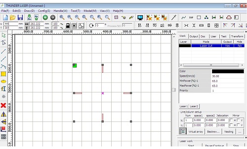
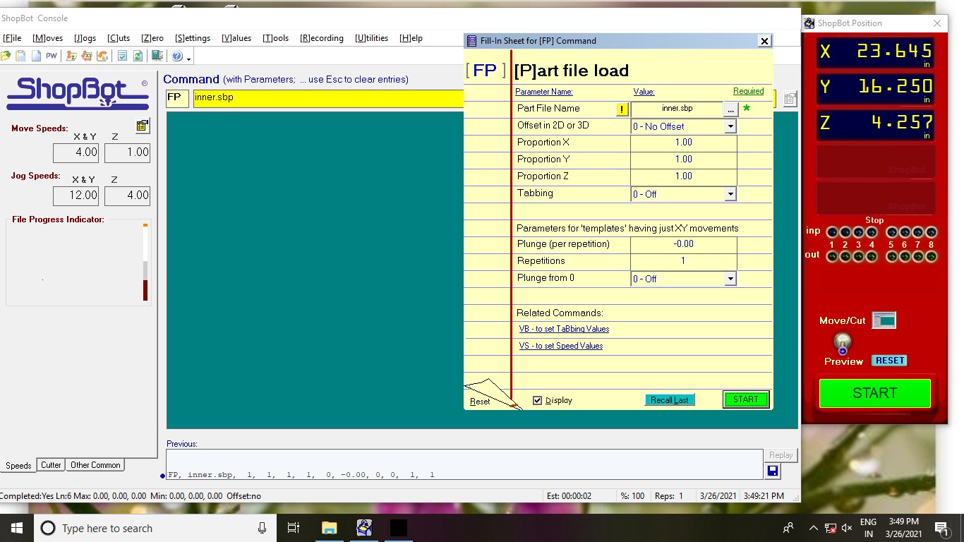
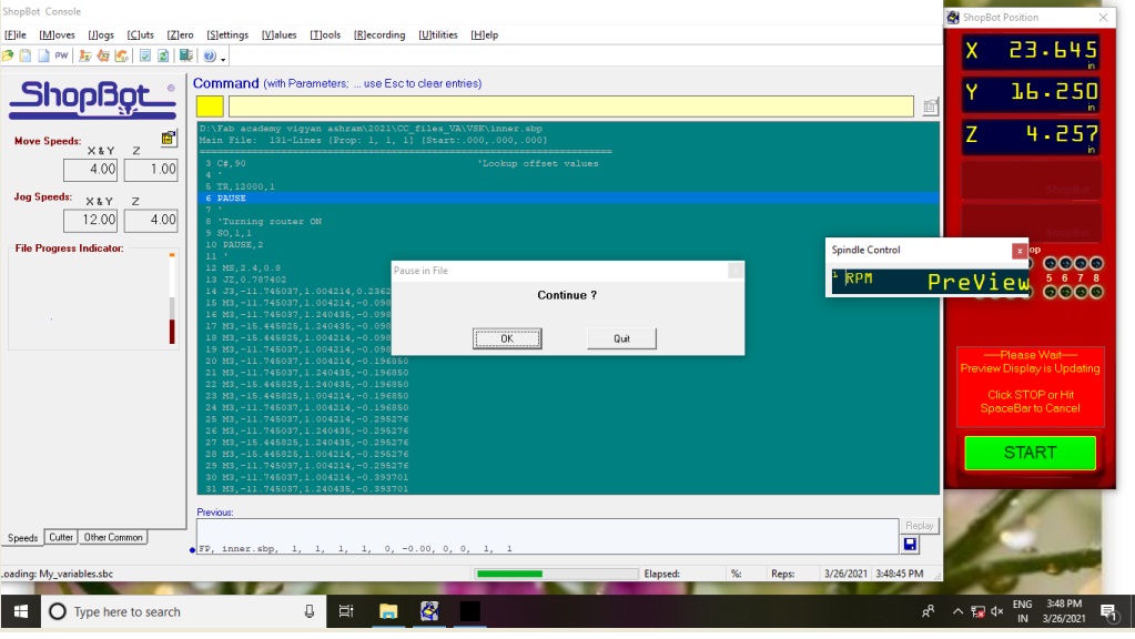
Below Image shows the Parameter setting of Shopbot Machine
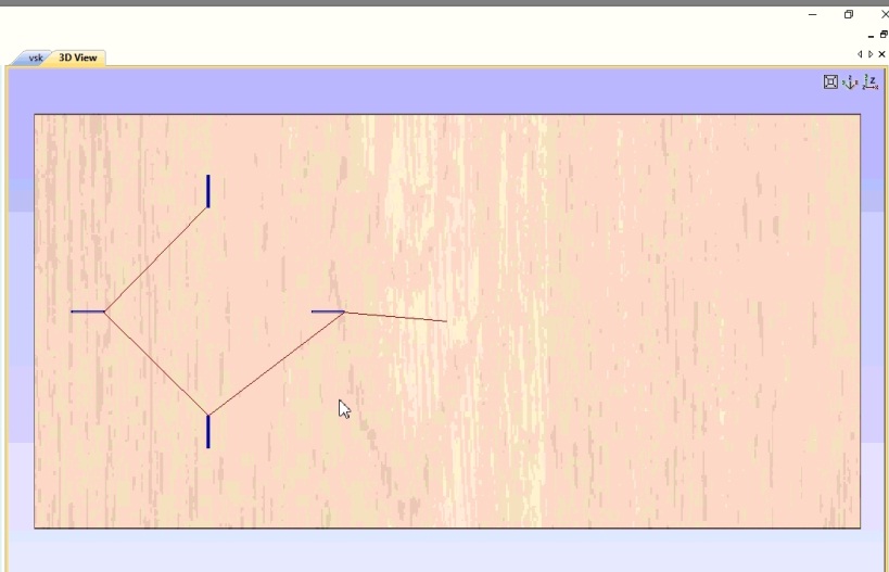
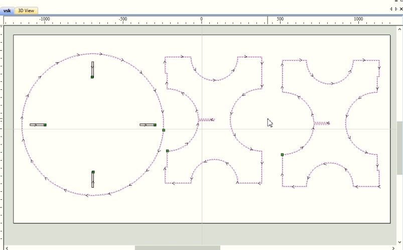
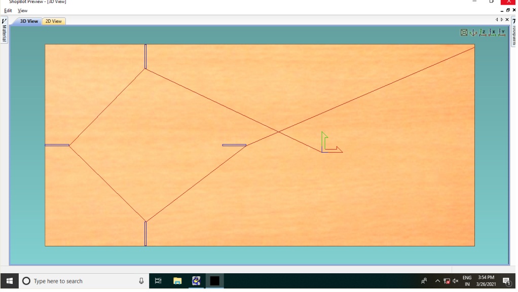
Below Image shows the toolpath of Inner Design
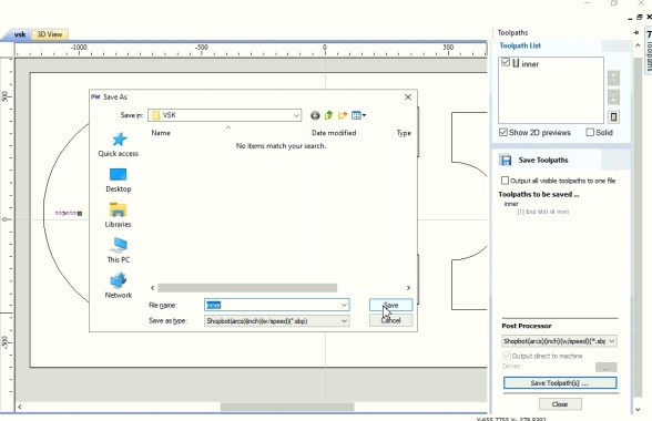
Below Image shows saving the Inner Profile
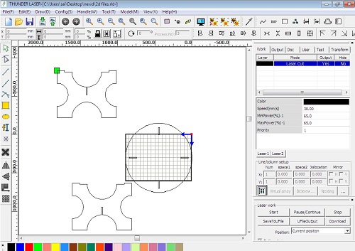
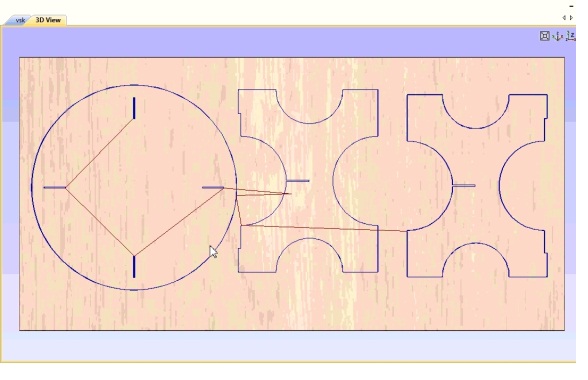
Below Image shows toolpath of whole Assembly
Such a toolpath is generated, after that save the toolpath
Next step is used of shopbot machine for cutting this designed.
Machining On Shopbot
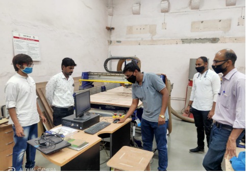
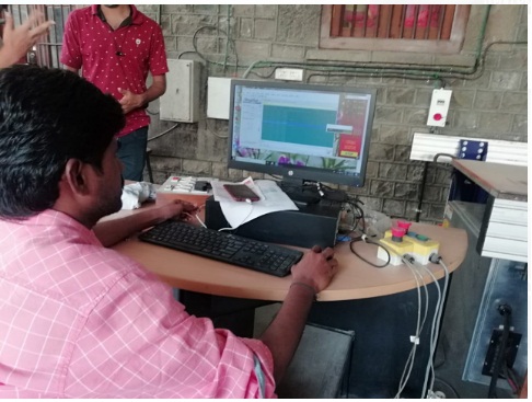
Before work on this shopbot machine we have been taught hand-on experience on How to operate the machine at COEP college Pune.
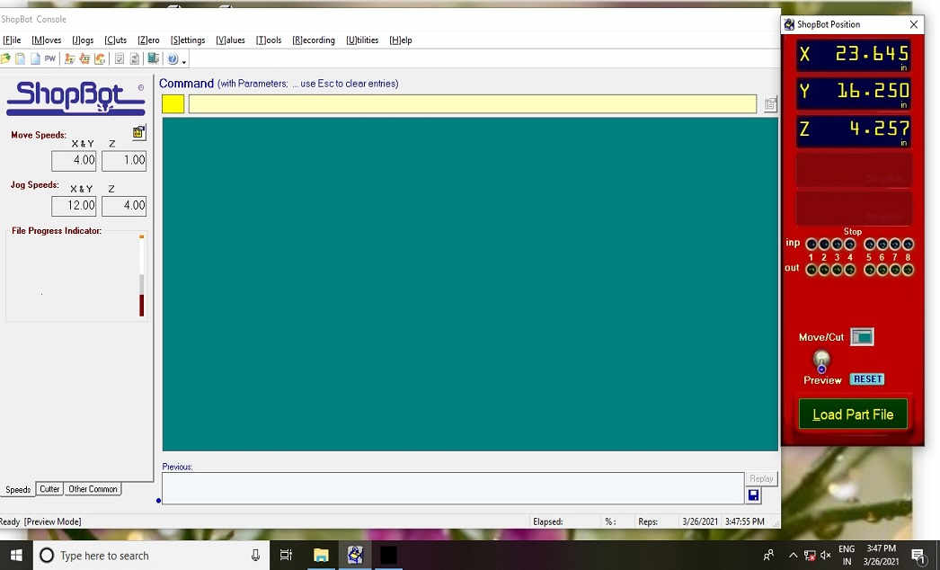
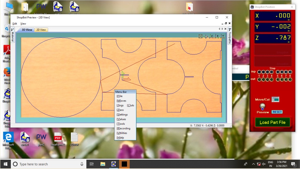
The opening window of Shopcontrol software is used to control the Shopbot CNC tool.By using its different commond we can move the tool and cut the object.It uses the .sbp file.
The opening window of Shopcontrol software is shown in the image.
Click on the Shopbot keypad to set the origin X,Y,Z as per requirement.
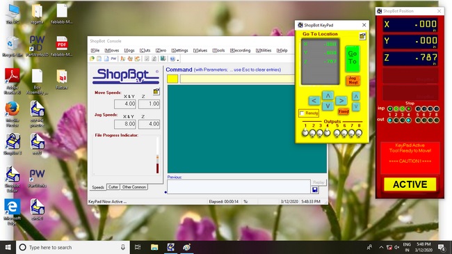
Used the keypad ,move the spindle over material and set the origin as zero.
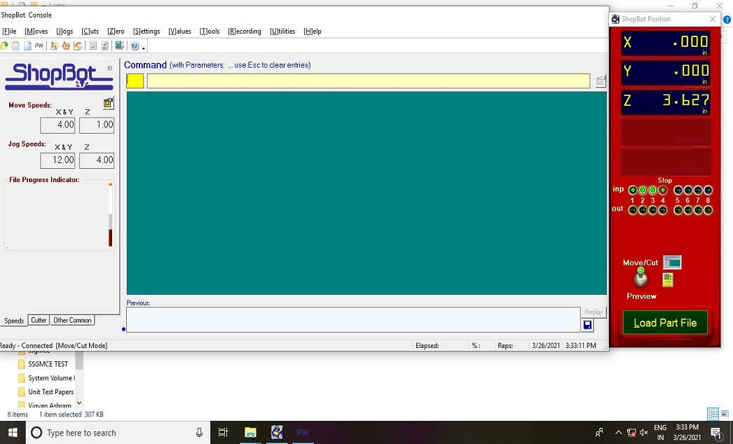
Now load the file, machine is ready to cut the part file,make sure that everything is fine.Turn on the machine with on switch.Turn on the spindle and vacuum.
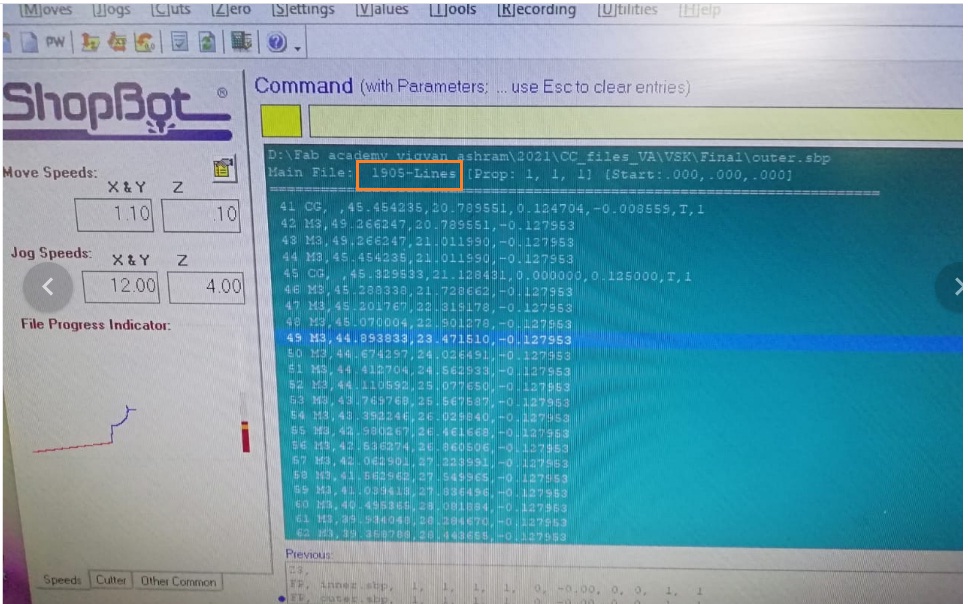
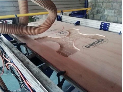
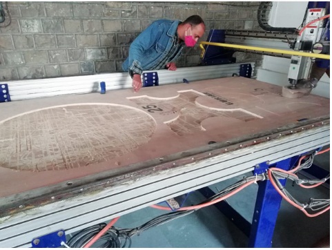
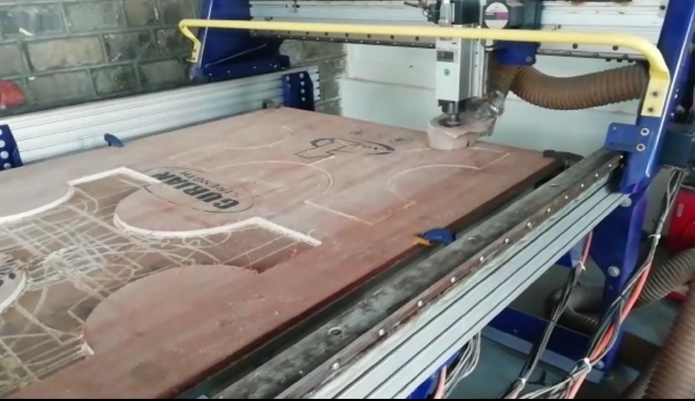
Below images I have click on while operating the shopbot machine.
Then we need to Set the plywood on the scrificial layer(machine bed).
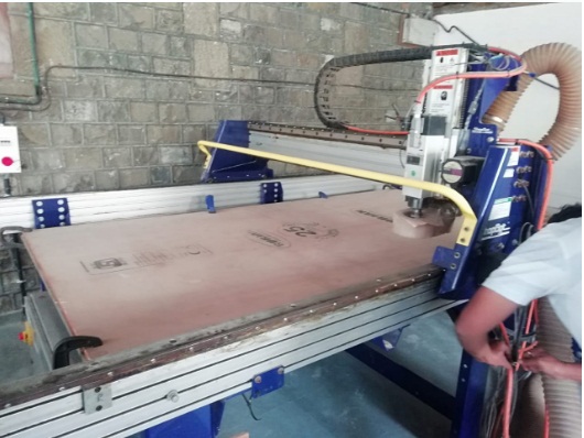
After that hold the properly sheet on the machine bed.
Then Machine start cutting the plywood according to inner tool path and outer toolpath.
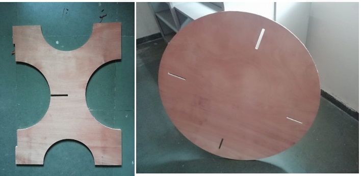
This is how machine cutting the all designed parts one by one.
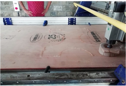
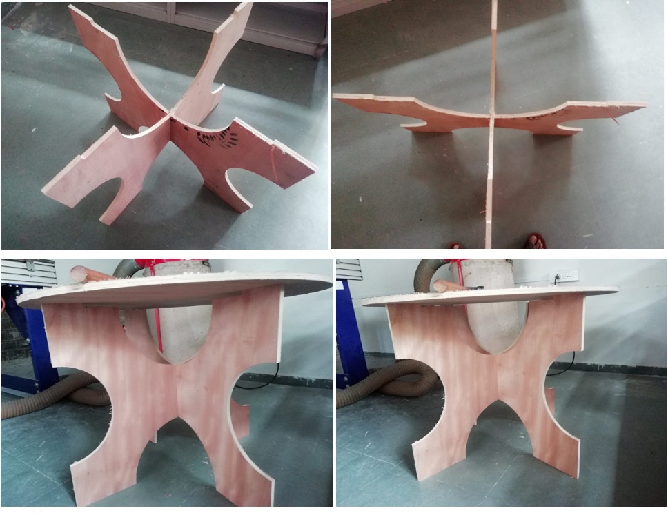
Now All parts are ready.
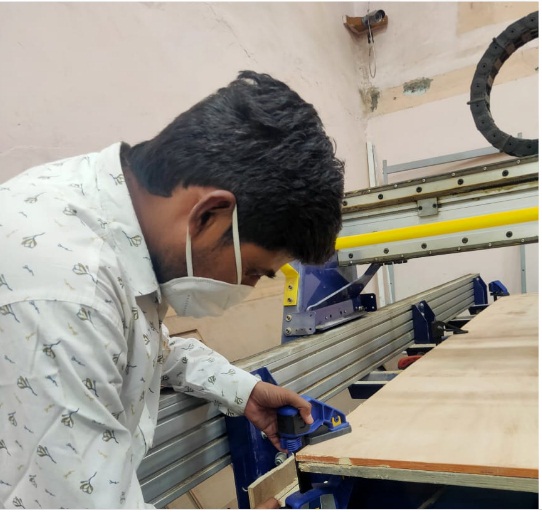
Assembling Parts
After finishing the cutting all parts I need to assembled this one by one so that it can be press fit properly and looks a perfects use full tea table.
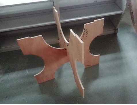
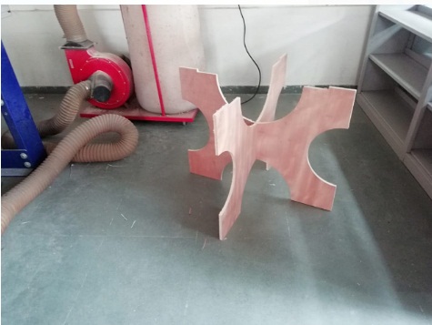
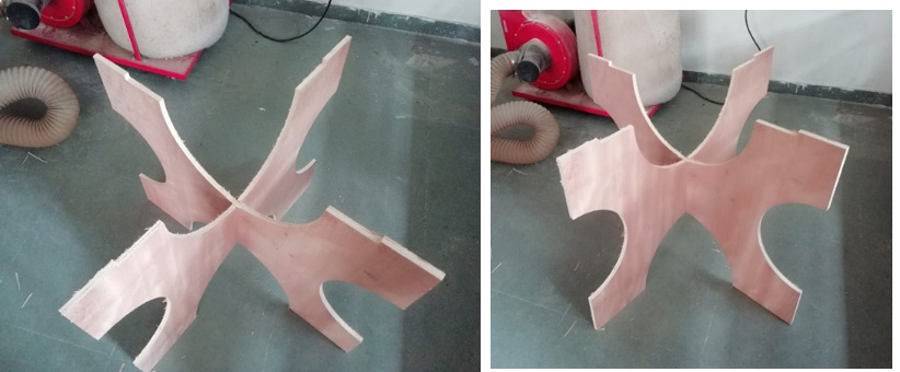
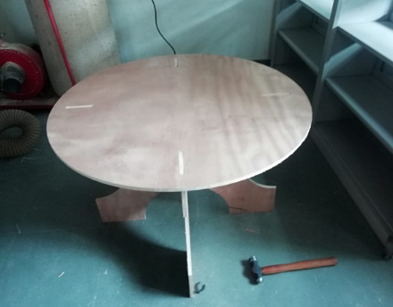
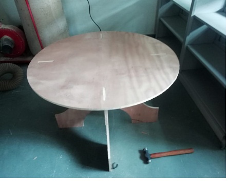
Now the table is ready to use.

About tolerance/margin Consider during Design.
As I mentioned while designing the object in this week of assignment Due to COVID-19 we didn't have the Lab Access for Finding the various Parameter of Shob-bot Machine.for this I have reffered the last year document of our vigyan Ashram Students because they have used same Shop bot machine for completing their assignment at COEP college Pune Fab-LAB.
So while designing I wanted to use 12mm Plywood sheet for making by object. I have designed the object in FreeCad software By cosidering the kerf (tolerance) of 1mm, and designed my object by cosidering the 1mm tolerence/margine.