Fabacademy 2021
Group Project: Embedded Programming

Different Architectures
For this week's group project, we tried to cover as many different boards and architectures that we could. The idea was to understand the workflow for using these difererent architectures. Here are the architectures that we explored:
- Arduino
- Espressif
- micro:bit
- Raspberry Pi
Arduino
Arduino is one of the most recognizable names within the maker community. It is an open source hardware as well as software that allows users to quickly produce prototypes and facilitate hardware and software prototyping for folks with a non-technical background. Due to the platform being completely open-source, there is a lot of people who produce projects and products based on the Arduino. There are many different types of Arduino boards and they can be programmed using the Arduino IDE easily. We used the following boards:
- Arduino UNO
- Arduino Mega
- Arduino Leonardo
Arduino UNO
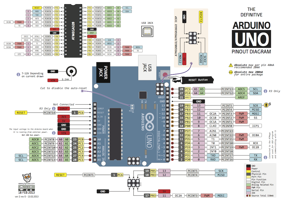
Arduino UNO is a very popular board of the Arduino family, and it allows users to get a feel for hardware prototyping in a compact but easy to use manner. That is why it is called Arduino UNO, as it is usually the first board that users get their hands on. Anyway, the UNO has the following technical specs:
- Name: Arduino UNO
- Microcontroller: Atmega328P-PU
- Operating Voltage: 5V
- Input Voltage: 7-20V
- Number of GPIO Pins: 20
- Digital Pins: 14
- PWM Pins: 6
- Analog Input Pins: 6
- I2C Ports: 1
- UART Ports: 1
- SPPI Ports: 1
- Flash Memory: 32 KB of which 0.5 KB used by bootloader
- SRAM: 2 KB
- EEPROM: 1 KB
- Clock Speed: 16 MHz
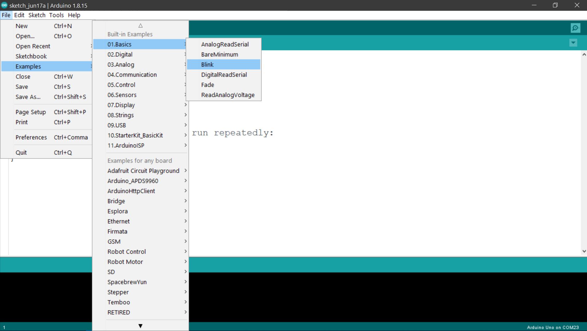
Using the UNO board is really simple when using the Arduino IDE. We tried to blink an LED with a simple sketch. Here are the steps that we followed to achieve this:
We took the example blink sketch from File>Examples>Basics>Blink
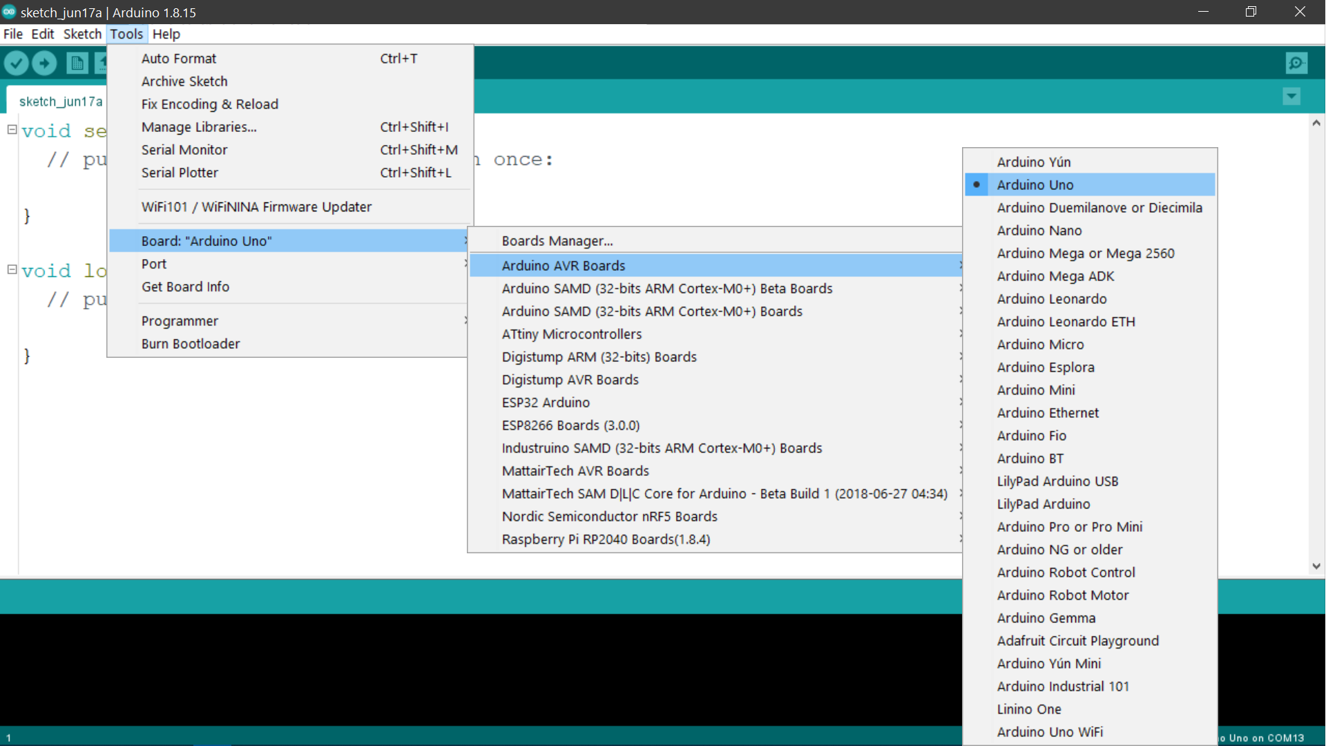
Before uploading the code to the Arduino, we checked Tools>Board>Arduino AVR Boards, to see if "Arduino/Genuino UNO is selected.
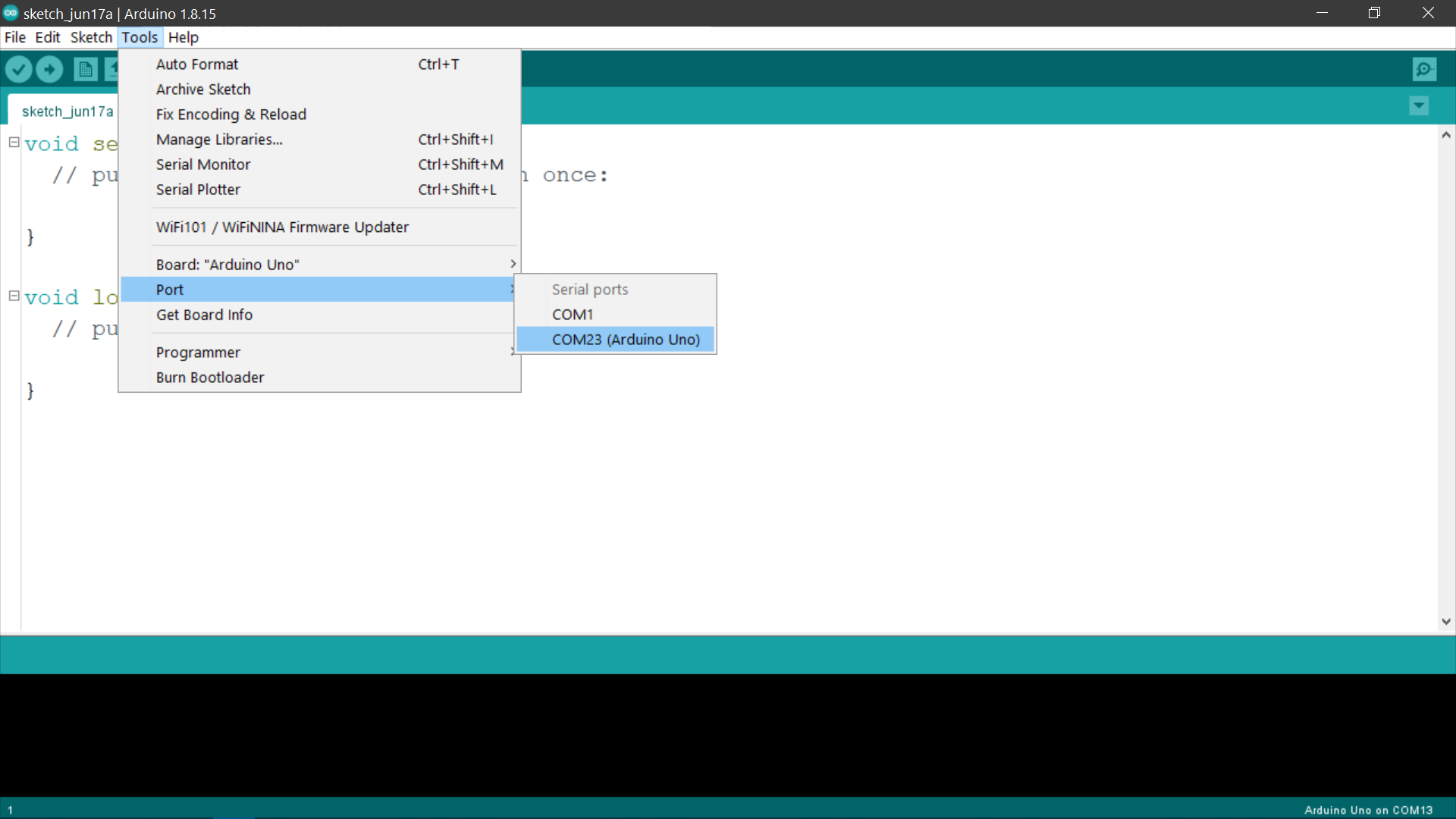
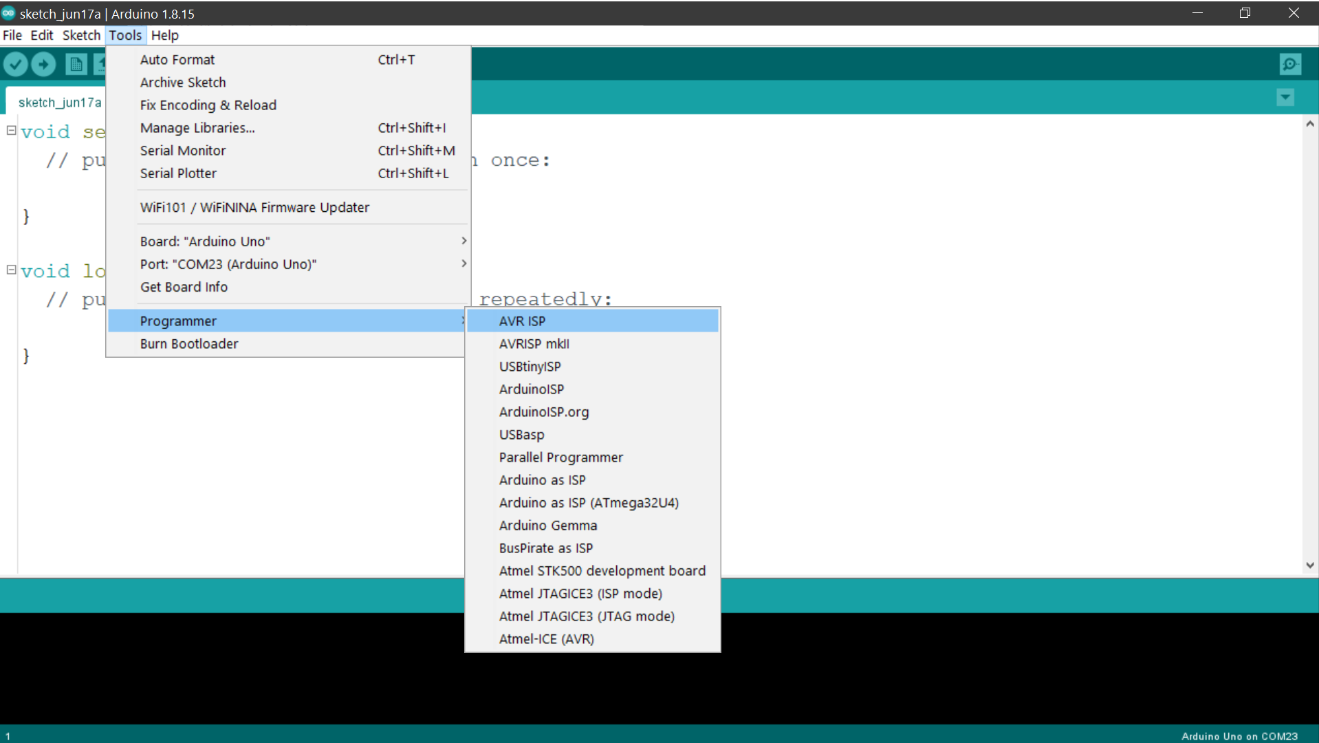
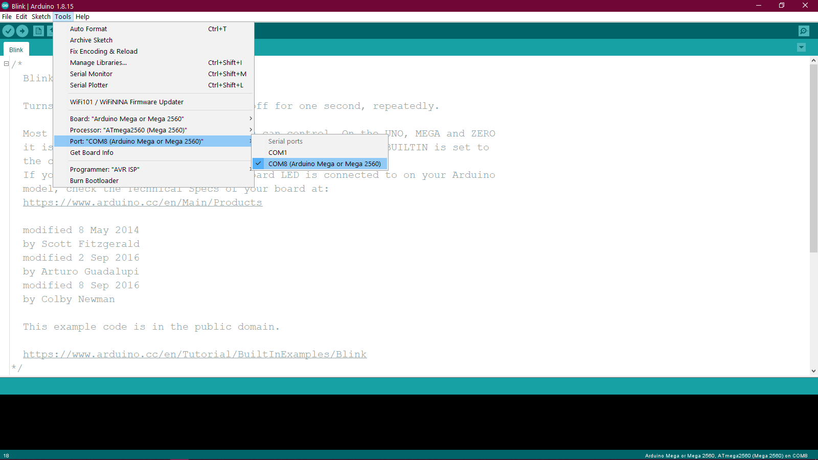
We also checked if the correct port was selected by checking the Tools>Port. As you can see in the picture below, the COM port of the Arduino has Arduino UNO written beside it in brackets.
This step is not absolutely essential but we checked to make sure that the AVRISP was selected under Tools>Programmer.
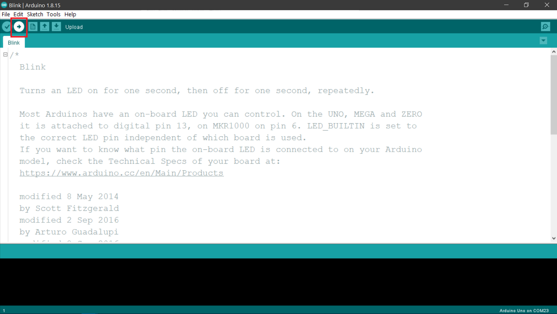
After all this, we uploaded the code to the board by clicking on the upload button as highlighted below.
After the code was done uploading, we saw the result of the program in the form of the blinking onboard LED.
Arduino Mega
Arduino UNO has a good amount of GPIO pins, but one might need more number of pins for a more complex project. Enter Arduino Mega. This board is a member of the Arduino family, with many more GPIOs and also a larger memory and static RAM. Here are the technical specs of this board:
- Name: Arduino Mega
- Microcontroller: Atmega2560
- Operating Voltage: 5V
- Input Voltage: 7-20V
- Number of GPIO Pins: 70
- Digital Pins: 54
- PWM Pins: 15
- Analog Input Pins: 16
- I2C Ports: 1
- UART Ports: 4
- SPPI Ports: 1
- Flash Memory: 256 KB of which 0.5 KB used by bootloader
- SRAM: 8 KB
- EEPROM: 4 KB
- Clock Speed: 16 MHz
Using the Arduino Mega is very similar to using the Arduino UNO in terms of the steps involved, the only difference is the board and ports will change for the board. Here are the steps nonetheless. We are still using the blink sketch to test the board:
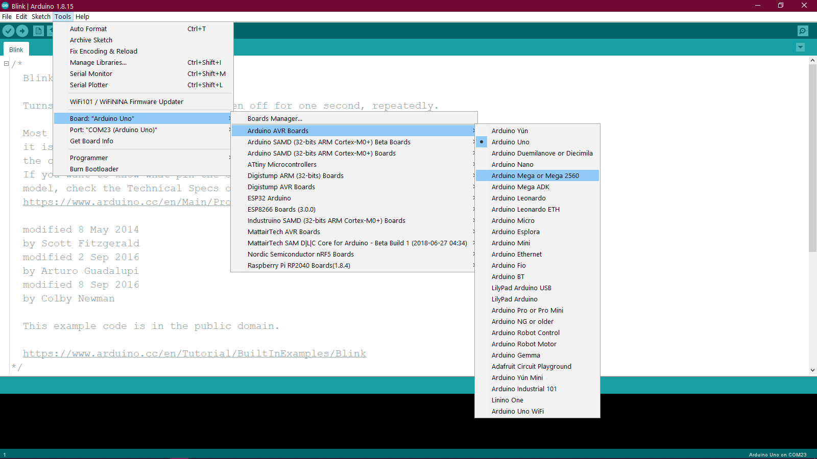
Since the blink program is already open, we directly went to Tools>Board>Arduino AVR Boards and selected the Arduino Mega or Mega 2560 option.
We then selected the correct COM port from the Tools>Port.
And then after uploading the code, this was the result:
Arduino Leonardo
The Arduino UNO and Mega are great for basic prototyping, but what does one do when they want to build a device that can act as a Human Interface Device or an HID. The Arduino Leonardo is designed with that purpose in mind. Here are the technical specs of the board:
- Name: Arduino Leonardo
- Microcontroller: Atmega32u4
- Operating Voltage: 5V
- Input Voltage: 7-20V
- Number of GPIO Pins: 20
- Digital Pins: 20
- PWM Pins: 7
- Analog Input Pins: 12
- I2C Ports: 1
- UART Ports: 4
- SPPI Ports: 1
- Flash Memory: 32 KB of which 0.5 KB used by bootloader
- SRAM: 2.5 KB
- EEPROM: 1 KB
- Clock Speed: 16 MHz
For testing this board, Mohit used the code that he was writing as a part of his final project to show the USB emulation functionality of the Leonardo. Here's what he did:
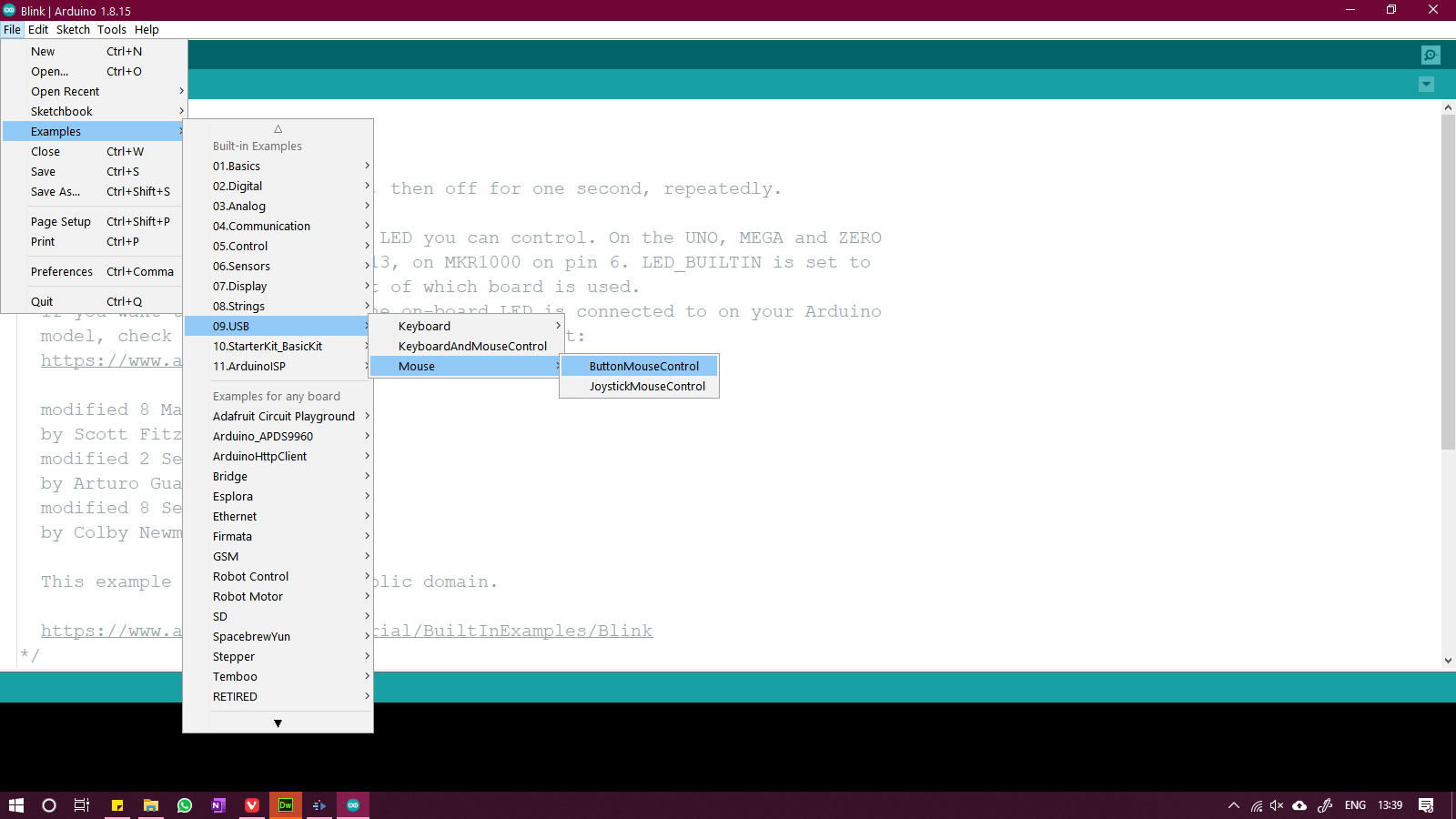
He took the USB mouse example from the USB>Mouse>ButtonMouseControl
He modified the code to make his own code which is linked below:
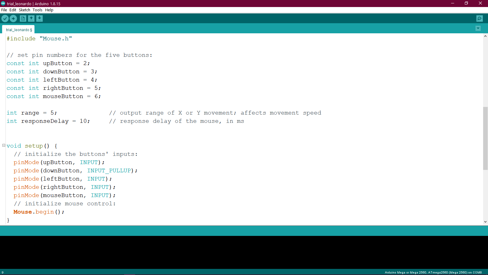
Code for the Leonardo Board
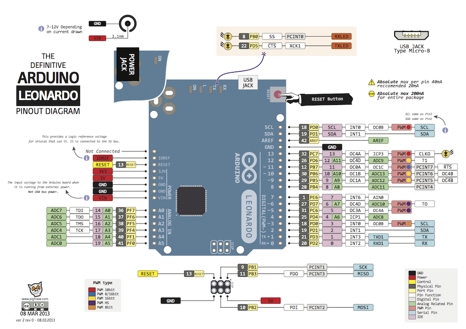
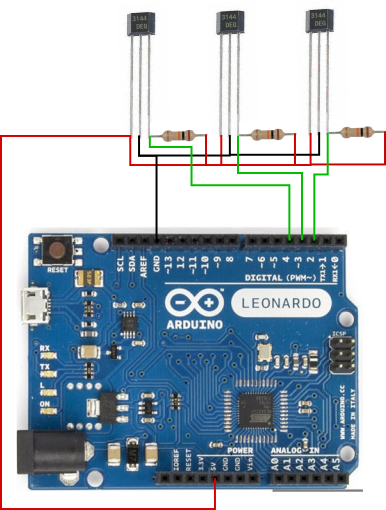
He connected the board to Hall effect sensors on pins 2, 3 and 4 using the following diagram:
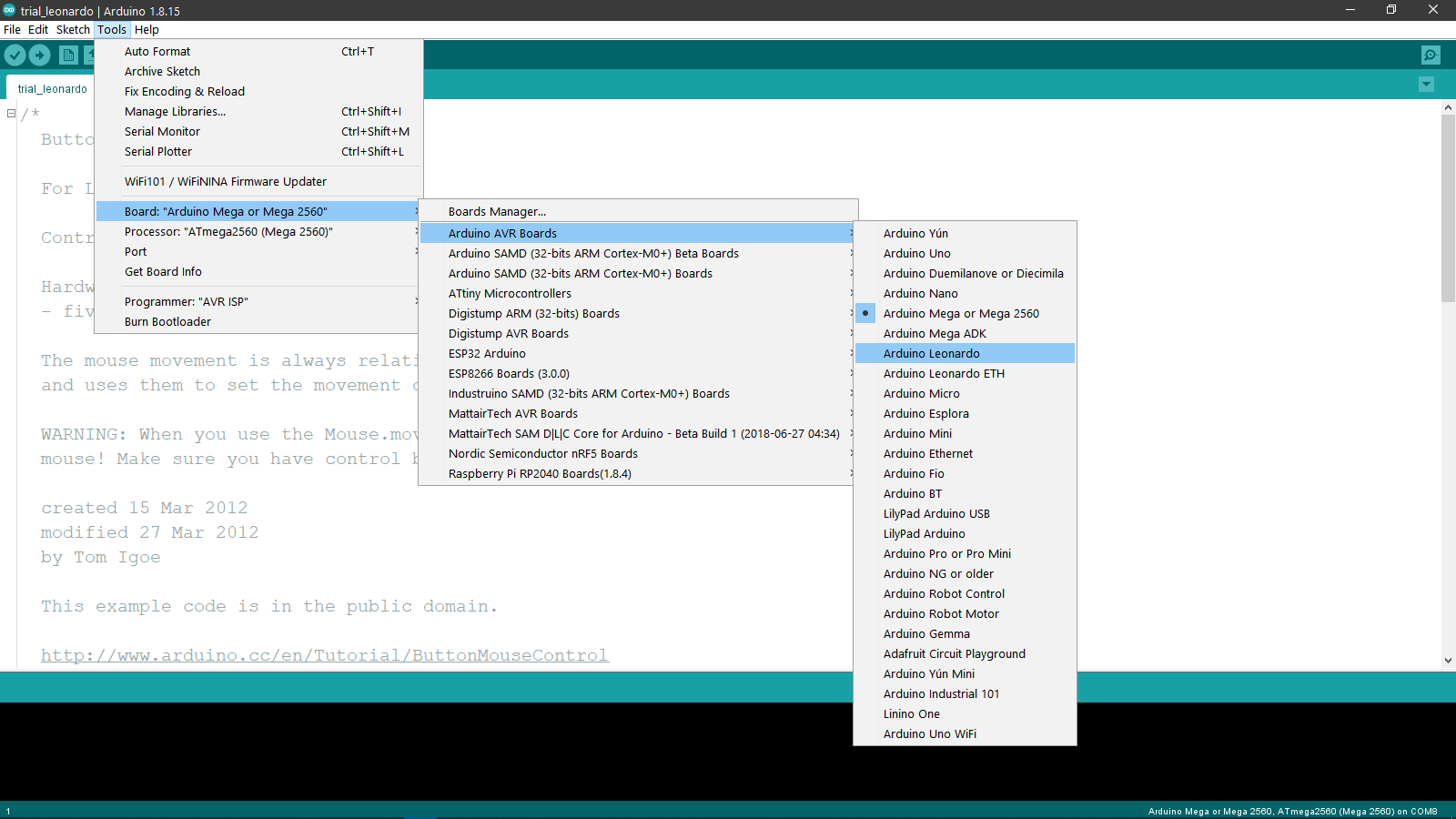
Then to upload the code, we selected the Arduino Leonardo from the Tools>Board>Arduino AVR Boards
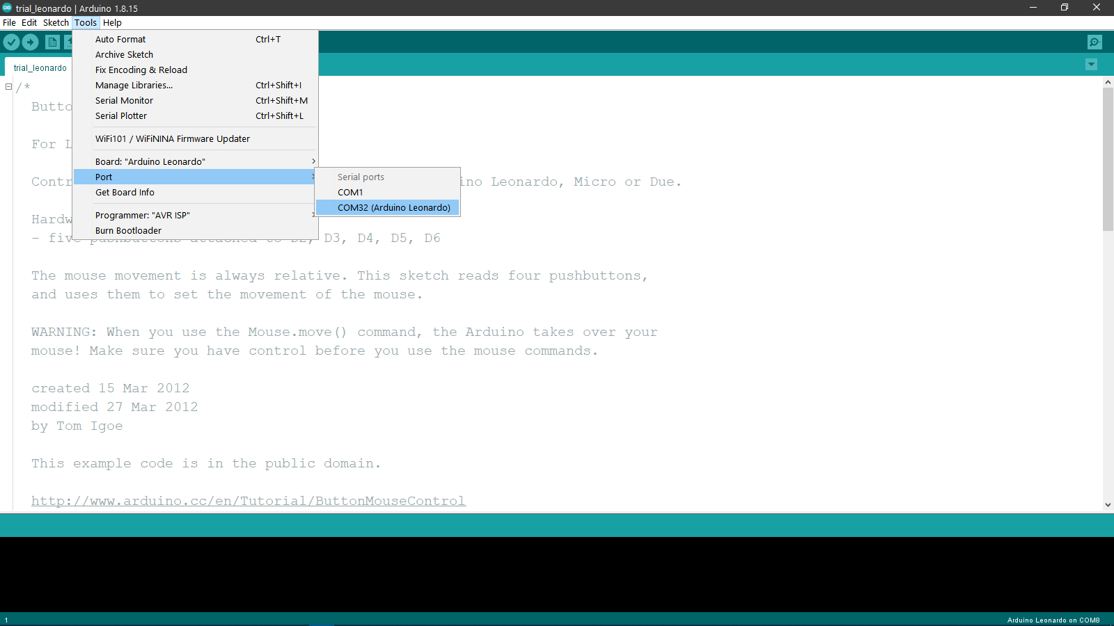
And we also selected the correct COM port from the Tools>Port.
And after uploading the code, you can see the demonstration of the code in the video below:
Digispark
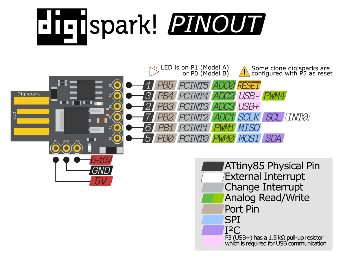
The Arduino UNO, Mega and Leonardo are good for prototyping, but when the project doesn't need a lot of pins or memory space, then we can go for some smaller sized microcontrollers. The Digispark attiny85 module is one such board. Here are the technical specs of the board:
- Name: Digispark
- Microcontroller: Attiny85
- Operating Voltage: 5V
- Input Voltage: 6-16V
- Number of GPIO Pins: 6
- Digital Pins: 6
- PWM Pins: 3
- Analog Input Pins: 4
- I2C Ports: 1
- UART Ports: 1
- SPPI Ports: 1
- Flash Memory: 8 KB of which 2 KB used by bootloader
- SRAM: 512 B
- EEPROM: 512 B
- Clock Speed: 1 MHz Internal Oscillator
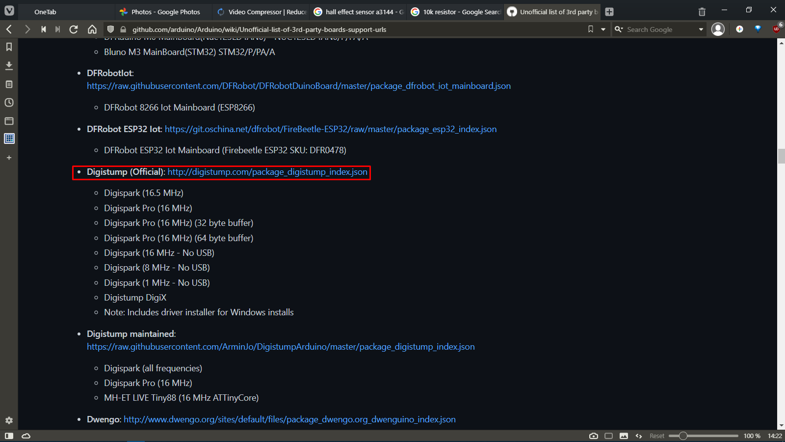
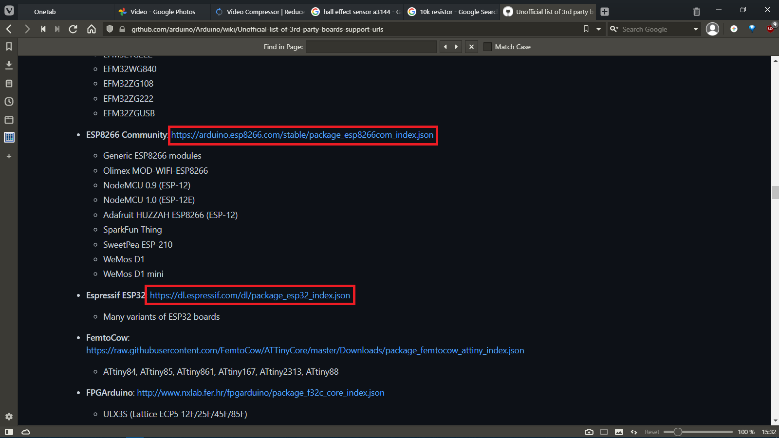
Since the Digispark board is not a default board for the Arduino IDE, its support needs to be added to the IDE by going to the Unofficial list of 3rd party boards support urls page and selecting the appropriate link for the board as shown below:
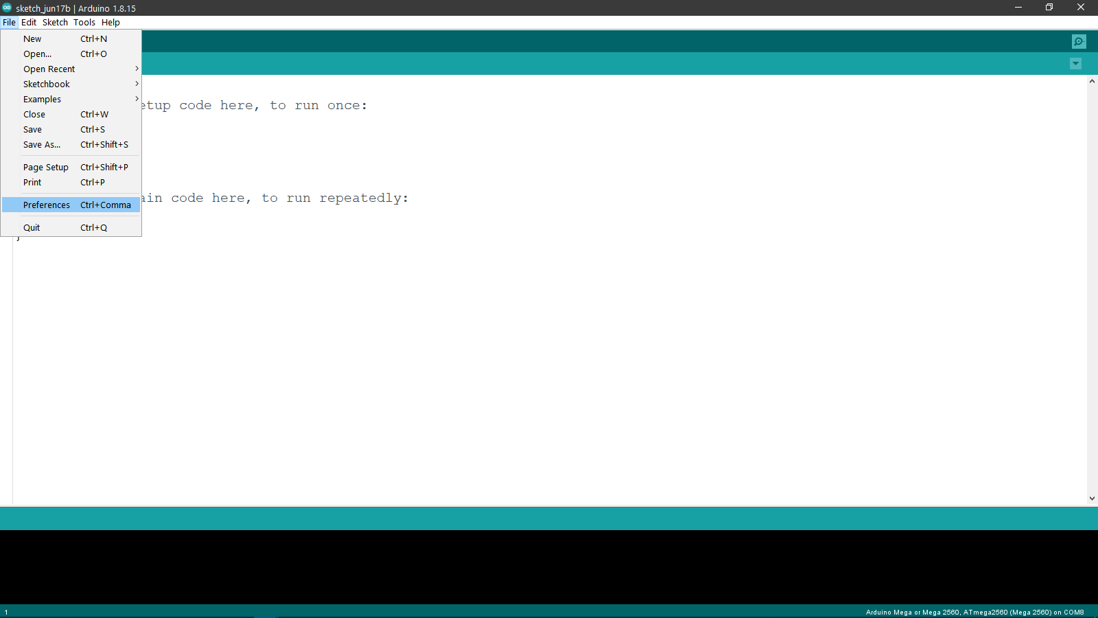
After copying the link from here, we went to the Arduino IDE and selected the File>Preferences option.
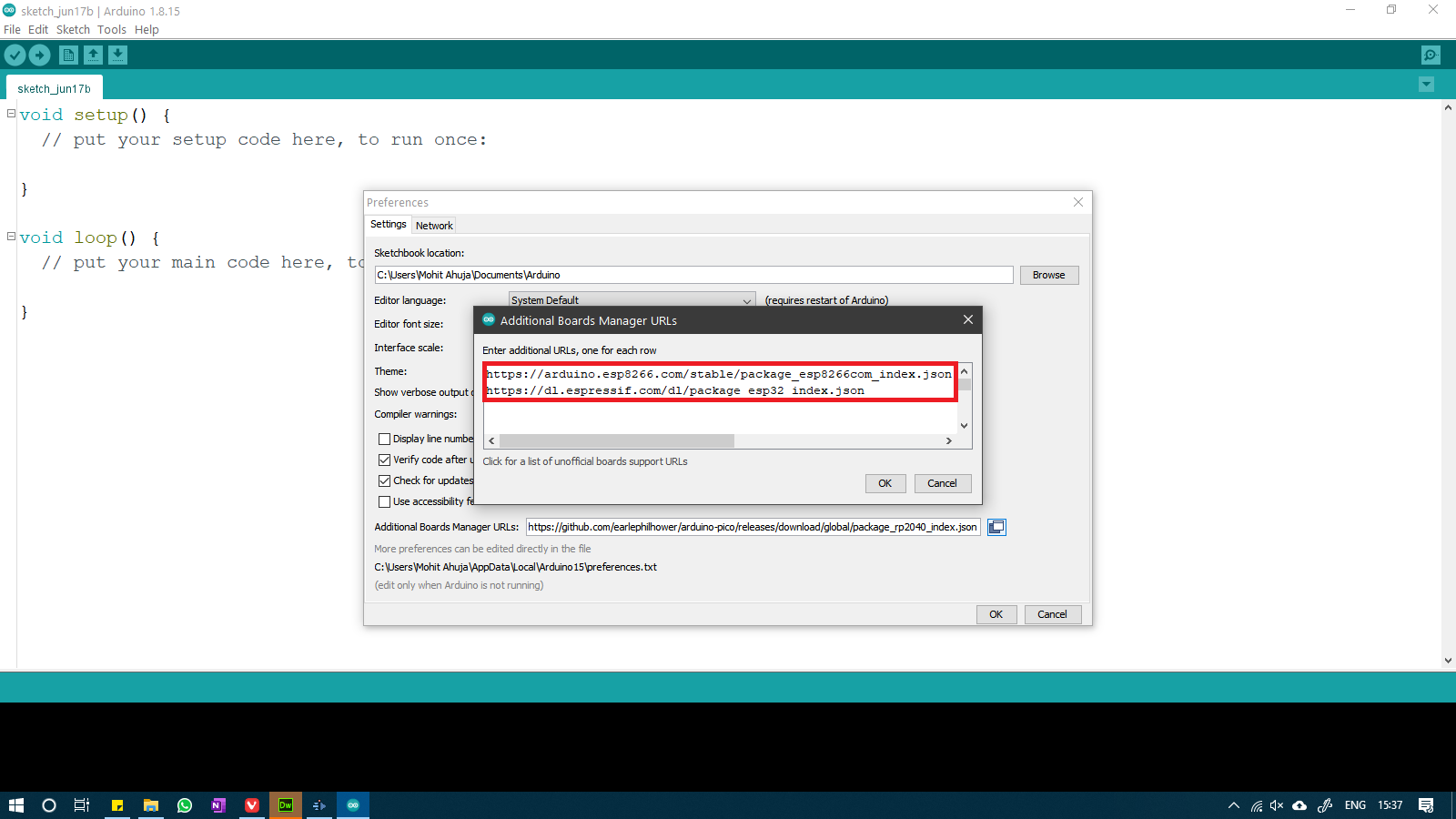
In the preferences window, we select the Additional Board Manager URLs and click on the buttton beside the bar as shown below:
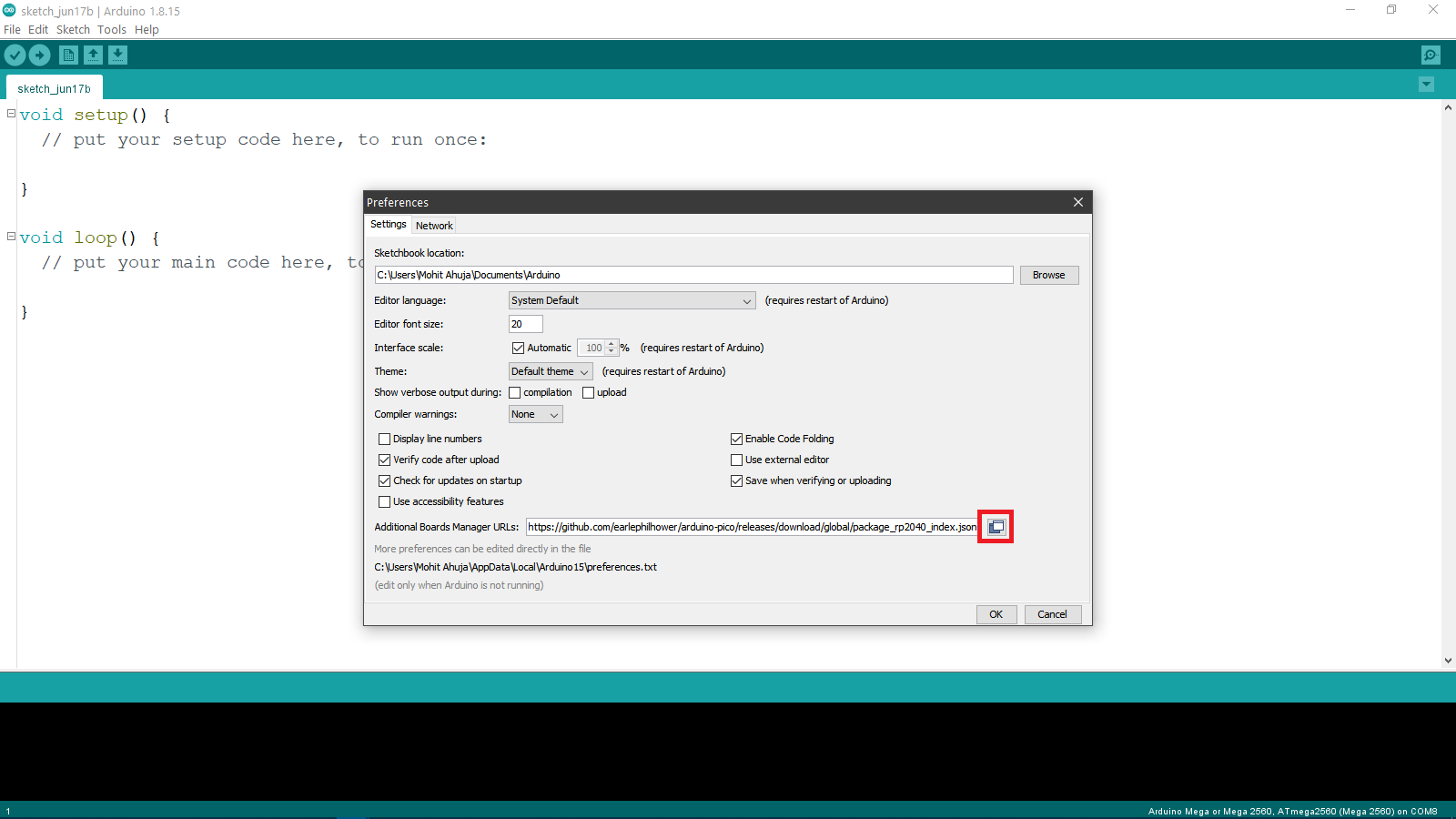
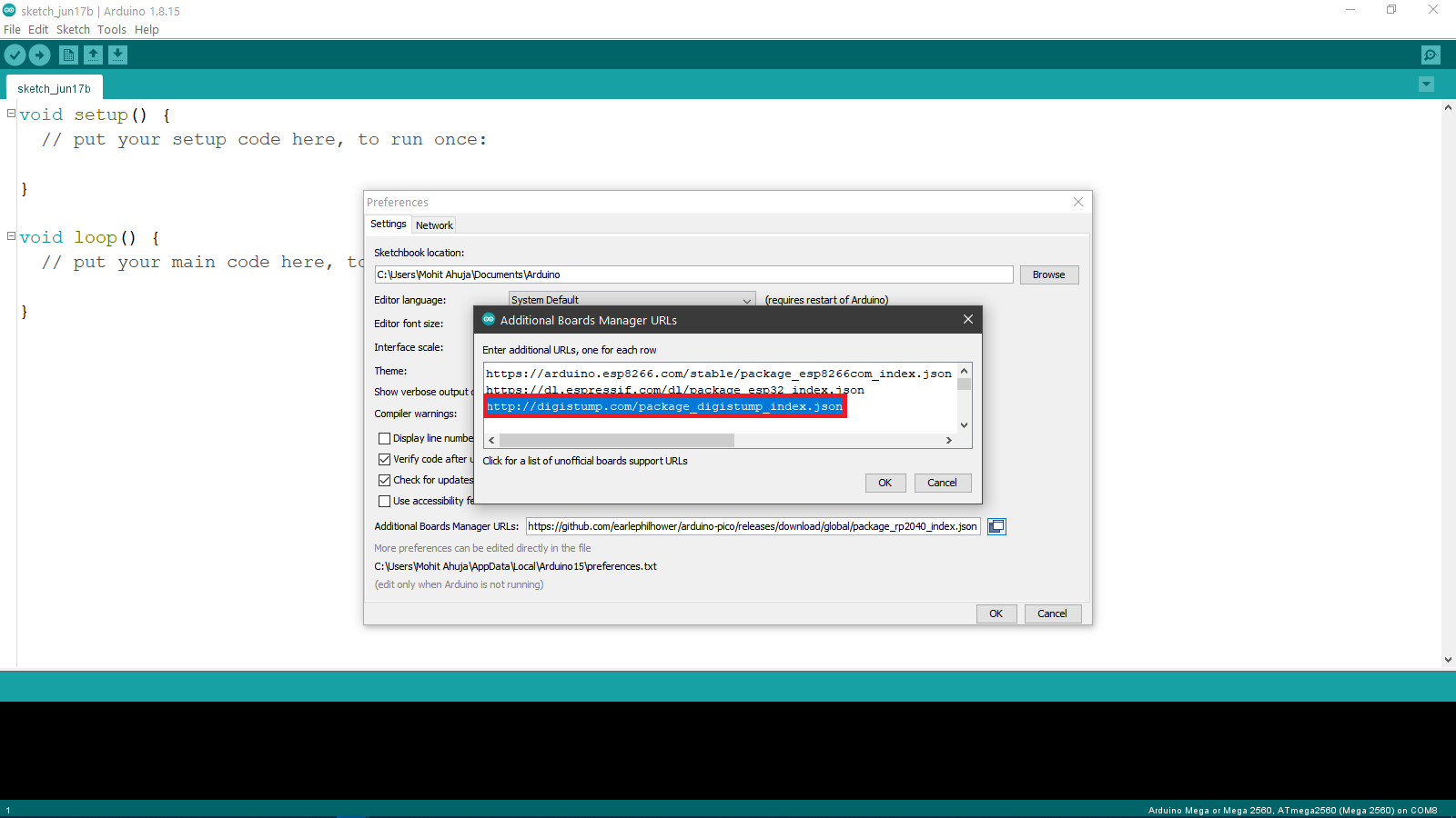
In the new window, we pasted the copied link from the website, and then clicked on ok.
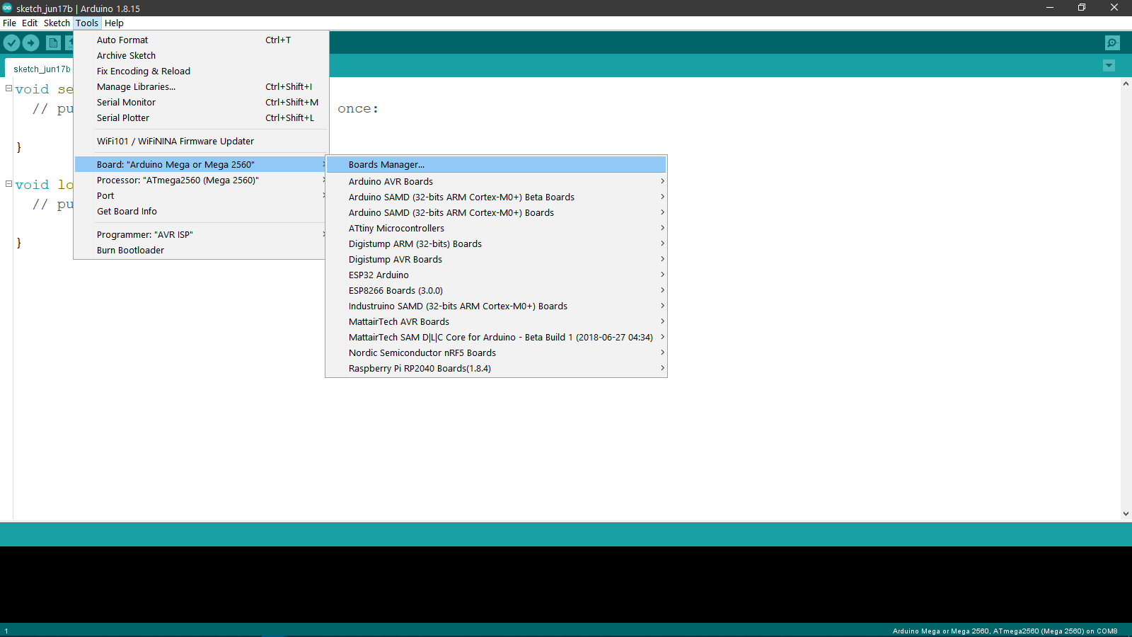
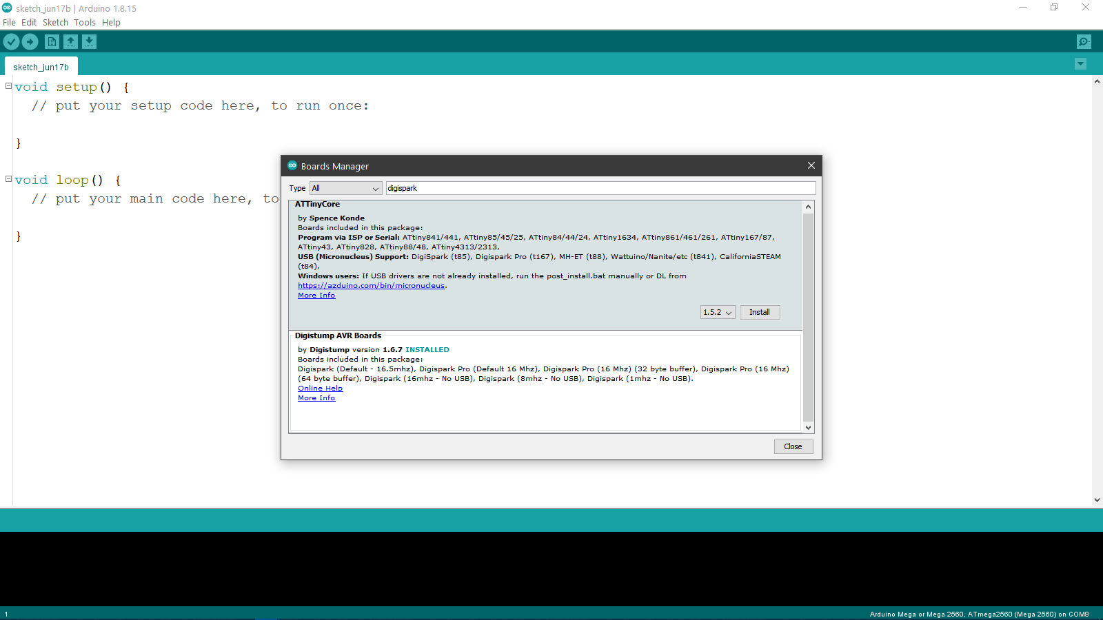
After that, we went to Tools>Board>Boards Manager and then we searched for "digispark" and then installed it by clicking on the install button:
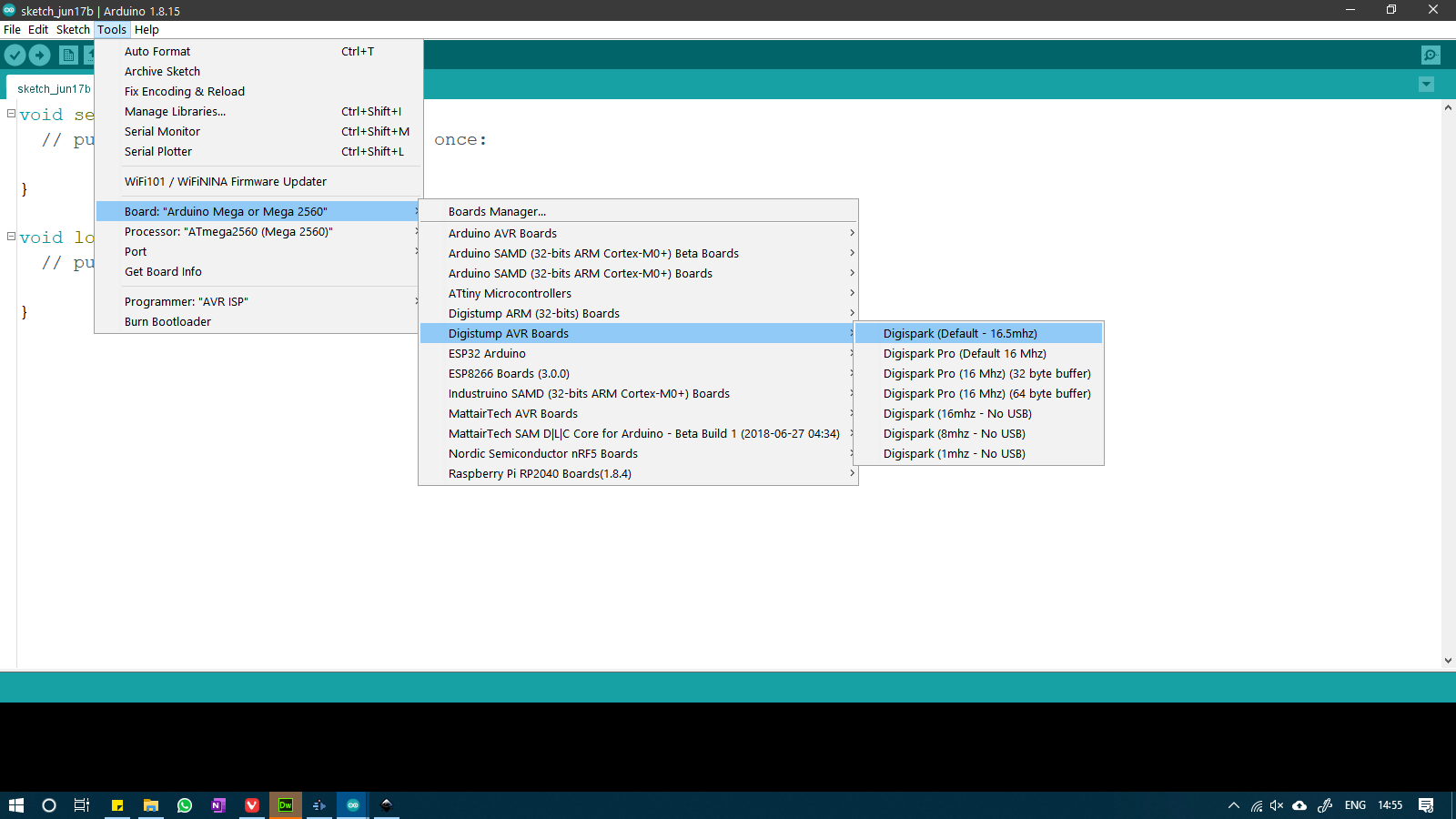
After installing the support for the boards, we selected the Digispark (Default 16.5MHz) board from the Tools>Board>Digistump AVR Boards
For testing the board, we modified the existing blink example by changing the pin number from LED_BUILTIN to pin 1 for the Digispark module. The modified code is attached below:
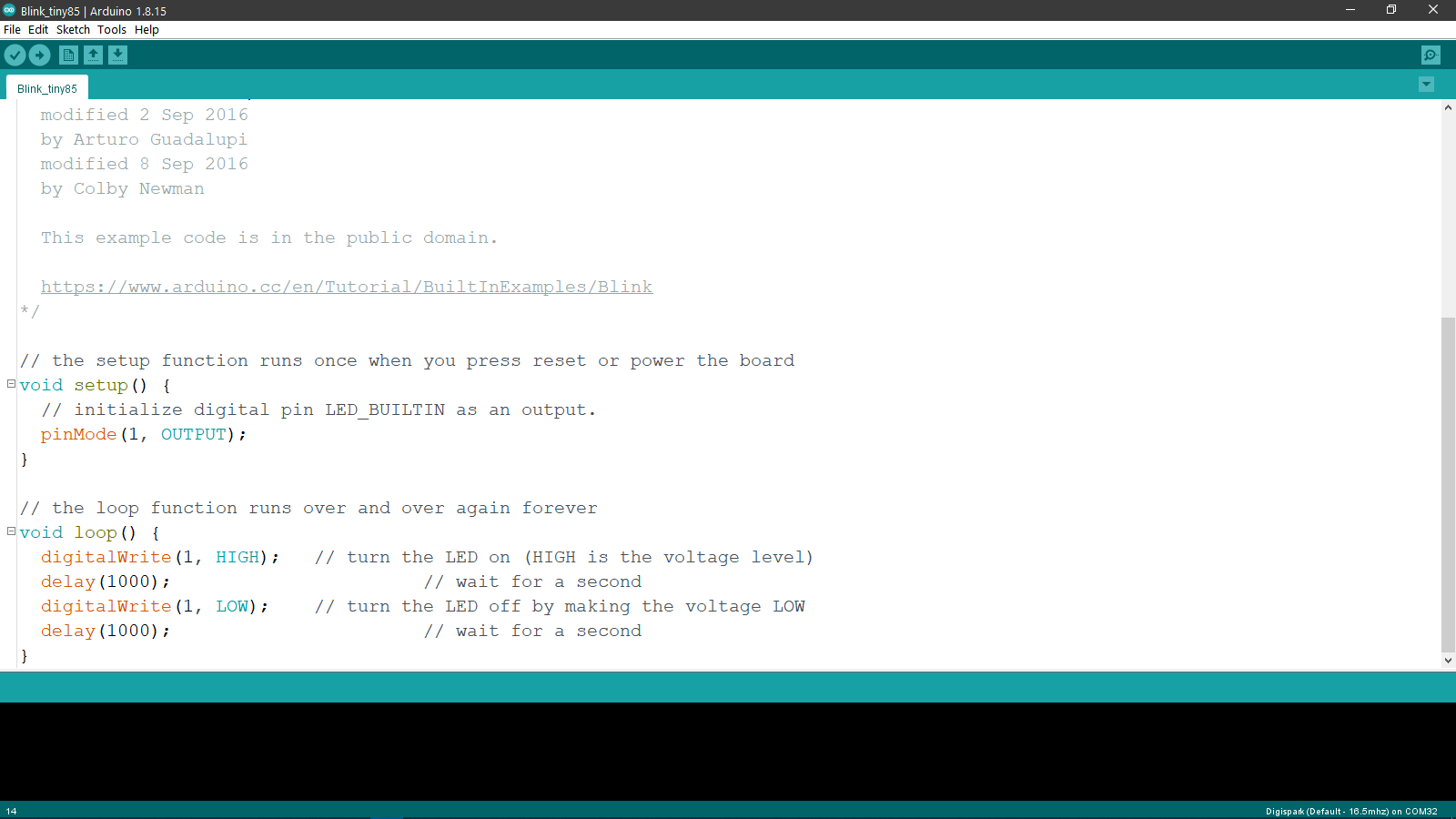
Code for the Digispark Module
So for uploading a program to this module, you actually need to connect it to the computer after the IDE begins the uploading process. It gives you a 60 second window within which you have to connect the board after which you will have to retry if the code does not get uploaded.
The reason for this is the Micronucleus bootloader on the board which enables the attiny85 to emulate usb and accept code through its GPIO pins. The Digispark module stays in programmable mode for 5 seconds after being plugged in. After that, it starts using the pins for Serial communication as normal GPIO pins.
So after the IDE printed the message in the bottom saying that the module needs to be plugged in, we plugged in the module and the modified blink sketch was uploaded.
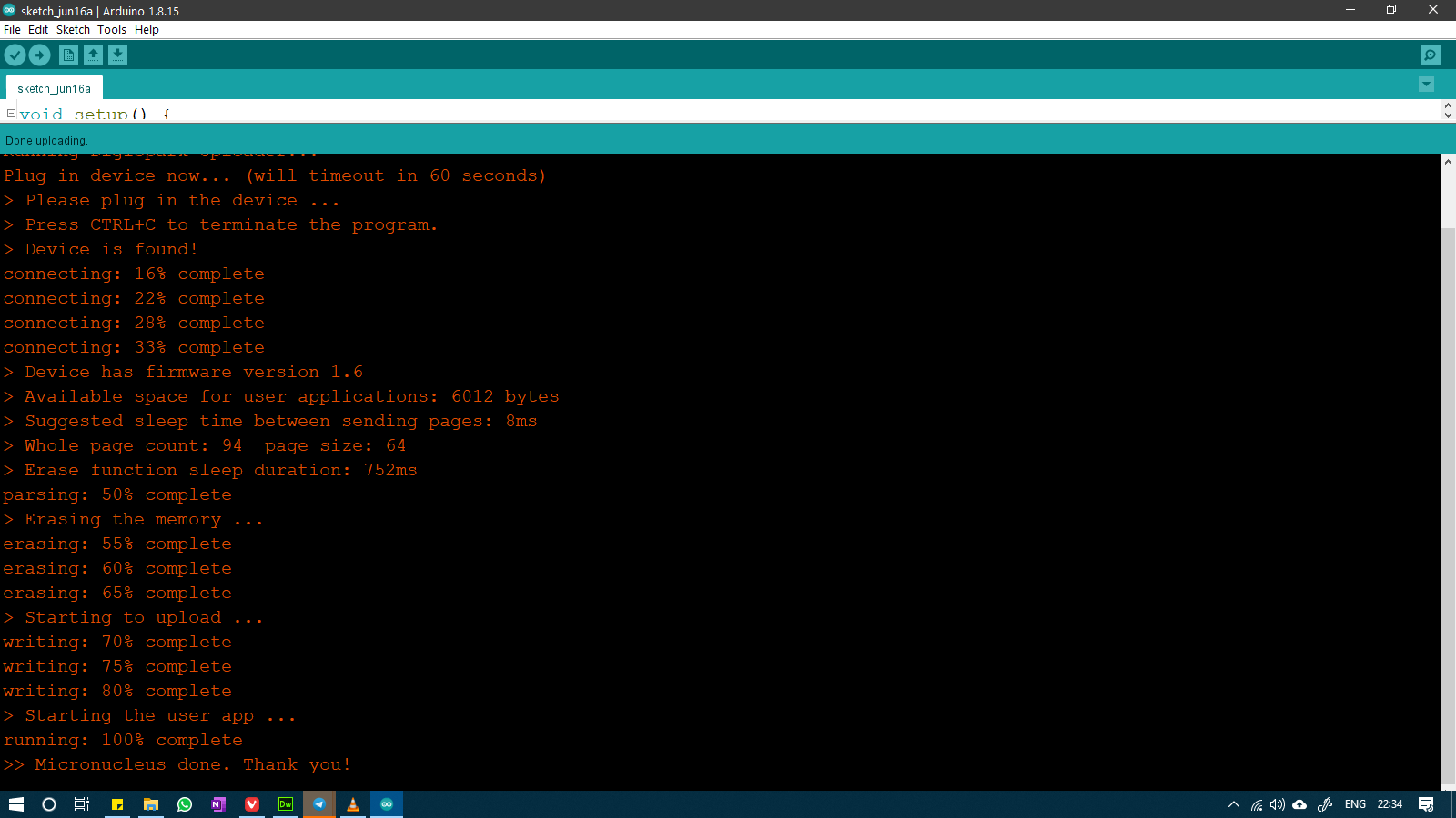
The modified blink program produced the following result:
Espressif
This is a family of commercially available and easily interfaceable MCUs which have onboard Wifi (and BLE for some chips). These are great for applications such as IoT and Wireless communication.
ESP8266
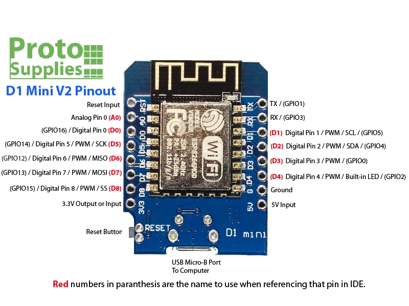
The ESP8266 is an MCU with integrated Wifi on board and it is a great choice for applications with IoT. We are using the WeMos D1 Mini Model of the board and it is a very easy module to interface with the Arduino IDE.
- Name: D1 Mini
- Microcontroller: ESP8266MOD
- Operating Voltage: 3.3V
- Input Voltage: 5-24V
- Number of GPIO Pins: 11
- Digital Pins: 11
- PWM Pins: 4
- Analog Input Pins: 1
- I2C Ports: 1
- UART Ports: 1
- SPPI Ports: 1
- Flash Memory: 4MB
- SRAM: <36kB bytes
- Clock Speed: 80/160 MHz
To use this board, we need to add the support for this IC as well by going to the Unofficial 3rd party boards support urls page and choosing the link for esp8266. We copied the links for both esp8266 as well as esp32.
And then we did the same steps as the digispark module for adding the links to the Additional Board Manager URLs section.
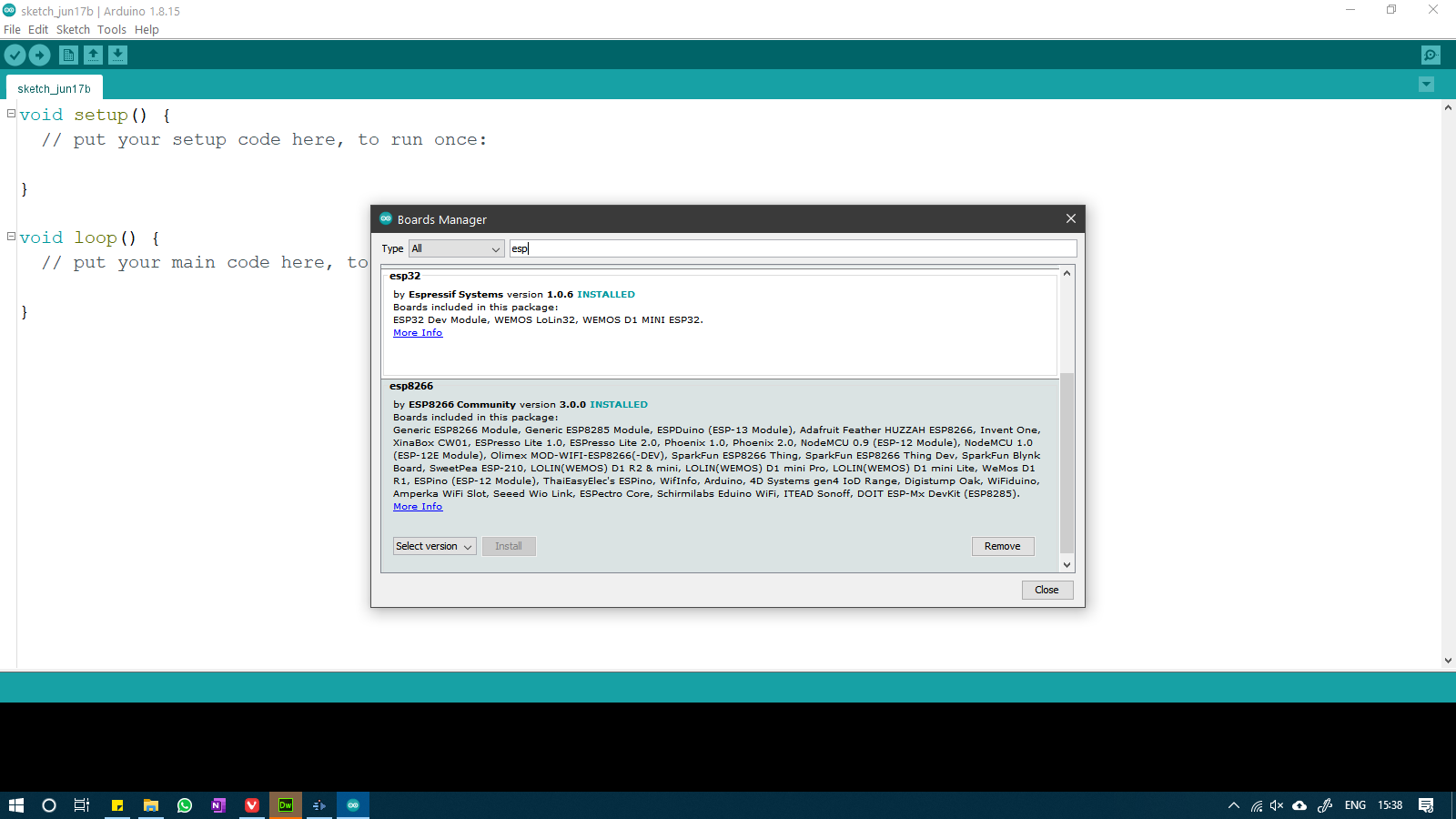
After this, we installed the board definitions for esp8266 as well as esp32 from the Board Manager window by searching "esp" and then clicking on install
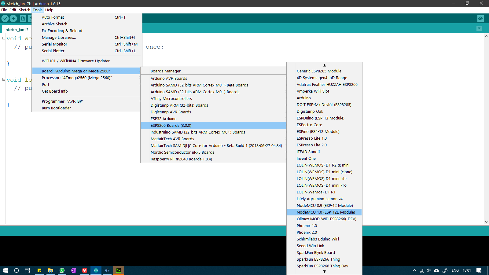
After installing the board definitions, we will use the ESP8266 for uploading code to our board. To use it, we went to Tools>Board>ESP8266 boards
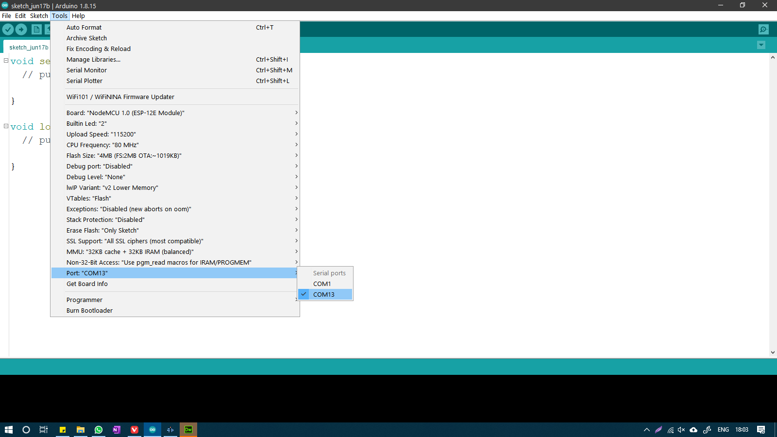
After that we selected the COM port from Tools>Port>
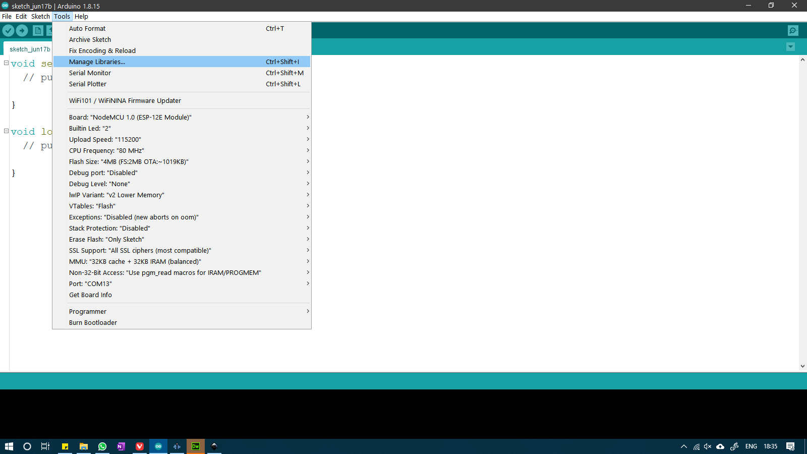
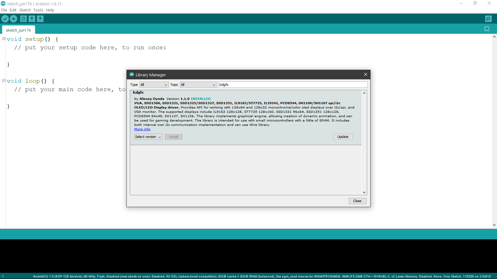
For testing this board, we used the lcdgfx library to run a demo animation on an SSD1306 I2C OLED LCD Screen. We downloaded the library from Tools>Manage Libraries and then searched for lcdgfx.
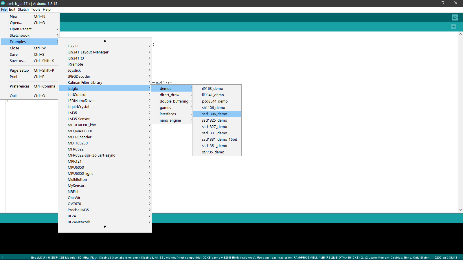
After installing the library, we went to File>Examples>lcdgfx>demos>ssd1306_demo.
We modified the code to fit the ESP8266, which can be found below:
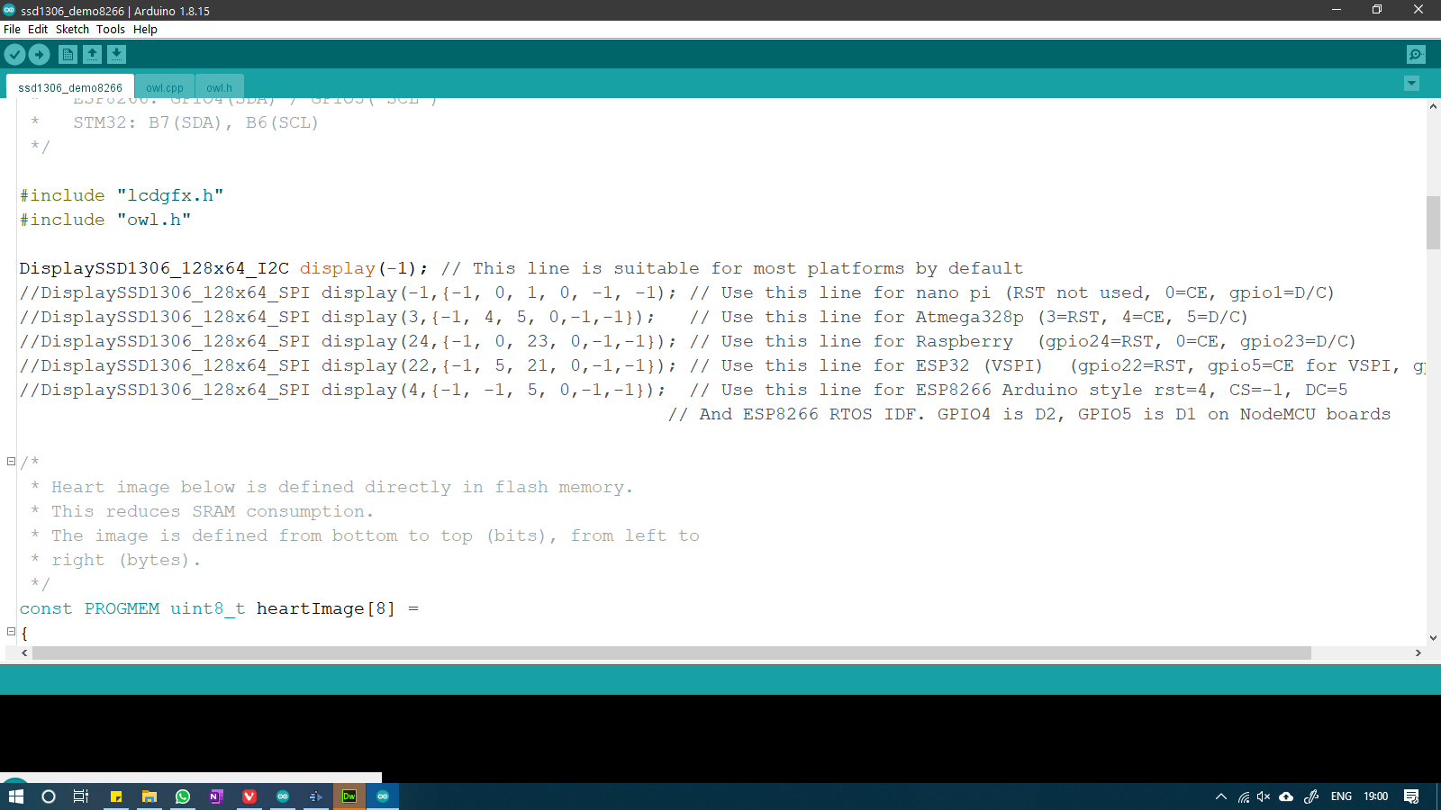 Code for the OLED LCD and ESP8266
Then I made the appropriate connections between the OLED and the ESP8266 according to the diagram shown below:
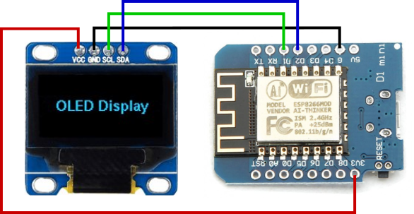
And this was the result of the uploaded code:
ESP32
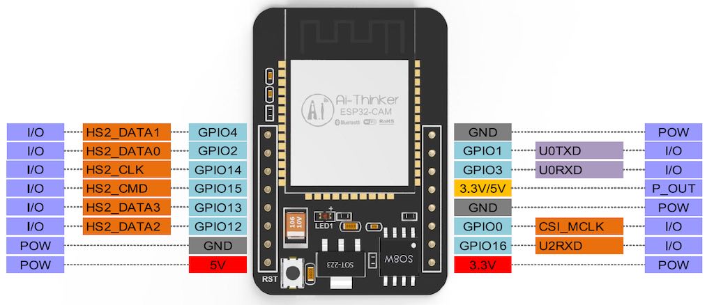
We used the ESP-CAM, which is a variation of the ESP-32 with a camera attached to the board as well as a microSD card slot that would be useful for storing the images/video captured by the camera. The ESP-32 is a chip that integrates a Wifi as well as a Bluetooth Low Energy Device in a single package. Here are the technical specs of the board:
- Name: ESP-CAM
- Microcontroller: ESP32-S
- Operating Voltage: 3.3V
- Input Voltage: 5-24V
- Number of GPIO Pins: 9
- Digital Pins: 9
- PWM Pins: 4
- Analog Input Pins: 1
- I2C Ports: 1
- UART Ports: 1
- SPPI Ports: 1
- Flash Memory: 4MB
- SRAM: 520kB bytes
- PSRAM: 4MB
- Clock Speed: 160 MHz
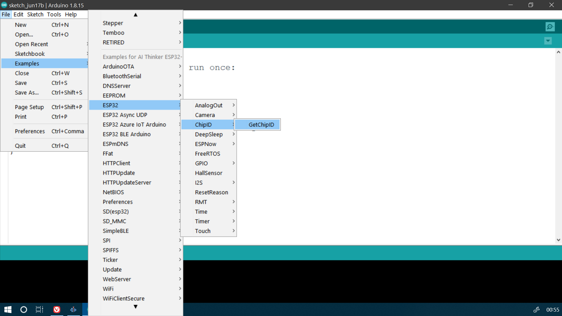
To show that the ESP-CAM is operational, we went with the Examples>ESP32>ChipID>GetChipID example.
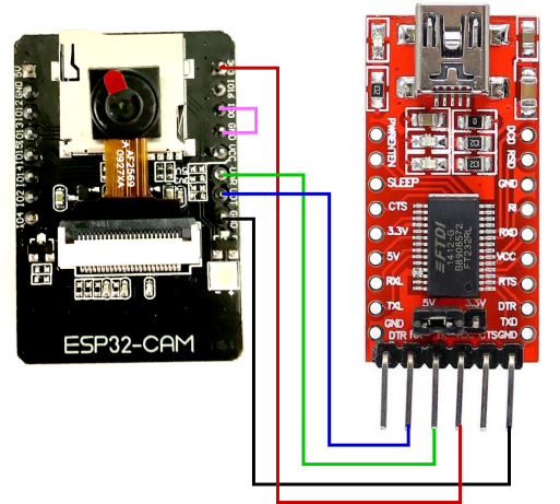
To upload the code to the board, we need to connect the board to the computer via a USB to TTL converter, and to do that, we will be using an FTDI breakout board set to 3.3V on the power jumper. Some say that it doesn't matter, but it is better to be safe and use the voltage at which the board operates, which is 3.3V. We followed the schematic below to connect the FTDI breakout board to the ESP-CAM module.
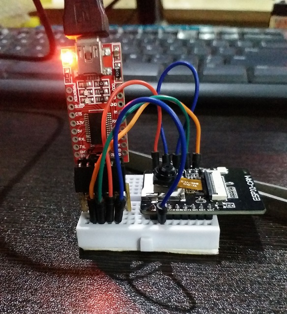
This is what it looks like after making the aforementioned connections:
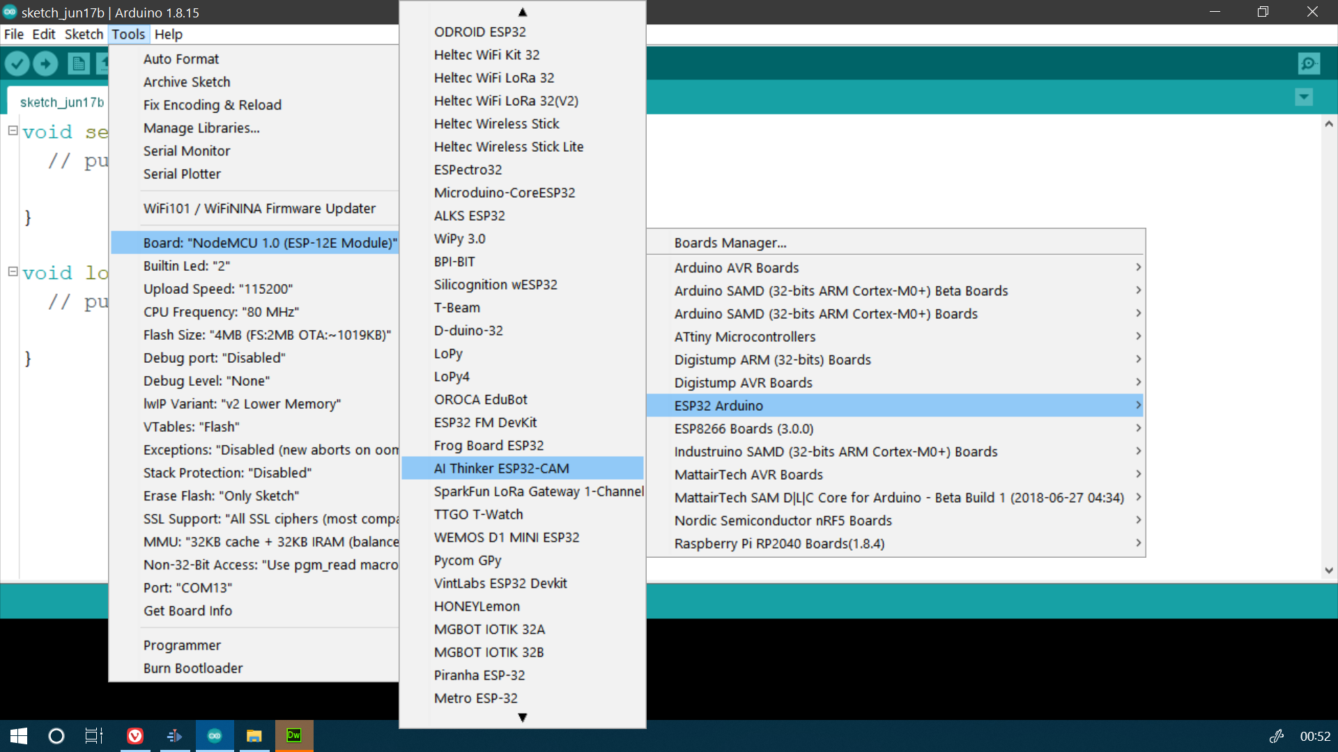
On the software side of things, we chose the board by going to Tools>Board>ESP32 Arduino>AI Thinker ESP32-CAM
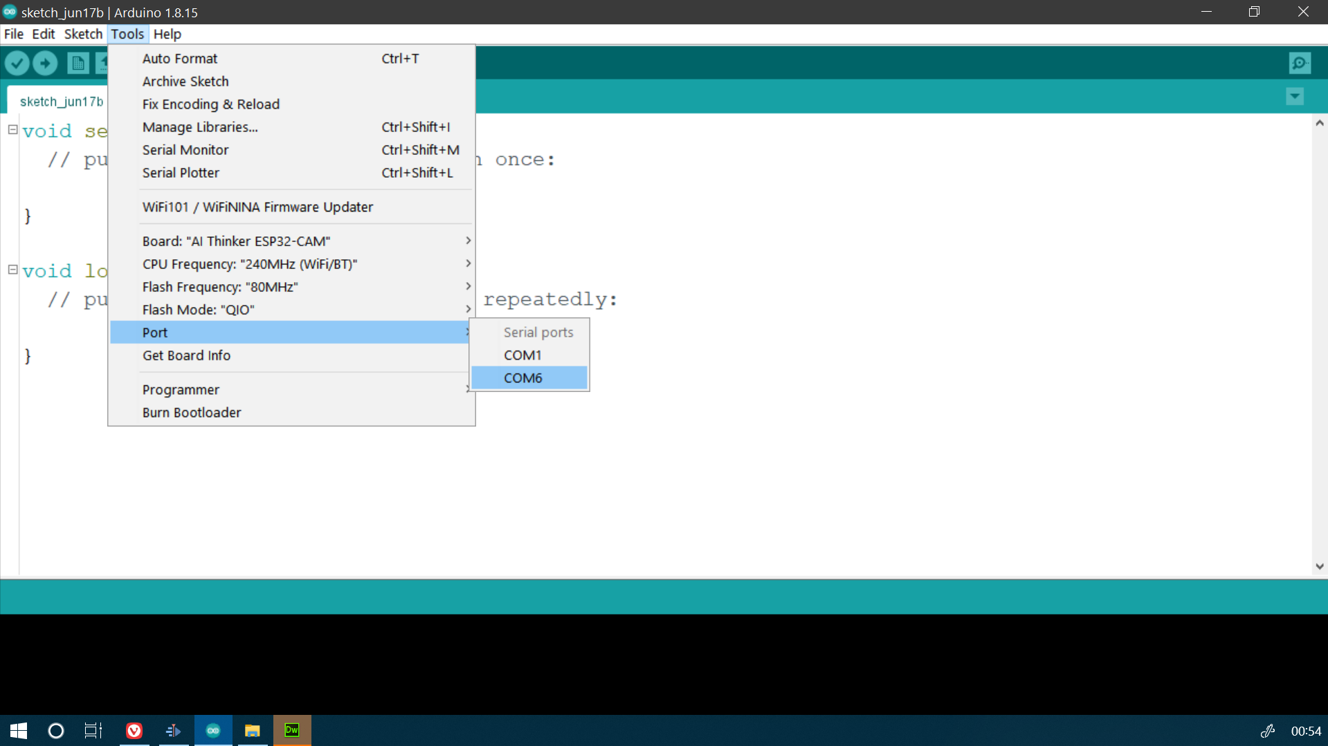
After that we chose the port by going to Tools>Port
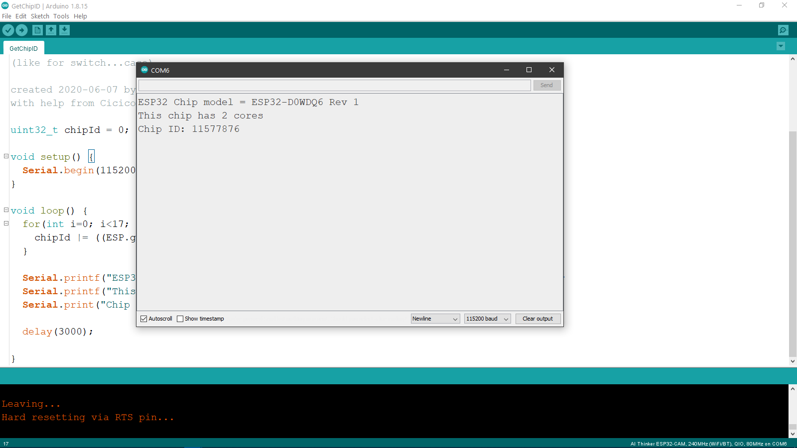
And after uploading the code, this was the output on the Serial Monitor:
We also tried flashing the flash LED using the blink program, which we modified because on the ESP32-CAM, the Flash LED is connected to GPIO 4. The modified code is linked below:
Code for flashing ESP32-CAM LED
Here is the result of the program, and as you can see in the video, it was too bright for the camera:
One thing that is worth mentioning is that in order to take the board out of programming mode and into the sketch running mode, we need to disconnect the jumper between IO0 and ground after the code is uploaded. Usually it is achieved by a button of some sort on the board, but we need to do this manually here.
micro:bit
micro:bit is a microcontroller board made by the BBC and maintained by Microsoft. It was designed as a tool to teach students about programming in an easy and fun to learn manner. Since it was introduced, it has been adopted very successfully across the world in school and college curriculums and makerspaces, and is especially popular with kids. The board incorporates a lot of peripherals apart from the microcontroller itself, such as a rf radio module, an accelerometer,a magnetometer compass, a microphone, a buzzer, 5x matrix LEDS and it also allows you to connect upto 3 GPIO pins with external components. And if you use an Edge connector for the microbit, you can get up to 19 GPIO pins from the microcontroller. Here is the link to the website with more information about the pins. We will be using the latest version of the micro:bit.
- Name: micro:bit
- Microcontroller:nRF52833
- Operating Voltage: 3.3V
- Input Voltage: 4.5-5.25V
- Number of GPIO Pins: 3/19
- Digital Pins: 19
- PWM Pins: 19
- Analog Input Pins: 6
- I2C Ports: 1
- UART Ports: 1
- SPPI Ports: 1
- Flash Memory: 256 KB
- SRAM:
- Clock Speed: 16 MHz
micro:bit has a different interface as compared to the Arduino and its relatives. It actually shows up as a memory device on the microcontroller and we paste the hex files of the programs that we made into the drive to upload it to the microcontroller's memory.
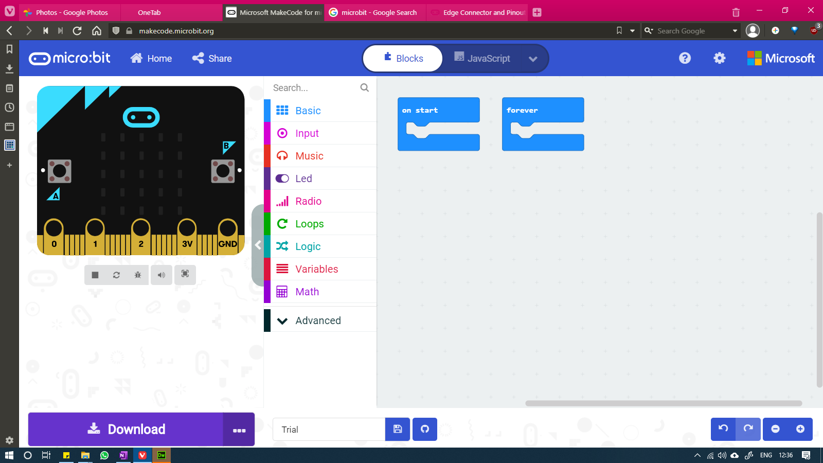
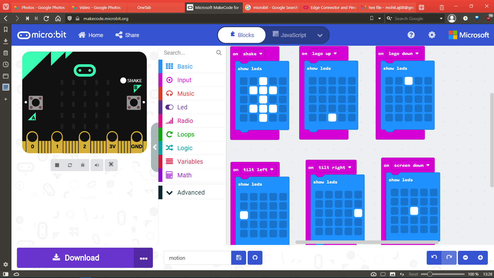
To make the code for the micro:bit, we use the website makecode.microbit.org, where you can write the program using the block based programming language or by using Javascript. To start a new code, we clicked on "New Project" as seen below:
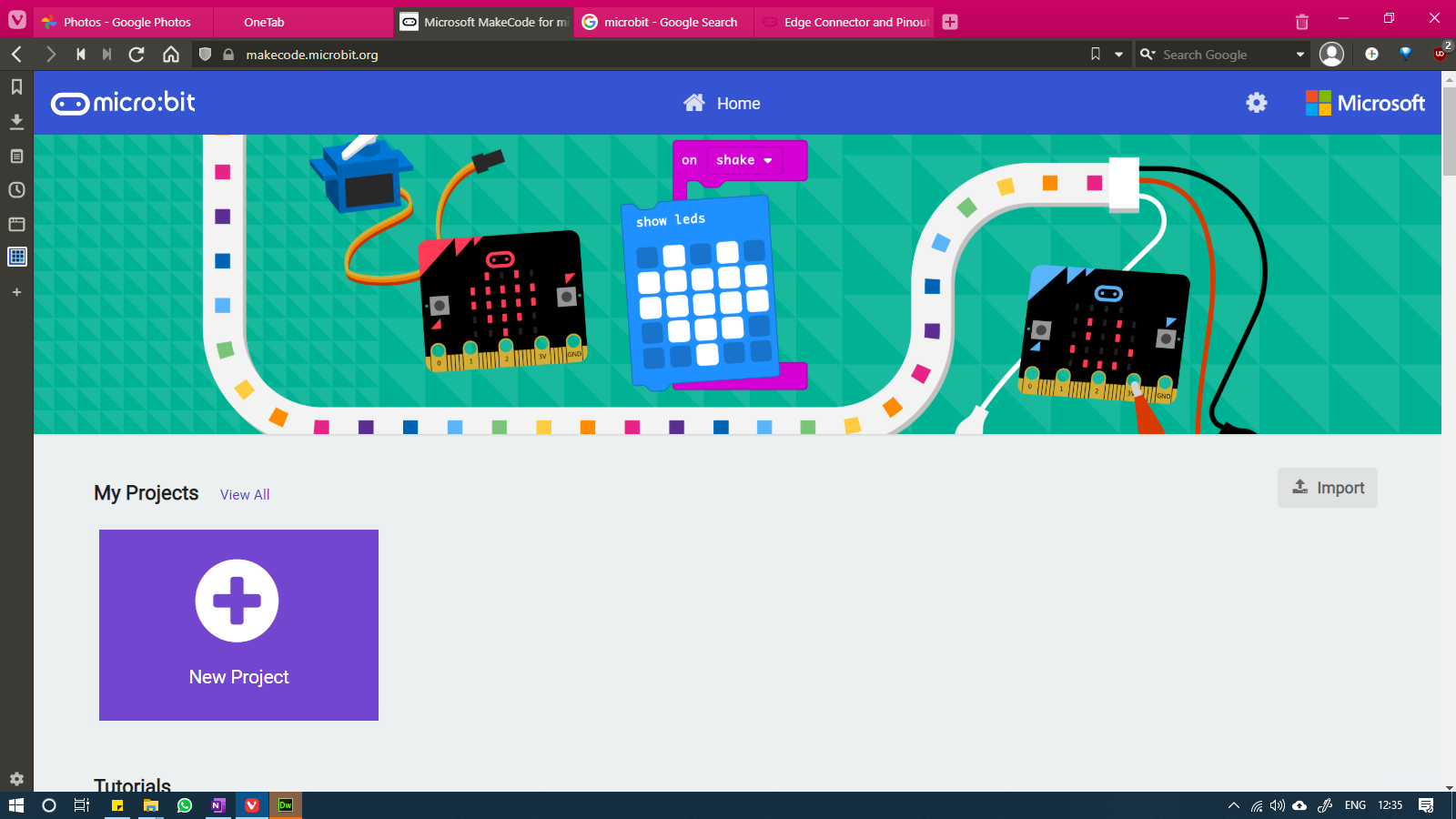
We were greeted by the following window:
After that Mohit made a simple program to turn on specific patters for specific button inputs:
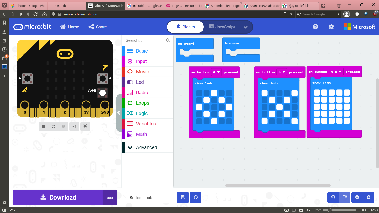
Hex code for button inputs
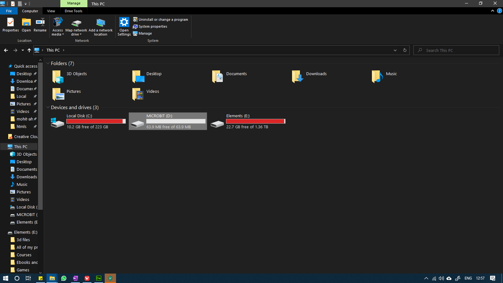
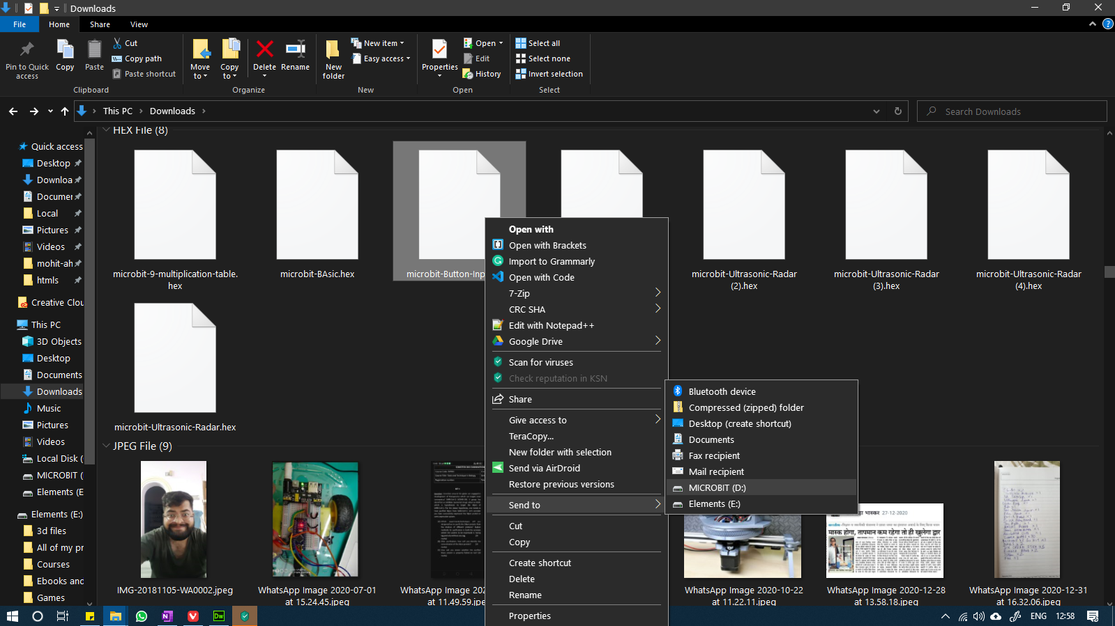
To upload the program to the board, we need to download the hex file from the website and then copy paste the file into the microbit's folder in the computer.
After uploading the code to the microbit, this was the output:
After this, we also tried a program that demonstrates the accelerometer of the microbit by changing the position of the LED based on the orientation in which we hold the board. Here is the program:
Code for moving LED
And here is the output from that program:
Raspberry Pi
Raspberry Pi is a family of single board computers which were made to teach computing to young learners. It made computing and experimenting with computing very easy since the board has a ton of GPIOs and costs very less as compared to a full fledged computer setup. Raspberry Pi has also been instrumental in teaching and spreading awareness about the open-source movement and the many benefits of using Linux.
Raspberry Pi 4
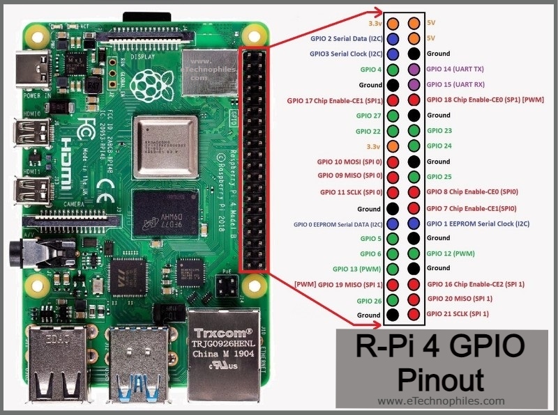
Throughout the years there have been many different models of the Pi with different specs, so this year we used the Raspberry Pi 4, 4GB version. These are the techical specs of the board.
- Broadcom BCM2711, Quad core Cortex-A72 (ARM v8) 64-bit SoC @ 1.5GHz
- 2GB, 4GB or 8GB LPDDR4-3200 SDRAM (depending on model)
- 2.4 GHz and 5.0 GHz IEEE 802.11ac wireless, Bluetooth 5.0, BLE
- Gigabit Ethernet
- 2 USB 3.0 ports; 2 USB 2.0 ports.
- Raspberry Pi standard 40 pin GPIO header (fully backwards compatible with previous boards)
- 2 × micro-HDMI ports (up to 4kp60 supported)
- 2-lane MIPI DSI display port
- 2-lane MIPI CSI camera port
- 4-pole stereo audio and composite video port
- H.265 (4kp60 decode), H264 (1080p60 decode, 1080p30 encode)
- OpenGL ES 3.1, Vulkan 1.0
- Micro-SD card slot for loading operating system and data storage
- 5V DC via USB-C connector (minimum 3A*)
- 5V DC via GPIO header (minimum 3A*)
- Power over Ethernet (PoE) enabled (requires separate PoE HAT)
- Operating temperature: 0 – 50 degrees C ambient
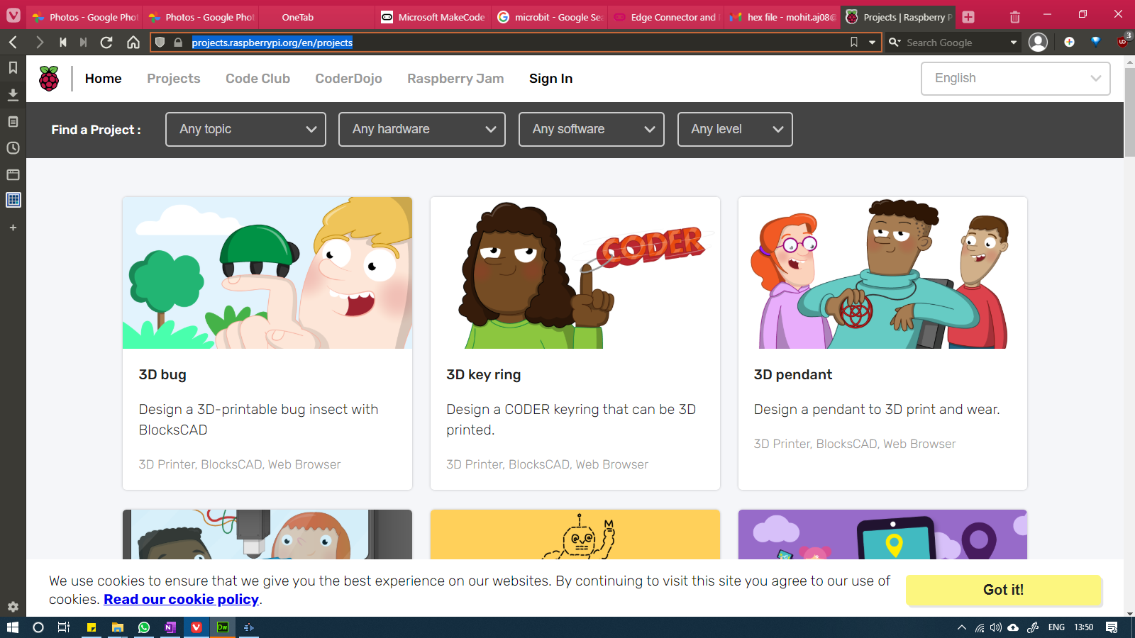
We had a lot of fun using the Raspberry Pi. We did a bunch of different programs by following the examples given on the raspberry pi's projects page: https://projects.raspberrypi.org/en/projects
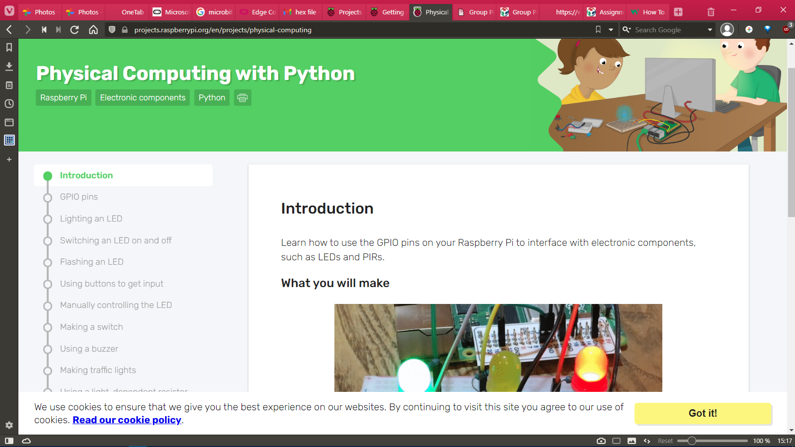
We decided to do Python on Raspberry Pi, specifically using Python to control the GPIOs of the Raspberry Pi
To begin, we followed the instructions provided on this page:https://projects.raspberrypi.org/en/projects/physical-computing
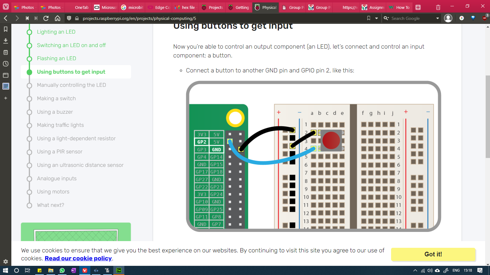
We first went with the Button testing circuit. We connected the circuit to the Raspberry Pi according to the following diagram:
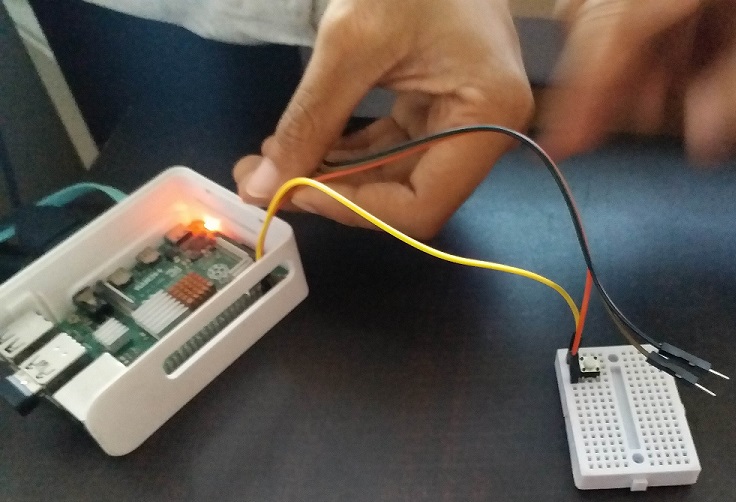
This is what it looked like:
Then we used the Thonny Python IDE which is installed by default in Raspberry Pi and started writing the code to print "You pushed me" everytime one presses the button. And then to run the program, we simply clicked on the Run button of the software. You can see the output of the program in the bottom portion of the window.
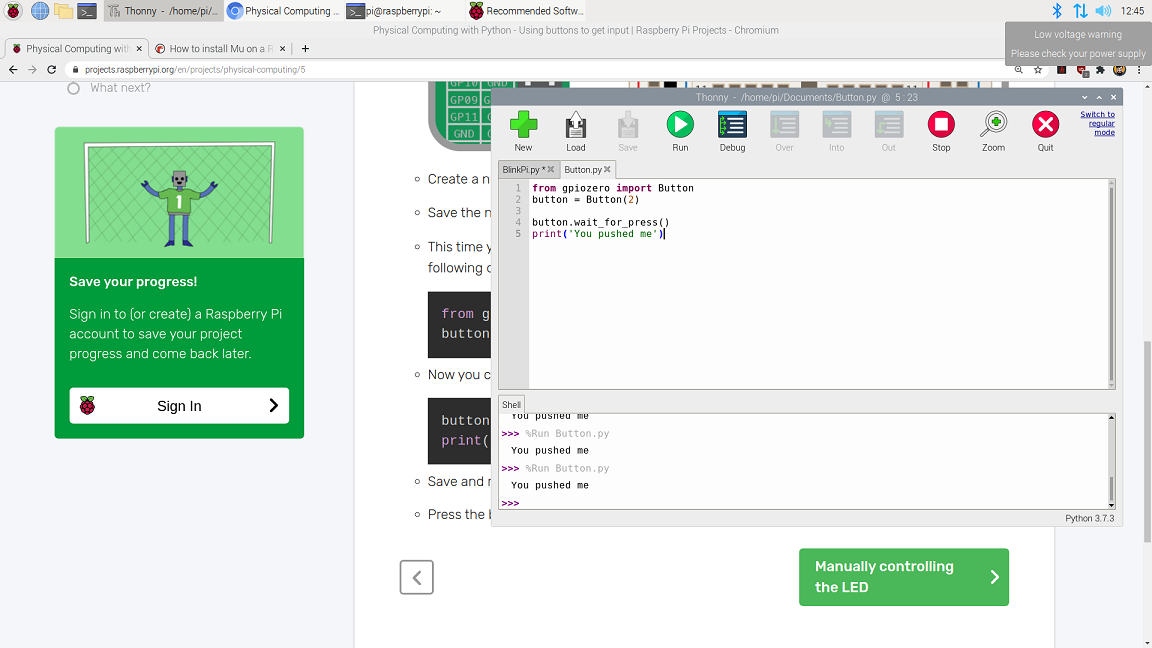
Code to use button with Pi
After that, we modified the code to print a message and turn on an LED for 3 seconds when we press a button.
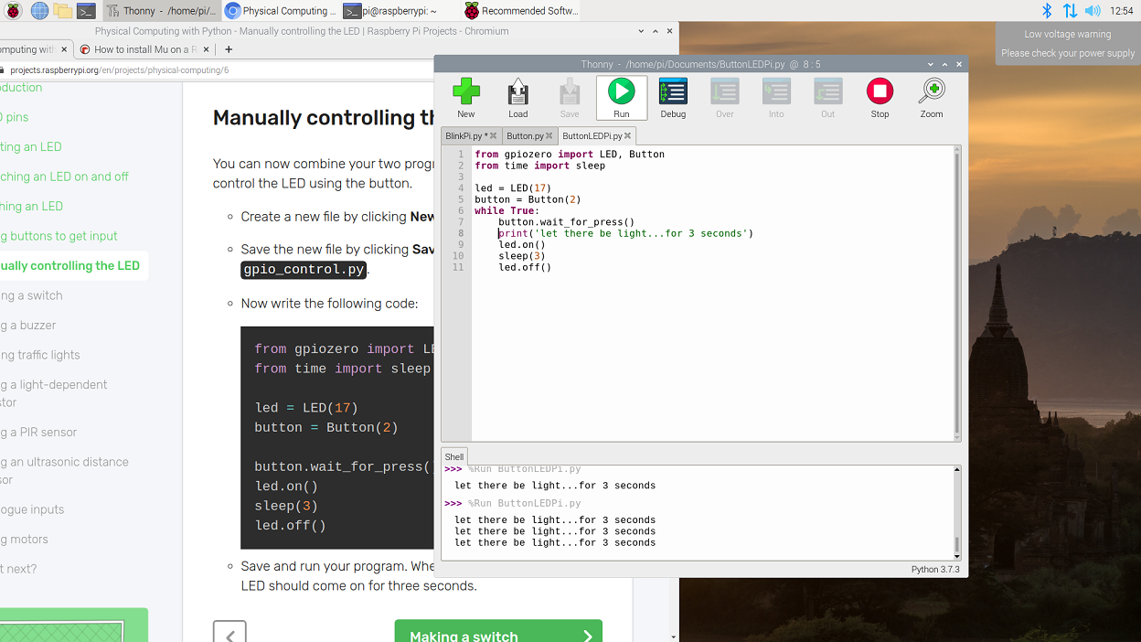
Code to control the LED with a button on Pi
And this was the output of the program:
And with that, the group project was concluded.