Task to be Perform for this week
Group assignment:
Compare as many tool options as possible.
Individual Assignment:
Write an application that interfaces a user with an input and/or output device that you made
Learning outcomes
1) Interpret and implement design and programming protocols to create a Graphic User Interface (GUI).
Introduction Interfacing and Programming Application
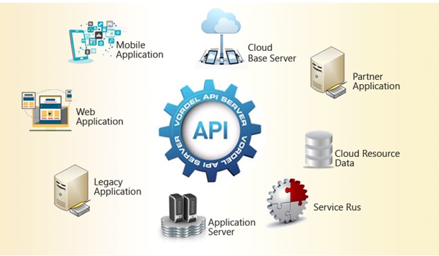
In computing, an application programming interface (API) is an interface that defines interactions between multiple software applications or mixed hardware-software intermediaries. It defines the kinds of calls or requests that can be made, how to make them, the data formats that should be used, the conventions to follow, etc. It can also provide extension mechanisms so that users can extend existing functionality in various ways and to varying degrees. An API can be entirely custom, specific to a component, or designed based on an industry-standard to ensure interoperability. Through information hiding, APIs enable modular programming, allowing users to use the interface independently of the implementation. Reference to Web APIs is currently the most common use of the term. There are also APIs for programming languages, software libraries, computer operating systems, and computer hardware. APIs originated in the 1940s, though the term API did not emerge until the 1960s and 70s.Wikipedia
An Application programming Interface( API), It is the process of two web pages or the pieces of the software to communicate with each other.An API works as a middleman, taking the request from one piece of software, and then replying with the appropriate response from the other. Source:-link
About Group Assignment:-
The task for the week is to compare as many tool options as possible. Here we tried MIT App Inventor, Processing and Scratch.
For more details about the group Assignment CLICK HERE
Individual Assignment:-
The task for the individual assignment is to write an application that interface a user with an input and/or Output devices that we have made for our final project.So for Completing this task as I am going to use temperature sensor for my final project.So I have tried to work on processing software for monitor the values of temperature sensor, and also tried to develope the Application for Motitoring the temperature value. This App is developed by using MIT App Inventer.
Let's us discussed one by one how I have worked for this week.
1. Graphical User Interfacing ( GUI) in Processing App.
What is GUI:- A graphical user interface (GUI) is a type of user interface through which users interact with electronic devices via visual indicator representations.
Graphical user interfaces would become the standard of user-centered design in software application programming, providing users the capability to intuitively operate computers and other electronic devices through the direct manipulation of graphical icons such as buttons, scroll bars, windows, tabs, menus, cursors, and the mouse pointing device. Many modern graphical user interfaces feature touchscreen and voice-command interaction capabilities.
About Processing App:-
Processing is a flexible software sketchbook and a language for learning how to code within the context of the visual arts.It is an open source software or the graphical library and integrated development environment (IDE) built for the electronic arts, new media art, and visual design communities with the purpose of teaching non-programmers the fundamentals of computer programming in a visual context. integrated development environment (IDE) built for the electronic arts, new media art, and visual design communities with the purpose of teaching non-programmers the fundamentals of computer programming in a visual context.
Some Features of Processing Software:-
- Processing includes a sketchbook, a minimal alternative to an integrated development environment (IDE) for organizing projects.
- Every Processing sketch is actually a subclass of the PApplet Java class.
- When programming in Processing, all additional classes defined will be treated as inner classes when the code is translated into pure Java before compiling.
- Processing also allows for users to create their own classes within the PApplet sketch.
- Interactive programs with 2D, 3D, PDF, or SVG output
So using this processing software I have tried to design the graphical interface like meter which can read what ever the data of the temperature sensor availble on serial monitor of arduino IDE Which can be shown in meter continiously.
Starting of this week our colleague Mohit introduce us little bit about processing software and we have started worked on it.
First we have downloded this software from this LINK
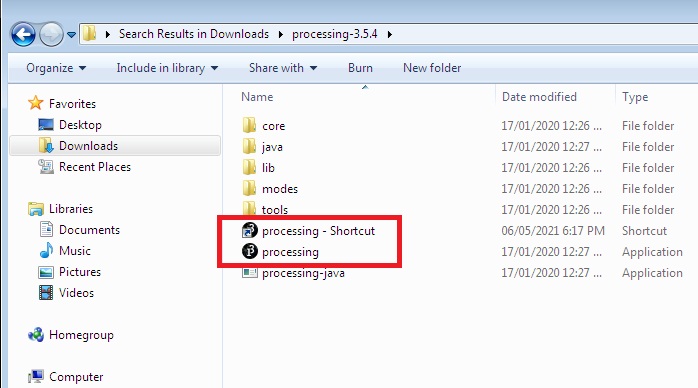
After downloading extract the file.You will find processing 3.5.4 folder which contain the processing appliction file.Click on it to run processing application.
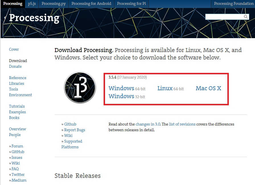
This software available for various types operating system as per our choice. I am working on windows-7 32 bit so I have selected this and download it.
After extracting this file we need to click on here
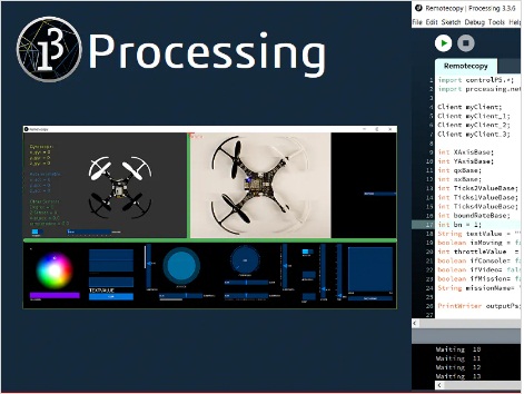
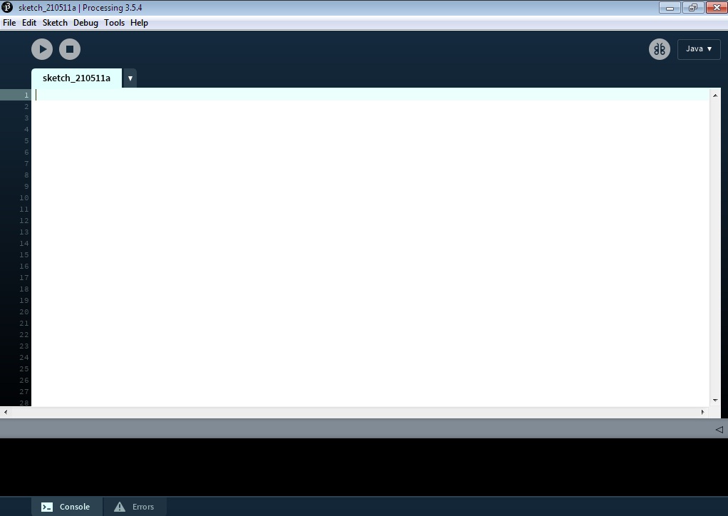
After running the processing software we can see the processing environment like shown in below image.
Before going to work on this software I have reffered some tutorial from this LINK
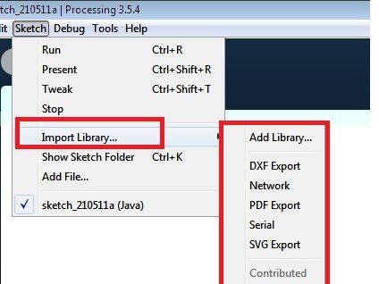
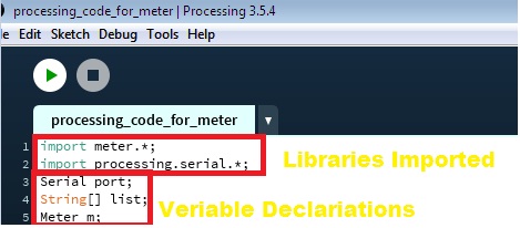
So, In this processing libraries contain some importent things before going to work on it.i.e required libraries should be import from "Import Library" tool.
Some basic libraries has to be added while working on any program.
As want to develop the temperature Indicator like a meter which can display the value of temperature sensor on for developing this kind meter I have reffered this Link
Install the Meter Library in Processing
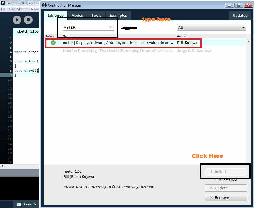
Then I need to install the meter library first in processing IDE, So for installing the meter library go to sketch menu then click on import library option >> then go to Add library option and type meter in serach box The meter library by Bill Kujawa should appear.Select it and press the Install button, at the lower right. Close the window after the installation completes.
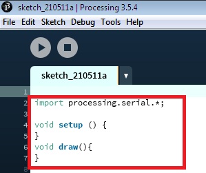
After installing libraries and all I have proceed for the programming.I tried to getting the data form microcontroller board over to the processing meter which can display the data available on serial monitor of arduino IDE on the designed temperature meter in processing.
Then I need to declear the veriable to hold the value temprary, then myport is declear as a veriable /object of serial type
Then need to write "Void setup()" Generally Void setup is technically a function that you create at the top of each program. Inside the curly brackets is the code that you want to run one time as soon as the program starts running.
As this is initial setup environment for every programm so I have used here for setup() size of window,background color,initilize the port, baud rate, set font size all dimentions and the properties of the meter widowa has to be initilize first for this I have reffered this Document link
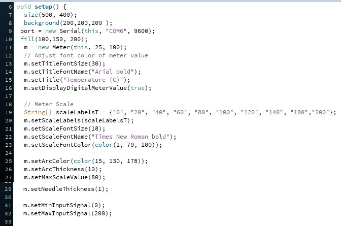
Here, I have used serial port COM-6 Becuase My microcontroller board is connected to this USB port this may vary as per USB serial port
Then need to write " Void draw() " the contain in this syntax used loop forever ,until stop.It is use to exicute the program continiously.
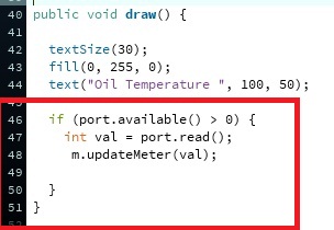
I have define the text size first, then fill color code, as meassuring the Oil temperature written in text with alignment.
Then "if (port.available() > 0)" Then this conditions for if any data available on serial port gretter that zero it will store in the "int (Interger) val" veriable. and the also the read update this veriable on meter also using "m.updateMeter(val);" command.
Note:- This code I have reffered from this website and made the necessary changes as per need.
After Understanding this program logic I had to go forr setup and read the sensor data from Atmega328p board to Meter by interfacing .
For interfacing with processing software, Hardware requirement as follows
1. Atmega328P Microcontroller Board.
2.PT1000 Temperature Sensor.
3. Bread Board.
4. Connecting Wires.
5. Thermameter for varifivation of temperature Values.
6.4.7kOhm Pull up Resistor.
7. Arduino Uno Board.
8. FabISP Programmer.
The Overall Connections digram is as shown below.
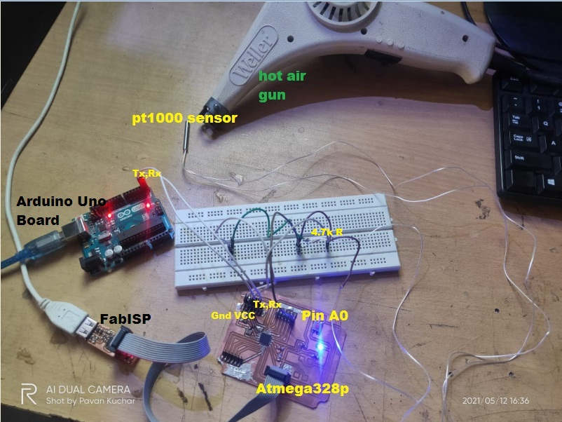
The discription of the circuit:-
1. First Connect the Fabisp programmer to the atmega328p board.
2. Connect the RX,TX pins of Atmega328p Board to arduino uno Board for reading the data on serial monitor.
3. Connect the Vcc from the atmega328p board to first terminal of 4.7kohms Resistor.
4. Then Second terminal of resitor is connected to one terminal of pt1000 temperature sensor.
5. Second terminal of pt1000 sensor is connected to ground wire from atmega328p board.
6. Analog pin A0 from microcontroller board is connected to junction of 4.7k and sensor terminal
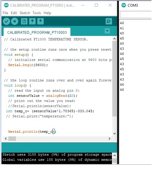
Once the connection are made I need to upload the program using arduino IDE with the help of FABISP in ATMEGA328P Microcontroller Board.
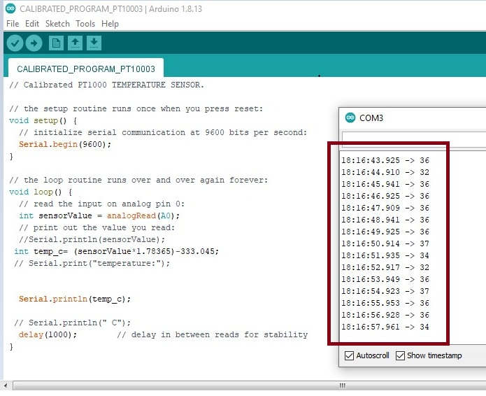
This is the program that I have uploaded first in atmega328p
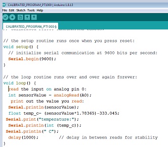
But Here I have faced the problem serial monitor of arduino IDE did not showing the proper reading, showing some garbage value. I throught that connections are not proper(Might be due to loose connections), I checked once but not resolve the issue. not wroking at all.
This kind of values displayed in serial montor.
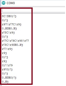
I didn't understand what actually happen I tried number of time , aslo burn the boot loader in this case,but not resolve the problem.
After that,I discussed this issue with mohit and checked the connection and all things and also the board which are selected in arduino IDE.
The configurations of board we have selected shown in below image.
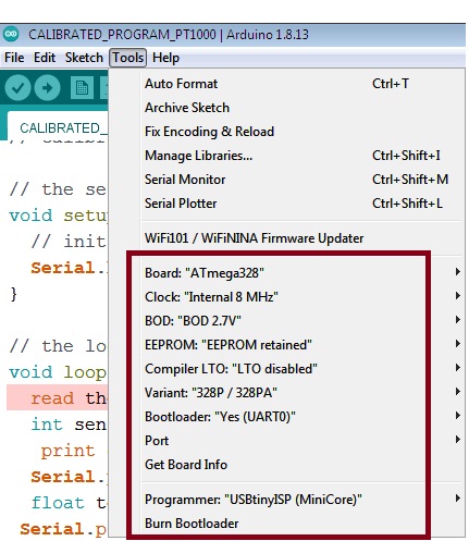
At this same configurations of board in Input devices week I have got the reading but here not. Mohit told me this issue is surely due to programmer clock frequency that we have selected in the board configurations.
Then we have select the 20MHz external clock that I have already connect the crystal crystal oscillator 20MHz So we have tried on this configuration.
Then we have burn the bootloader again by chossing this configurations. and upload the program.
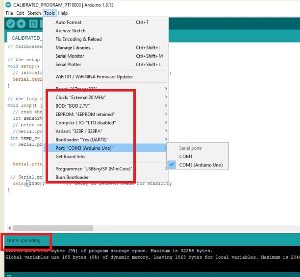
Now the serial monitor able to read the proper reading and the error get resolved.
Now I need to proceed for interfacing with processing software.
Then I have open the processing software and open the meter code which i have made. and run it.
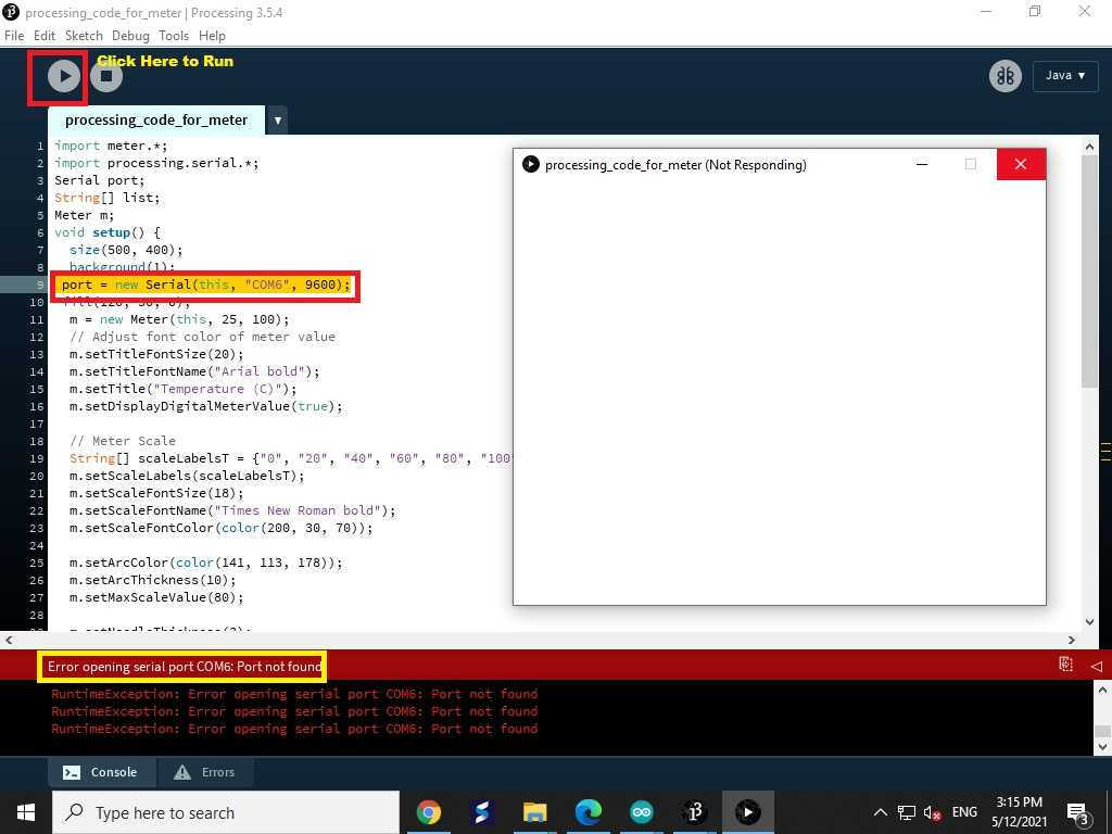
Here, I got an error "COM-6 was not found" In this case we need to write same com port here which we have selected for your microcontroller board is connected.
Then I have changed it from com-6 to com-3 as my atmega328p board is conneted at com-3 and run the code again.
Note:- When you run the code in processing the com port of arduino IDE must be closed other wise it shows the error com port busy.
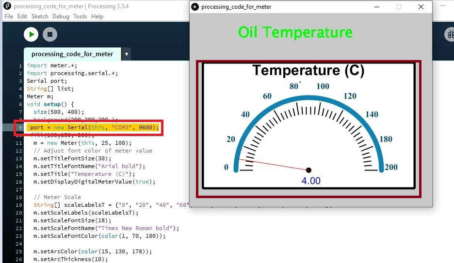
Then I have run the code and meter is displayed on screen but not showing the actual value which have read by serial monitor, showing some what fluctuating value.
Note:- This is because of in arduino IDE I have written the "serial.println()" this command will send the string data and here processing will not able to read this data properly so instead of "serial.println()" we need to write "serial.write()" command the processing will read this properly.
Then I have edit the code and upload it again.
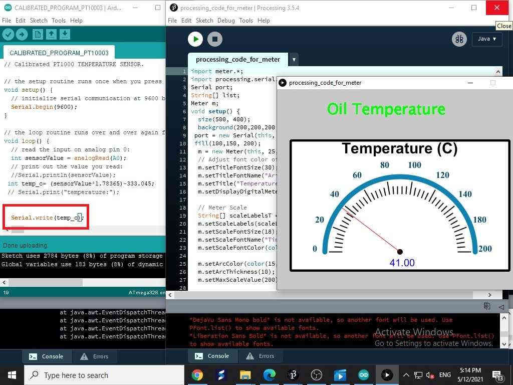
But in serial monitor of arduino IDE, Not printing the value because of "serial.write" command use to see the data on serial monitor need to write "serial.println()"
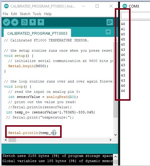
This is only to checked the same values will read by the meter or not.
This is how I have setup this
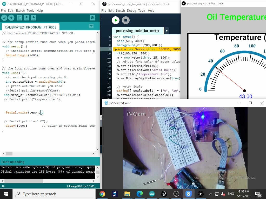
Here, used of hot air gun to increase the temperature value.
The Video shows the overall interfaing with Processing Software
App Developement In MIT App Inventor
The App is develope by using MIT app inventor ,MIT App Inventor is an intuitive, visual programming environment that allows everyone to build fully functional apps for smartphones and tablets. Those new to MIT App Inventor can have a simple first app up and running in less than 30 minutes. And what's more, there is a blocks-based tool facilitates the creation of complex, high-impact apps in significantly less time than traditional programming environments. The MIT App Inventor project seeks to democratize software development by empowering all people, especially young people, to move from technology consumption to technology creation. for more detail Please go through Website. It is an open source software to develope the any kind of app just we need to do login with our google account.
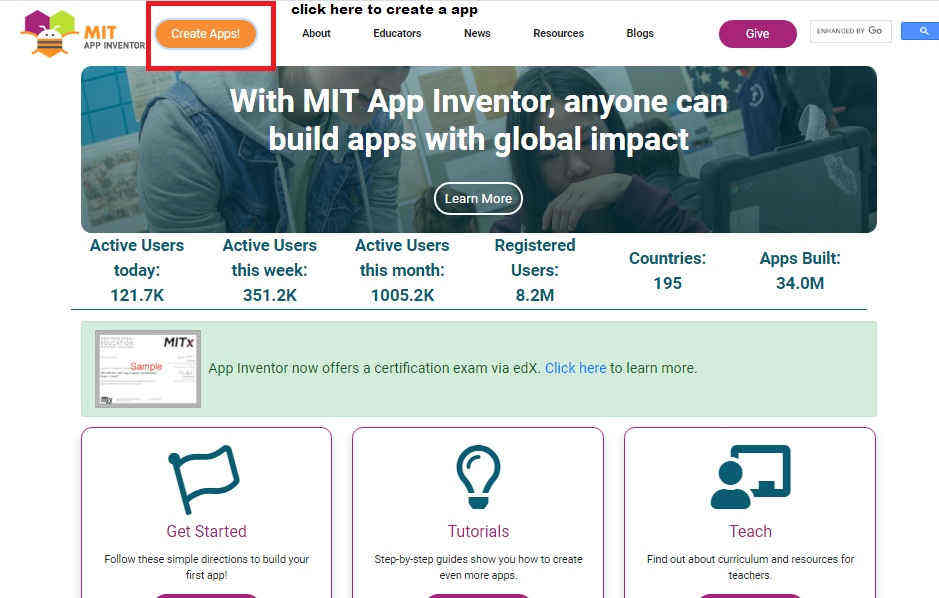
Need to continue with your google account.
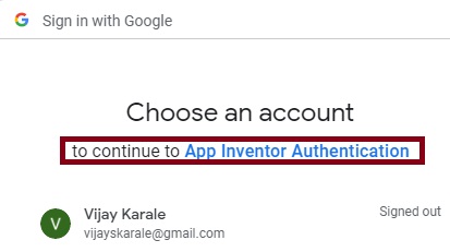
After sign in with google account I have started to develope the app.
When you login with your google account the following kind of window will open
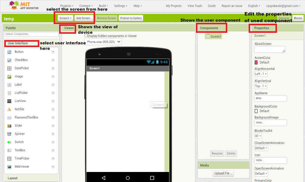
The various section displyed on windpws as follow.
First we need to click on new project and assign the name as you want.
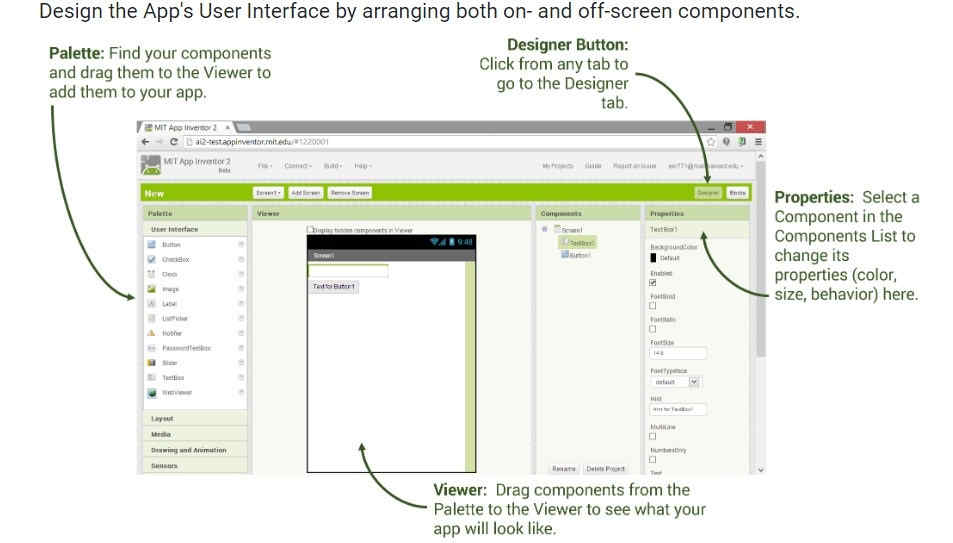
Basically this app windows divided into four parts the discriptions as follow.
1. Palette(At top of left side): Here we can see the different options like, user interface, layput, media, drawing and animation, maps, sensor, social etc. which can work as css like in website development.
2. Viewer (At center of window):Here we can set the size of app as per our need the options availble are phone size,tablate size and the monitor size.
3. Component (At right side):It can shows the palette used for apps means whatever lables buttons and component we are picked for building the app.
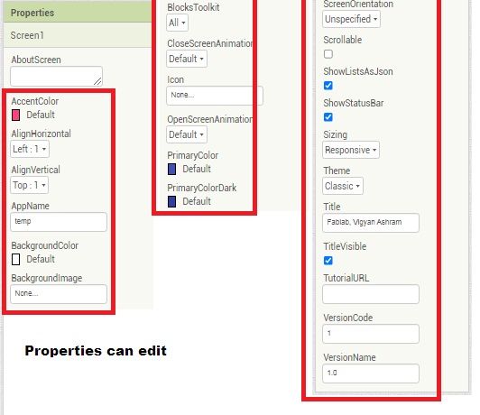
4. Properties (At right side): Here we can specify the properties of the components such as the font, height and width, background colour or image etc.
5. Screen (At top): There is a button for to show the screen number, to add new screen or to remove any screen.
Once understand the basic about this application I have started to develope app.
Steps For Designing The APP in MIT app Inventer.
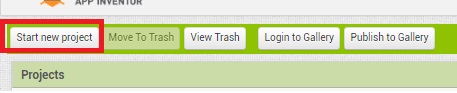
1. Go to my project.
2. Click on start New Project.
3. Write the project name as your want .
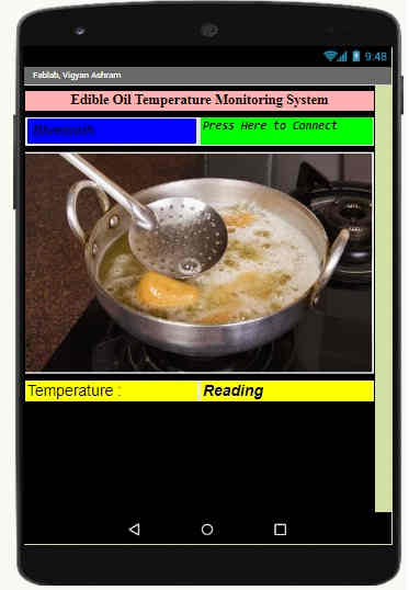
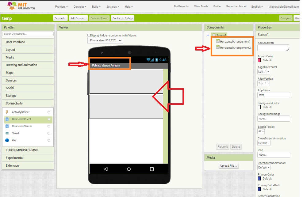
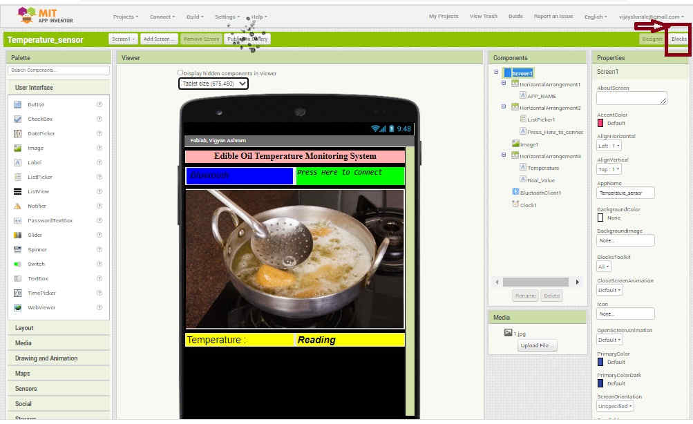
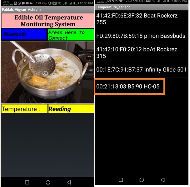
As wanted to develope the app like it shows the tempreture reading which can interface with sensor with the help of HC-05 bluetooth module.So I started selecting the component from user interfacing and the layout menu.First I have edit the screen name with fablab,Vigyan Ashram., Project name is temperature_Sensor Then take the two horizontal arrangement from layout.
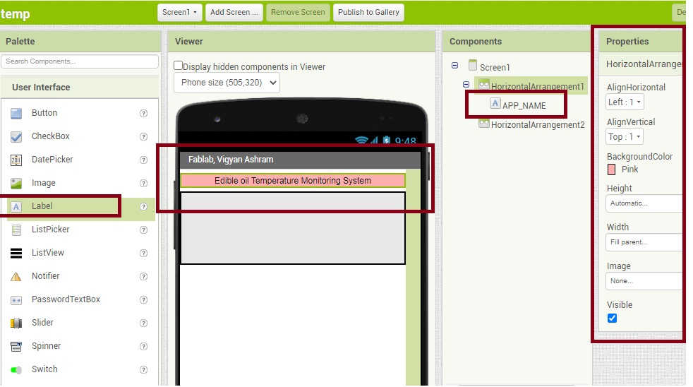
Then by taking the label option I have given the App_name as shows below, by changing its properties and text alingment as well.
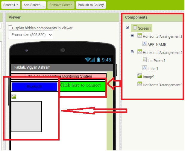
Then In the same way, I have taken the component one by one and edit using properties as per my requirement.also by adding one image source.
Now the desined part is ready, I need to switch for block programming by clicking the options block.
As I want to run this app using bluetooth, So for programming I have reffered this tutorial.LINK
Then,Go for block level programming:--
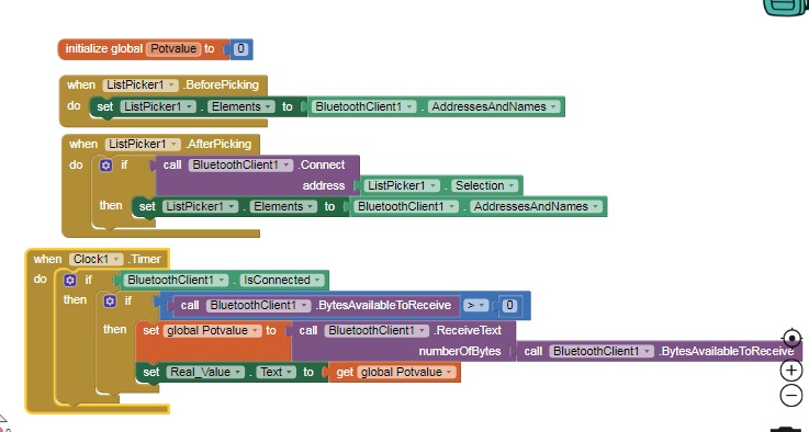
Go to Screen1 menu and click on list picker and drag the block code. and Similarly drag the control structure from another item and do the same accordingly
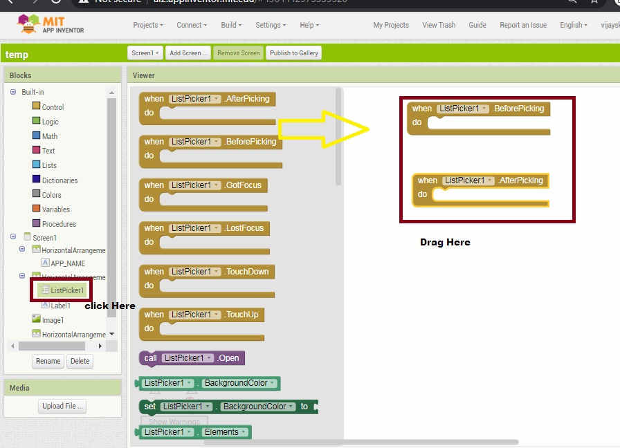
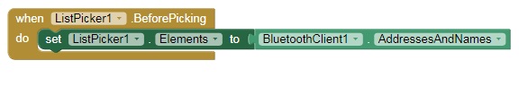
Then Write a when - do block i.e.before picking
-Set listpicker1 elements to bluetoothclient with addrees name.
-When we click on label2 show connected.
- Give text color.
Then drag the block when listpiker -after picking and picking In Do block connect bluetooth with
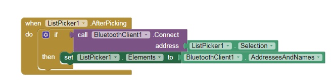
Then, as I wanted to to read the temperature values sensor by the temperature sensor by connecting bluetooth so finally I need to receive the data from sensor by connecting global potvalue block, for reading the actual value when bluetooth is get connected
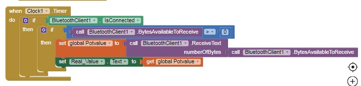
Lastly, bluetooth connected start receiving the data from sensor.This is the overall code.
Then , Once i finished above code again switch from block to design and Go to Build -> click on app (provide QR code for.apk) for fetching this app into your smart phone
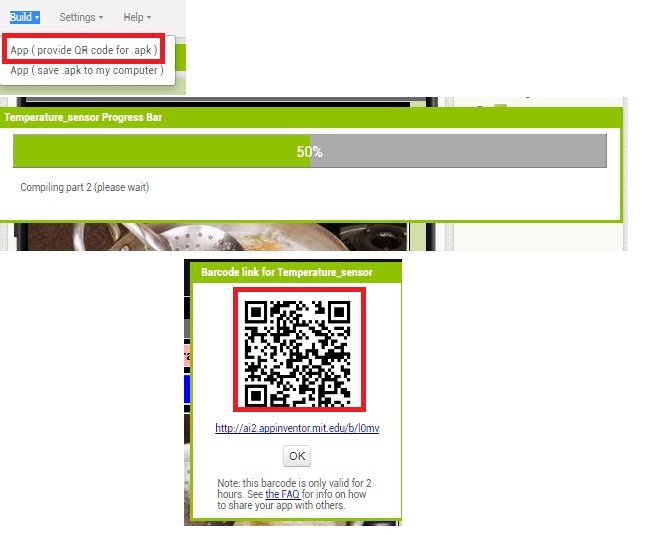
For Scanning this QR code we need to install the MIT inventor App in our pesonal mobile.
After installing this app we need to open the app and sacn the QR Code.
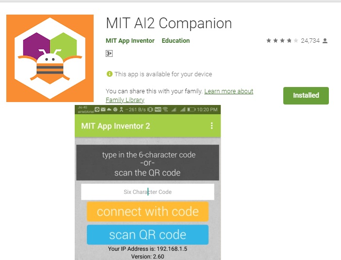
Then next step is to download and installed this app.
Once App is installed succesfully open it once and checked whether it is working or not(Searching the bluetooth or not).
Once it working properly go for the cicrcuit connections and tried to interface with this App.
For connecting the circuit I required Atmega328p board, Pt1000 temperature sensor.and HC-05 bluetooth module.
The Below figure shows the Overall circuit Diagram.
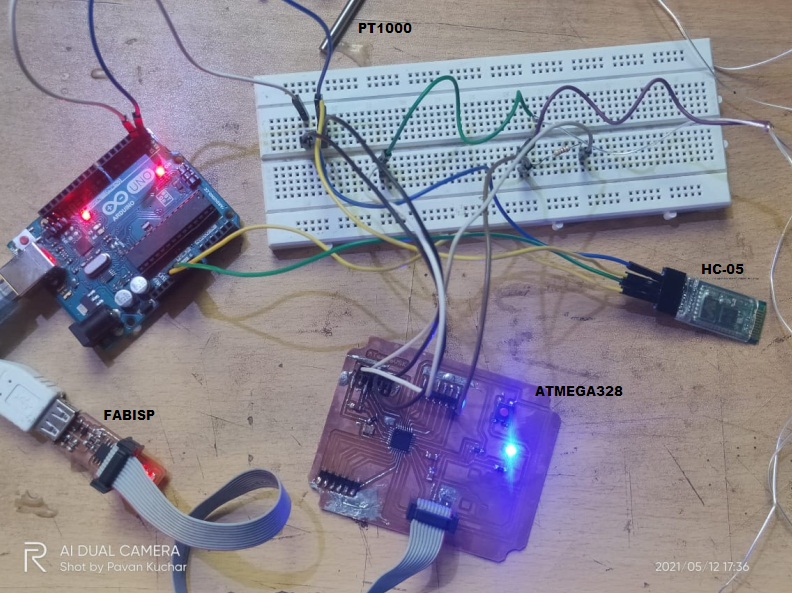
The circuit discriptions as follow.
1. Connect the Fabisp Programmer to Atmega328p Borad through AVRISP header pin.
2. Then Connect the RX,TX From arduino board to RX,TX of Atmega328p Board.
3.Then connect the VCC to one terminal of 4.7kohm resistor,and the second terminal of resistor connected to first terminal of PT1000 Temperature sensor , second terminal from PT1000 Sensor connected to GND of atmega328p Board.
4. Then analog pin A0 of atmega328p connected at the node point of resistor and pt1000 sensor.
5. Then four wire from HC -05 Bluetooth module i.e. VCC,GND,RX,TX connected to VCC,GND,RX,TX of Atmega328p Board.
Once connect the circuit as per above said I had to upload the program in Arduino IDE.
Then Open and run the MIT app,Click on Bluetooth Button -> select/pair the bluetooth module, now its start showing the data on screen.
What I have Learned.
1. I have unsterstood about the different types of interfacing tools and languages
2. I have learned about the interfacing of atmega328p board and the input device with processing software.
3. Learned the App developement in MIT app Inventor tool.
4. Interfacing of MIT App with Atmega328p Board.
DOWNLOAD's
Download my original file here