Task to be Perform for this week
Individual Assignment:
Design and produce something with a digital fabrication process (incorporating computer-aided design and manufacturing) not covered in another assignment, documenting the requirements that your assignment meets, and including everything necessary to reproduce it.
Learning outcomes
1. Demonstrate workflows used in the chosen process
2. Select and apply suitable materials and processes to do your assignment.
Introduction
This week is intresting and creative in the lecture Neil told the basic requirements for this week's assignment are we have to design something,it should include any machine process,it should not done in any before assignments. Again this week was totally different than other week were we can explore our knowledge of digital fabrication as per interest. For this week i have decidesd to explore the Plasma cutting machine and Ebroidery machine availble at our Fablab at Vigyas Asharam. as our final project is going on so I have worked on design and cut the part of project.
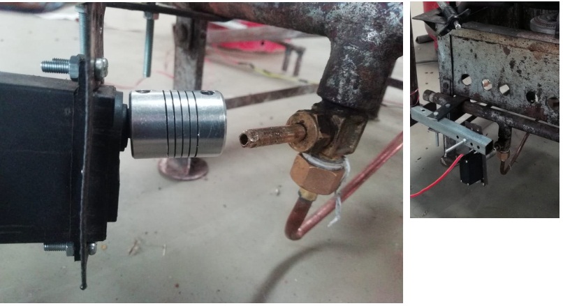
Designing of Servo Motor Holder In freeCad Software.
My final Project is Edible oil Temperature controller So for controlling the flame of LPG i am using the servo motor. I have to make the arrangement like the servo motor can fixed to the LPG Knob so I have measure the dimmentions and tried to designed the perticular holder to servo motor.
First I have measure required the dimentions so that servo motor can easily fix with the holder.
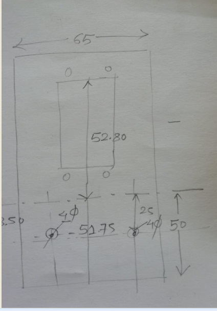
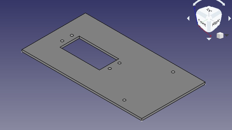
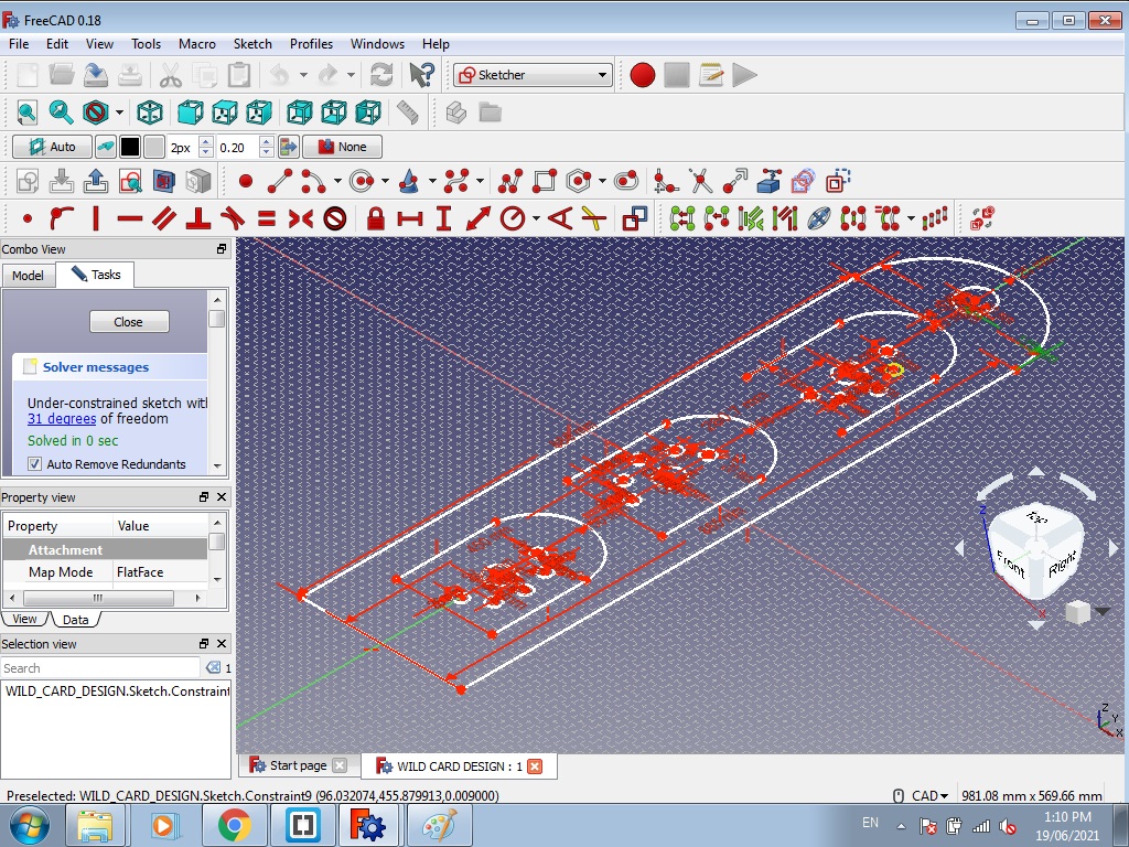
Then I have tried to designed this part in freeCad Software.
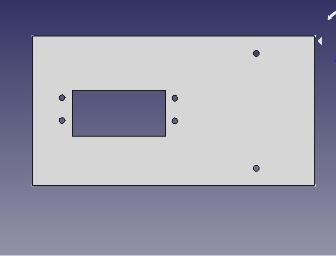
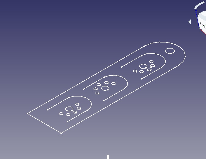
This is the design of servo motor holder as I am going to use servo motor in the final project I required this kind of holder by using metal I have cut it using plasma cutter.
Desinging of Magzine Holder In FreeCad Software.
For this Wild card week i have tried to designed one more parts that is magzine holder designed in free Cad Software and bend it using bending machine and also done the paintaing to this design which is very use for our FabLAB at vigyan Ashram
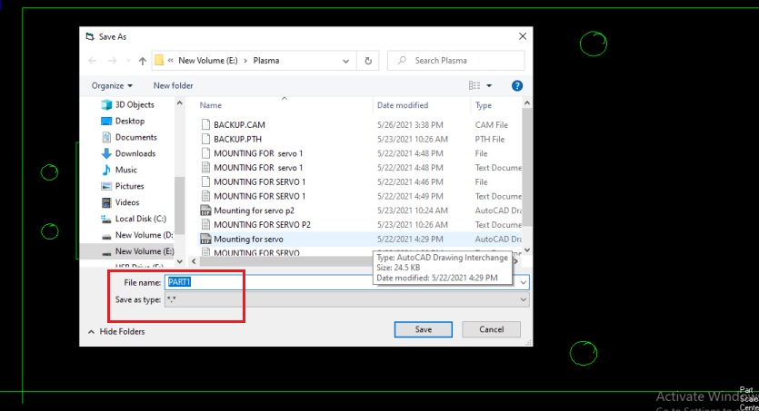
Then I have save the above design in .dxf format
Once the dxf file is ready then cut it by using plasma cutting machine.
Then I have cut this part using plasma cutter machine.
For plasama cutting machine required .TXT file so we have convert .dxf file into .TXT file. Procedure to convert .dfx file into .txt file expalain as follow.
About Fastcam Software:-
FastCAM® CAD CAM Software for Plasma, Oxy, Laser & Waterjet is a total NC solution for metal shape nesting and cutting; You can Draw, Path, Nest and Cut from the one system. FastCAM® allows people at a shop floor level to start profile cutting with the minimum of training. The FastCAM® System has been designed to draw, nest and cut metal as simply and efficiently as possible. Ease of use is as important as the high levels of materials utilization and optimization the software provides. FastCAM® is more affordable and far less complex than other systems. Easy Editing & Verification of geometry combined with one step nesting makes the system instantly productive.(Wikipedia)
For generation of g-code converting the .dxf file into the .txt file "FASTCAM" Software used.
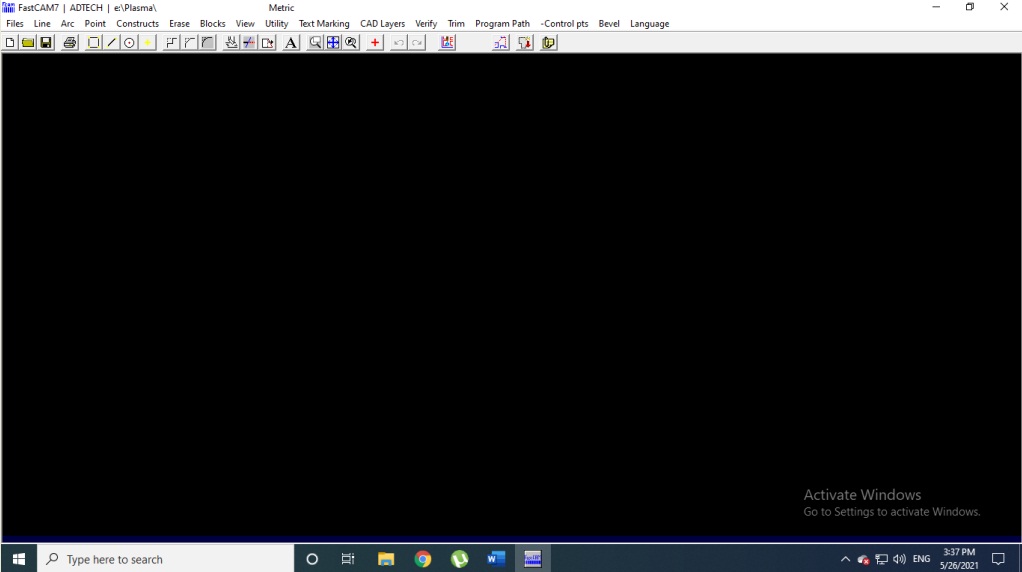
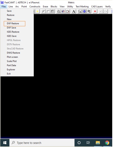
1. Open the fastcam software this kind of window may open Initially.
2. Then Go to file menu and click on DXF restore option.
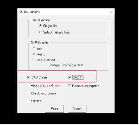
3. In the opening window of “DXF Option” select file, DXF file unit and tick on “CAD clean” and “CAD fix”. Click on enter
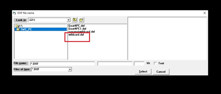
4. Then it will open the your Original files which is saved in specific filder, So click the file and open it. I have open my desined file.
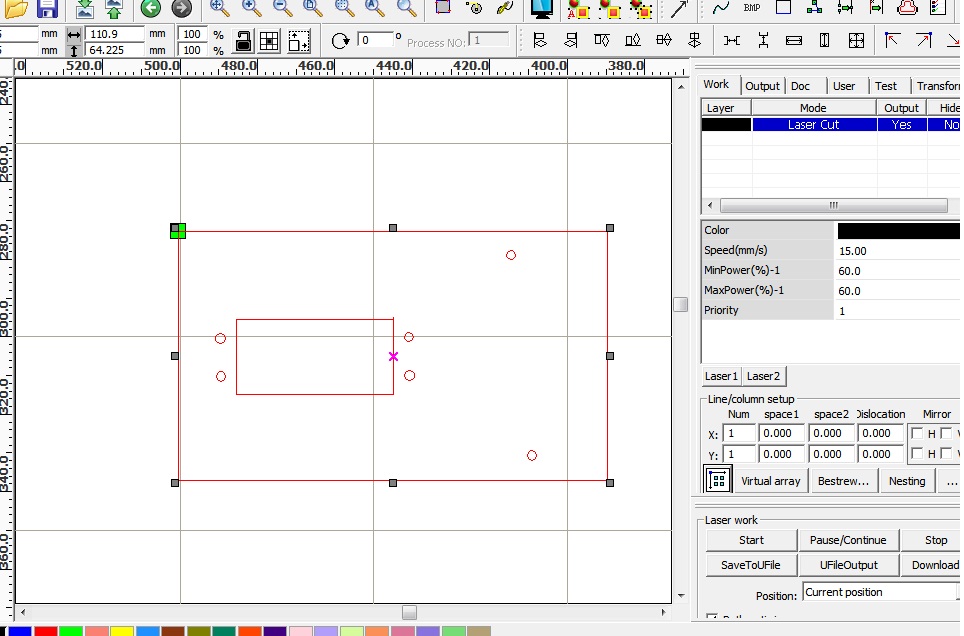
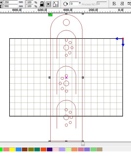
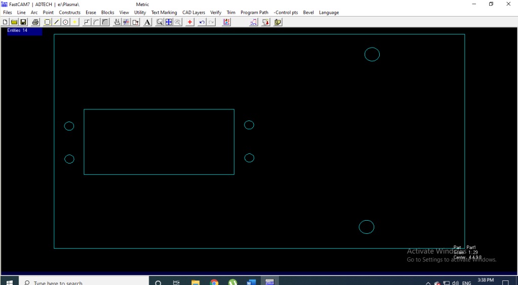
5. The DXF file is open in the FastCAM software as shown below.
6. Then Go to the program path option available in menu bar click on that in drop down menu Click on fastpath option.
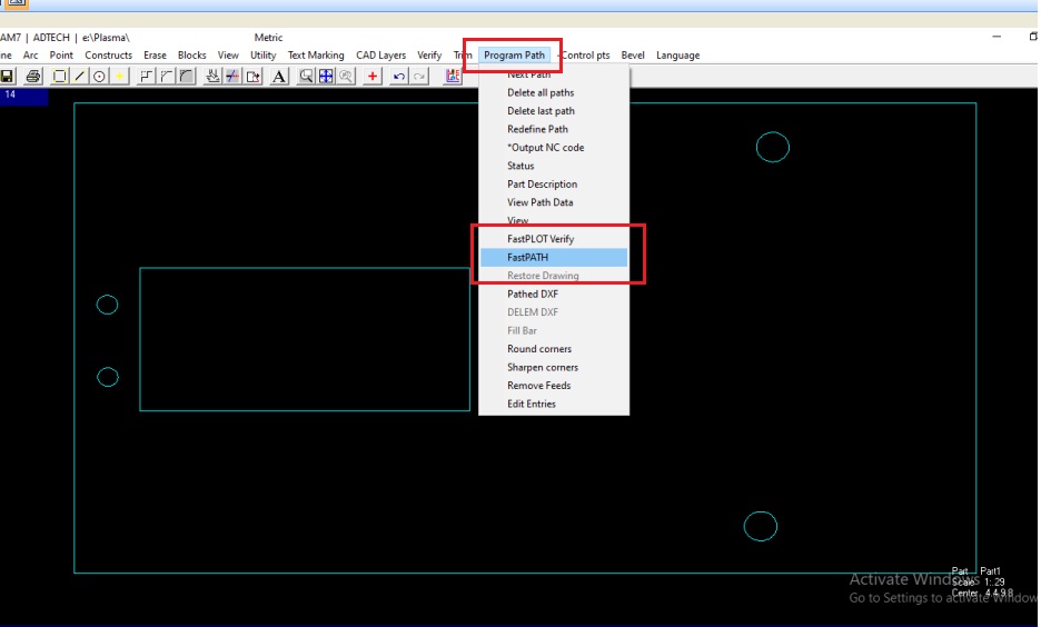
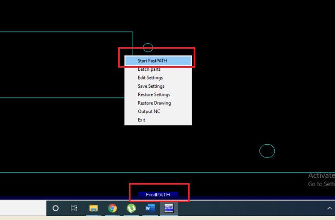
7. Then the options will open start fast path mean it will start the geneartion of G-code required for the plasma cutter machine.

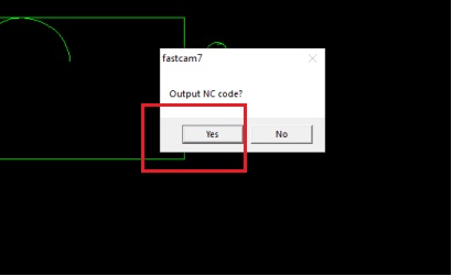
Click on yes option.
This is the final G-code generated using "FASTCAM" software.
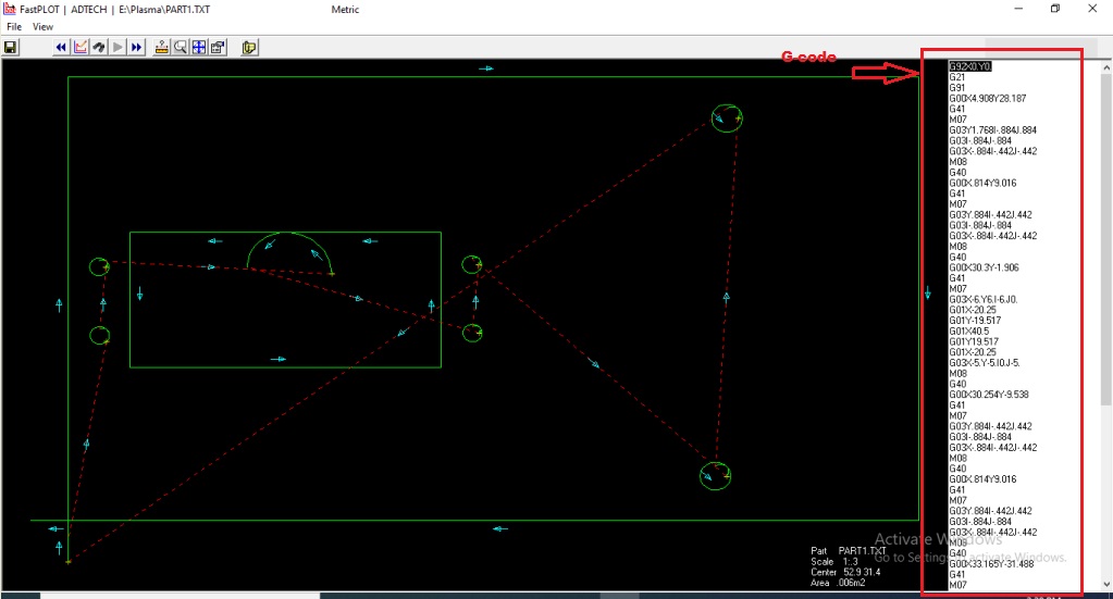
Once the G- code Generated succesfully we need to go for give this g-code to plasma cutter machine.
About Plasma Cutter Machine.
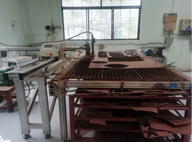
The plasma cutter machine which we are having in our Fab lab is Smart III porable table CNC cutting machine.Basically this machine based on F4 concepts i.e.Friendly in transportation, frieindly in installation ,friendly in operation,friendly in maintenance.The cutting area is 1500 x 3000mm and table structures are more precision.This is a dual drive system,that can handle more weight.This machine comes with high precision dual shaft linear guide.
How Plasma Cutter Machine works?
Plasma cutting is a process in which electrically conductive materials are cut through by means of an accelerated jet of hot plasma. Typical materials that can be cut with a plasma torch are steel, stainless steel, aluminium, brass, copper and other conductive metals. Plasma cutting is widely used in manufacturing, automotive repair and restoration, industrial construction, salvage and scrapping. Due to the high speed and precision of the cuts at low cost, plasma cutting is widely used from large industrial CNC applications to small hobby companies where the materials are subsequently used for welding. Plasma cutting - Conductive gas with a temperature of up to 30,000°C makes plasma cutting so special
The basic process in plasma cutting and welding is to create an electrical channel of superheated, electrically ionised gas – i.e. plasma - from the plasma cutter itself through the workpiece to be cut, thus forming a finished circuit back to the plasma cutter via an earth terminal. This is achieved by a compressed gas (oxygen, air, inert gas and others depending on the material to be cut) which is blown to the workpiece at high speed through a focused nozzle. Within the gas, an arc forms between an electrode near the gas nozzle and the workpiece itself. This electric arc ionises part of the gas and creates an electrically conductive plasma channel. As the current from the cutting torch of the plasma cutter flows through this plasma, it gives off enough heat to melt through the workpiece. At the same time, much of the high-speed plasma and compressed gas blows the hot molten metal away, separating the workpiece. Plasma cutting is an effective way to cut thin and thick materials. Hand torches can usually cut up to 38 mm thick steel sheet, stronger computer controlled torches can cut up to 150 mm thick steel sheet. Since plasma cutters produce a very hot and very localised “cone” for cutting, they are very useful for cutting and welding sheets in curved or angled shapes.
Parameter of Plasma cutter machine as follow.
1. Type Smart III plasma cutting machine.
2.Input voltage 110/220 V
3.Input Frequency 60/50 Hz
4.Input power 200 W
5.Controller LCD 7 ˝ color screen controller ( remote control is optional)
6.Effective cutting range 1500 (crosswise) X 3000 (lengthways) mm
7.Max cutting speed 4000 mm / min
8.Cutting thickness Plasma cutting: depends on plasma power
9.Cutting mode plasma
10.Cutting software FastCAM
Cutting mode plasma
HOW PLASMA CUTTER MACHINE WORKS.
Plasma cutting is a process in which electrically conductive materials are cut through by means of an accelerated jet of hot plasma. Typical materials that can be cut with a plasma torch are steel, stainless steel, aluminium, brass, copper and other conductive metals,Initially we have learnt that how to operate this machine from the operator at vigyan ashram, have understood all basic operation then work on it.
Some basic operation that we need to perform while cutting the any design on plasma cutter.
Initially we need to consider the parameter of Plasma cutting machine as per material thikness and by considering the kerf also.
I have consider the parameter and set it as per 0.8mm thickness of metal sheet, parameter is as shown below.
1) Input power :- 3 phase
2 ) Arc reference voltage : - 96 volt
3) Operating current: - 25 amp plasma generator.
4) Torch height : - 4mm
5) Cutting speed : - 3350 mm/min
6) Operating pressure : - 6.9 bar
7) Working process : - Cold role cold annealing (CRCA).
Note:- If pressure is less than arc, thickness will increases. If current is increases then arc radius also increases Voltage is 320 volt. we have to consider all this parameter while work on this machine.
Some parameter need to be consider as follow.
1. Kerf:- is the width of material (perpendicular to the torch and cut axis) removed during the plasma cutting process. Kerf is affected by three major variables.
2. Cutting Speed:- Faster cutting speeds with other variables constant will result in a narrower kerf. The kerf will continue to narrow until loss of penetration occurs. Slower travel speeds will result in a wider kerf until loss of arc occurs.
3. Cutting Amperage:- Increasing cutting amperage with the other two variables constant will result in a wider kerf. Continuing to increase current will widen kerf until the nozzle is destroyed. Lowering amperage will result in a narrower kerf, a more positive cut angle until penetration is lost.
4.Standoff:- Standoff is the distance maintained between torch and work-piece after piercing (while cutting). Most modern systems use an arc voltage feedback system. Increasing the arc voltage increases the standoff distance and widen the kerf. Continuing to increase standoff will eventually lead to loss of cut. Lowering standoff will lead to a narrower kerf and even- tually loss of cut.
Steps of operating Plasma Cutter.
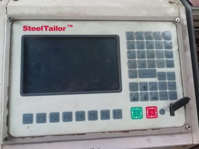
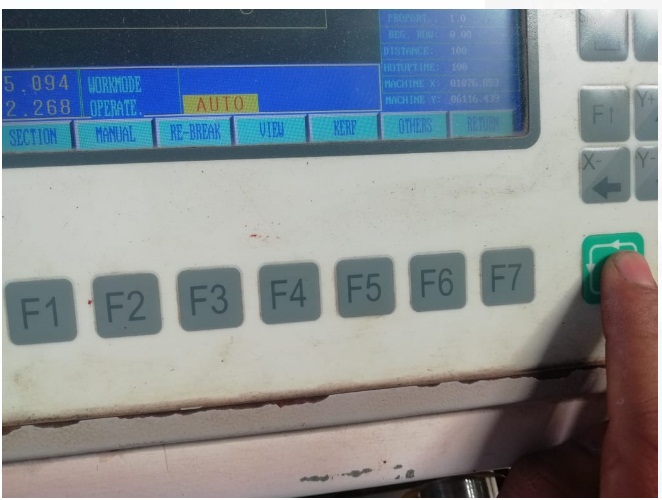
First we need to switch on the supply and Air compressor with control panel
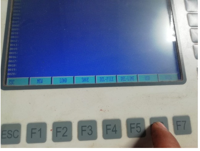
This is the main control panel display from this we can give the command to machine.
After switch on the supply we need to attched your USB drive to this panel and open the gcode.
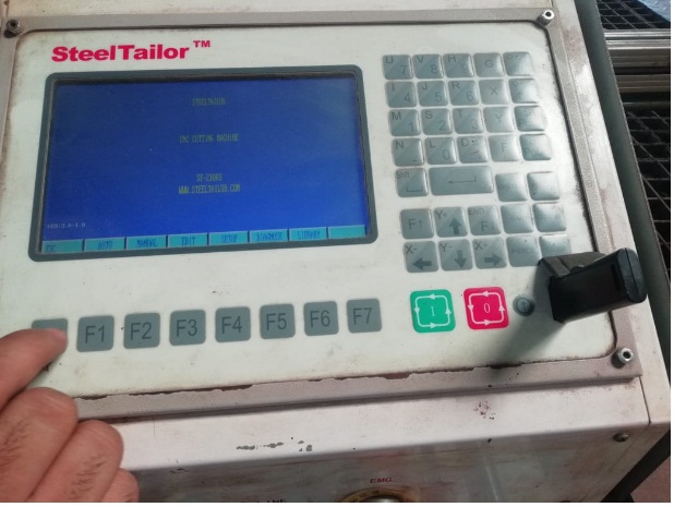
Open your file from USB so first load the USB by clicking on F7 button.
Then I need to open my txt file i.e. G-code by dropdown the curs0r
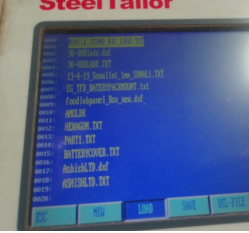
Then by clicking on load option G-code will open in your screen.
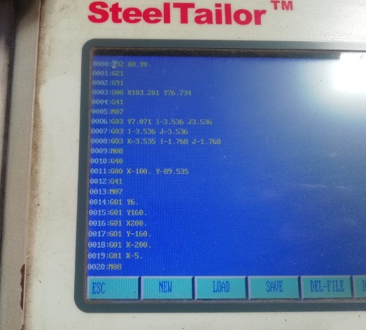
Then Press escape and open your file the file will open in your screen .
Then set your nozzel of machine as per your requirement manualy and press enter "I" key from control panel.
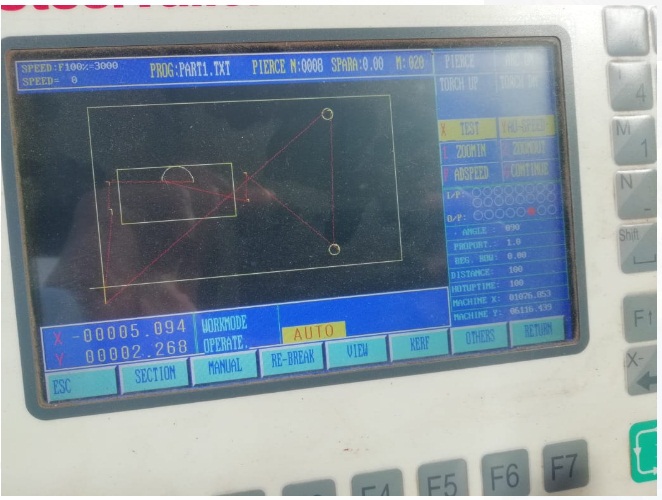
Then the below video shows the checking the frame of design.
After that I have cut the designed and its looks like
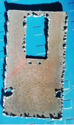
Here, after cutting by plasma cutter I have observed that the holes I that I have created in the designed not cut propely due to kerf value because the holes having dimeter in 2.5mm and when I calcultate the kerf it is near about 2.55 mm.Apox.
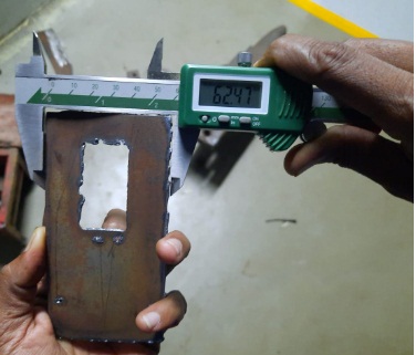
Here I have calculated the kerf it is found to be near about 2.53 mm because orinal size is 65 mm and after cutting is reduce to 62.57mm
Then I have resize the dimentions as per requirement and cut it again
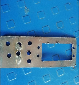
And finally attched the servo motor properly with holder.
Then I have cut the another design with this plasma cutter machine that is Magzine holder useful for vigyan Ashram Fablab
The details Video of cutting process of this designe as given in following video.
After Cutting this part took some shot as below
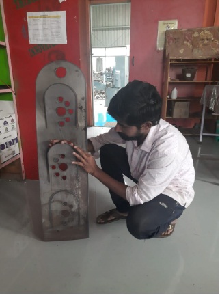
Then For making useful magzine holder I have done some processes on it like Bending, finishing and painting.and Finally it is a useful magzine holder we can use it our FABLAB at vigyan ashram.
 |
 |
 |  |
 |  |
Then next part is to explore the embroidery work for Wild Week.
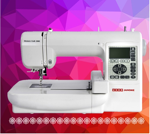
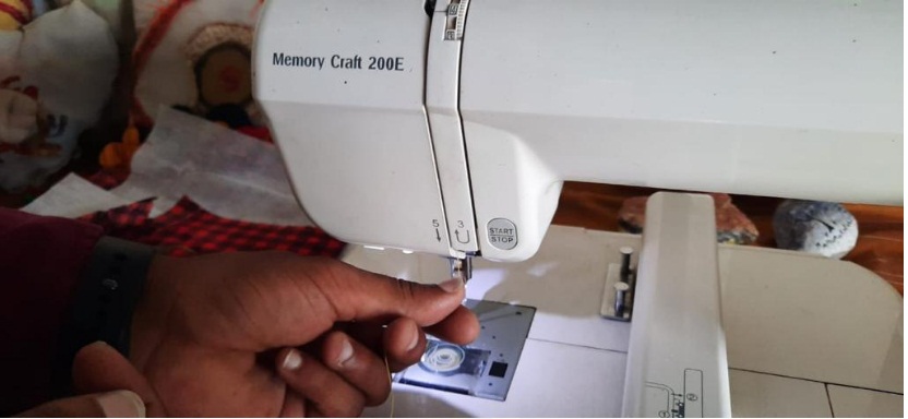
About USHA Janome Memory Craft Sewing Machine.
Often called the computerized dream machines, the Memory Craft series of specialized and professional computerized sewing and embroidery machine is for those wanting to work across garments, quilting, and home decor etc. While its wi-fi and iPad compatibility help you expand your creativity, its speed and precision add that critical edge needed for advanced sewing. Sewing speeds of 1,000 stitches per minute, special features designed for the quilter, including specialty stitches and an advanced feed mechanism enable those who want do more and do better.For user manual click here.
Memory Craft 200E with Digitizer Jr.
A computerised embroidery machine, the Memory Craft 200 E is ideal for embroidering up to 140 X 140 mm designs. Multiple font sizes are available for each font to design monograms and a USB Port helps import customized designs. Along with this the free Digitizer Jr V5 software allows one to edit existing designs and making select custom designs. 73 built in designs and a backlit LCD screen help scale up one’s creativity.
Features:-
Single needle computerized embroidery machine.
73 Built in embroidery designs.
USB Port for importing Customized Designs.
Built in Memory for storing Customized designs.
Backlit LCD screen
Digitizer Jr –
Janome’s Digitizer Jr software gives you the freedom to express yourself in stitches, monograms and more.
It has an auto digitizing system that converts any image into a design you can sew.
Digitizer Jr has a three-in-one application – Easy Create, Easy Import and Easy Edit
Easy Create – Use the Digitizer Jr to create your own designs with your PC and then embroider them on your Usha Janome Memory Craft.
Easy Import – With the auto register facility you can turn your BMP ,WMF , JPG image into an embroidery pattern (.JEF format) with one click of your mouse.
asy Edit- The automatic layout feature makes it easy to mirror designs, add borders, add Arc Layout and to flip and rotate the design.
Techncal Specifications.
Single needle computerized embroidery machine.
Backlit LCD Screen :: Yes
Built in Embroidery Designs :: 73
Built in Monogramming Fonts :: 3
Design Resizing Capability :: Yes
Design Rotation Capability :: Yes
Embroidery Sewing Speed(spm) :: 650 spm (Stitches Per Minute)
Maximum Embroidery Area ::140mm X 140mm
Needle Threading :: Yes
Optional Hoops :: 1
Standard Hoops :: 1
Thread cutter :: Manual
USB Port :: Yes
2D Desinging in Inkscape software
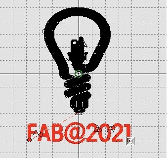
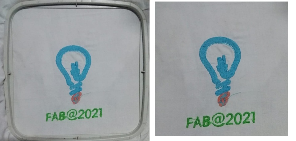
For this work I tried to designed the logo that indicate the eletrical bulb as I am eletrical Engineer to learn this Embroidery machine and how its work I tried to drwa this simple designed , This designed I took from Google and edit this in Inkscape software.
This is I have taken some shots during designed
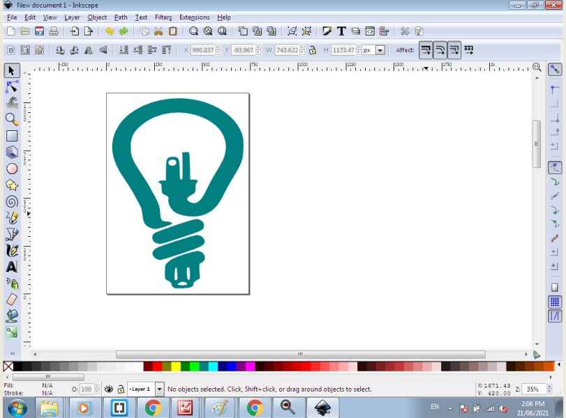
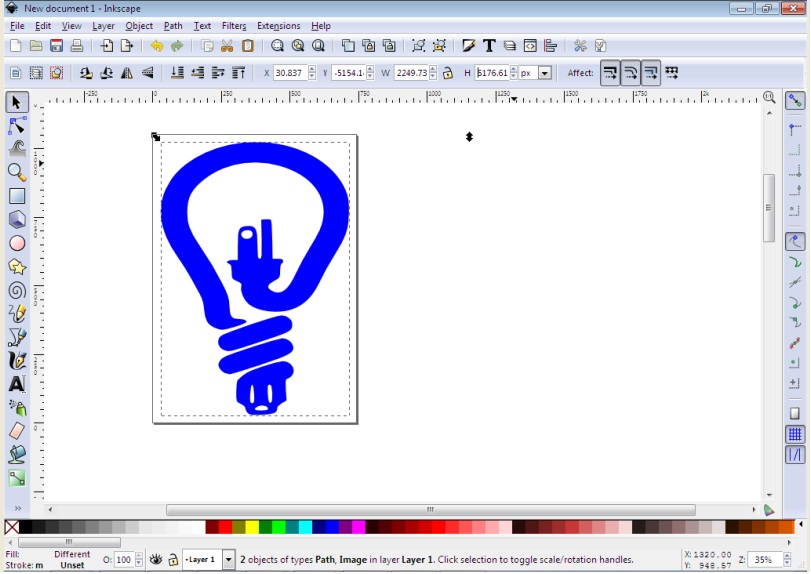
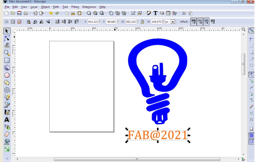
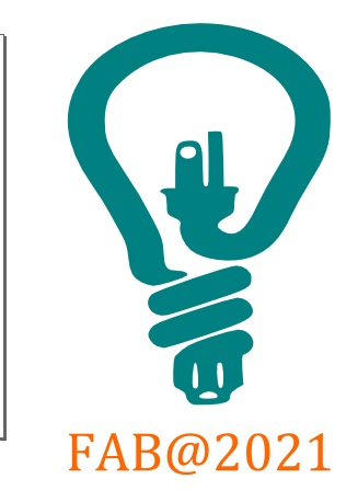
We can select the colour in inkscape as per our choice.
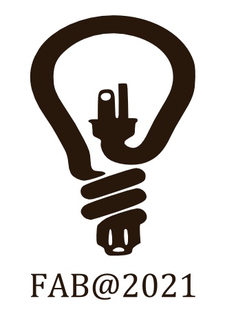
Save this final in .svg format ,digitizer software need the .svg file.
Then I have proceed this design for Digitizer junior Version-5
About Digitizer Junior Version 5
Enter the world of embroidery design with DigitizerJR! Janome's DigitizerJR software gives you the freedom to express yourself and to show off your creativity.
Powerful, easy to use interface with large icons.
Multi-hoop layout with Easy Layout
Automatic adjustment for different fabrics
Use Lettering Create monogram designs
Embroidery lettering editing
Built-in fonts
Satin and Weave fills
Single and Triple line stitches
ealistic view of designs with Visualizer
Split design capability for MA/Giga Hoops
Machine connectivity via USB cable
Supported embroidery files: JAN, JEF, JEF+, SEW, EMD, EMX, JMT, PES, PEC, HUS, VIP, VP3, EXP, PCS, PCM, CSD, XXX, DST
Supported graphics files: BMP, JPG, WMF, EMF
Use Digitizer J5 for G-code
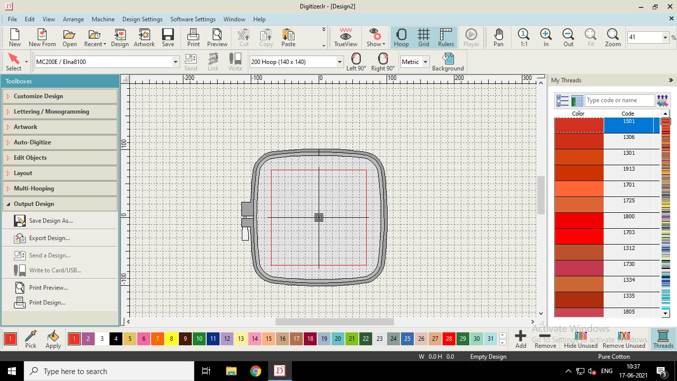
The opening window of Digitizer software is shown in the image.
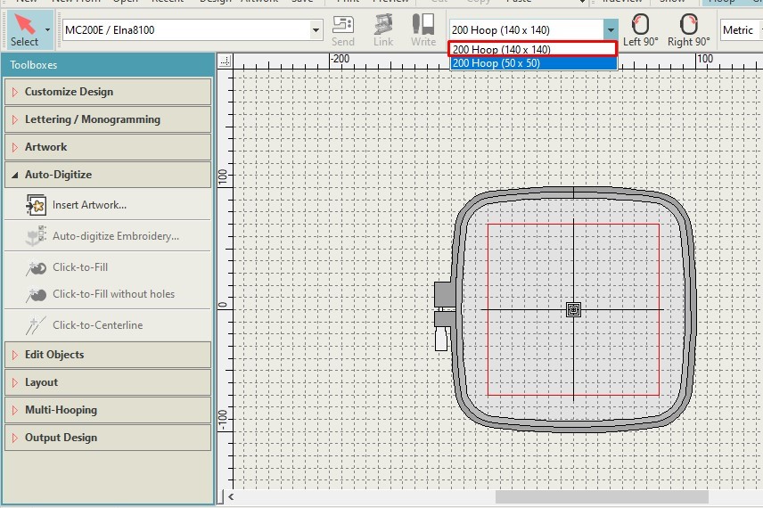
Then Select the hoop of required size.
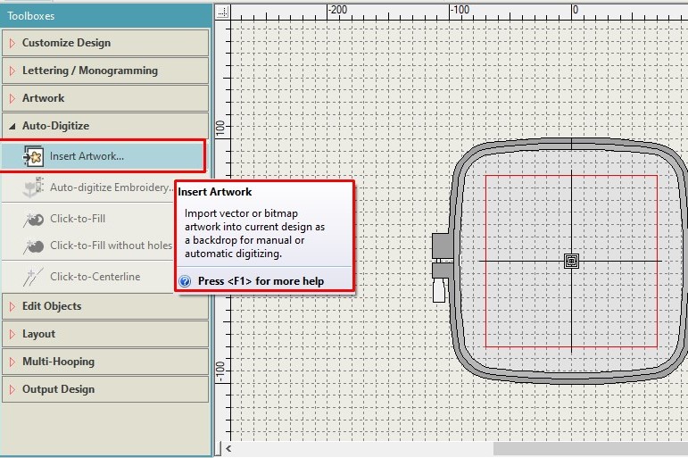
Then we need to select “Insert Artwork” and select the required image.
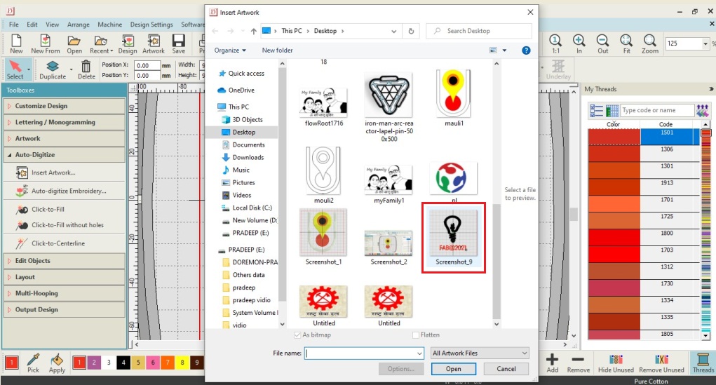
Then we need to Adjust the inserted image according to the red frame given in the hoop.
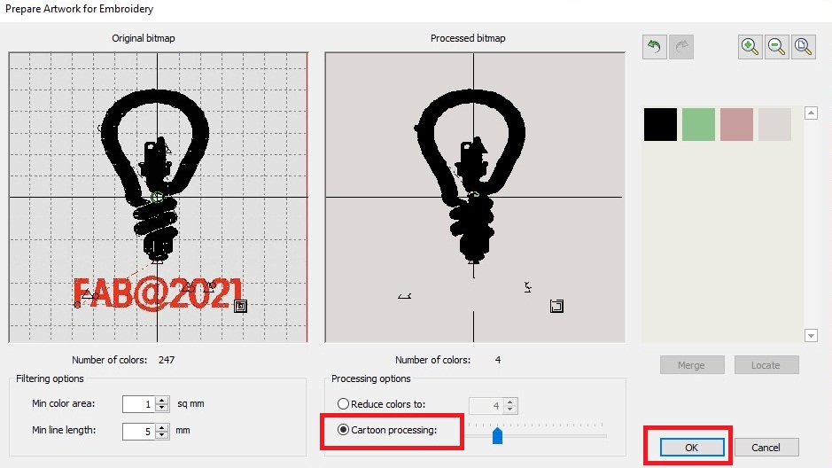
Opening the window of “Prepare Artwork for Embroidery” click on “Cartoon processing” and adjust the bitmapping properly. Click on ok.
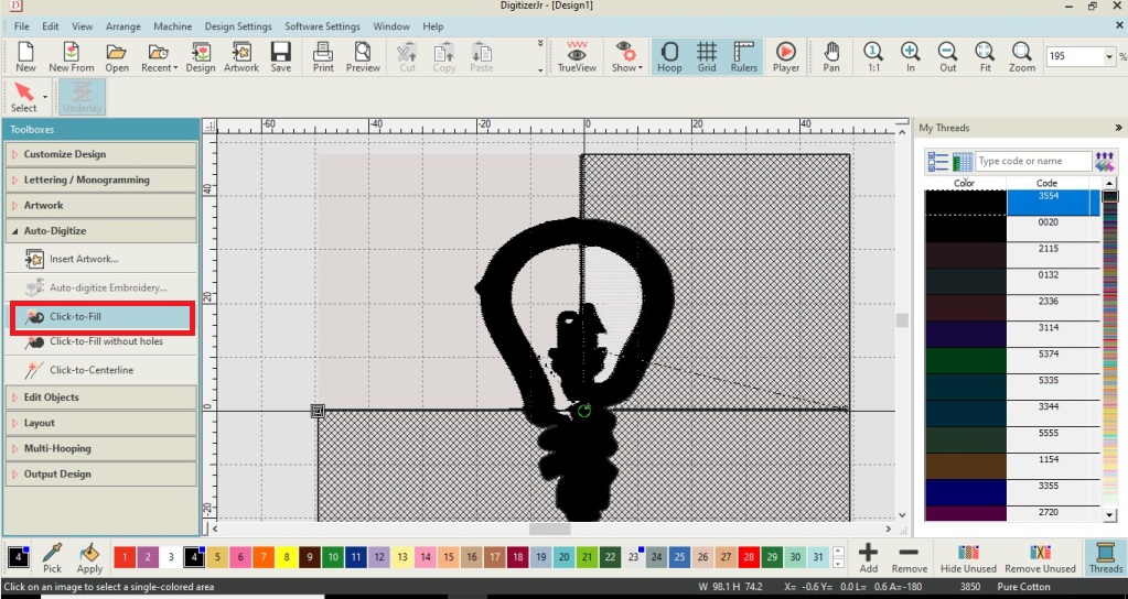
Now we can select the different parts of an object for filling the color threads as per our choice and need. Double click on the object, it appears netted black. Select the color from the bottom list and click on apply.
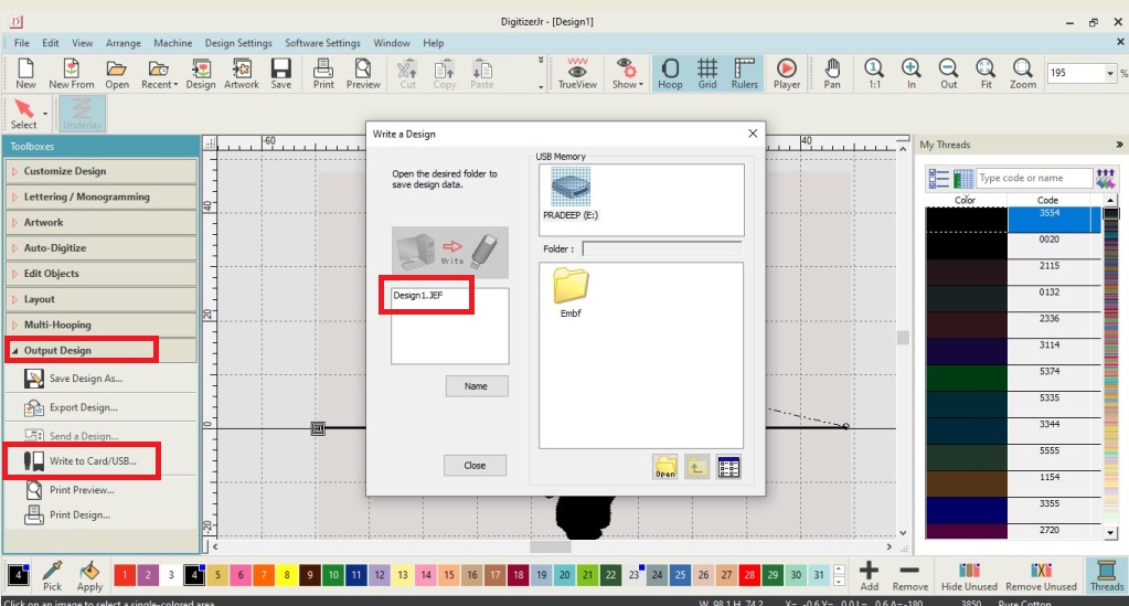
Now goto the “Output Design” and save the file in the USB drive having extension .EMB.
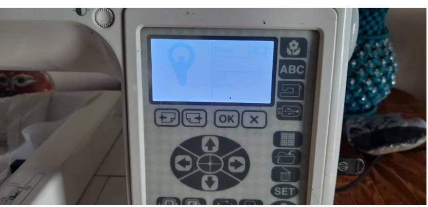
Now applying the USB drive to the sewing machine. On the machine panel goto the USB derive select the file for Embroidery.
Then,Fill the bobbin properly and apply the required thread to the sewing machine as per manual.
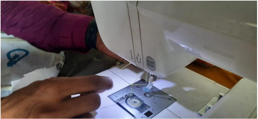
I have used my handkerchief for embroidery work.Properly arrange the cloth in the hoop and applied it to machine as shown below.
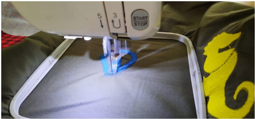
After some time embroidery work completed by the machine.
Learning Outcomes:-
1. This Week is about to explore about as per interest using digital fabrication.
2. For this week I have Understood the various featurs of Plasma cuttern CNC machine.
3. Learnt about how can cut the metal sheet using this machine.
4. I have learnt about which problems we need to face during using plasma machine.
5. I have learnt about the Kerf calculations and various parameter for cutting the 2D desinged in plasma cutter machine.
6. Understood the Used the Digitizer software for creating embroidery work tool path.
7. Understood the used the digital sewing machine for embroidery work.
DOWNLOAD's
Download my original file here