
Assignment#10: Output Devices
This assignment is about documenting what I learned in Output Devices that includes types of output devices, their working principles and how to connect them to different microcontroller boards including the one that I made for this week. I have documented how I designed my board cosidering certain output devices I wanted to connect to the board. Through this assignment, I also started to design board for my final project. My purpose is also to use this board to connect the output devices I am going to use in my project. I was able to complete complete one board specifically for this assignment and programmed it to run the output devices. I could complete the design, milling, soldering my final project board in this week itself. However, I could not complete programming that board. I am also documenting what went well, what went wrong, how I would do things differently in next assignment and my learning outcomes.
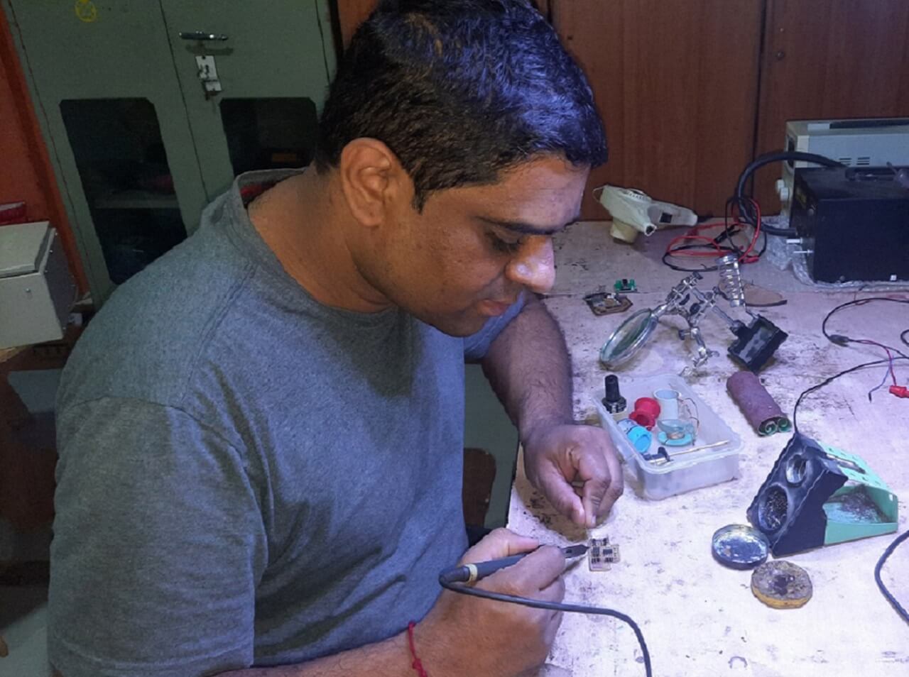
My Hero shots for this week
 |
 |
 |
 |
My Hero videos for this week
1. Using Relay as an Output device on my board
2. Using DC toy motor as an Output device on my board
3. Using RGB LED module as an Output device on my board
4. Using active buzzer as an Output device on my board
Click here to go back to the top
Basics of Output Devices
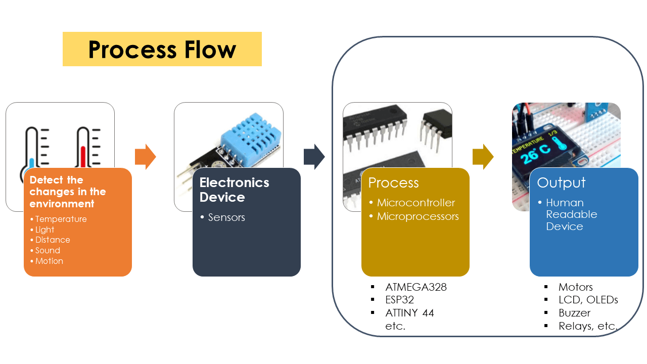
An output device is any piece of hardware item, which utilizes whatever data and commands from a micro controller or microprocessor in order to perform certain tasks. This leads to the results of data processing carried out by an information processing system (such as a microcontroller), which converts the electronically generated information into human-undestandable form. They receive a data or a signal from another device to actuate itself in any sort of way that human can sense either by seeing, feeling, hearing, smelling or may be tasting.
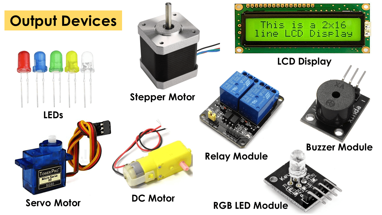
The basic examples of output devices that we use in our daily life are TV, fan, computer screen, screen of mobile phone, motors, etc. Typical examples of output devices that we use with micro-controllers are, stepper motor, servo motor, DC motor, LCD display, OLED display, LEDs, relay, buzzer, speaker,etc. Output device can exist with or without sensor like input devices. I can operate the output device through a sensor or from the signal received from a microcontroller.
References: Reference#1, Reference#2, Reference#3
 |
 |
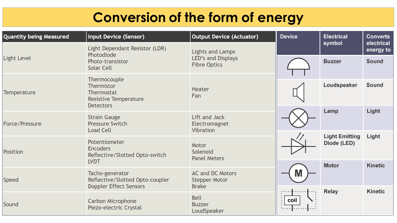
Output devices in electronic systems transform electrical energy into another type of energy, such as light, sound or kinetic energy . Common output devices and their associated energy changes are shown in the table below.
 |
Before I write what I did in this week of output devices, I am going to write about some of the output devices as below and also write how I first connected them to arduino board before I connected them to the board I designed for this week.
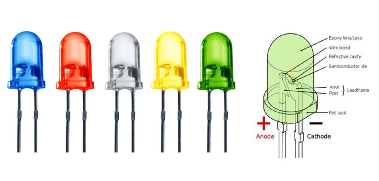
1. Light-Emitting Diode (LED)
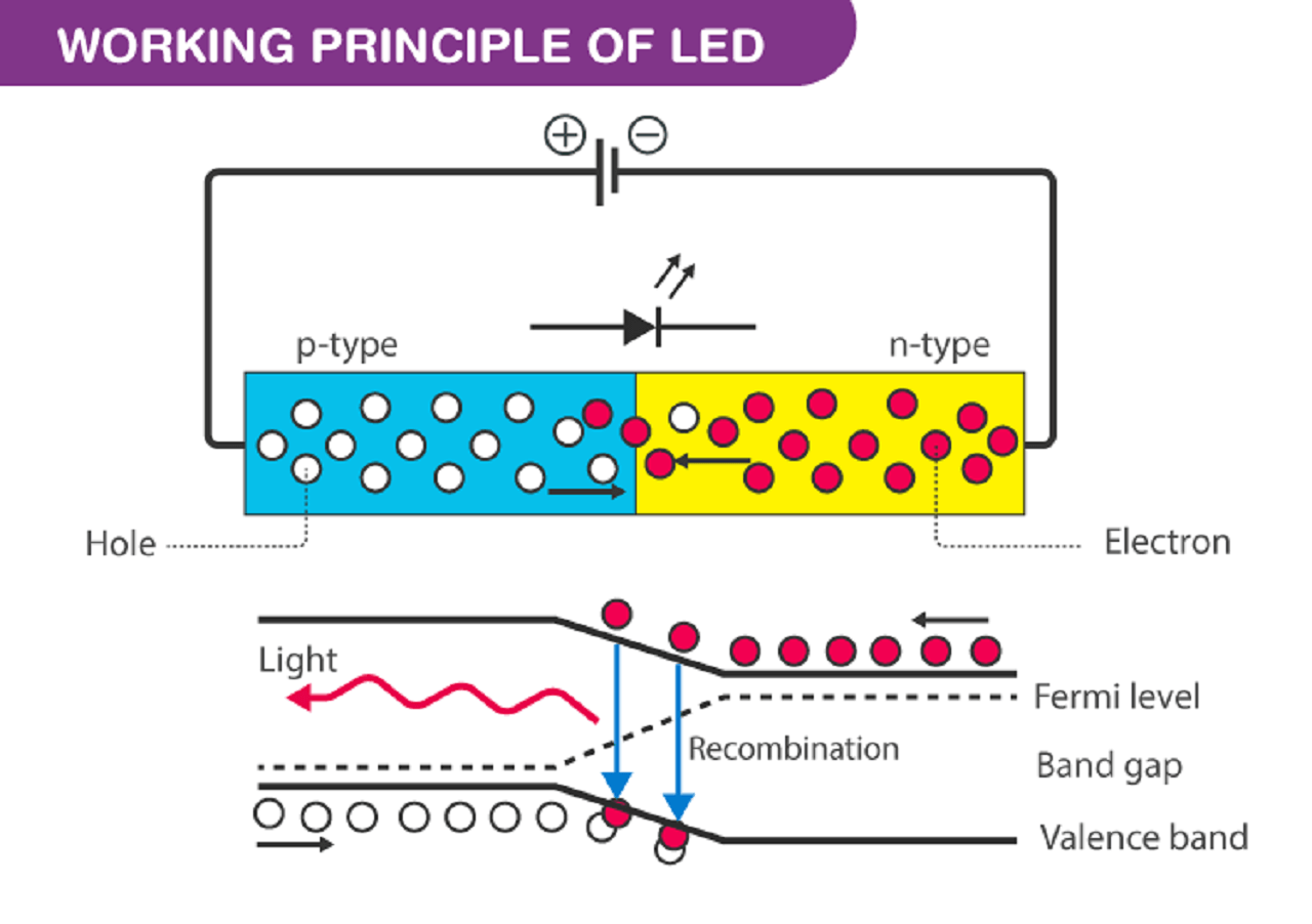
Unlike filament lamps, where electrical energy must be converted into heat before light can be produced, Light Emitting Diodes (LEDs) are able to transform electrical energy directly into light energy. LED is a semiconductor device that emits infrared or visible light when charged with an electric current. Since the LED is a diode, it will only light up when current is in the correct (conducting) direction. This means that an LED will pass current in its forward direction but block the flow of current in the reverse direction. Light emitting diodes are made from a very thin layer of fairly heavily doped semiconductor material and depending on the semiconductor material used and the amount of doping, when forward biased an LED will emit a coloured light at a particular spectral wavelength.
How LEDs work: When the diode is forward biased, the minority electrons are sent from p to n while the minority holes are sent from n to p. At the junction boundary, the concentration of minority carriers increases. The excess minority carriers at the junction recombine with the majority charges carriers. The energy is released in the form of photons on recombination. In standard diodes, the energy is released in the form of heat. But in light-emitting diodes, the energy is released in the form of photons. We call this phenomenon electroluminescence. Electroluminescence is an optical phenomenon, and electrical phenomenon where a material emits light in response to an electric current passed through it. As the forward voltage increases, the intensity of the light increases and reaches a maximum. References.
In some circuits the current in an LED circuit must be limited to avoid damaging the LED. A series resistor is used to reduce current in the circuit and ensure the LED is not damaged. References
 |
 |
2. DC Motor
A DC motor is any of a class of rotary electrical motors that converts direct current (DC) electrical energy into mechanical energy. The most common types rely on the forces produced by magnetic fields. Nearly all types of DC motors have some internal mechanism, either electromechanical or electronic, to periodically change the direction of current in part of the motor.
DC motors were the first form of motor widely used, as they could be powered from existing direct-current lighting power distribution systems. A DC motor's speed can be controlled over a wide range, using either a variable supply voltage or by changing the strength of current in its field windings. Small DC motors are used in tools, toys, and appliances. The universal motor can operate on direct current but is a lightweight brushed motor used for portable power tools and appliances. Larger DC motors are currently used in propulsion of electric vehicles, elevator and hoists, and in drives for steel rolling mills. The advent of power electronics has made replacement of DC motors with AC motors possible in many applications. Reference.
Specifications of DC Motor:
- Standard 130 Type DC motor
- Operating Voltage: 4.5V to 9V
- Recommended/Rated Voltage: 6V
- Current at No load: 70mA (max)
- No-load Speed: 9000 rpm
- Loaded current: 250mA (approx)
- Rated Load: 10g*cm
References: Click here
I connected DC motor to arduino board through L293D motor driver H bridge as shown below
Reference Tutorial
3. Stepper Motor
A stepper motor, also known as step motor or stepping motor, is a brushless DC electric motor that divides a full rotation into a number of equal steps. The motor's position can be commanded to move and hold at one of these steps without any position sensor for feedback (an open-loop controller), as long as the motor is correctly sized to the application in respect to torque and speed.
Brushed DC motors rotate continuously when DC voltage is applied to their terminals. The stepper motor is known for its property of converting a train of input pulses (typically square waves) into a precisely defined increment in the shaft's rotational position. Each pulse rotates the shaft through a fixed angle.
Stepper motors effectively have multiple "toothed" electromagnets arranged as a stator around a central rotor, a gear-shaped piece of iron. The electromagnets are energized by an external driver circuit or a micro controller. To make the motor shaft turn, first, one electromagnet is given power, which magnetically attracts the gear's teeth. When the gear's teeth are aligned to the first electromagnet, they are slightly offset from the next electromagnet. This means that when the next electromagnet is turned on and the first is turned off, the gear rotates slightly to align with the next one. From there the process is repeated. Each of those rotations is called a "step", with an integer number of steps making a full rotation. In that way, the motor can be turned by a precise angle. Reference.
Stepper Motor Drivers: Stepper motor driver is an actuator which can transform pulse signal into angular displacement signal, Stepper drivers drive stepper motors to rotate at an angle called step angle in the set direction when receiving a pulse signal. The motor speed is up to the pulse frequency given from the controller, and the displacement is decided on the pulse quantity given from the controller. Stepper system consists of a stepper motor and a stepper driver. Performance of a stepper system is not only up to the motor, but also depends on the stepper driver. Reference.
Specifications of NEMA 17 Stepper Motor:
- Rated Voltage: 12V DC
- Current: 1.2A at 4V
- Step Angle: 1.8 deg.
- No. of Phases: 4
- Motor Length: 1.54 inches
- 4-wire, 8 inch lead
- 200 steps per revolution, 1.8 degrees
- Operating Temperature: -10 to 40 Deg C
- Unipolar Holding Torque: 22.2 oz-in
References: Click here
I connected stepper motor to arduino board through two different stepper drivers- A4988, A3967 and ULN2003 as shown below. Reference Tutorial for A4988 Driver.
Reference Tutorial for A3967 Driver.
Reference Tutorial
4. Servo Motor
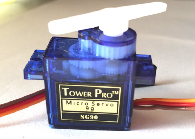
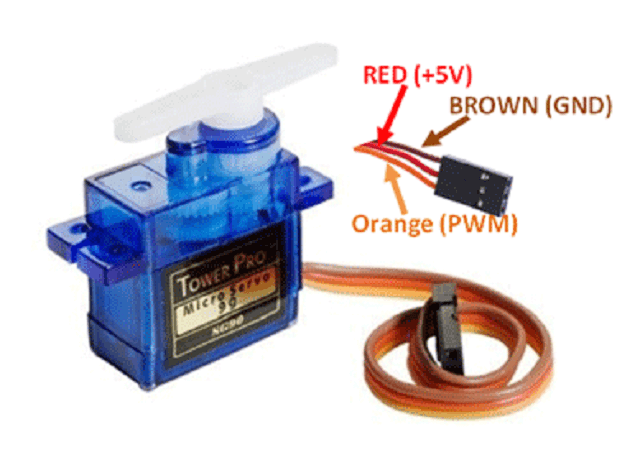
A servomotor (or servo motor) is a rotary actuator or linear actuator that allows for precise control of angular or linear position, velocity and acceleration. It consists of a suitable motor coupled to a sensor for position feedback. It also requires a relatively sophisticated controller, often a dedicated module designed specifically for use with servomotors.
Servomotors are not a specific class of motor, although the term servomotor is often used to refer to a motor suitable for use in a closed-loop control system. Servomotors are used in applications such as robotics, CNC machinery, and automated manufacturing.
A servomotor is a closed-loop servomechanism that uses position feedback to control its motion and final position. The input to its control is a signal (either analogue or digital) representing the position commanded for the output shaft. The motor is paired with some type of position encoder to provide position and speed feedback. In the simplest case, only the position is measured. The measured position of the output is compared to the command position, the external input to the controller. If the output position differs from that required, an error signal is generated which then causes the motor to rotate in either direction, as needed to bring the output shaft to the appropriate position. As the positions approach, the error signal reduces to zero and the motor stops. Reference.
 |
 |
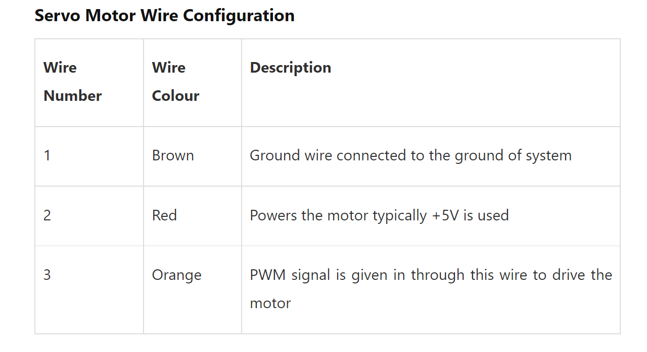 |
Specifications of SG-90 Servo Motor:
- Operating Voltage is +5V typically
- Torque: 2.5kg/cm
- Operating speed is 0.1s/60 deg
- Gear Type: Plastic
- Rotation : 0-180 Deg
- 4-wire, 8 inch lead
- Weight of motor : 9gm
- Package includes gear horns and screws
References: Click here
I connected servo motor to arduino board as shown below.
5. LCD Display
An electronic device that is used to display data and the message is known as LCD 16x2. As the name suggests, it includes 16 Columns and 2 Rows so it can display 32 characters (16x2=32) in total & every character will be made with 5x8 (40) Pixel Dots. So the total pixels within this LCD can be calculated as 32 x 40 otherwise 1280 pixels.
16 X2 displays mostly depend on multi-segment LEDs. There are different types of displays available in the market with different combinations such as 8x2, 8x1, 16x1, and 10x2, however, the LCD 16x2 is broadly used in devices, DIY circuits, electronic projects due to less cost, programmable friendly and simple to access.
Specifications of 16x2 LCD Display:
- The operating voltage of this display ranges from 4.7V to 5.3V
- The display bezel is 72 x 25mm
- The operating current is 1mA without a backlight
- PCB size of the module is 80L x 36W x 10H mm
- HD47780 controller
- LED color for backlight is green or blue
- Number of columns - 16
- Number of rows - 2
- Number of LCD pins - 16
- Characters - 32
- It works in 4-bit and 8-bit modes
- Pixel box of each character is 5x8 pixel
- Font size of character is 0.125Width x 0.200height
Reference.
I connected 16x2 LCD display to arduino board as shown below. In the video below, I have shown two different programs, one for static text display and another for scrolling display.
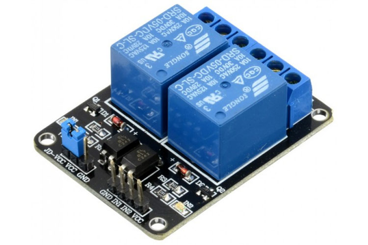
6. Relay
The dual channel relay module is similar to a single-channel relay module with some extra features like optical isolation. The dual channel relay module is used to switch mains powered loads from the pins of a microcontroller. Reference for dual channel relay module datasheet.
 |
 |
 |
Images Credits: Reference
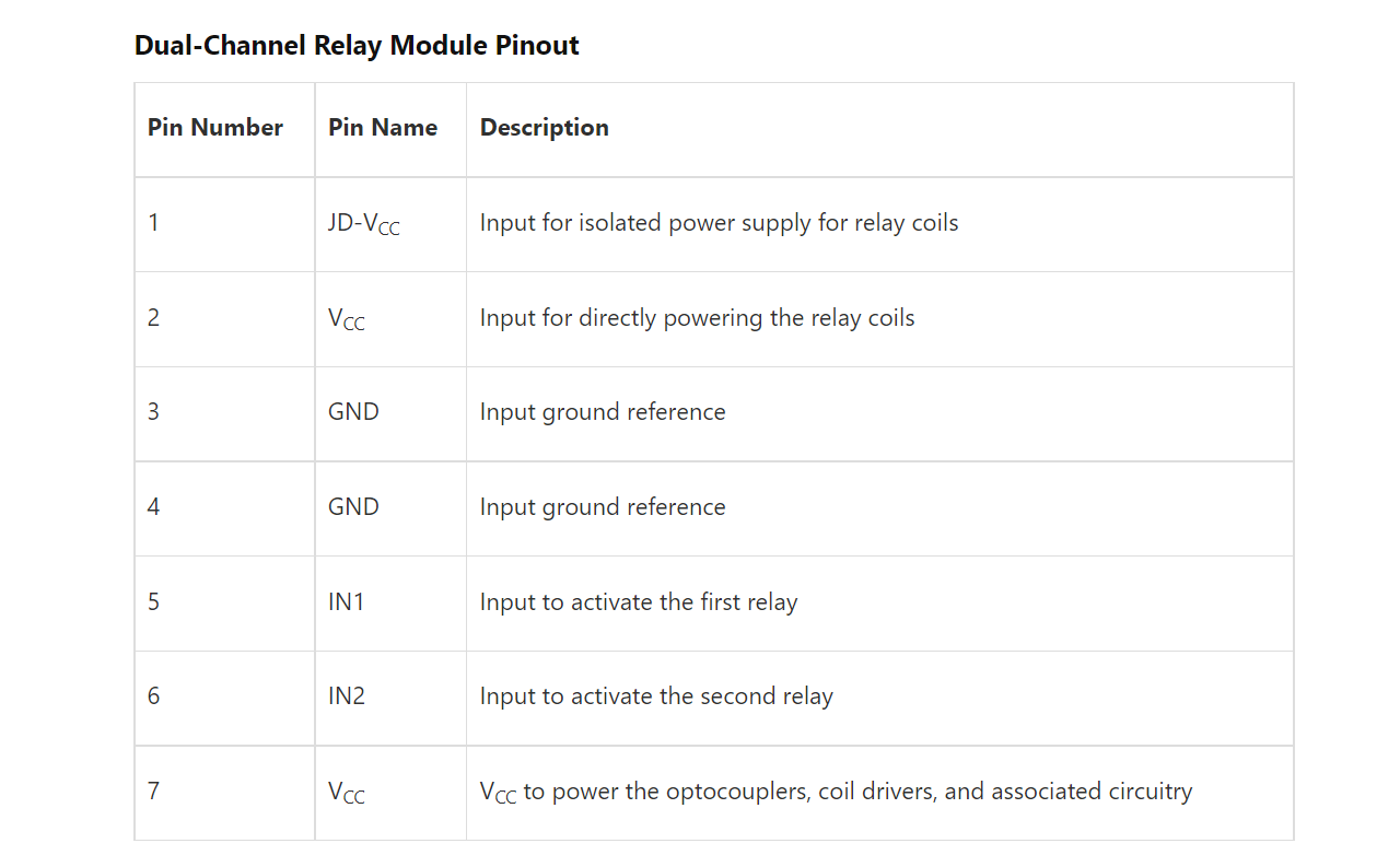
Specifications of Dual-Channel Relay Module:
- Supply voltage - 3.75V to 6V
- Trigger current - 5mA
- Current when relay is active - ~70mA (single), ~140mA (both)
- Relay maximum contact voltage - 250VAC, 30VDC
- Relay maximum current - 10A
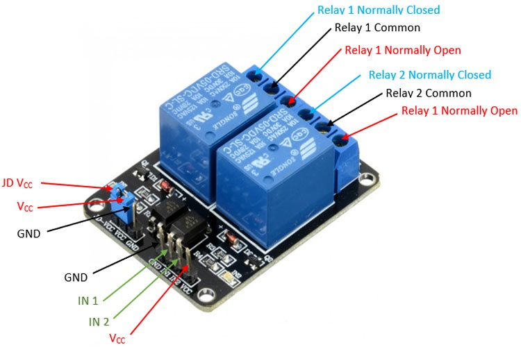
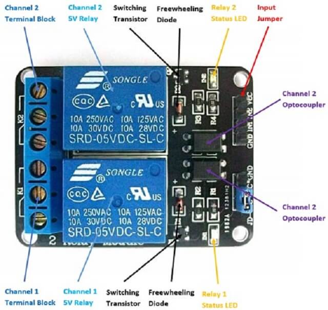
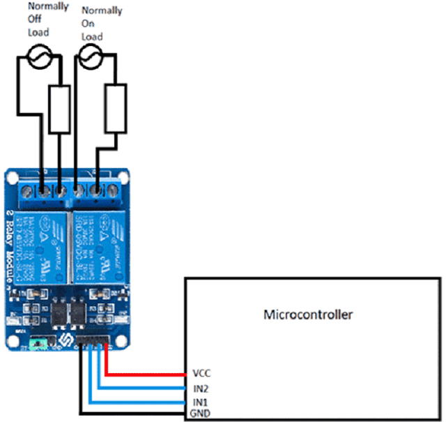
How to use Dual-Channel Relay Module:
Dual channel relay module is used to switch the mains powered loads from the pins of a microcontroller. As there are two channels on same board, two separate loads can be connected and powered. The loads can be connected as shown below. In the diagram above, relay on the left side (channel 1) is connected in a regular way with load and source connected between common and normally open, so as the relay is activated, the load is powered. On the right-side channel (channel 2), load and source are connected between common and normally closed that means the load is powered by default till the relay is activated.
 |
 |
Reference.
I connected a two channel relay to an AC bulb through arduino board as shown below.
Click here to go back to the top
Group Assignment Brief
This assignment is about documenting what we learned in Output Devices week that includes understanding different output devices and measure the power consumption of an output device on one of the boards we made as a part of individual assignment for this week.
Objectives of the Group Assignment:
- Measure the power consumption of an output device
Output Devices that we measured the power consumption of:
- DC motor
- RGB LED
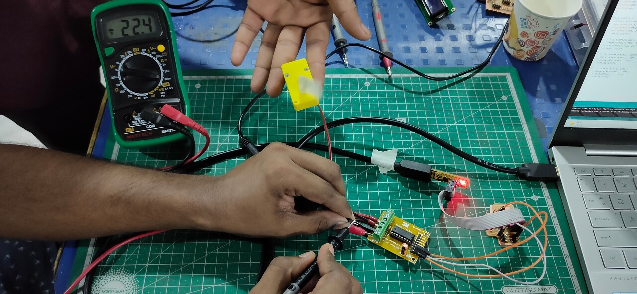
1. We connected DC motor to the output devices board and ran the motor after programming the board through arduino IDE. First we measured current in series and then we measured current in series and voltage across parallel connection as shown below.
 |
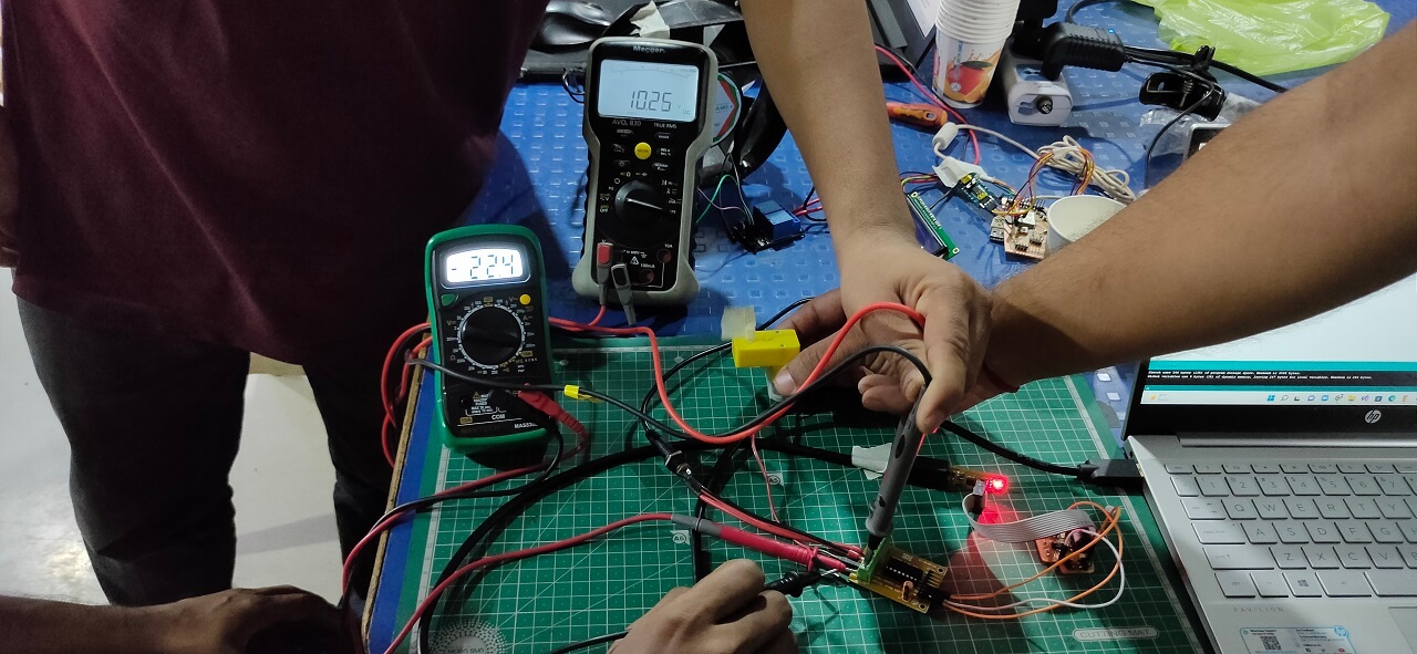 |
Power consumption of a DC motor: The measured voltage (V) for the DC motor was 10.25 Volts and the value of current required (I) was varying. However, the one, which was most consistent was 22.4 mA. So the power consumption of a DC toy motor= P= V x I = 10.25 x 0.0224 A = 0.2296 Watts.
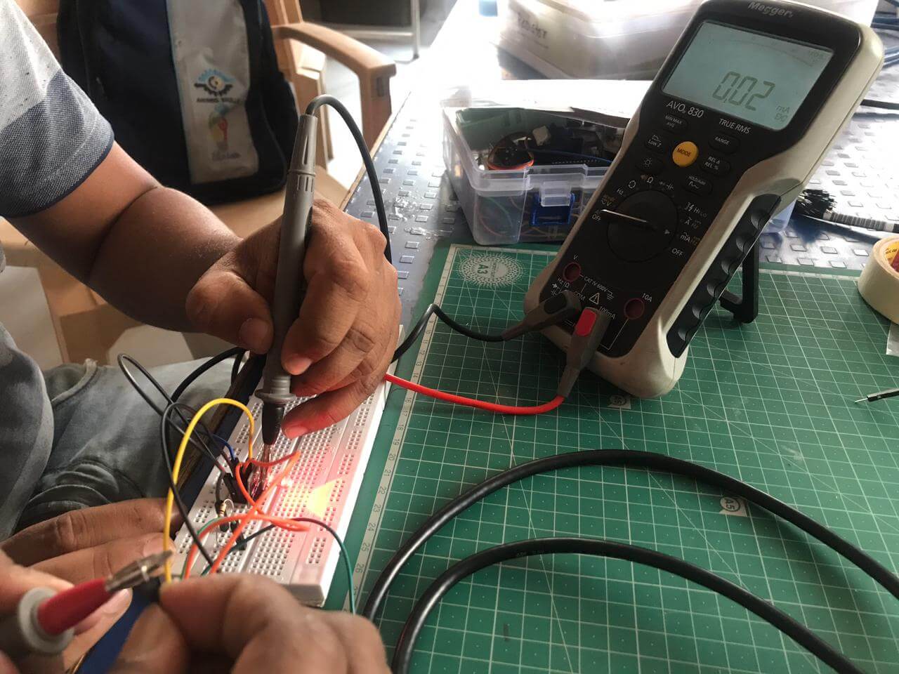
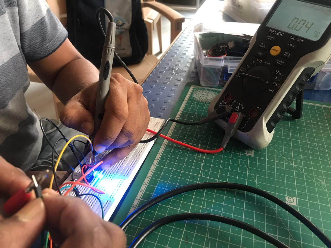
2. In second case, we connected RGB LED module to the output devices board and blinked each LED (Red, Green and Blue) separately after programming the board through arduino IDE. Also measured the current by attaching the resistor of 80K in series with the help of Megger make multimeter as shown below.
 |
 |
 |
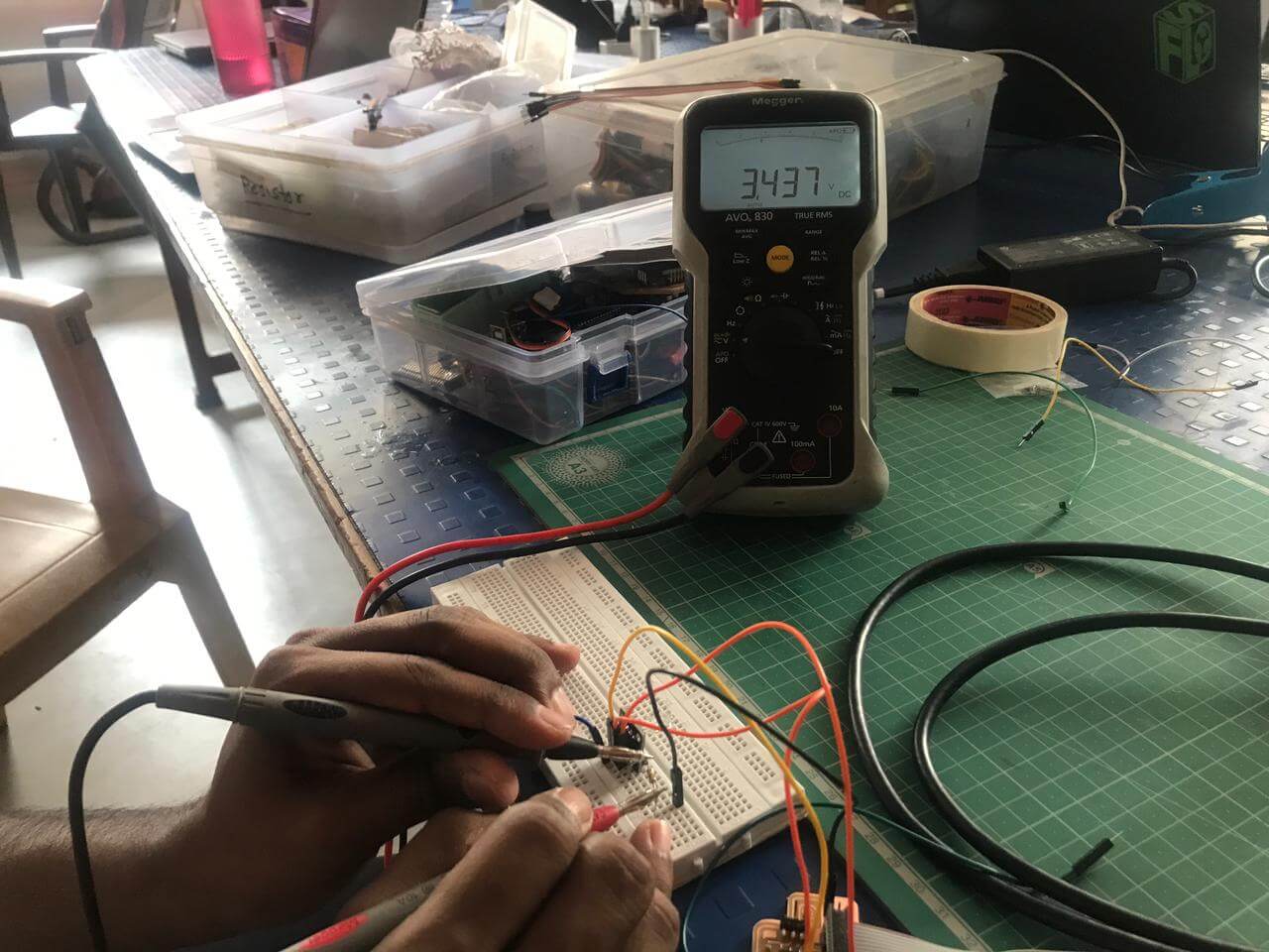 |
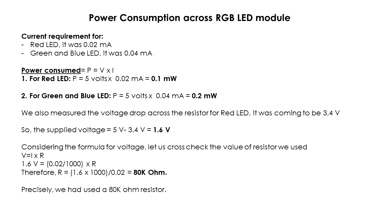
Power consumption of RGB LED: The operating voltage (V) for RGB LED was 5 Volts and the value of current (I) was different for Red, Green and Blue LED. For Red LED, it was 0.02 mA, for Green and Blue LED, it was 0.04 mA. Following are our calculations of power consumption of RGB LED.
 |
Click here to read more about our Group Assignment.
Click here to go back to the top
Individual Assignment
Objectives of Individual Assignment:
- Add an output device to a microcontroller board you have designed
- Program it to do something
 |
 |
 |
 |
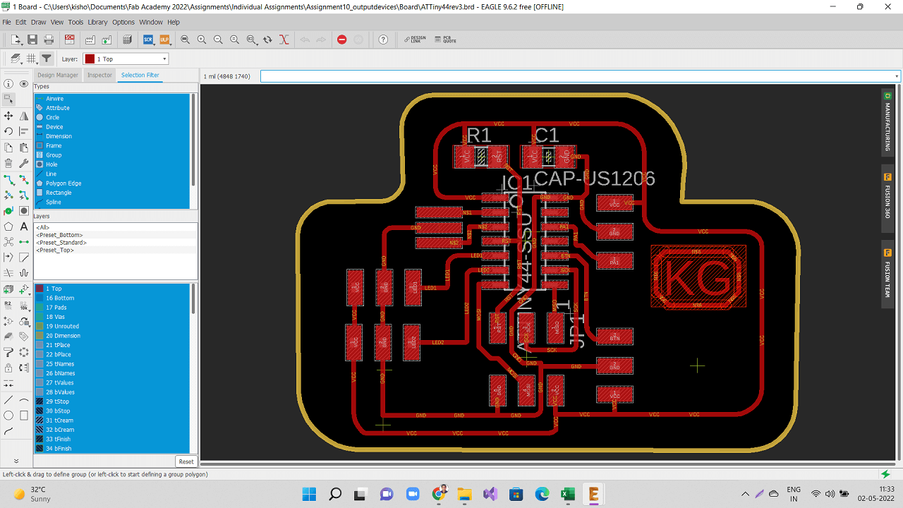
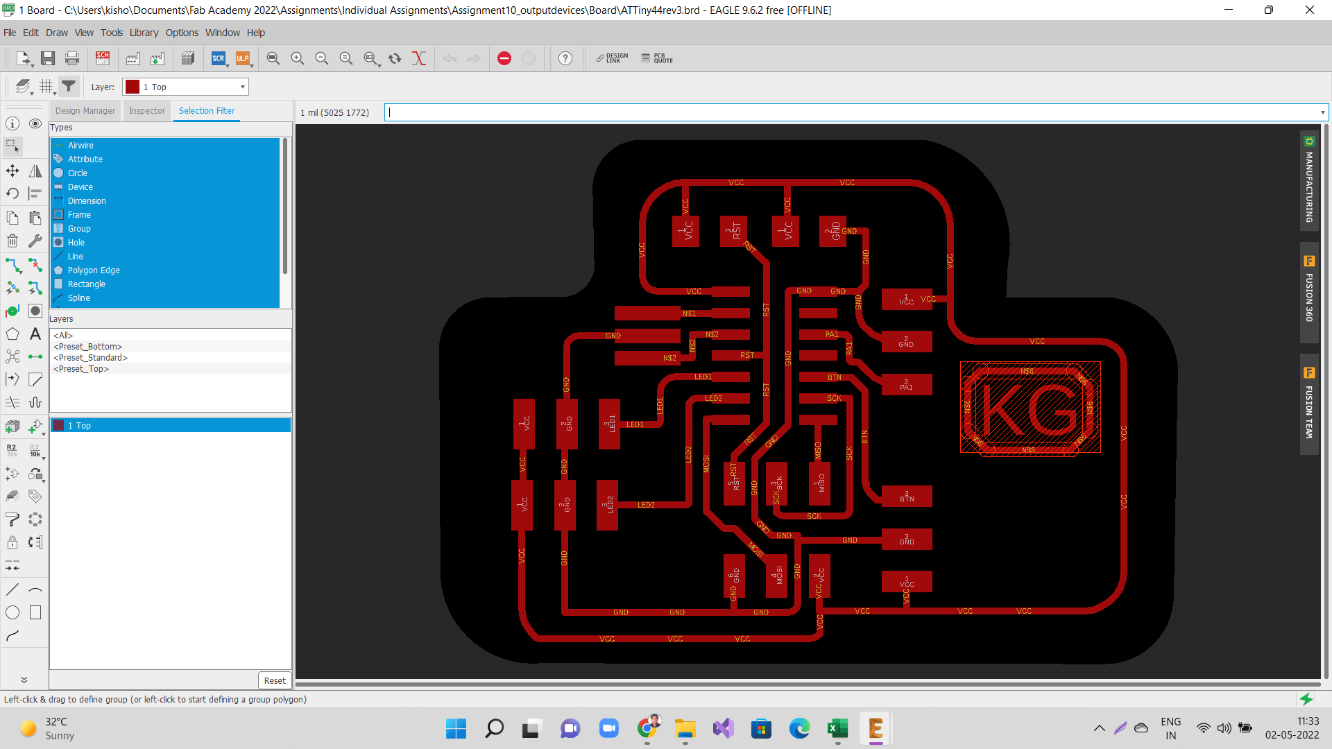
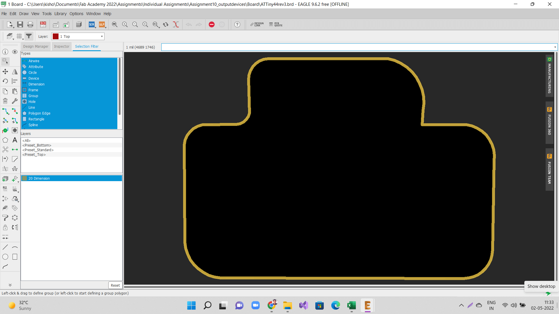
1. Designing a board for output devices
As I mentioned earlier, this week I designed, milled and stuffed two boards, one for my final project and one just for this assignment. I programmed the output device board and made an attempt to program my final project board. However, I could not program it because of some issues that I will explain in subsequent sections below.
 |
|
 |
 |
 |
 |
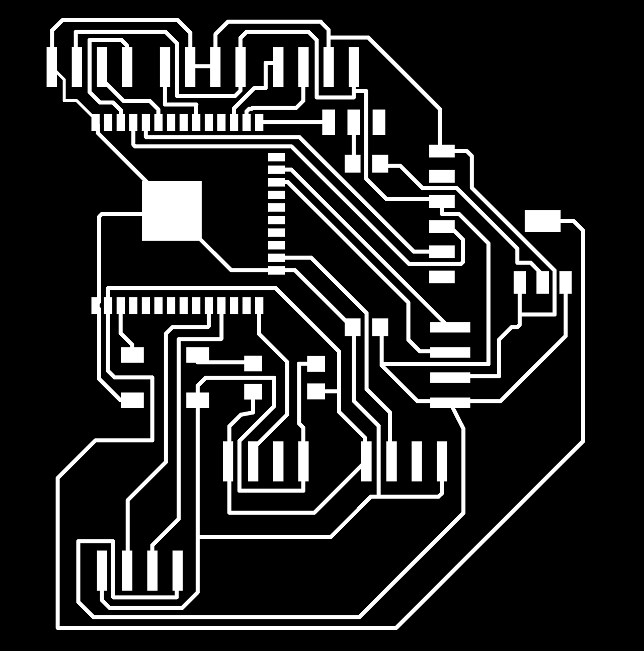
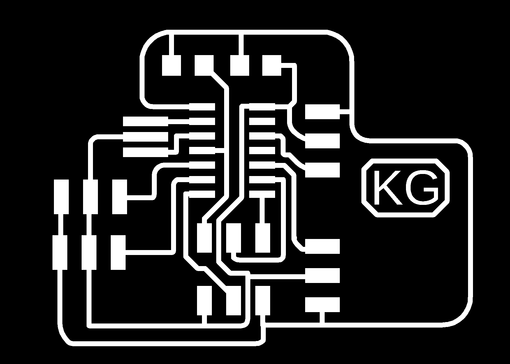
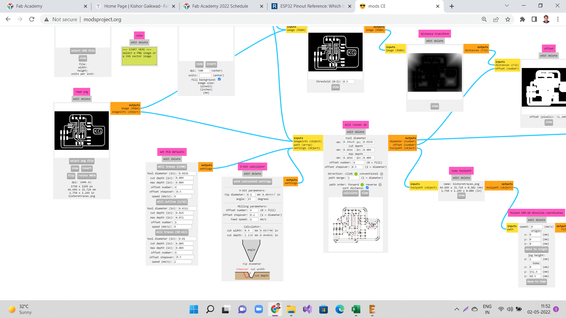
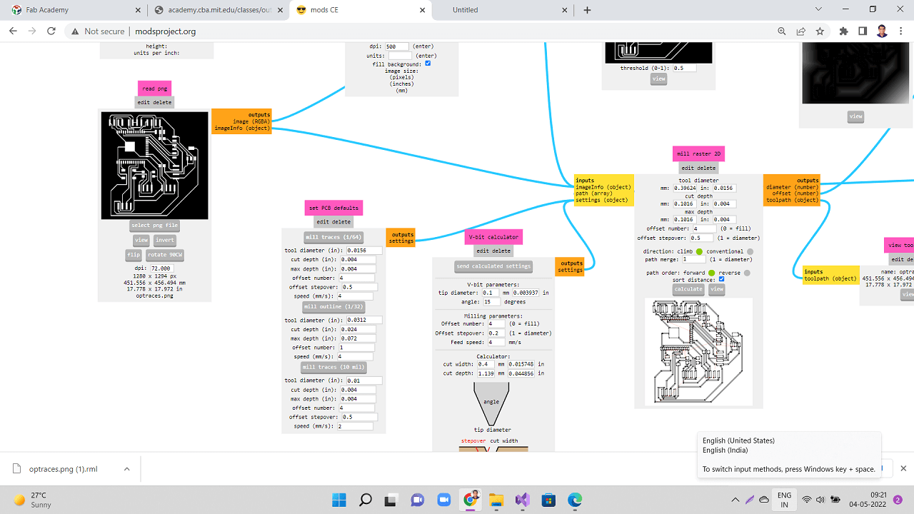
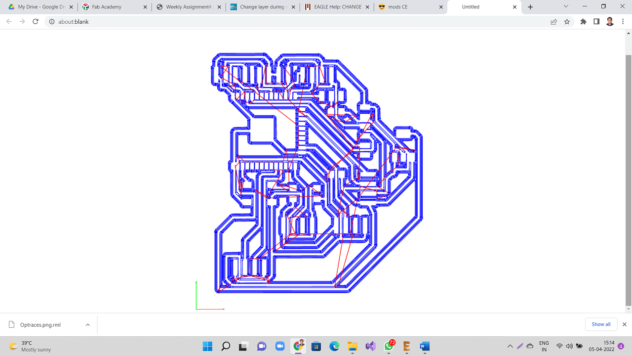
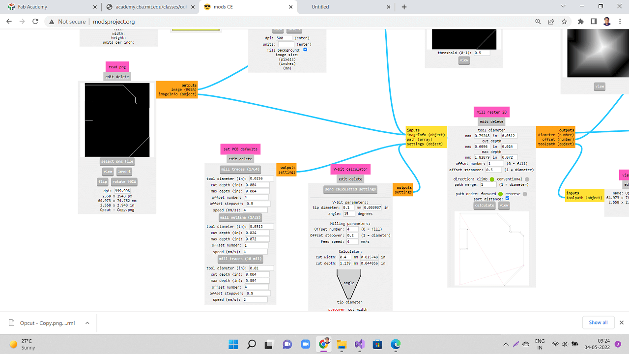
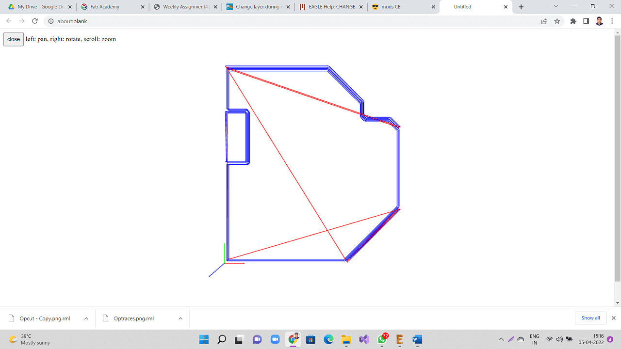
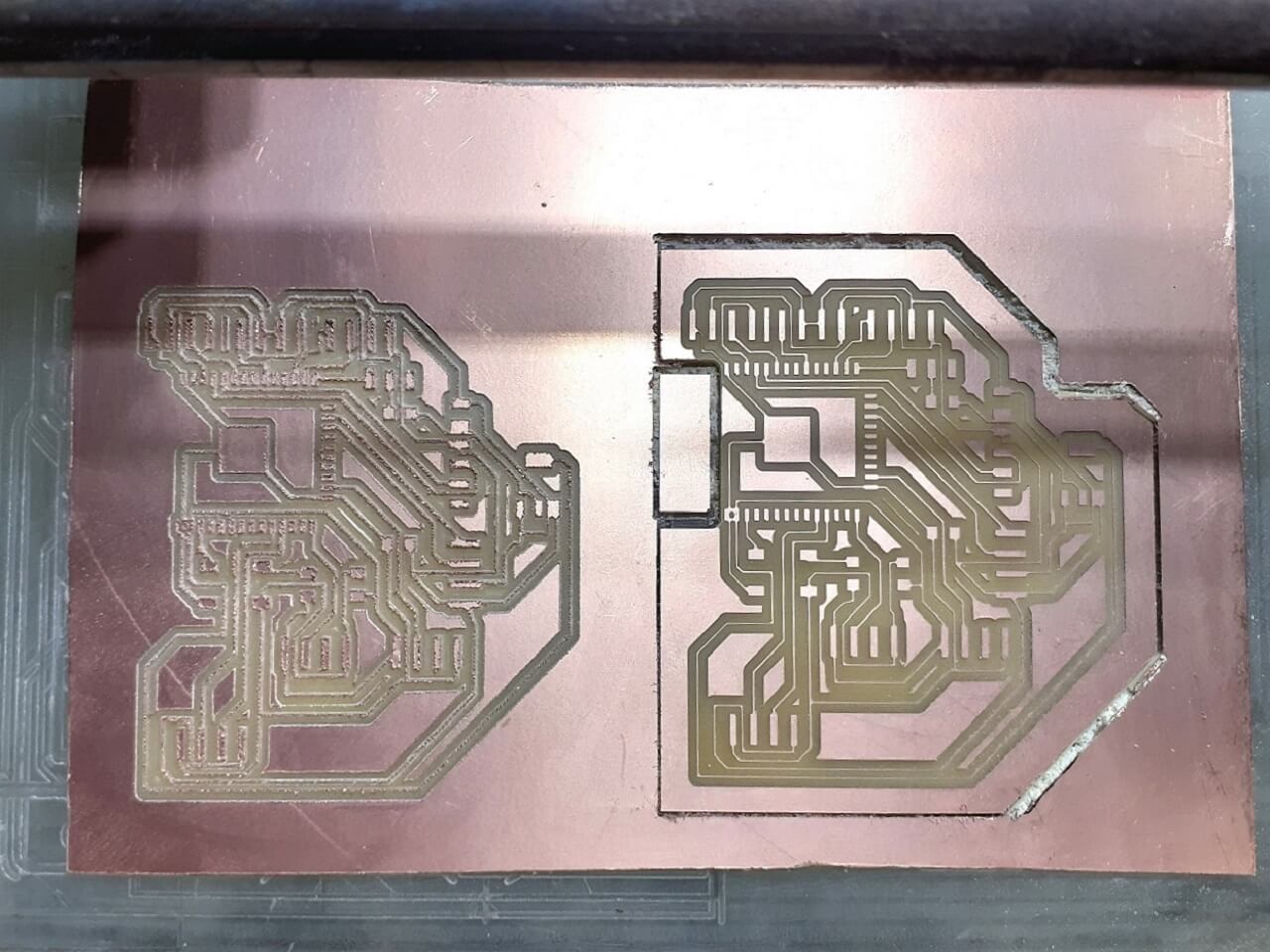
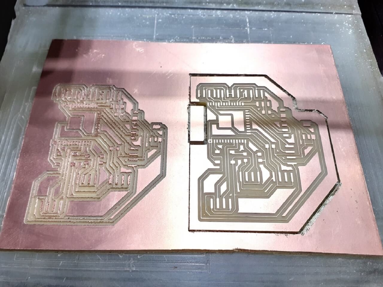
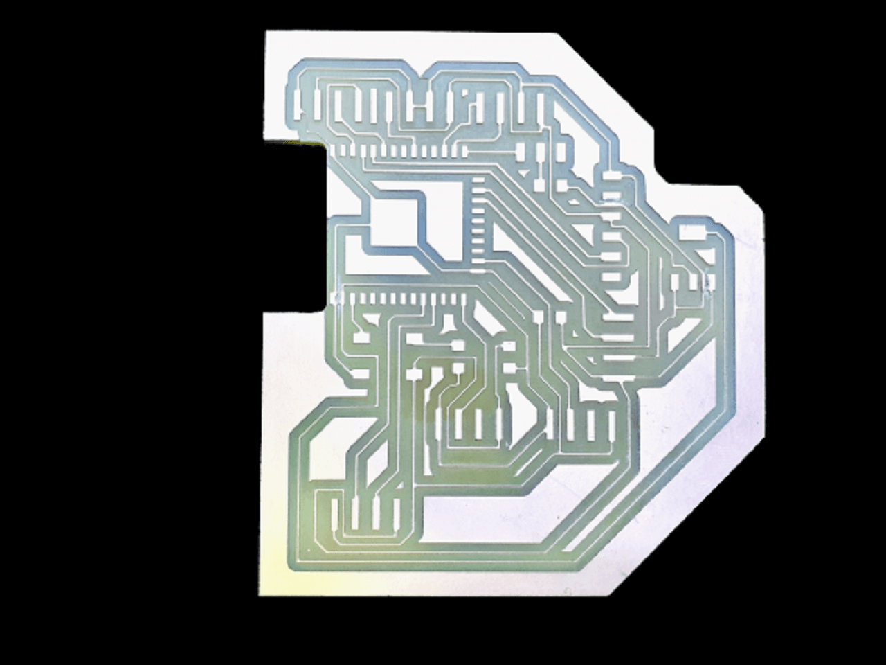
2. Milling my board
I used SRM20 machine to mill my PCB.
 |
 |
 |
 |
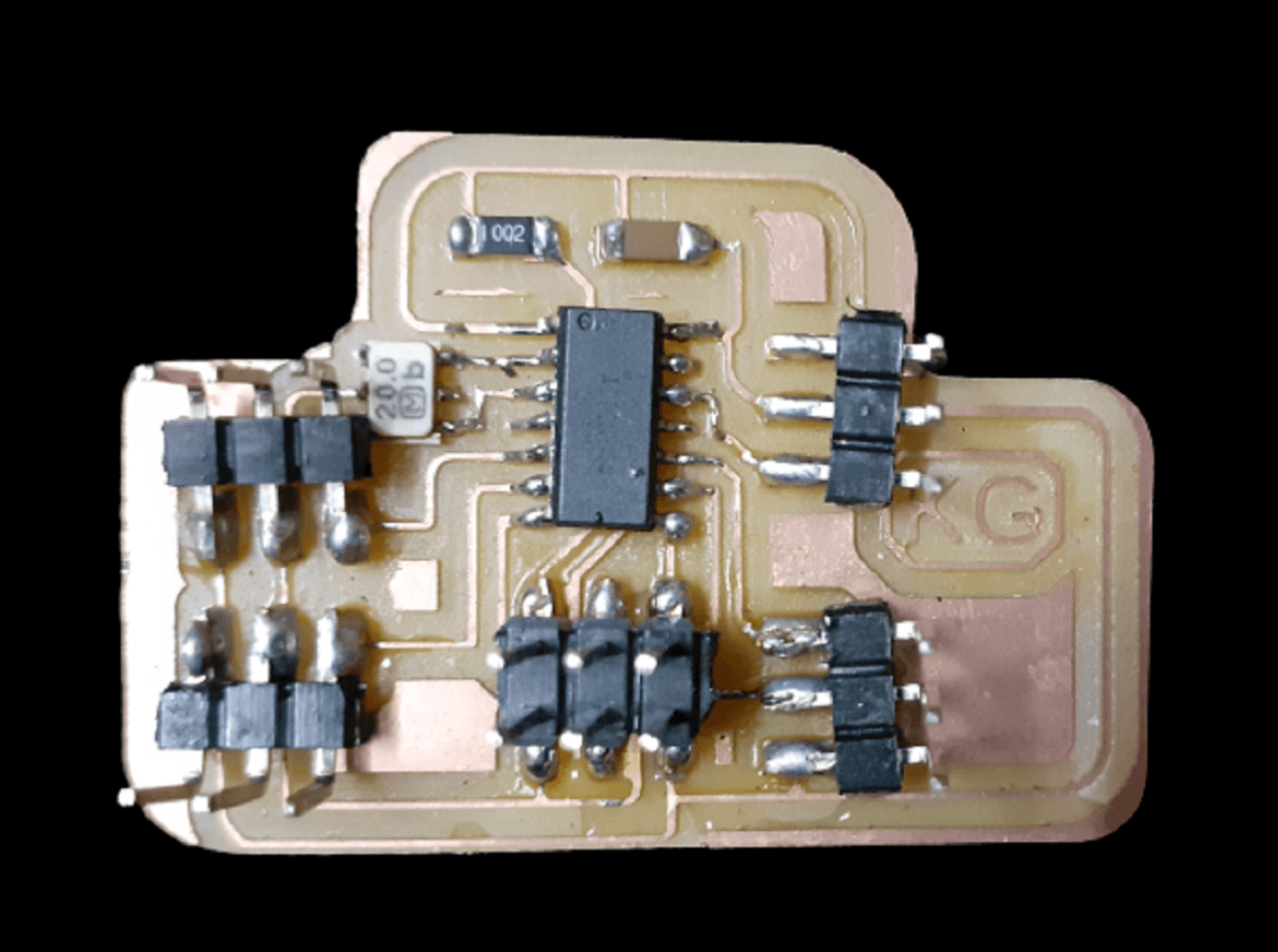
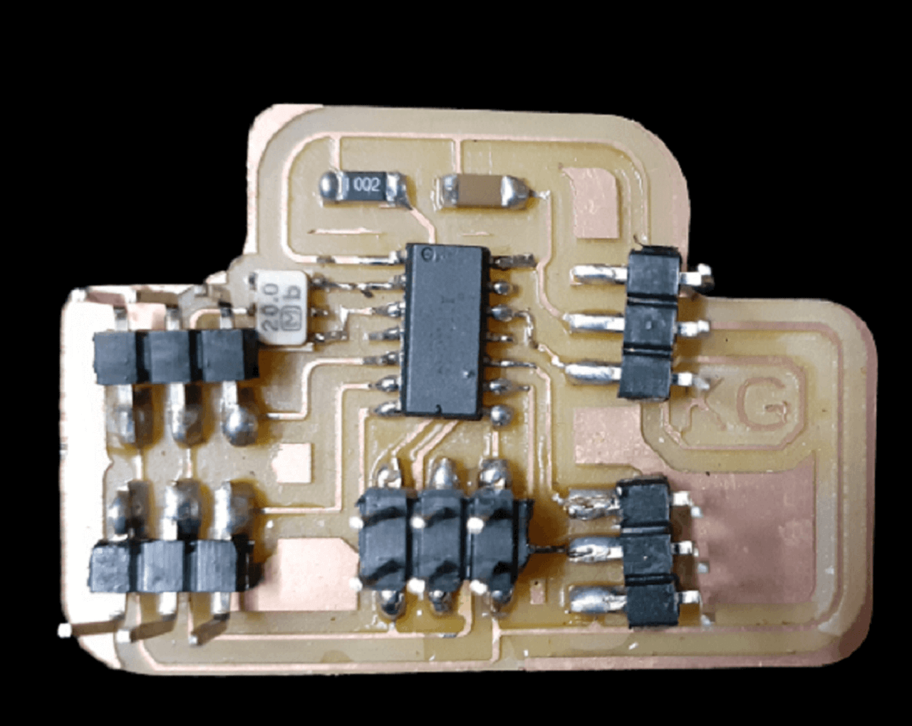
3. Stuffing my board
Components Required for the board:
1. Resistor: 10K- 1 Qty
2. Capacitor: 1uF- 1 Qty
3. Microprocessor ATtiny44- 1 Qty
4. Resonator: 20MHz- 1 Qty
5. 3x1 Male header pins- 4 Qty
6. Resistors: 100 Ohm- 1 Qty
7. Programming pin header: 2x3- 1 Qty
|
|
4. Programming my board
1. Connecting Relay and AC bulb to my board:
I used arduino IDE to program the board. Click here to see/copy the "Relay" program or download sketch from the cloud screen below.
2. Connecting DC motor to my board:
Click here to see/copy the "DC motor" programor download sketch from the cloud screen below.
3. Connecting RGB LED module to my board:
Click here to see/copy the "RGB LED" program or download sketch from the cloud screen below.
4. Connecting active buzzer to my board:
Click here to see/copy the "Buzzer" program or download sketch from the cloud screen below.
Designing my final project board
This week I designed, milled and stuffed my final project board as well. I made an attempt to program this board. However, I could not program it because of some issues that I have explained below.
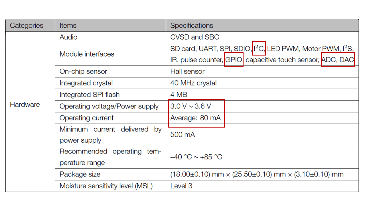
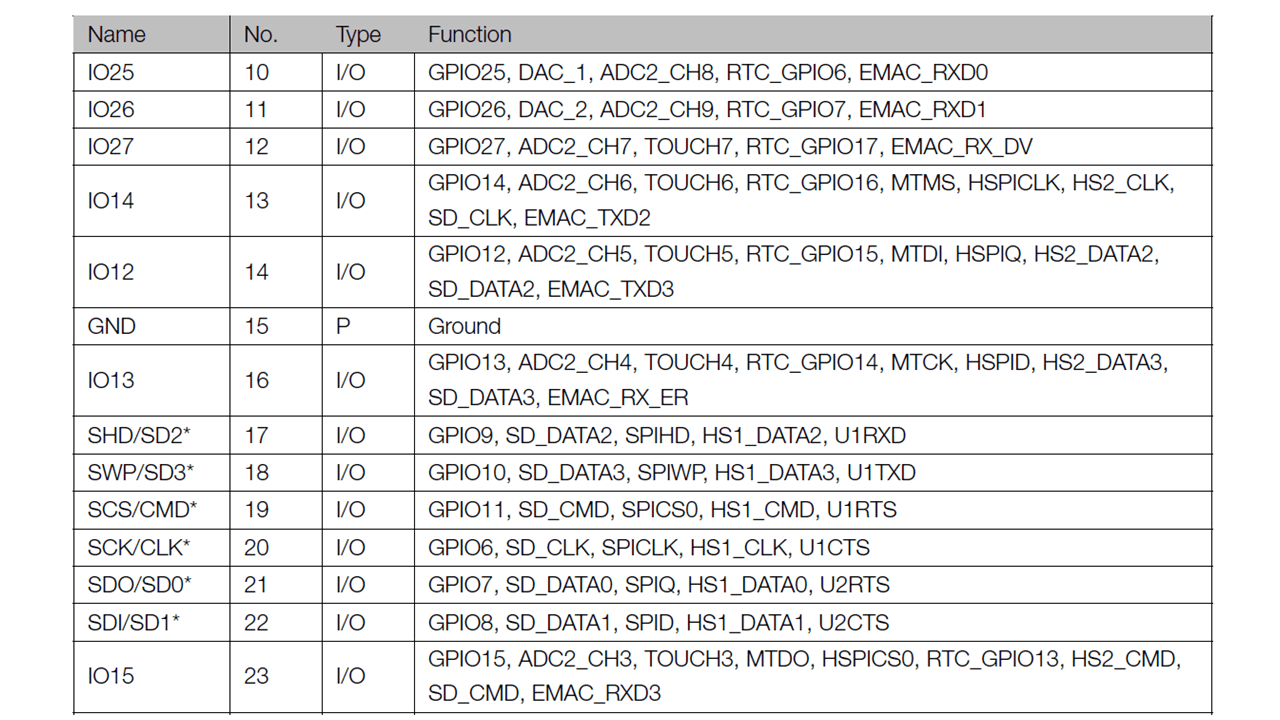
To begin designing my final project board, first I referred ESP32-WROOM-32 Data sheet to find out the pin-out of the IC to design my board. Below are the important specifications I looked in to while selecting ESP32-Wroom32 micro-controller for my final project board.
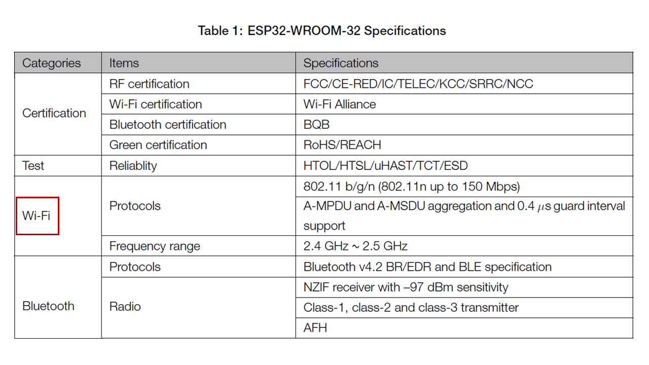 |
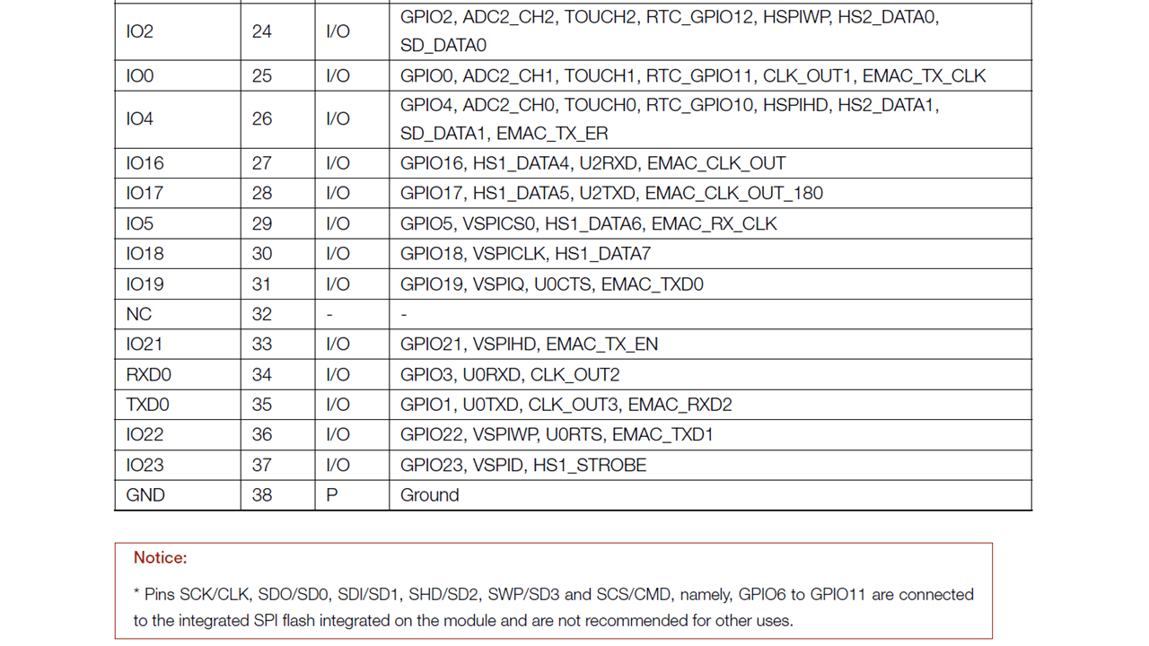
 |
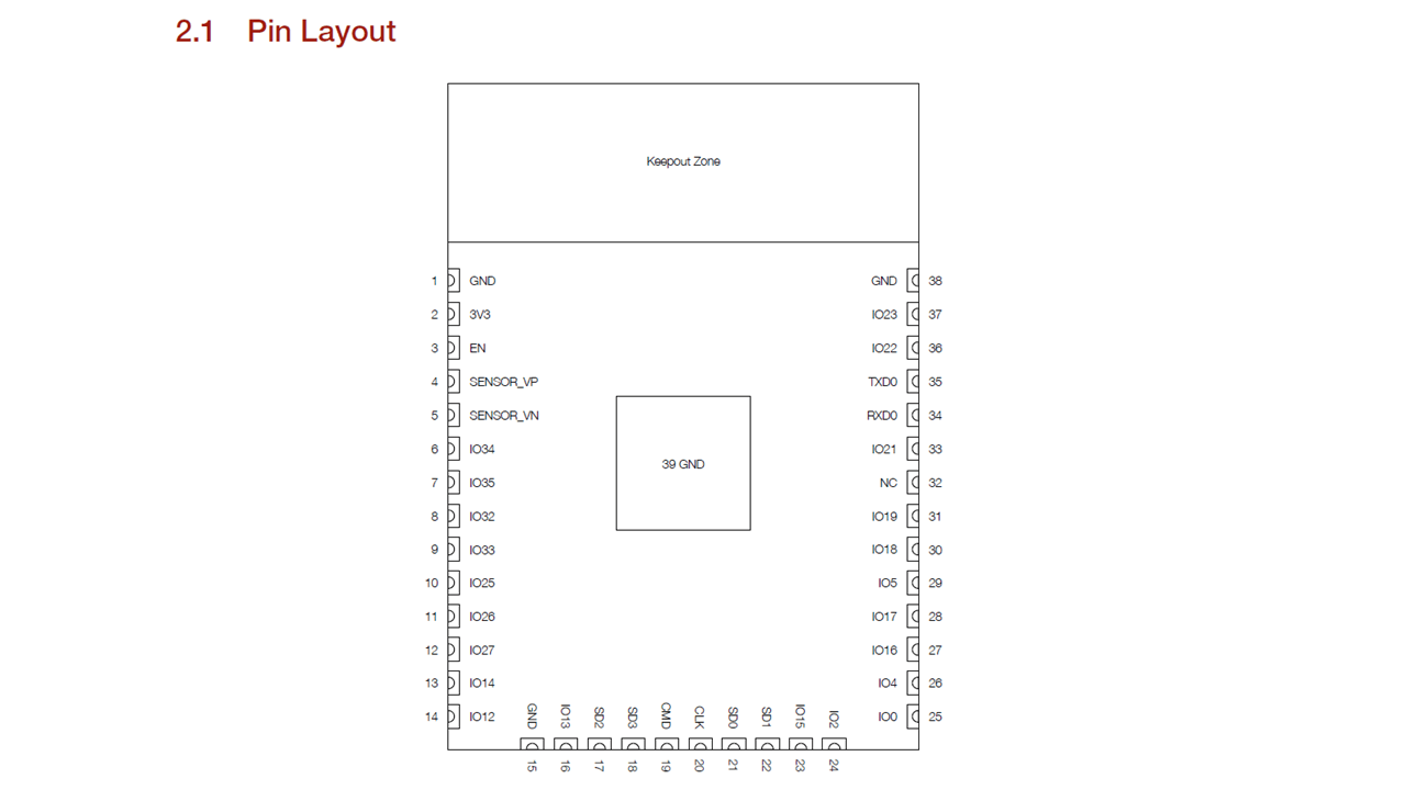
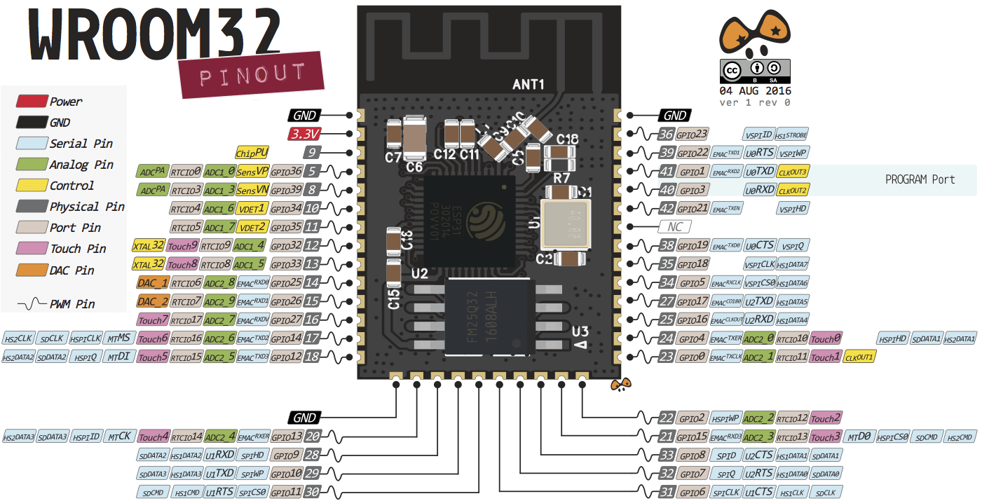
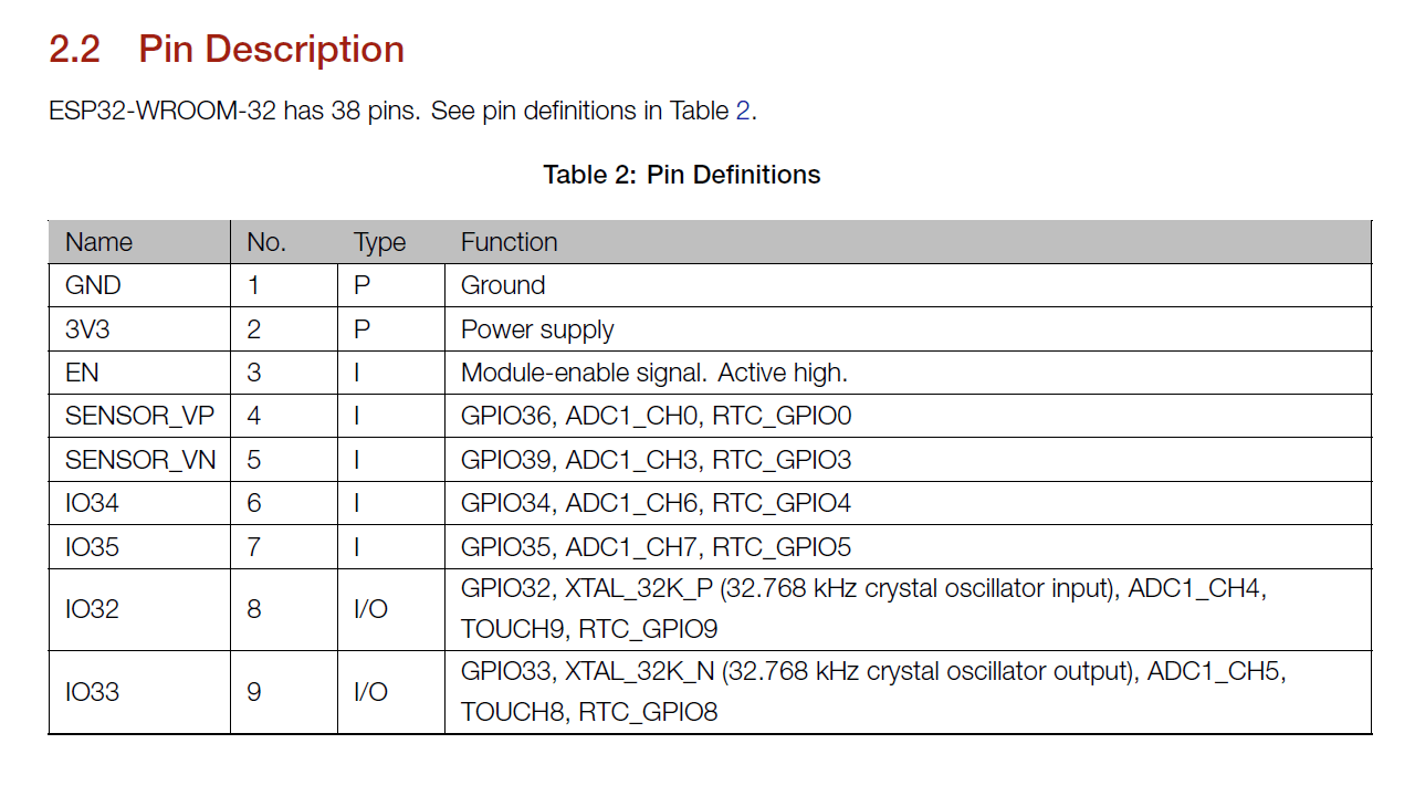
Below is the pin-out of ESP32-Wroom32. After understanding the pin-out and description of each pin from the datasheet, I chose pins for input and output devices that I will be connecting to my project board as shown below.
 |
 |
 |
 |
 |
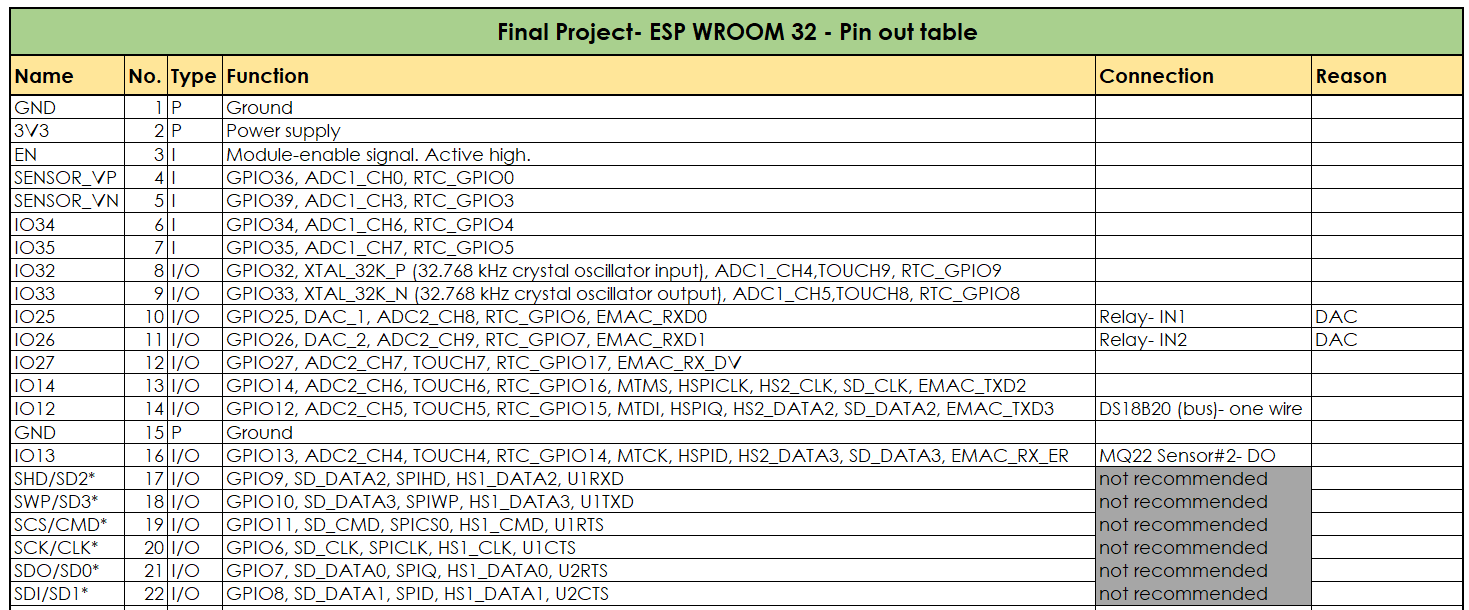
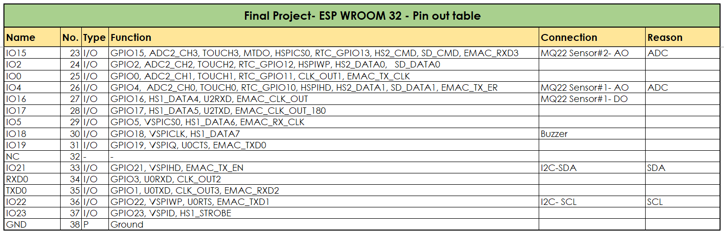
I then converted this table to an excel sheet for me to be able to map each pin to their respective input and output devices as shown below.
 |
 |
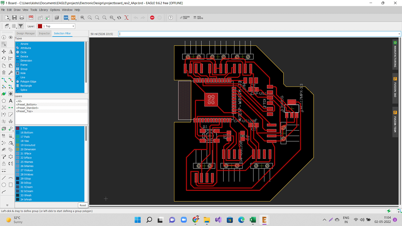
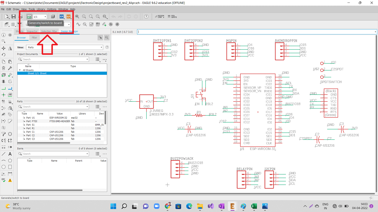
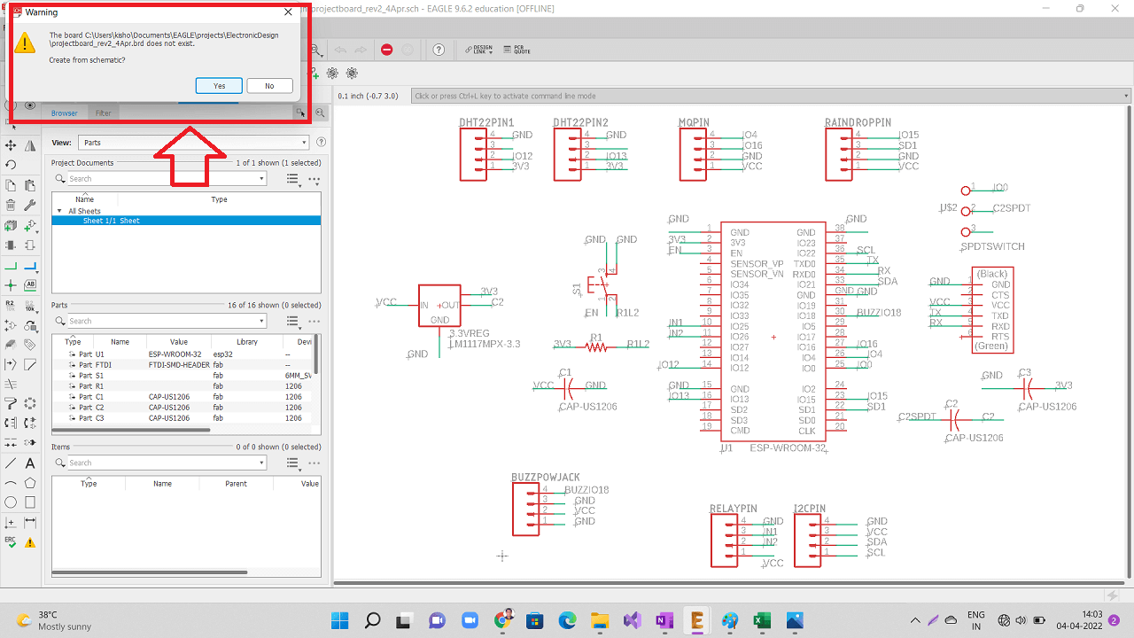
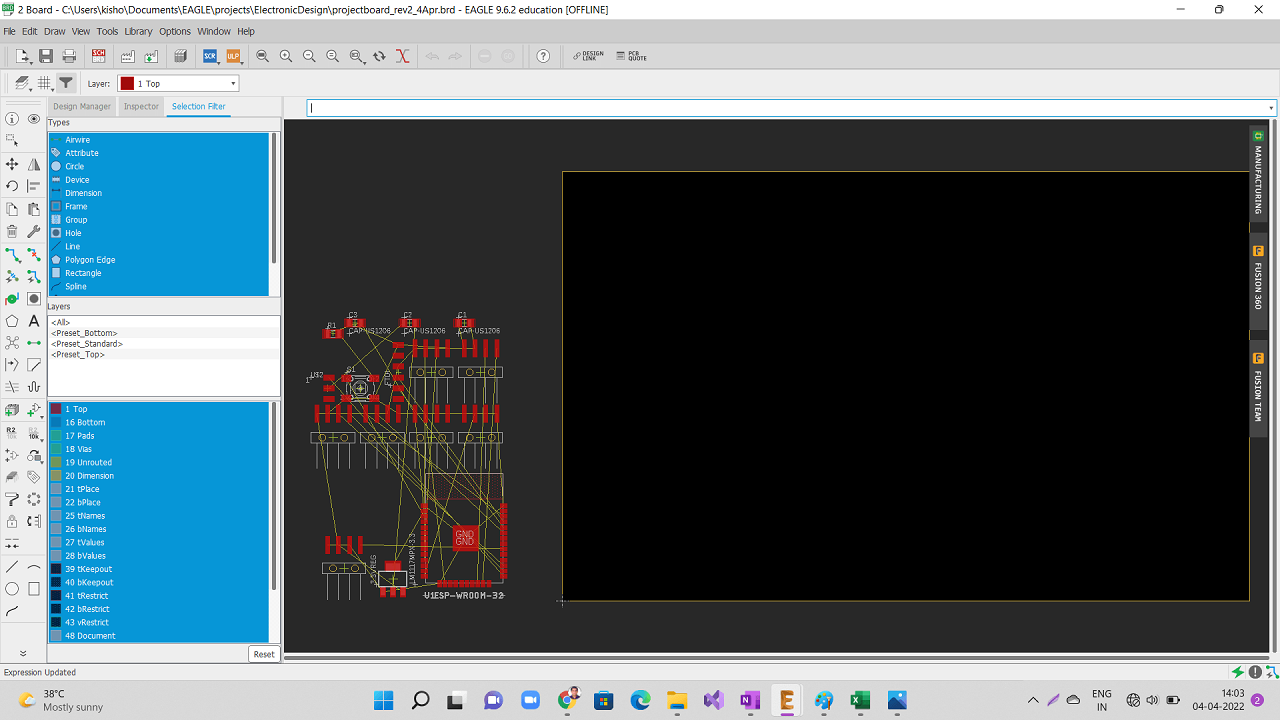
Using Eagle to design my final project board
I downloaded esp32 library for adding ESP32-Wroom-32 microcontroller IC to my shcematic and board as shown below. I referred this website to download the ESP32 library.
 |
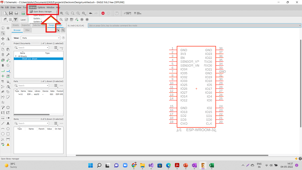
However, the pad size of the ESP32 in this library is too small to place the actual ESP32 microcontroller chip. So, I needed to increase the pad size of the chip from 55x25 to 60x32. First open library as shown in the steps given below.
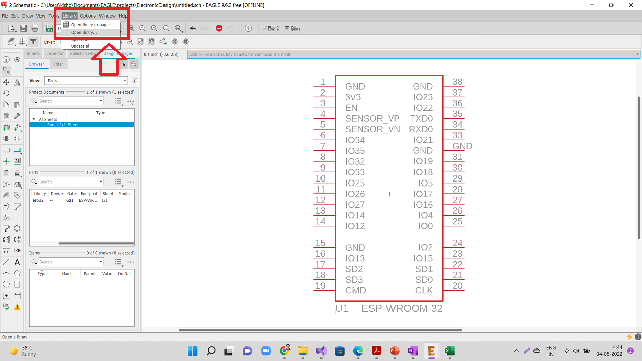 |
Open the original esp32 library that was just downloaded in earlier step.
 |
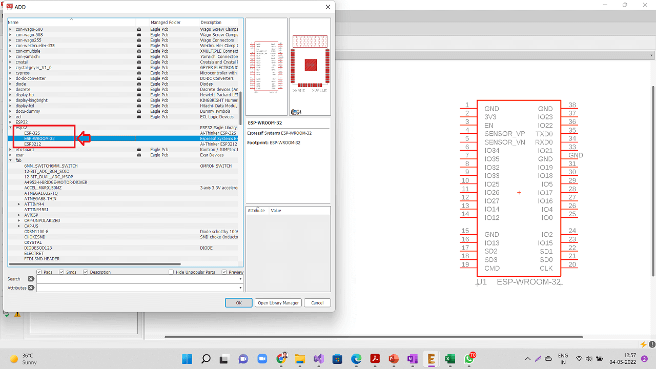
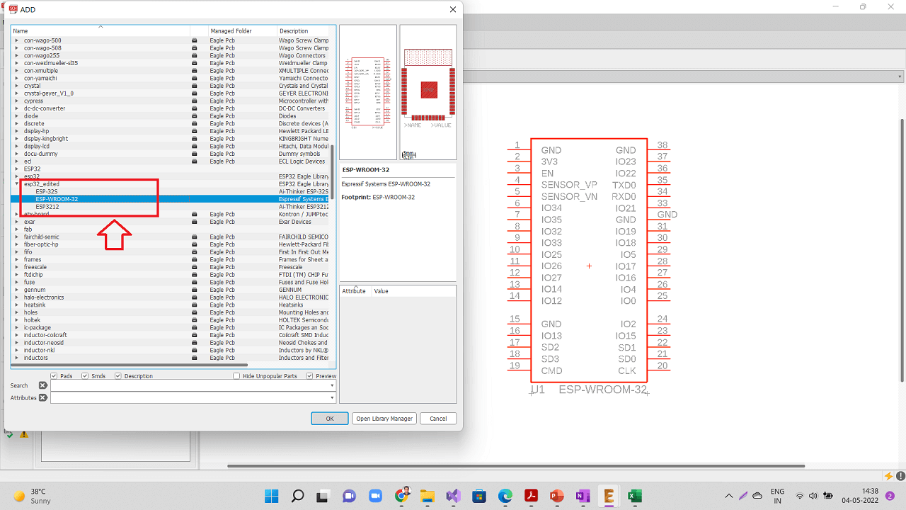
Open specifically 'ESP-WROOM-32' device from the library as highlighted below.
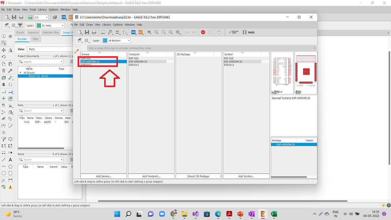 |
Click on the 'Footprint' button and click 'ESP-WROOM-32' again as shown.
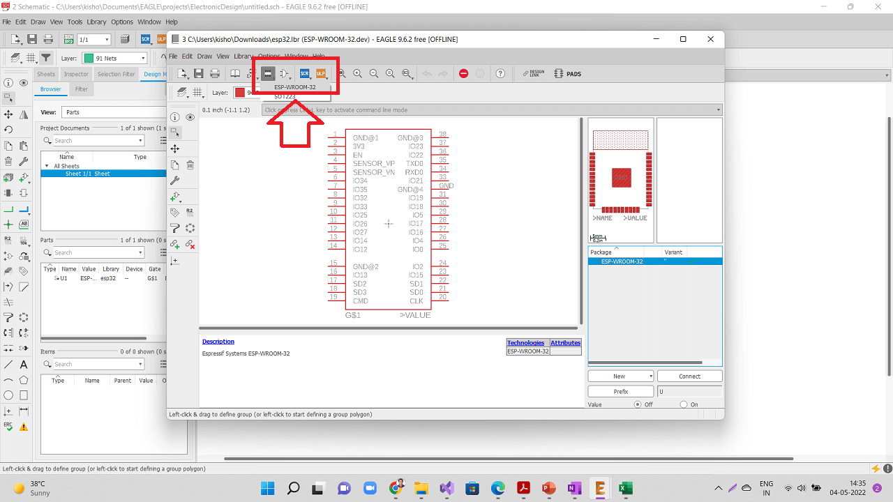 |
Following screen will be opened with the ESP-WROOM-32 device.
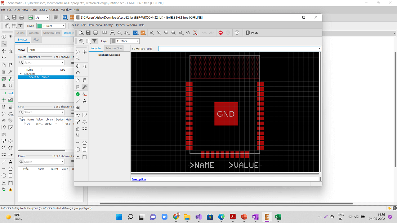 |
Run 'change smd' command to change the pad size as shown below.
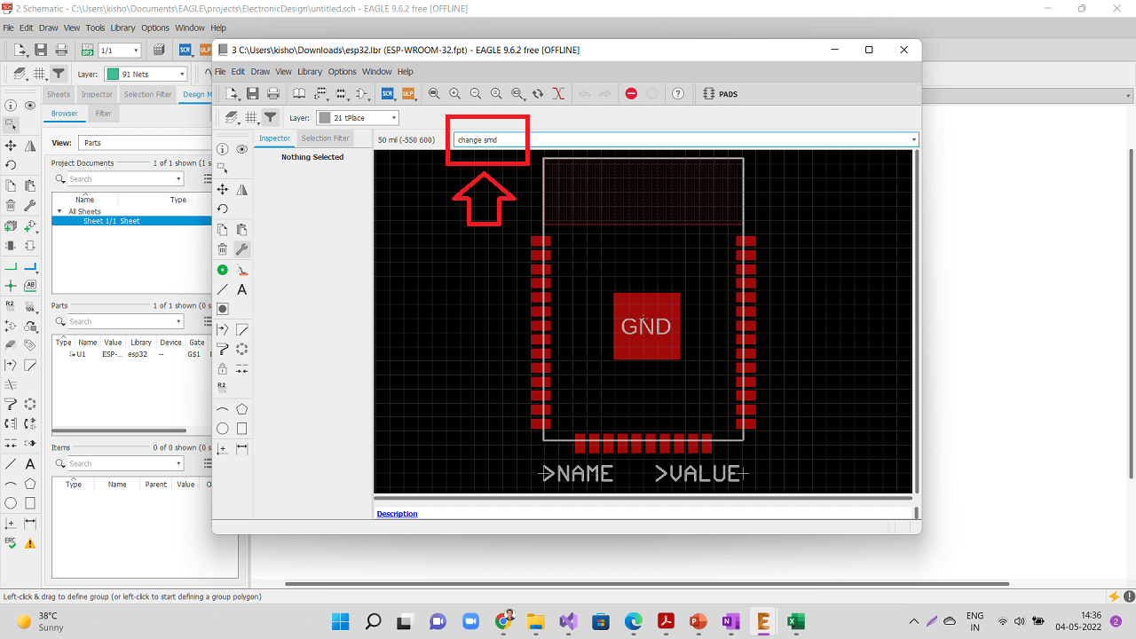 |
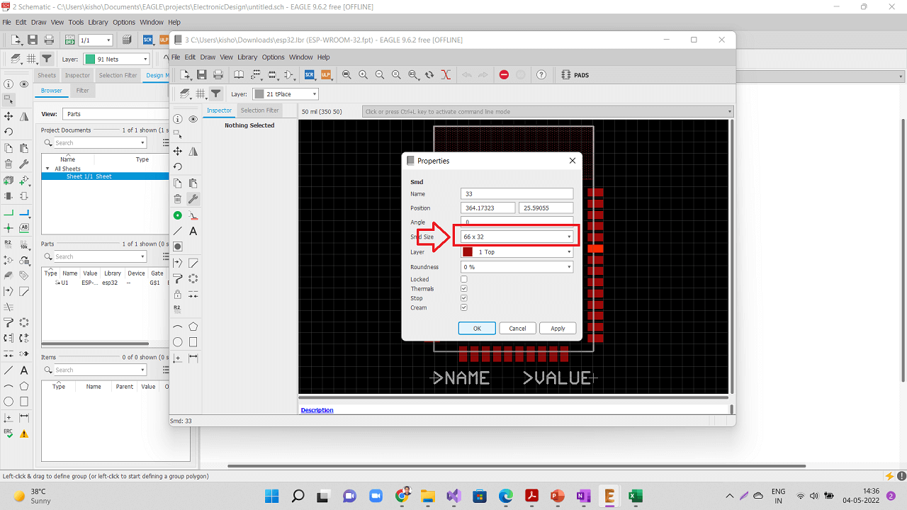
Change the footprint from 55x25 to 66x32.
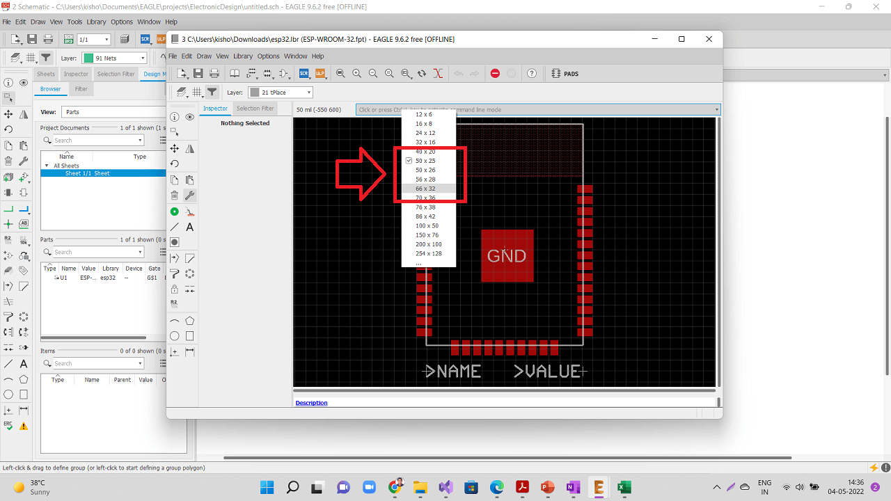 |
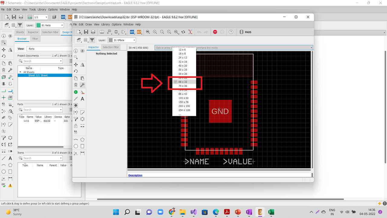 |
Right click on the component, go to properties and confirm whether the size has been increased to 66x32.
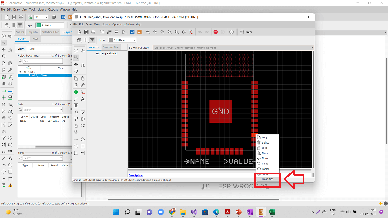 |
 |
Go to file- Save as- and save this modified library with a different name.
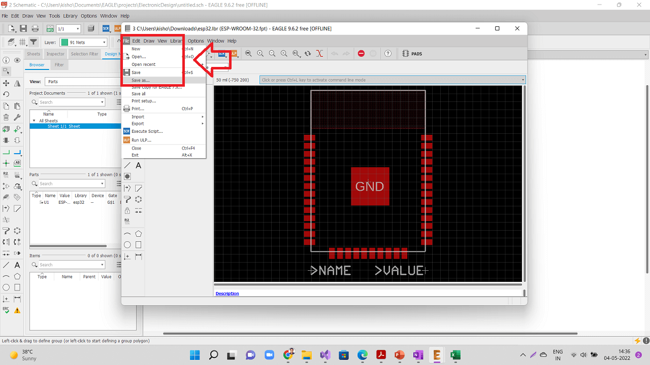 |
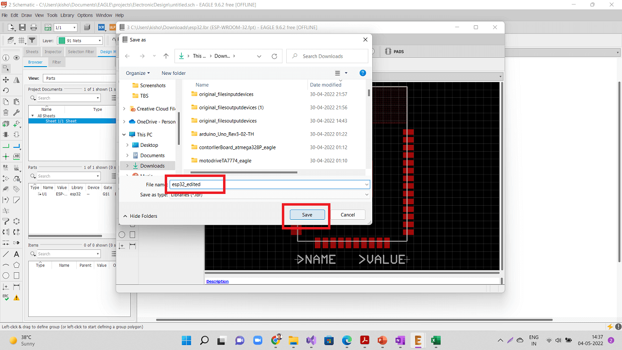 |
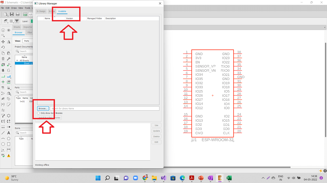
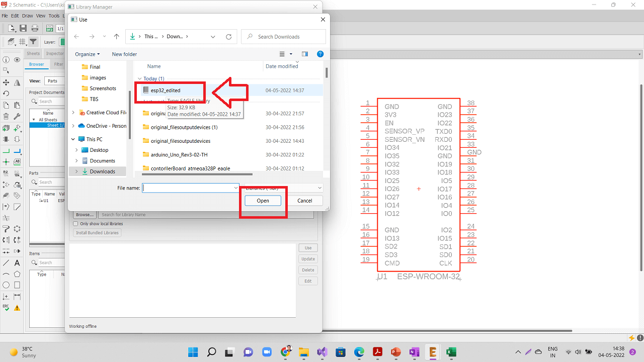
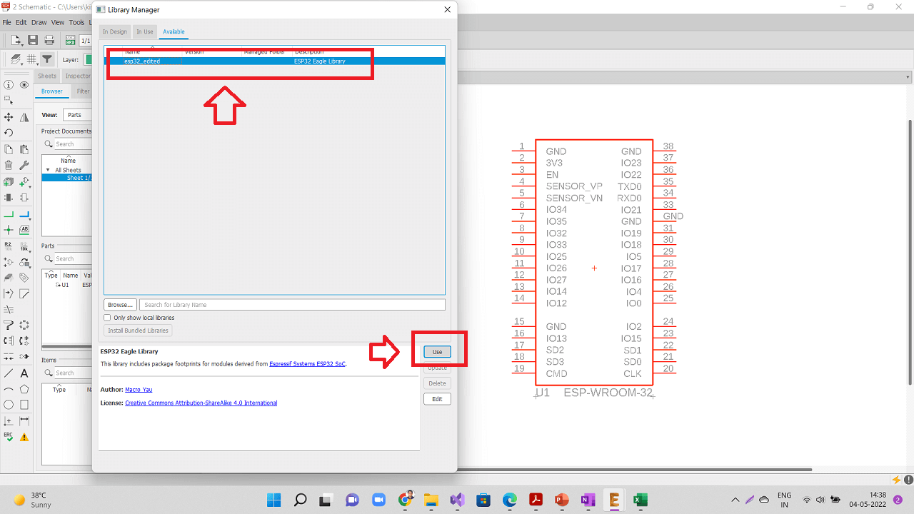
Again open the library manager and browse the new/edited library of esp32 as shown in the pictures below.
 |
 |
 |
 |
Browse the ESP-WROOM32 device from the edited/modified library as shown below.
 |
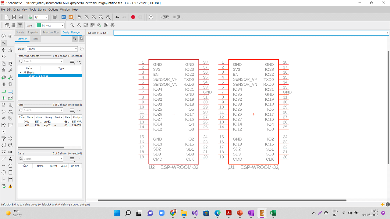 |
Delete the earlier component and verify through the property of the newly added component whether this component is from the modified library as shown below.
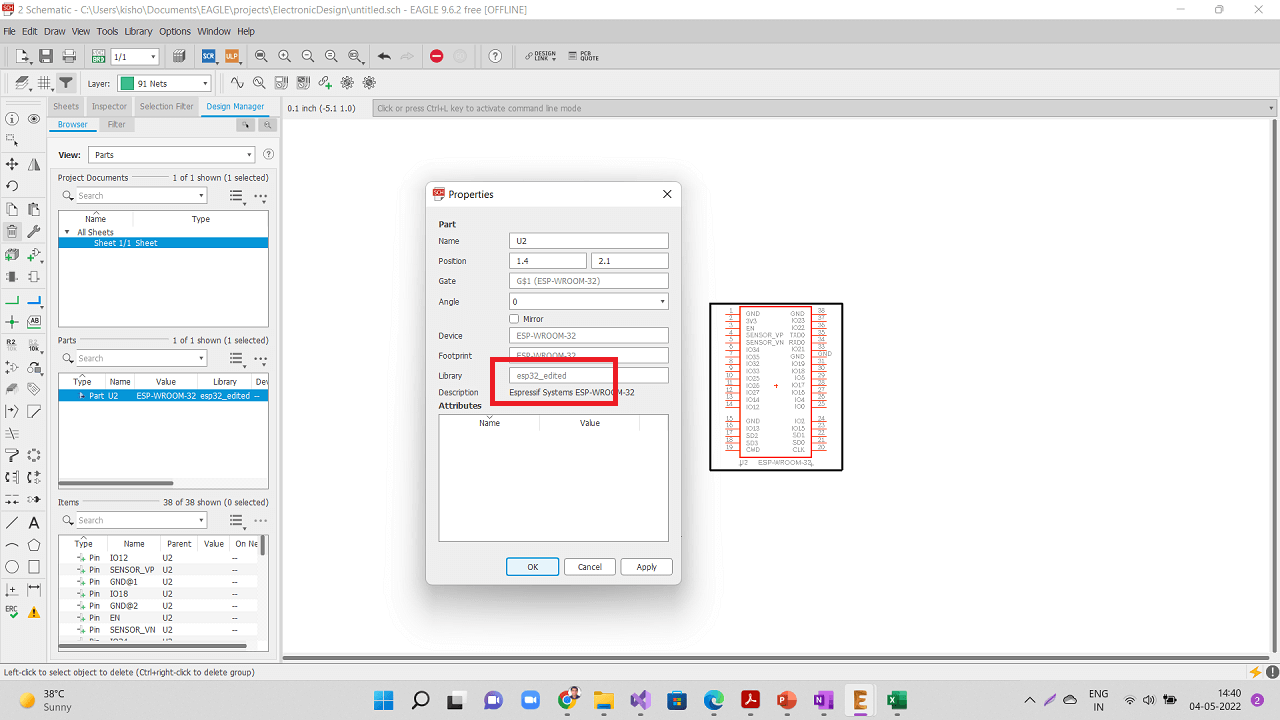 |
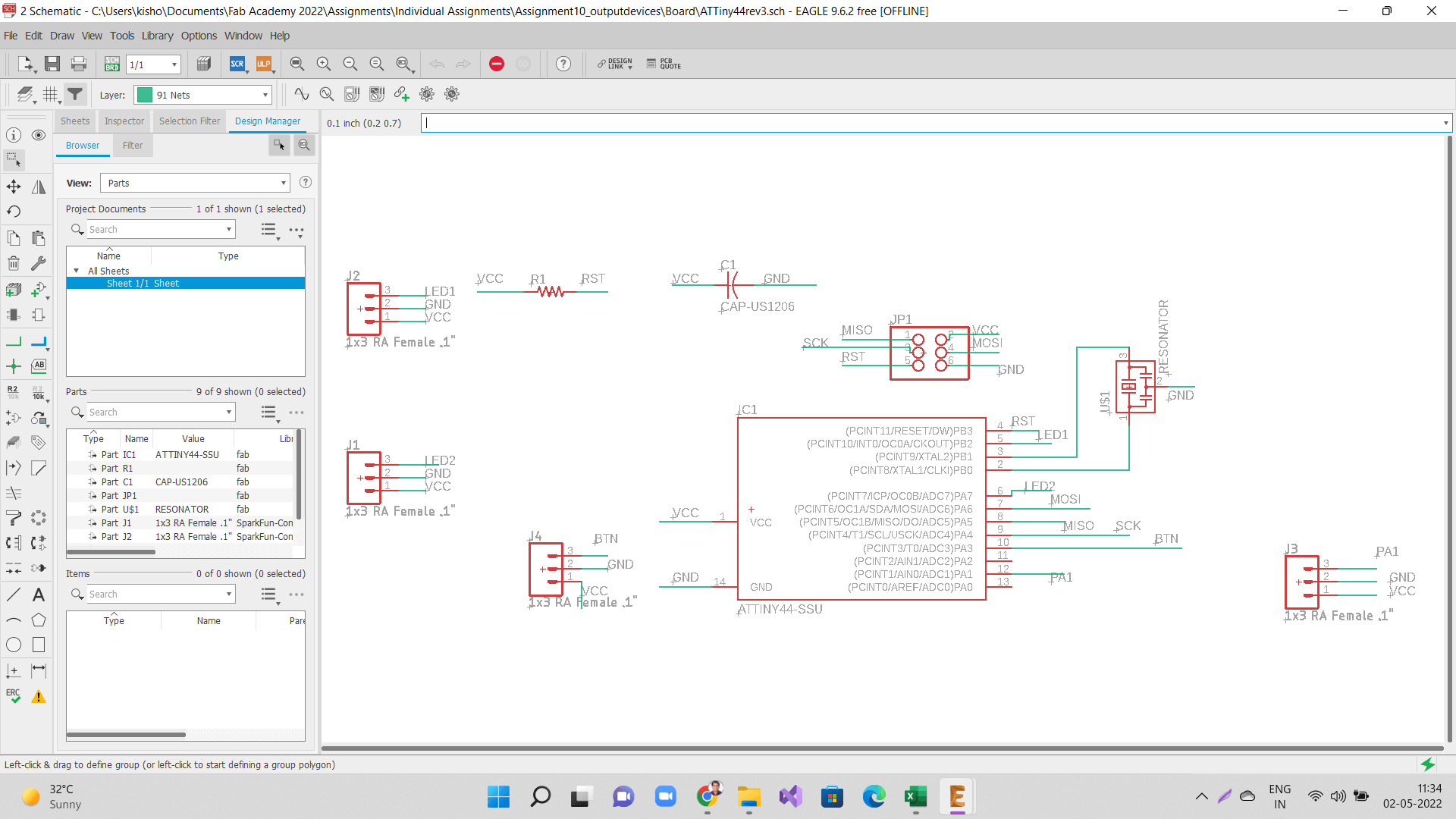
Continue designing the schematic as per the basic ESP32 board design given by Dr. Neil in this assignment. I added header pins for the input and output devices for my project. For 3.3V voltage regulator, I used the component from this library. For all the connectors, I used the components from this library
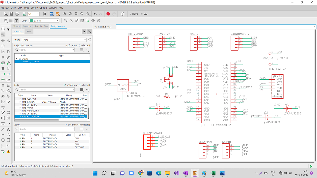 |
 |
 |
 |
|
 |
 |
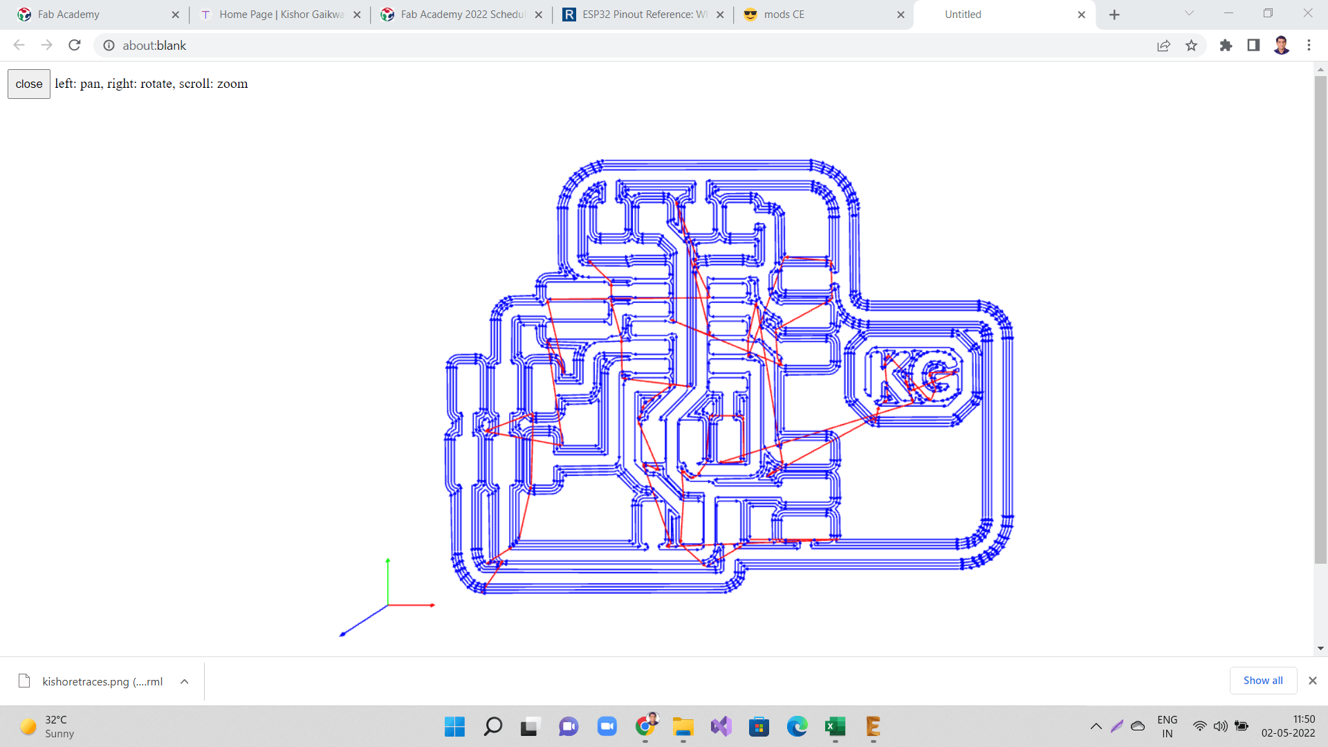
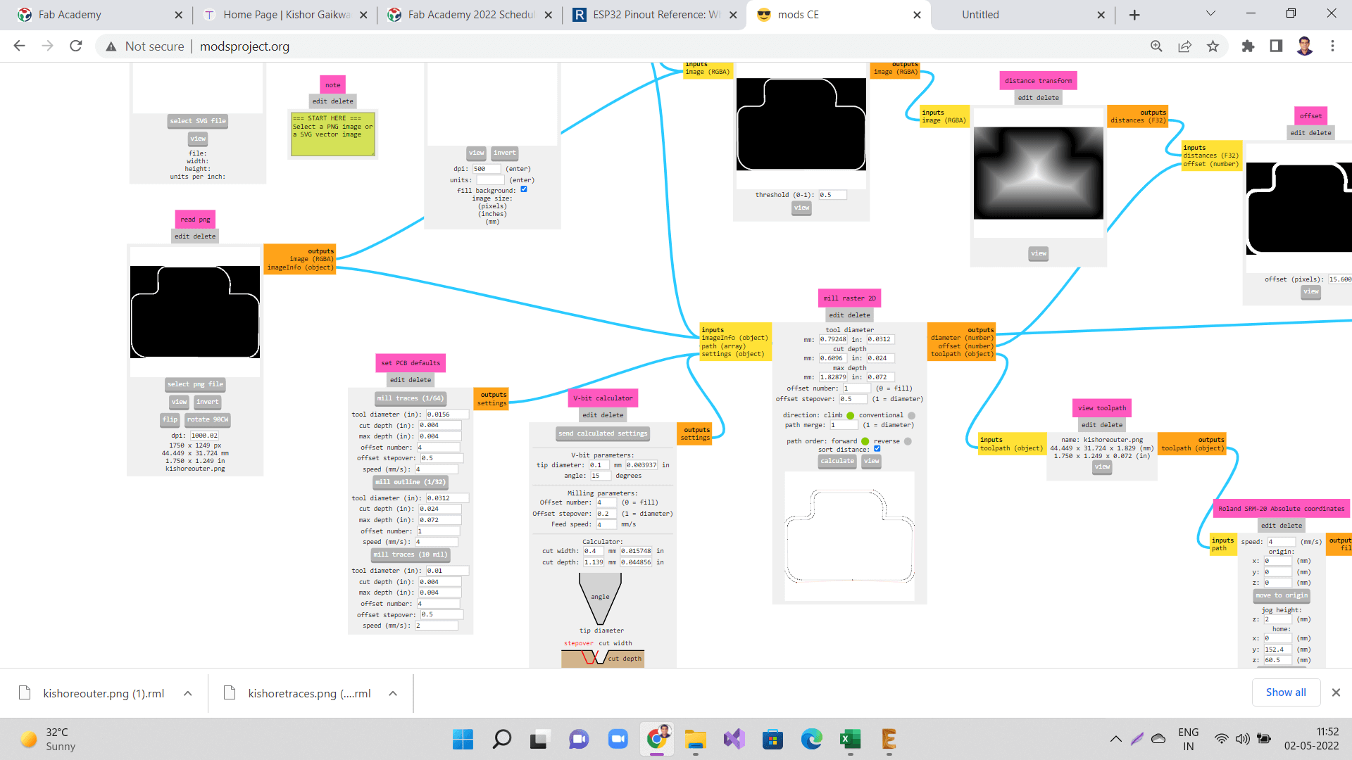
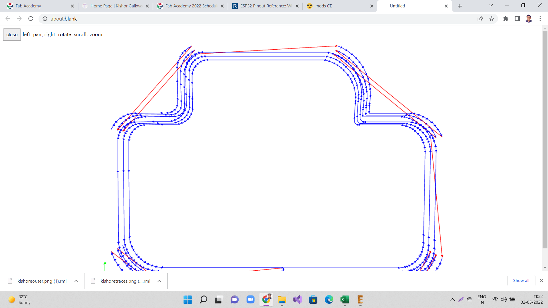
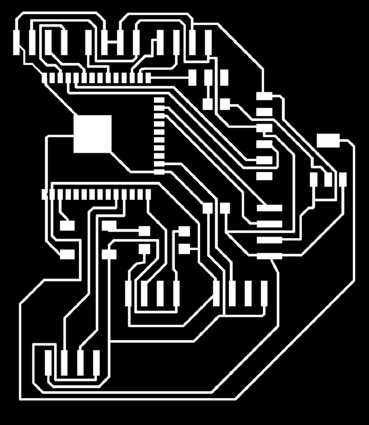
Milling my final project board:
 |
 |
 |
 |
 |
 |
 |
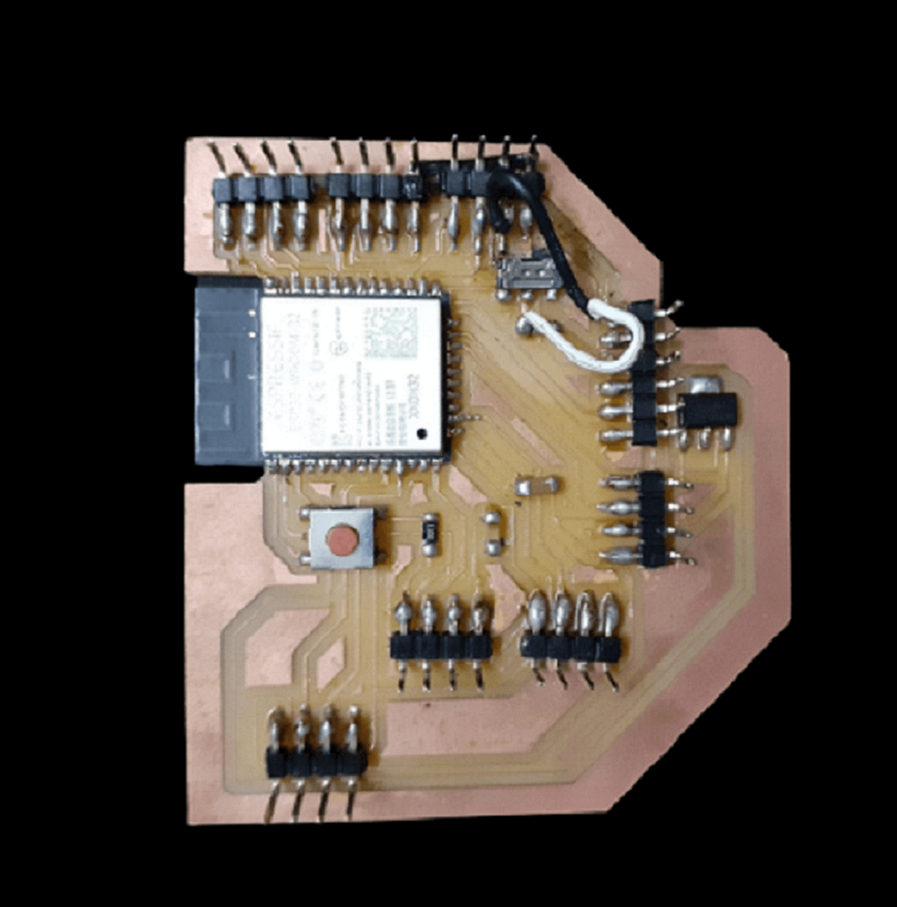
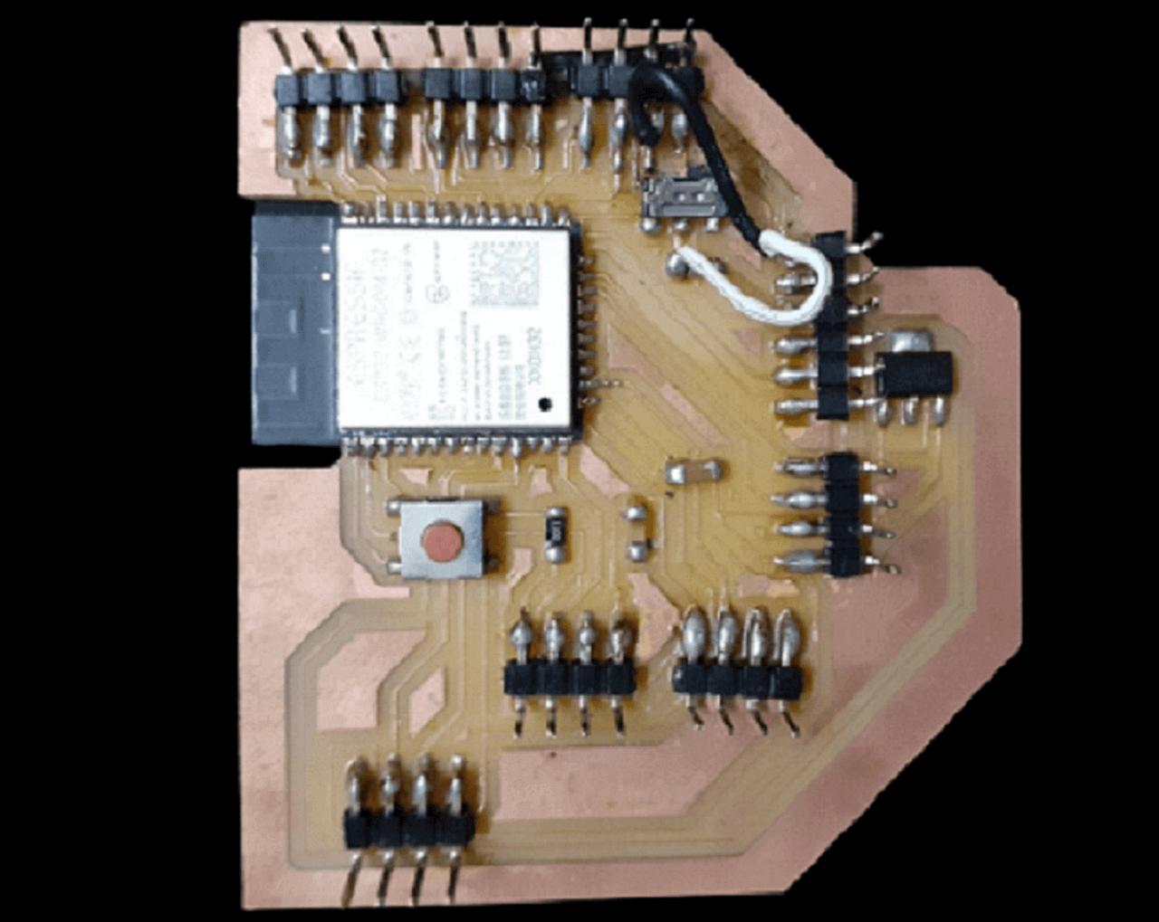
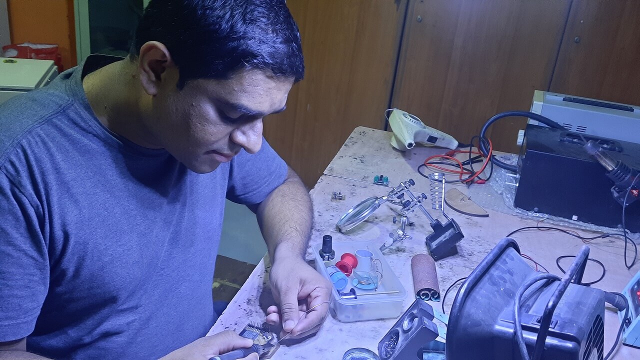
Stuffing my final project board:
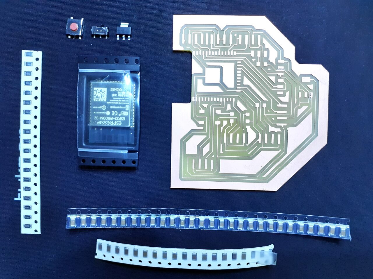
Components Required for my Project board:
1. Resistor: 10K- 1 Qty
2. Capacitor: 1uF- 1 Qty
3. Capacitor: 10uF- 1 Qty
4. Capacitor: 0.1uF- 1 Qty
5. Push button (No)- 1 Qty
6. Sliding switch- 1 Qty
7. 3.3v voltage regulator (SMD)- 1 Qty
8. Microprocessor ESP32 Wroom- 1 Qty
9. FTDI Pin (6pin)- 1 QTY
10. 4x1 make header pins
 |
 |
|
Issues with my final project board:
I designed, milled and stuffed my final project board. When I started to upload a basic program in to my board, it was giving timeout error. I checked connectivity between all connected points in the board and could not find much. I still kept facing the same timeout issue multiple times. So, my instructor Mr. Suhas and I decided to check the schematic one by one. We found out I did not make following connection in my schematic and there was not trace obviously.
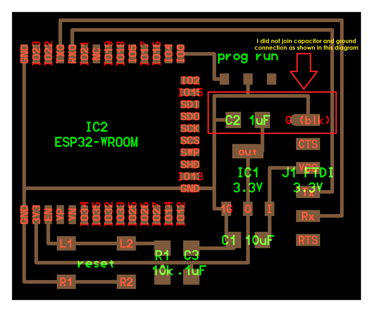 |
So, I had to place a jumper wire between GND and one end of capacitor that is connected to the sliding switch as shown below. My board started working and programs started uploading. However, I did not try using this board at all for any output device for this week because of the time crunch and machine week was my priority, so I stopped here and used my board in input devices week onwards. I have documented it in those assignments.
|
Click here to go back to the top
Download Original Files
Click here to download all original files.
Click here to go back to the topWhat went well
In group assignment- As a group, we went through various output devices. We could measure the power consumption of a couple of output devices.
In individual assignment- I tried connecting various output devices to arduino board as a hands on experience. It helped me in designing my output devices board. I was able to complete designing, milling, soldering and programming of my output devices board on time. I was able to connect and run relay, DC motor, RGB LED module and an active buzzer on my board. I was also able to complete design, milling and soldering of my final project board in this week itself.
What went wrong
In group assignment- There is nothing major that we did wrong in the group assignment. However, we could have tried measuring the power consumption of stepper or servo motor.
In individual assignment- In my final project board, I missed connecting the capacitor to a junction of GND and sliding switch. It was causing issues with program uploading. However, I had to add a jumper cable to make this working.
What I would do differently
- I would try connecting stepper motor or servo motor to my output devices board. However, I am going to connect LCD, relay to my final project board.
- I would measure power consumption of output devices on my final project board.
Learning Outcomes
- I learned how to modify the footprint of the components in eagle library
- I learned how to do programming for various output devices, which helped me in make a machine week also.
- I learned various output devices, their connections, other components needed like I2C, stepper drivers, etc.
- I learned how to manage my time well considering multiple priorities like make a machine week and my own assignments including my final project.