
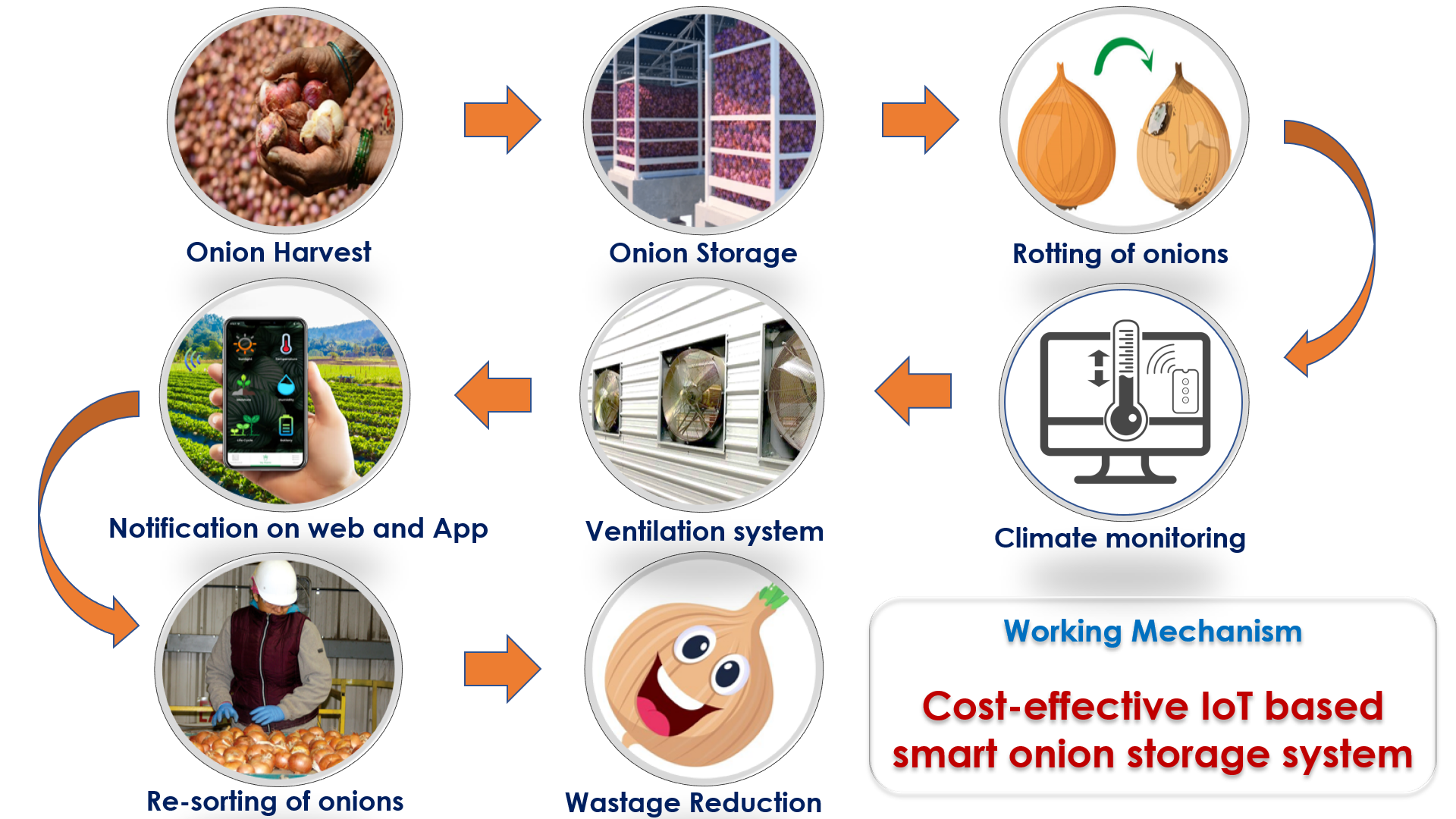
Title: Cost-effective IoT based smart onion storage system
Problem Statement
In India and other developing countries, there is almost 40-80% of onion harvested is spoiled because of various reasons. One of the prominent reasons is in-proper handling and unscientific ways of storage. Also The cost of cold storage is almost 10-12 times the cost of natural ventilated storage and 20 times than the traditional unscientific ways of storage, which is too high for a marginal farmers of a developing country like India.
This problem results in major social and health problems in India as a consequence of major finacial losses to the farmers.
Objectives of the Project
My objective is to solve the storage related spoilage, rotting and losses through a cost-effective, IoT based smart mechanism of post-harvest onion bulk storage.
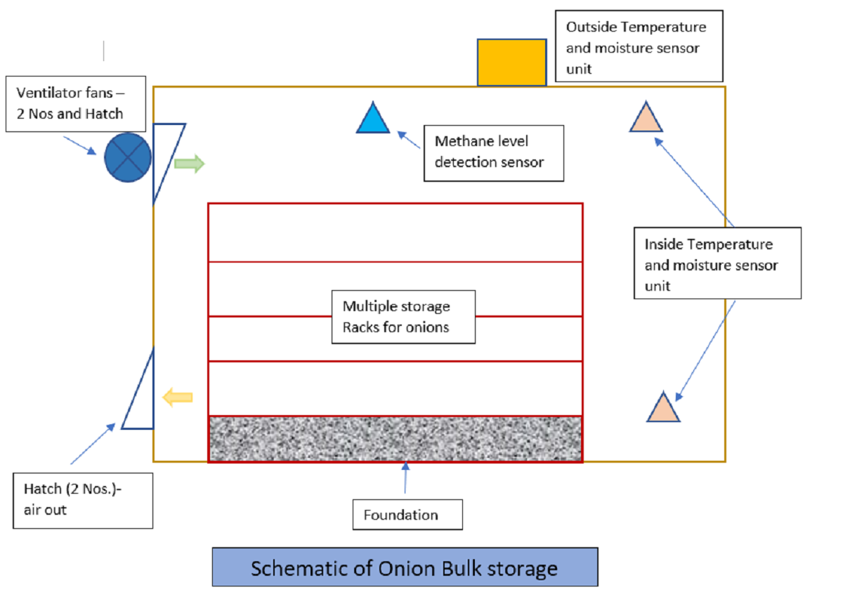
The onions need to be stored in well ventilated area. My idea is to measure the temperature, humidity in and outside the storage room along with measuring the levels of Methane gas emmitted by onions stored. More the level of methane means the onions have started rotting. Upon measuring and monitoring the humidity, temperature and the methane concentration, the storage house will be ventilated and aerated sufficiently to keep the produce dry and cool.
Abstract
Having been cultivated for 5,000 years, the onion has been a vital part our salads and meals along with its countless health benefits and strong aroma. The onion is the oldest and most widely used vegetable that can be cultivated in all types of soil all around the world. Being an irreplaceable aroma for the meals, the onion creates a large economy with the production of almost 100 million tons of round the world. The United Nations reports that the onion is grown in at least 175 countries and this figure doubles the number of wheat growing countries. Asia is the largest producer of the onion with a market share of 65 percent, while the Americas, Europe and Africa each has just over 10 percent of the market share.
China is the leader of onion production with 23 million tons in Asia and followed by India with production of over 19 million tons. China and India are followed by the United States with the production of over 3 million tons. Other large onion producers are respectively Iran, turkey, Pakistan, Egypt, Brazil and Mexico.
Although Asia has the biggest share in terms of production area and quantity, it does not rank as the leading Market in the global onion Market. This is due to high population density, insufficient storing spaces and the fact that they can't come out to foreign markets. While countries aim to increase their production for their citizens, they try to sell their surplus products on global markets for economic growth. If new investors prefer yellow onions considering the demands of developed countries markets, they should know that they would have a large market share. Nearly 90% of onions are consumed within the country they are grown. Therefore, the onion does not stand out in many parts of the world.
Traditional methods of storing onions are drying them with their stocks on and storing in a cool shelter, cave or dark storage after they are harvested until they are consumed. However, between 40 and 80 percent of the onion stored with this method result in spoilage. Neither economy nor our planet can afford these kinds of spoilage anymore. Onions now are stored in cold storage after the harvest. First onions need to be dried for a few days, then starts the maturing stage that enable skin and color formation to specific to the onion cultivated. Onions are prepared for cold storage by lowering the temperature at a maximum of 0.5 degree Celcius per day. Depending on the onion variety, they are stored at between 0 and 2 degrees Celsius in cold storage. Onions can be stored in cold storage up to 10 months without spoilage. Ventilation is vital in onion storage. After storing, onions are not transported straight from the cold storage before they are put on the market, but kept in temperature-controlled conditions in order to prevent condensation. Because of condensation, sprouting will happen immediately after they are taken out of cold storage resulting in poor pricing in the market.
Cold storages involve little difficult and elaborate processes and it is still not able to solve the problems of a marginal farmers in developing countries. The cost of cold storage is also a major factor, which is almost 10-12 times the cost of natural ventilated storage and 20 times than the traditional unscientific ways of storage, which is too high for a marginal farmers of a developing country like India.
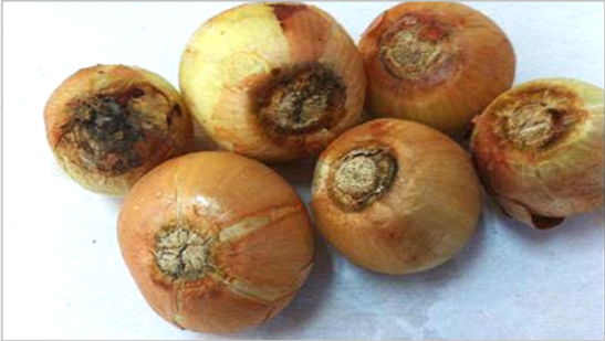
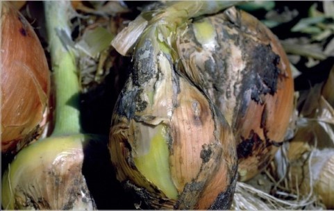
Types of rotting and infections in onions
Only 20 million tons of global onion production of 100 million tons are stored with modern storage methods and spoilage still continues. Weight loss, sprouting of bulbs, rotting, bacterial and fungal infections are some of the ways the onion spoilage happen. Neck rot (rotting at the neck of the onion), bacterial rot, basal rot (fungus infection through wounds and scars at the base of the bulb) and other diseases are resulted out of improper storage.
 |
 |
 |
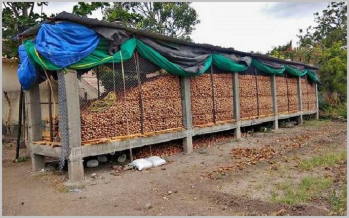
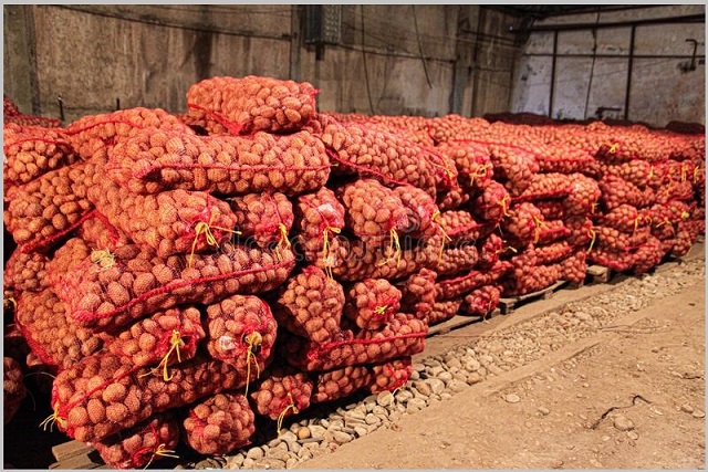
In developing countries like India, proper handling and unscientific ways of storage is a matter of great concern. Onions are stored in poorly ventilated temporary structures. Each farmer has created their own storage method based on their needs, experience and resources available. These unscientific ways of storage result in higher losses in storage. Actually, losses start immediately after harvesting. The facility of onion storage post harvesting needs to be made available right at the time of sowing of seeds itself.
 |
 |
Social and Health Problems:
The marginal farmers in India, who can neither afford the cost of cold storage nor the huge of produce losses. With less to none yield, these farmers end up in committing suicides, which is a major social and financial issue. At the same time, to save their crop from these spoilages, they use a lot of pesticides to prevent these infections post harvesting. This ultimately results in creating long term health problems for people.
Click here to go back to the topSketch of the Final Project
Following is a sketch of the proposed cost-effective IoT based smart onion storage system.
 |
 |
Click here to go back to the top
Computer-aided Design
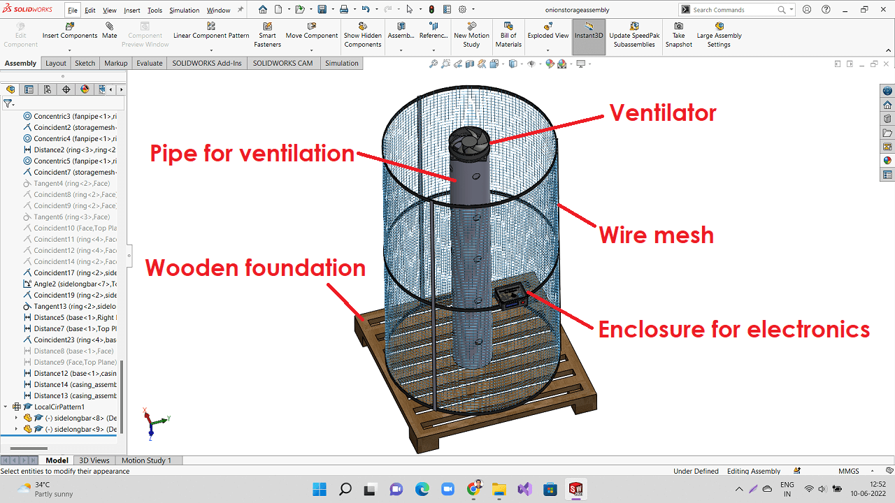
Creating 3D objects and Assembly of Parts of my Final Project in Solidworks
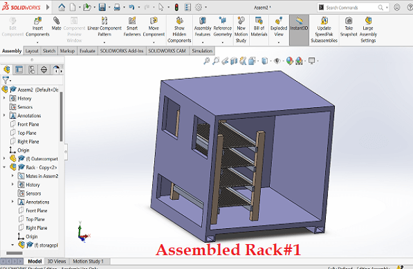
I used SolidWorks to create 3D models of some of the parts of my Final project. I also used Assembly module to create a basic assembly of my final project. I used rendering to change the appearance, texture and colors of the components.
First, I created 3D models of some of the major parts of my final project concept. I then assembled them as shown below.
 |
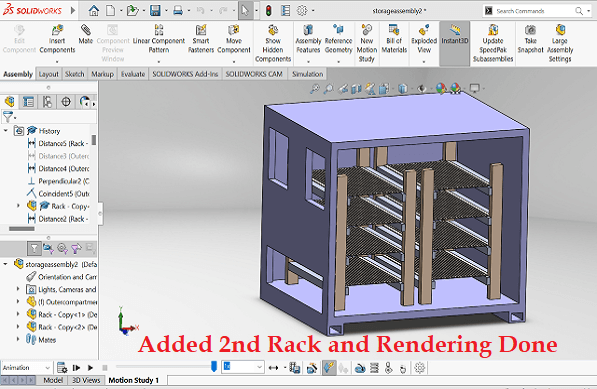 |
I used animation wizard in Solidworks to create a small animation of the final assembly for better visualtion of the project through animation. Please find below the video. For more details on this, pls go to my CAD assignment.
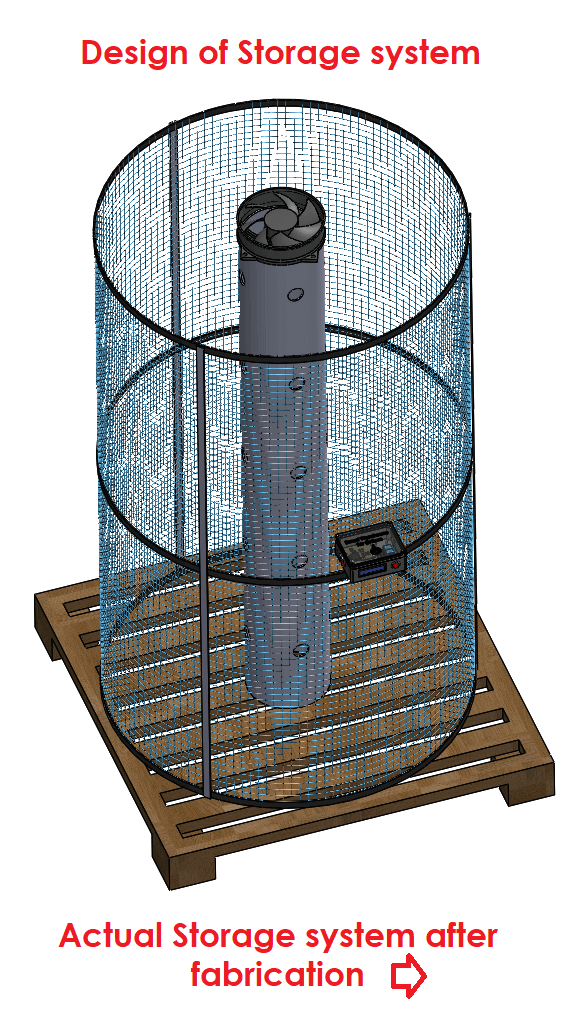
However, this design was my initial thought. I later decided to design and set-up cost-effective storage system that is most common amongst the farmers in our nearby farm community. Following is my new design.
 |
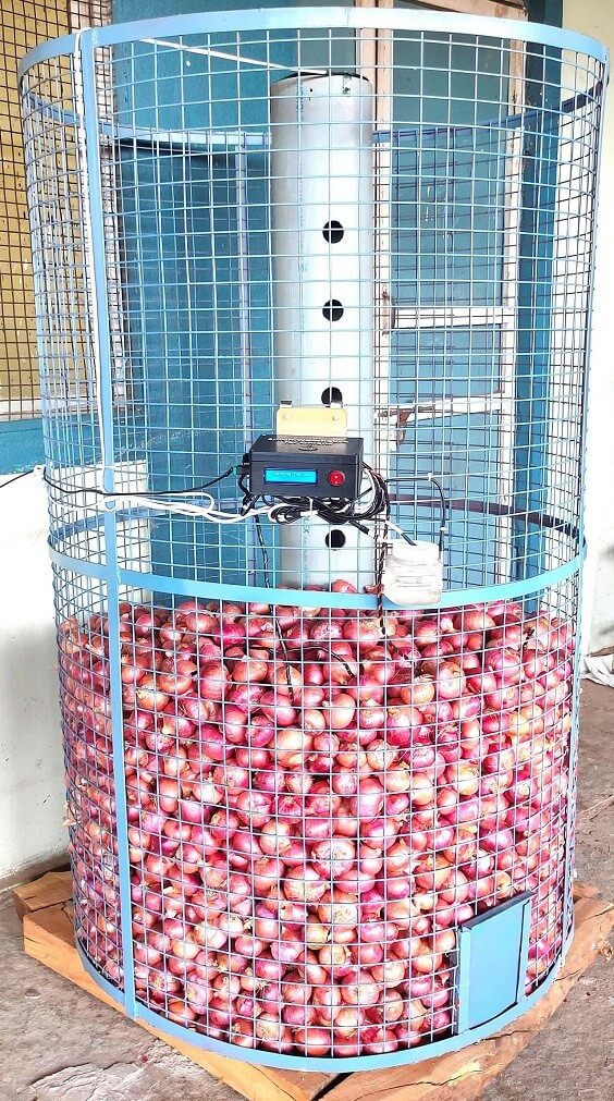
Following are the pictures of storage system designed and actual storage system I fabricated. I arranged these two pictures side-by-side to compare designed vs actual set-up.
 |
 |
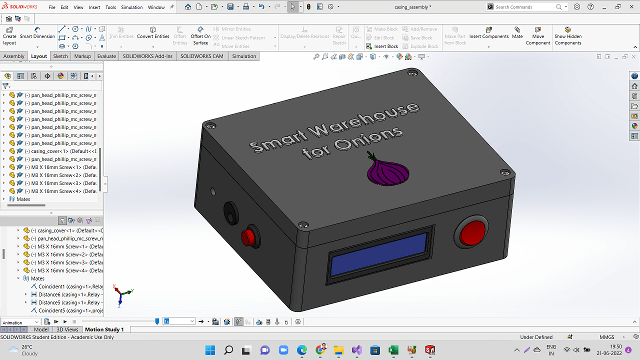
Following is a picture of the CAD model that I later designed for 3D printing the enclosure for electronics of the system.
 |
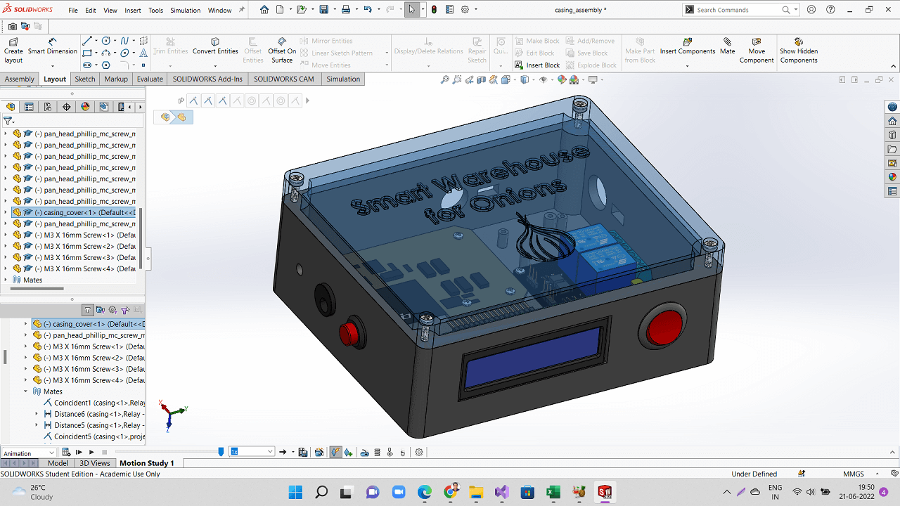 |
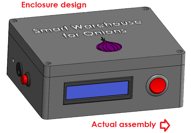
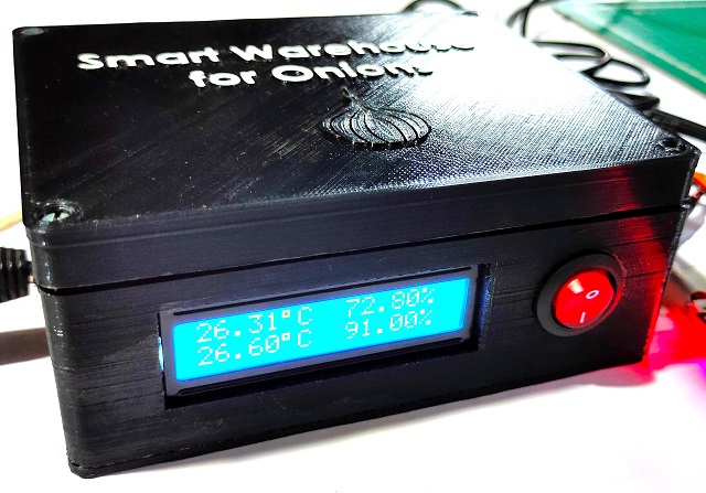
Following are the pictures of enclosure designed and actual enclosure I 3D printed and assembled. I arranged these two pictures side-by-side to compare designed vs actual assembly.
 |
 |
Click here to go back to the top
Electronics Design
Designing my final project board- 1st attempt
I designed my final project board in the week of output devices. I also milled and stuffed my final project board in that week only. I made an attempt to program this board. However, I could not program it because of some issues that I have explained below.
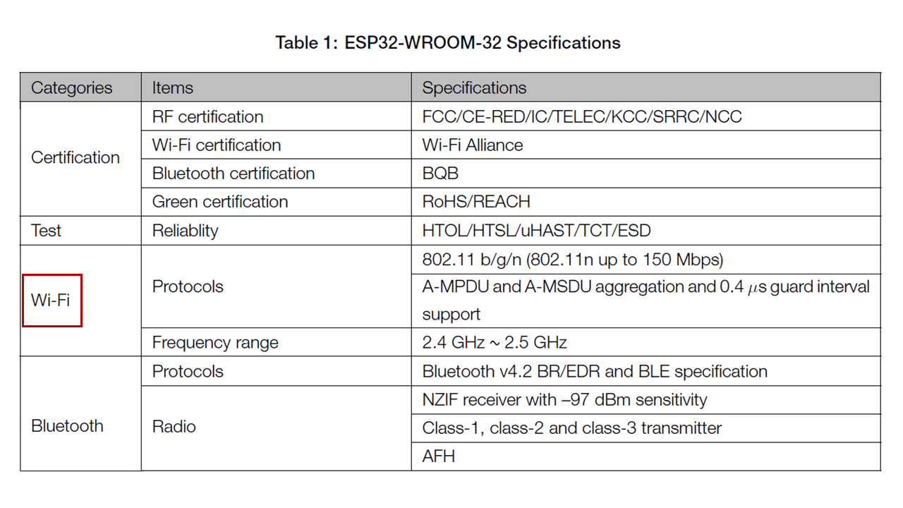
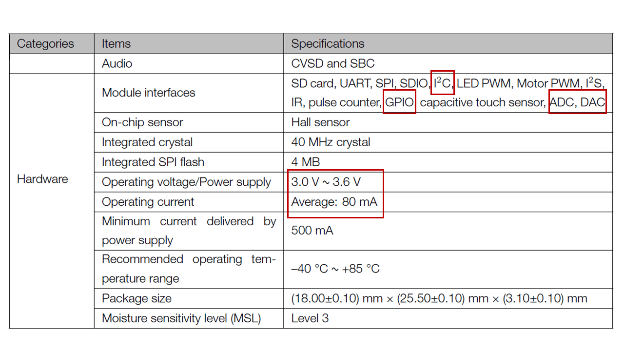
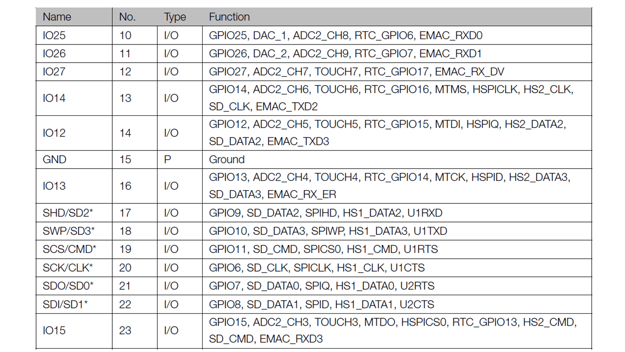
To begin designing my final project board, first I referred ESP32-WROOM-32 Data sheet to find out the pin-out of the IC to design my board. Below are the important specifications I looked in to while selecting ESP32-Wroom32 micro-controller for my final project board.
For more details on this, pls go to my 'Output Devices' assignment.
 |
 |
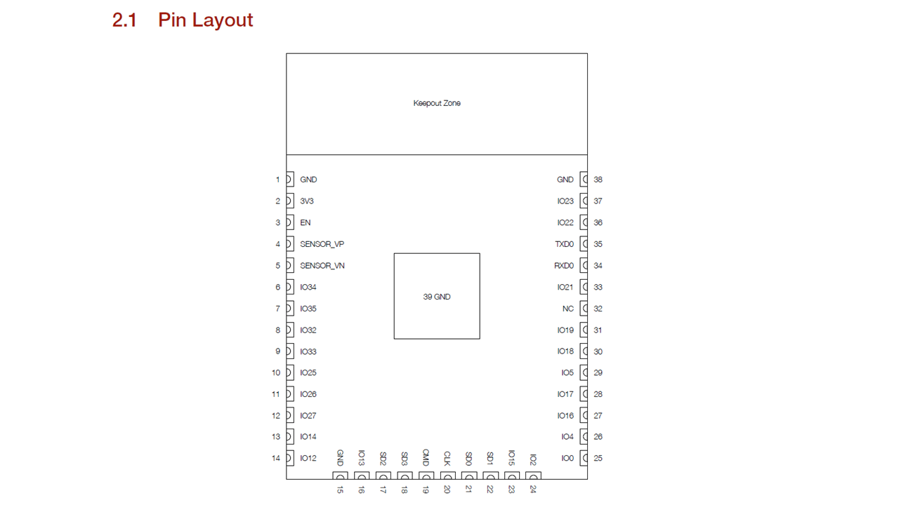
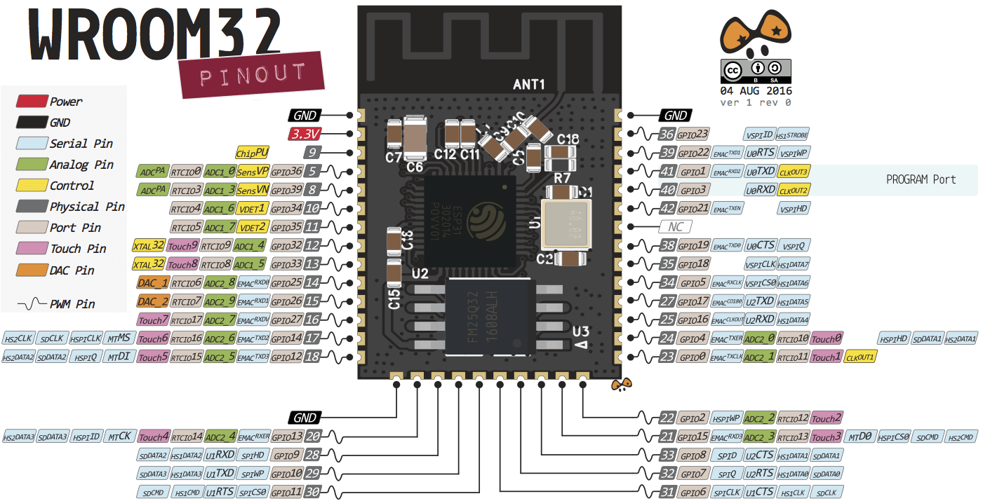
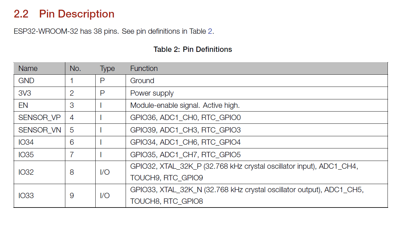
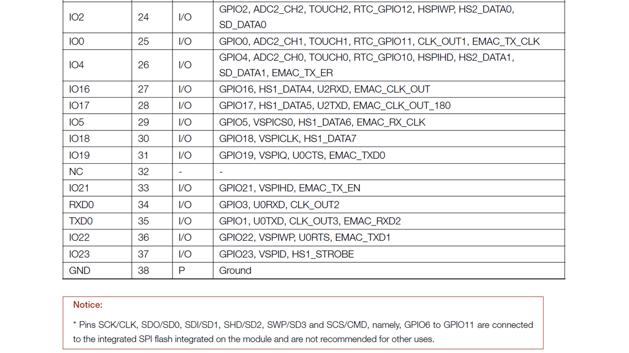
Below is the pin-out of ESP32-Wroom32. After understanding the pin-out and description of each pin from the datasheet, I chose pins for input and output devices that I will be connecting to my project board as shown below.
 |
 |
 |
 |
 |
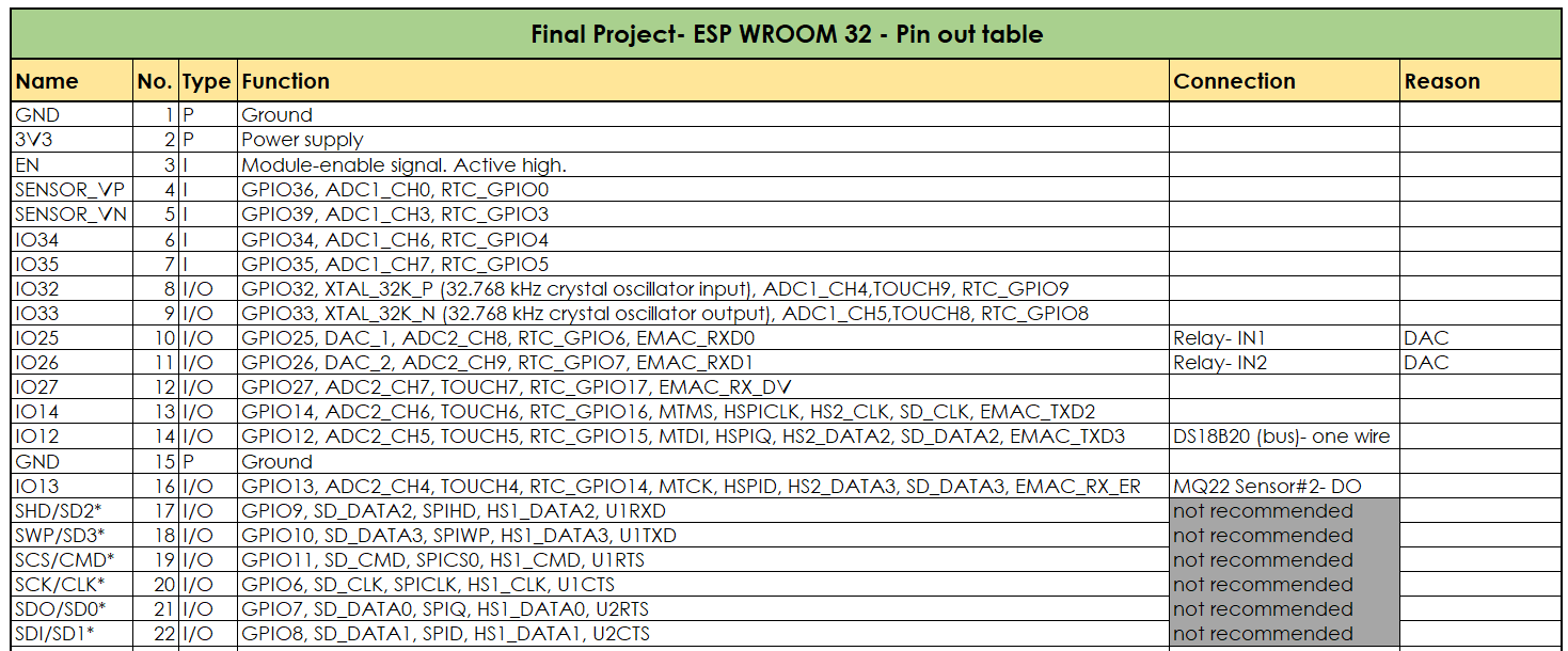
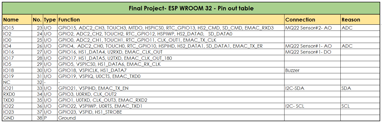
I then converted this table to an excel sheet for me to be able to map each pin to their respective input and output devices as shown below.
 |
 |
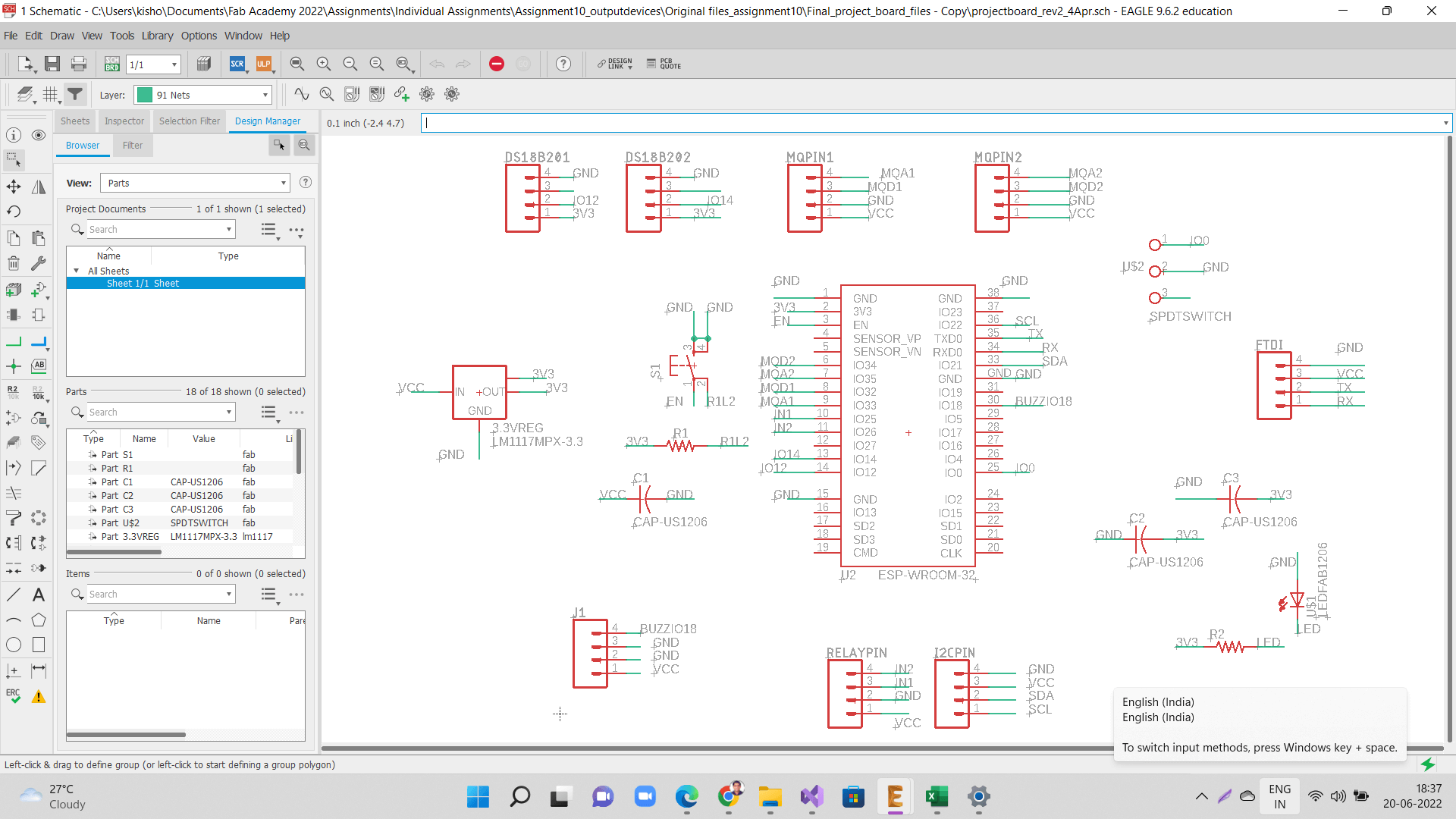
Using Eagle to design my final project board
I downloaded esp32 library for adding ESP32-Wroom-32 microcontroller IC to my shcematic and board as shown below. I referred this website to download the ESP32 library.
 |
 |
 |
 |
Click here to go back to the top
Electronics Production
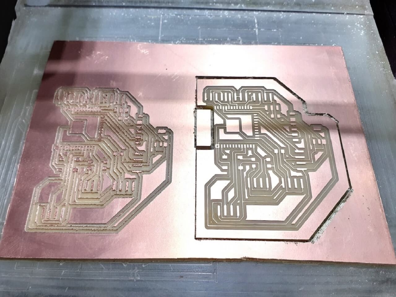
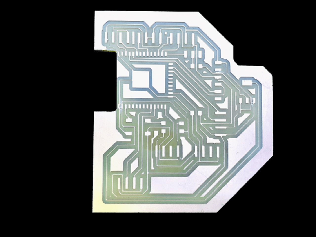
Milling my final project board:
For more details on this, pls go to my 'Output Devices' assignment.
 |
 |
 |
 |
 |
 |
 |
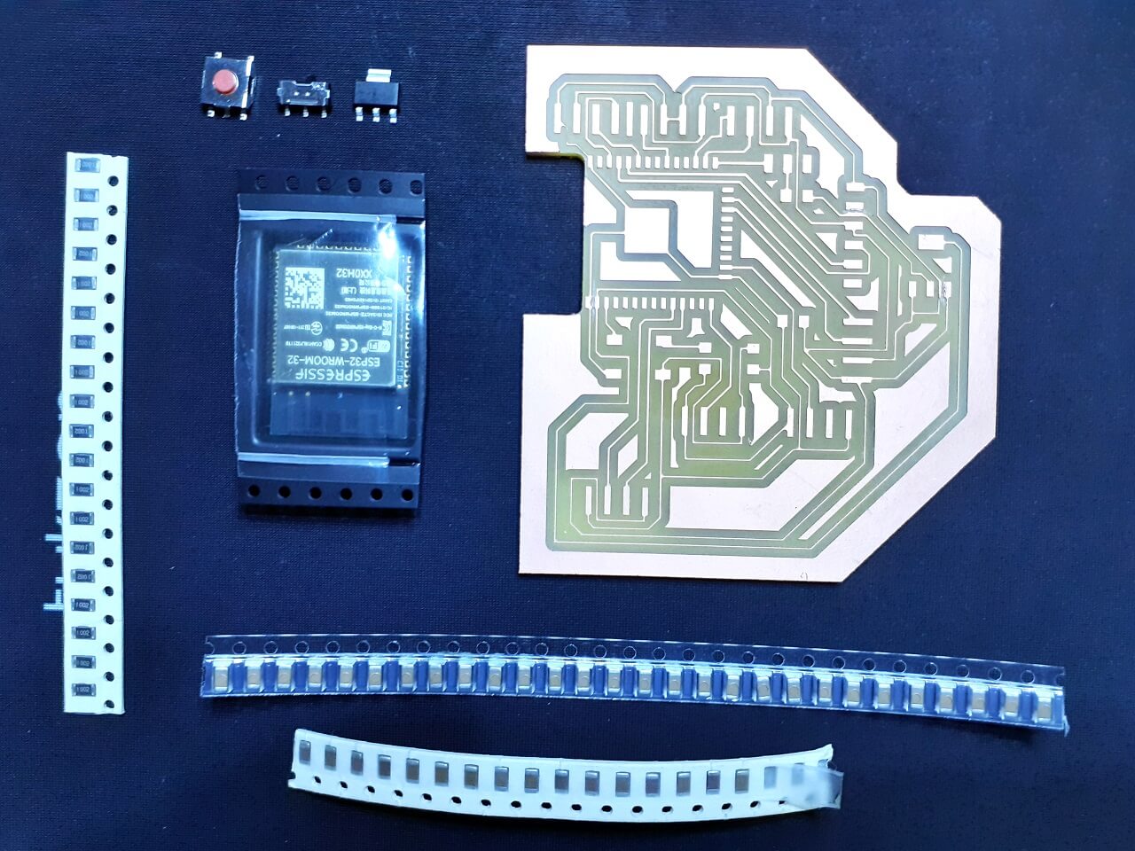
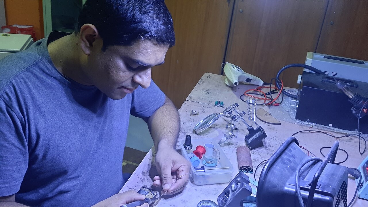
Stuffing my final project board:
Components Required for my Project board:
1. Resistor: 10K- 1 Qty
2. Capacitor: 1uF- 1 Qty
3. Capacitor: 10uF- 1 Qty
4. Capacitor: 0.1uF- 1 Qty
5. Push button (No)- 1 Qty
6. Sliding switch- 1 Qty
7. 3.3v voltage regulator (SMD)- 1 Qty
8. Microprocessor ESP32 Wroom- 1 Qty
9. FTDI Pin (6pin)- 1 QTY
10. 4x1 make header pins
 |
 |
 |
Issues with my final project board:
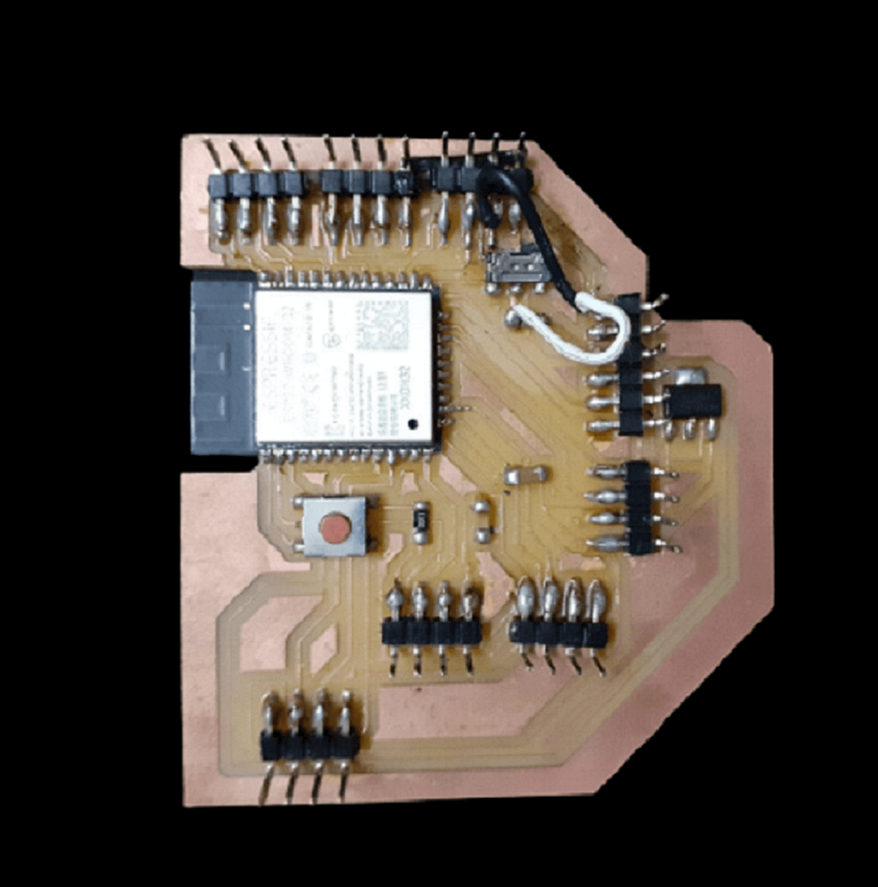
I designed, milled and stuffed my final project board. When I started to upload a basic program in to my board, it was giving timeout error. I checked connectivity between all connected points in the board and could not find much. I still kept facing the same timeout issue multiple times. So, my instructor Mr. Suhas and I decided to check the schematic one by one. We found out I did not make following connection in my schematic and there was not trace obviously.
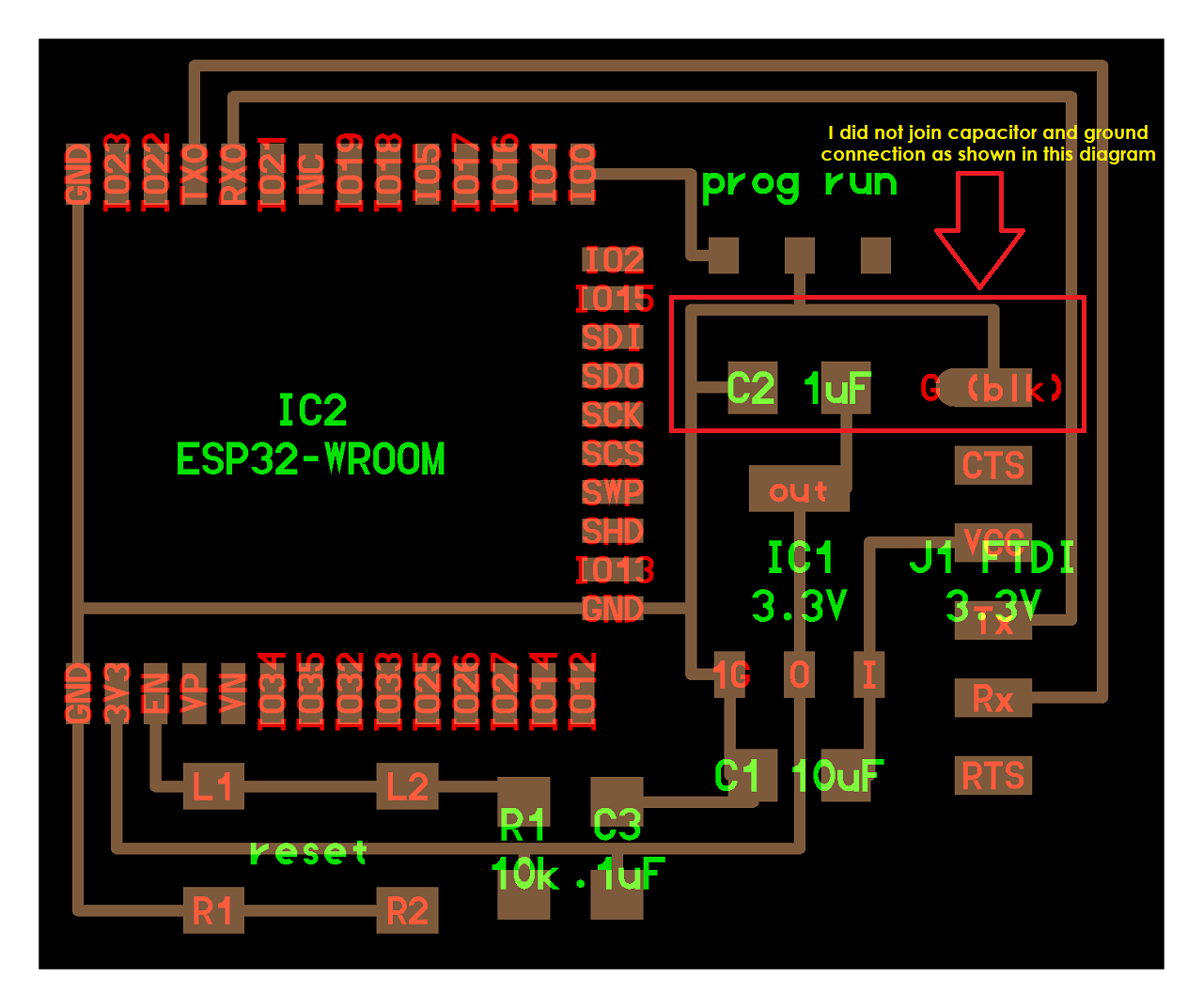 |
So, I had to place a jumper wire between GND and one end of capacitor that is connected to the sliding switch as shown below. My board started working and programs started uploading. However, I did not try using this board at all for any output device for this week because of the time crunch and machine week was my priority, so I stopped here and used my board in input devices week onwards. I have documented it in those assignments.
|
Click here to go back to the top
Input and output devices for final project
For more details on this, pls go to my 'Input Devices' assignment.
DS18B20 Temperature sensor
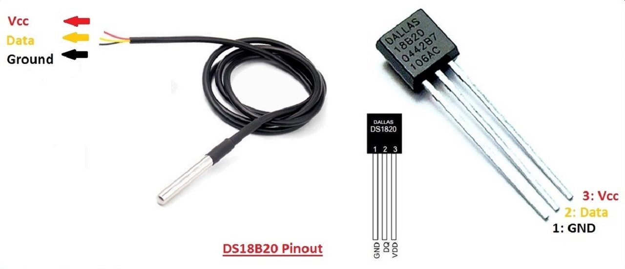
The DS18B20 is a 1-wire programmable Temperature sensor from maxim integrated. It is widely used to measure temperature in hard environments like in chemical solutions, mines or soil etc. The constriction of the sensor is rugged and also can be purchased with a waterproof option making the mounting process easy. It can measure a wide range of temperature from -55 Deg C to +125 Deg C with a decent accuracy of +/- 0.5 Deg C. Each sensor has a unique address and requires only one pin of the MCU to transfer data so it a very good choice for measuring temperature at multiple points without compromising much of your digital pins on the microcontroller. This is an advanced level protocol, where each sensor can be set with a 64-bit serial code which aids to control numerous sensors using a single pin of the microcontroller.
It supplies 9-bit to 12-bit readings of temperature. These values show the temperature of a particular device. The communication of this sensor can be done through a one-wire bus protocol which uses one data line to communicate with an inner microprocessor. Additionally, this sensor gets the power supply directly from the data line so that the need for an external power supply can be eliminated. The applications of the DS18B20 temperature sensor include industrial systems, consumer products, systems which are sensitive thermally, thermostatic controls, and thermometers.
DS18B20 Pin Configuration
-Pin1 (Ground): This pin is used to connect to the GND terminal of the circuit
-Pin2 (Vcc): This pin is used to give the power to the sensor which ranges from 3.3V or 5V
-Pin3 (Data): The data pin supplies the temperature value, which can communicate with the help of 1-wire method.
 |
DS18B20 Specifications
- This sensor is a programmable and it is a digital temperature sensor
- Communication of this sensor can be done with the help of a 1-Wire method
- Range of power supply is 3.0V - 5.5V
- The accuracy of this sensor is +/- 0.5 Deg C
- Output resolution ranges from 9-bit to 12-bit
- This sensor can be power-driven from the data line
- These are obtainable like SOP, To-92, and also as a waterproof sensor
- The temperature can be calculated from -55 Deg C to +125 Deg C
DS18B20 Datasheet Reference Source: Click here
MQ2 Gas sensor
Before I write more about MQ2 gas sensor, I will start with general working principle of gas sensors. Inside gas sensor, there is a chemi-resistor, which changes the resistance based on its sensing material. Following picture explains this functionality. Reference
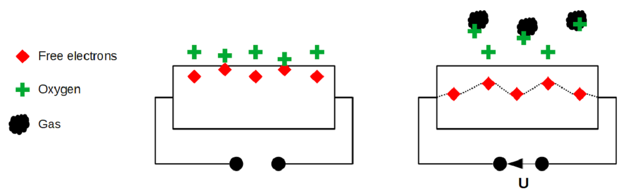 |
In most of the cases, the sensing material is tin dioxide (SnO2), which has free-electrons inside. Oxygen outside attracts these free electrons towards the surface of sensing material (picture on the left side above). when the oxygen is absorbed on the material, there are no free electrons available in the tin dioxide. This results in: without free electrons, there is no electrical current flow inside. Whereas, in an environment having toxic or combustible gases, this gas breaks the connection between the absorbed oxygen on the surface and the electrons (picture on the right side above). These released electrons are now free and they get back to their initial position, where they enable the current flow. Intensity of current flow depends on the amount of free electrons available in the SnO2, which is proportional to the concentration of toxic or combustible gases.
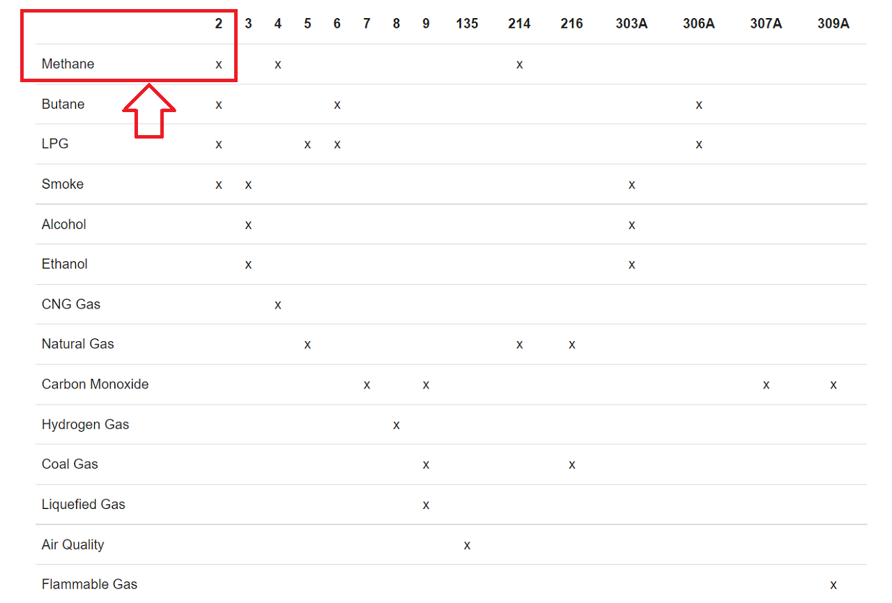
According to the Ohms law, a higher current flow results in a higher potential difference, which can be measured as output voltage on the analog output of the sensor, using a simple voltage divider network. Therefore, the concentrations of gas can be measured. The type of sensor is defined by the sensing material inside the sensor. Although some of the gas sensors are sensitive to multiple gases, the sensor can not identify which of the gases are in higher concentration. I referred the following table that gives us an overview about the different gas sensors that are available and what gasses they are able to detect. Since I want to detect methase gas, I selected MQ2 gas sensor for my project.
 |
Before I start using the MQ2 gas sensor for my project, I needed to know more about this sensor, the whole module along with all other electronic components. Therefore, I went through the technical datasheet of the entire module and how the MQ2 gas sensor is measuring the gas concentration. Then, I went through the electronic components on the senor module along with its pinout.
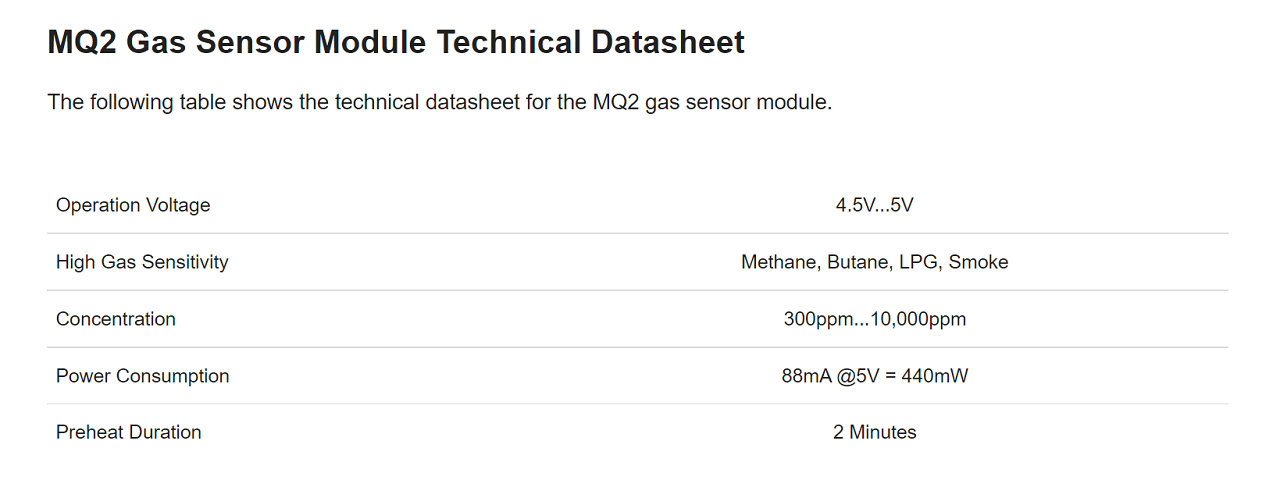 |
The operating voltage of MQ2 gas sensor is between 4.5V and 5V. This sensor is also used as heater for the surface of the SnO2. Therefore, the microcontroller I am going use in my project (which is ESP32) needs to provide a stable 5V output. I have to power my ESP32 board via USB or an external power supply to get an 5V output. The MQ2 gas sensor is sensitive to LPG, methane, butane and smoke in general. These gases can be measured in concentrations between 300 ppm and 10,000 ppm. Because it takes some time until the surface is hot, the MQ2 gas sensor has a preheat duration of around 2 minutes and has a current consumption of 88mA also during the preheat duration. With a 5V supply voltage, the MQ2 gas sensor has a power consumption of 440mW.
MQ2 Pin Configuration
The following picture below shows the back side of the MQ2 gas sensor module board.
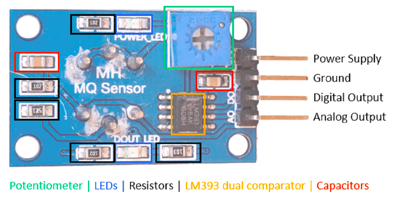 |
This module consists of the following electronic parts:
- 4 output pins that connect the gas sensor to a microcontroller:
1. A0: Analog pin to transfer an analog signal.
2. GND: Ground to connect the gas sensor to ground with the microcontroller.
3. VCC: Pin for the 5V operation voltage
4. D0: Digital output based on a predefined threshold through the potentiometer and the operation voltage of the microcontroller.
- 2. Potentiometer to define a threshold for the digital output pin.
- 2 LEDs to indicate that the module is operating (POWER_LED) and to indicate the status of the digital pin (DOUT_LED).
- 5 Resistors to prevent LEDs for too high voltages and to operate as voltage dividers.
- LM393 dual comparator to compare the signal created by the MQ2 gas sensor with the predefined value through the potentiometer and to control the status of the LED that indicates the status of the digital output.
- 2 Capacitors to filter the voltage and stabilize the input and output.
Functionality of the MQ2 Gas Sensor Module
The resistance of the MQ2 gas sensor decreases as the gas concentration that is measured increases. When the gas concentration increases, the voltage across the MQ2 sensor decreases because of the decrease of resistance (V=R*I). Because the voltage between VCC and GND needs to be the same, the voltage across the resistance increases and thus the potential on the point, where the analog value is measured. The analog sensor value increases due to the increase of gas concentration.
MQ2 Datasheet Reference Source: Click here
Connectiong DS18B20 temperature to my board
For more details on this, pls go to my 'Input Devices' assignment.
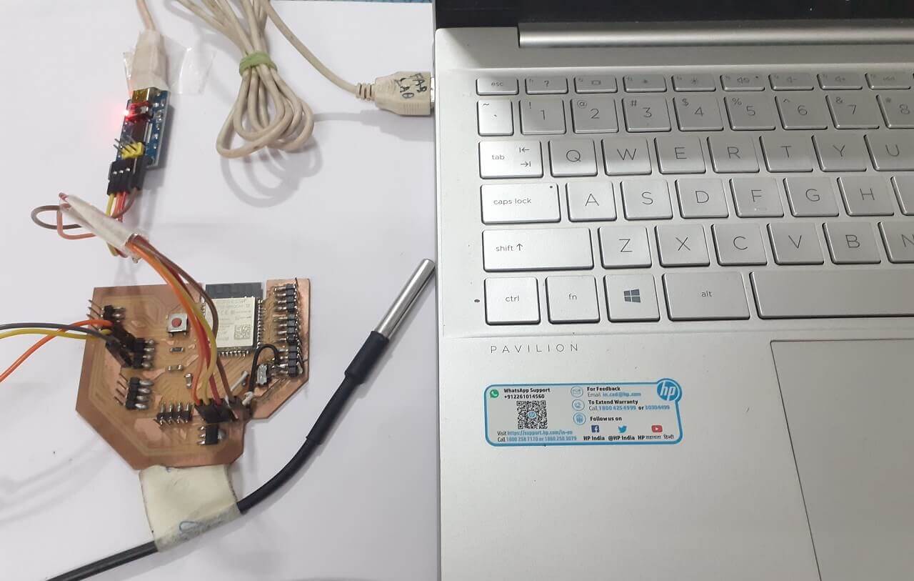
For the requirement of my project, I connected DB18B20 temperature sensor to my project board as shown below. I programmed my board and measured temperature readings. This was done primarily to test my board, my program and the input device if it is working the way it is supposed to be.
 |
Click here to see/copy the DS18B20 basic program or download sketch from the cloud screen below.
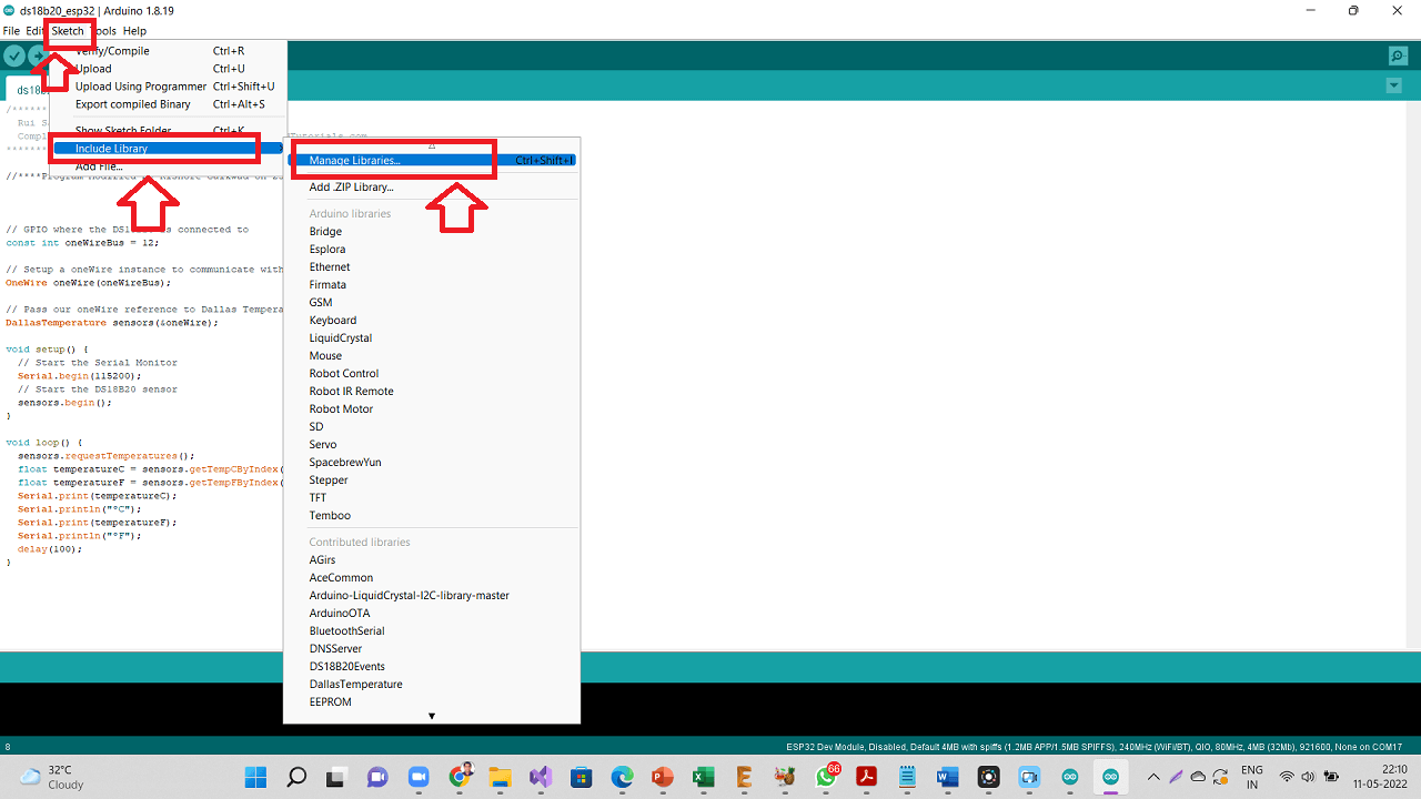
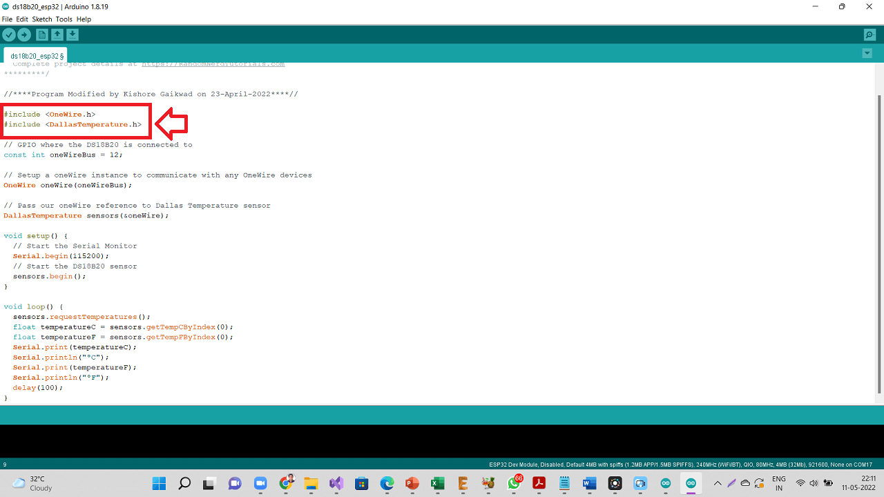
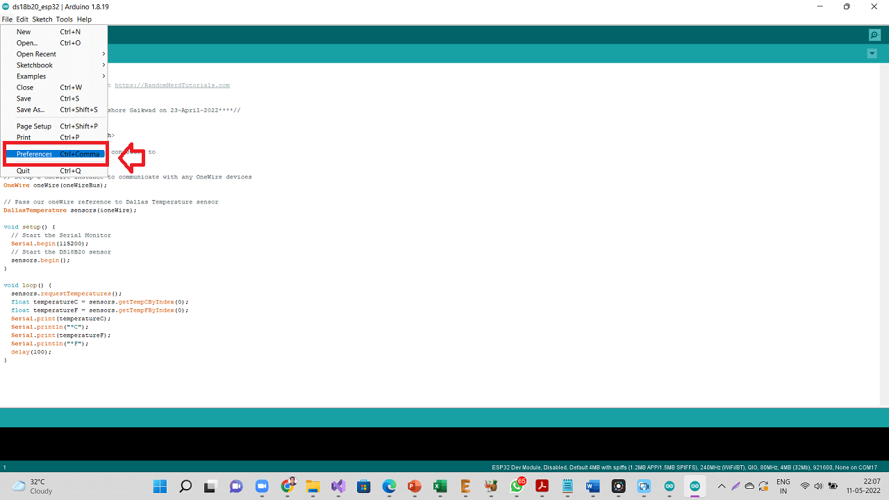
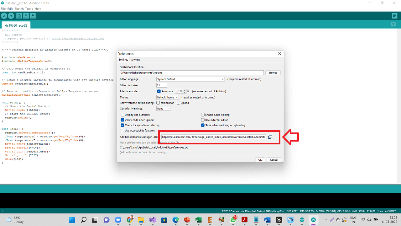
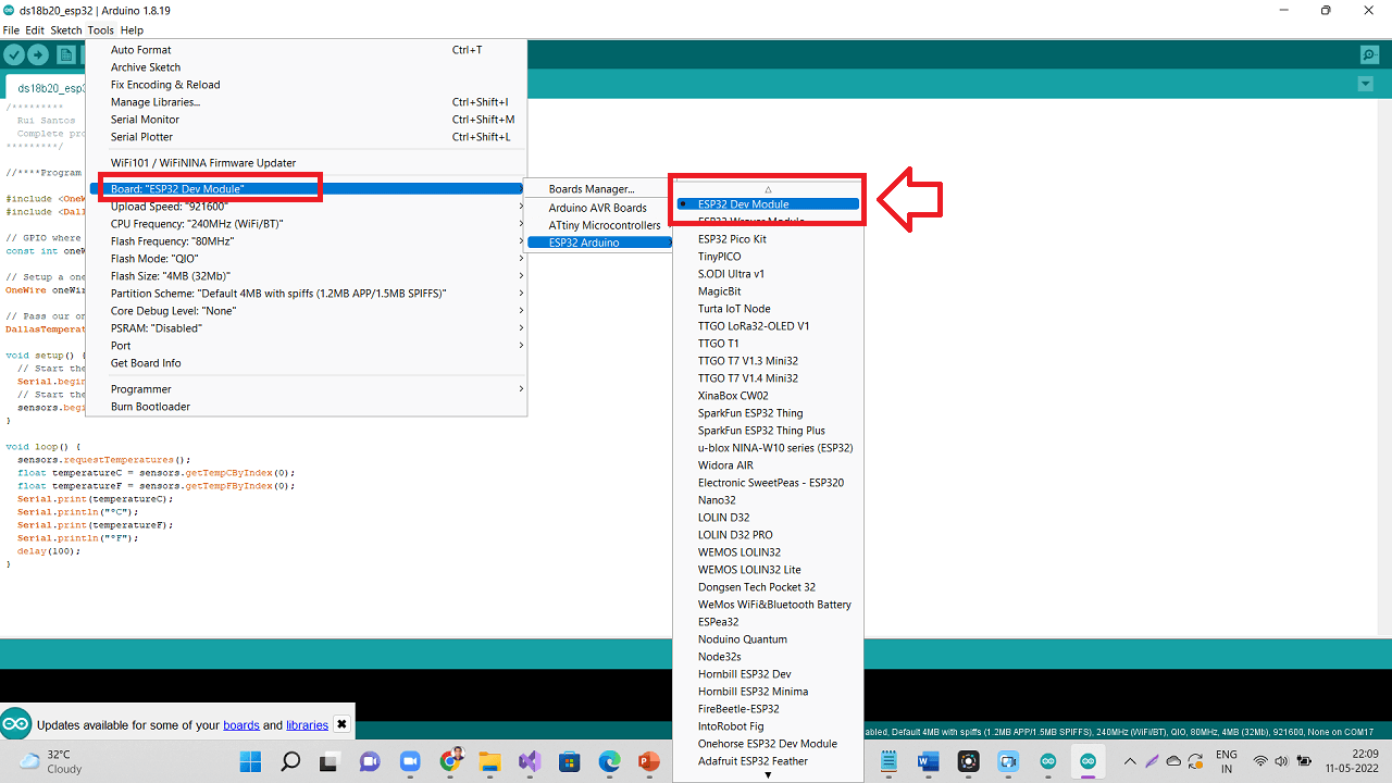
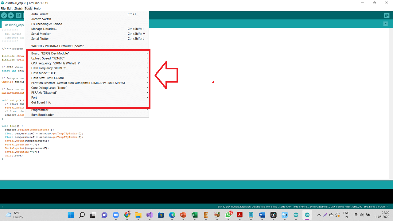
Following are the settings done in Arduino IDE. I also installed onewire.h and DallasTemperature.h libraries as shown below.
On Arduino IDE, Navigate to Sketch --> Include Library --> Manage Libraries
 |
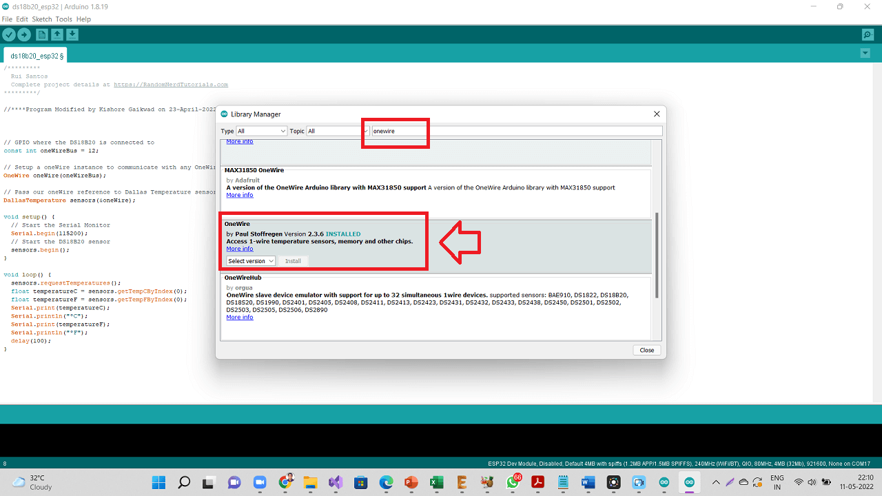
Type "OneWire" on the search box, then look for the OneWire library by Paul Stoffregen. Click Install button to install OneWire library.
 |
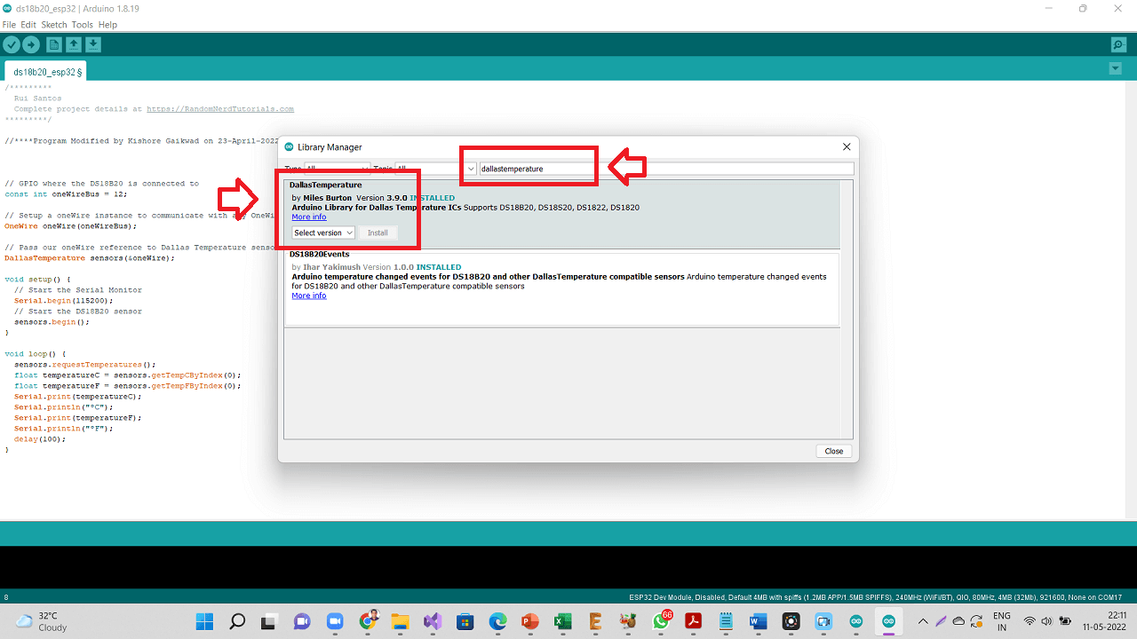
Type "dallastemperature" on the search box, then look for the "DallasTemperature" library by Miles Burton. Click Install button to install DallasTemperature library.
 |
 |
 |
 |
 |
 |
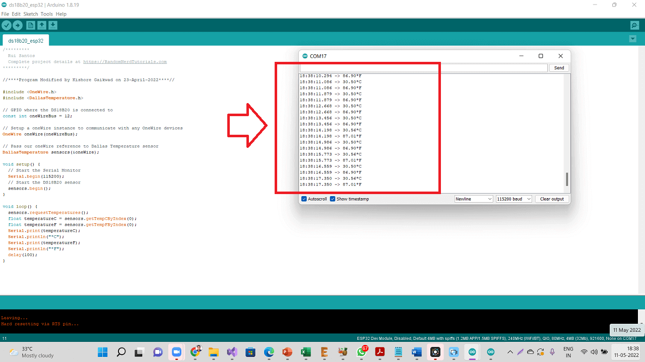
Following are the Temperature readings seen in Serial monitor.
 |
Connectiong DS18B20 temperature sensor and a relay to my board
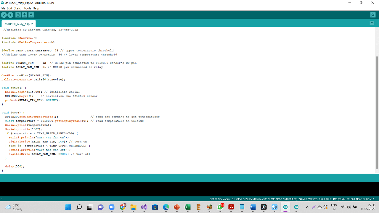
For the requirement of my final project, I connected one DS18B20 temperature sensor as an input device and a relay connected to an AC bulb as an output device to my final project board. I am going to connect an exhaust fan to the relay. However, for to check if the relay is working with the program and also to meet the purpose of this and previous assignment, I connected relay to AC bulb.
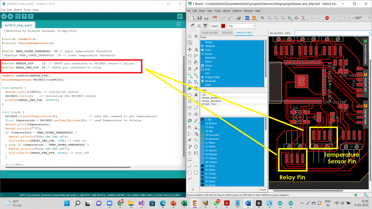 |
Click here to see/copy the DS18B20 and Relay program or download sketch from the cloud screen below.
 |
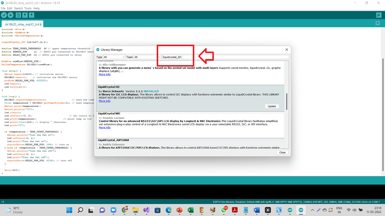
I also added an LCD screen as an output device to my board. I added "LiquidCrystal_I2C" library as shown below.
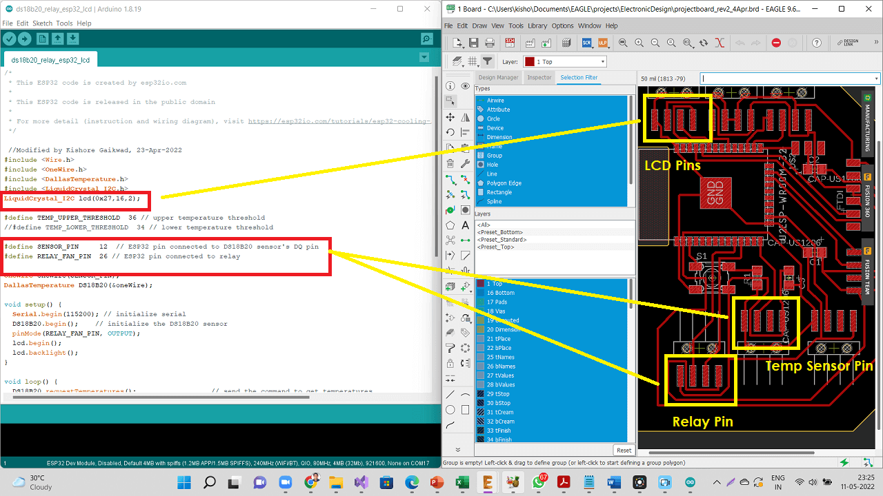 |
 |
Click here to see/copy the DS18B20 and Relay program with LCD added or download sketch from the cloud screen below.
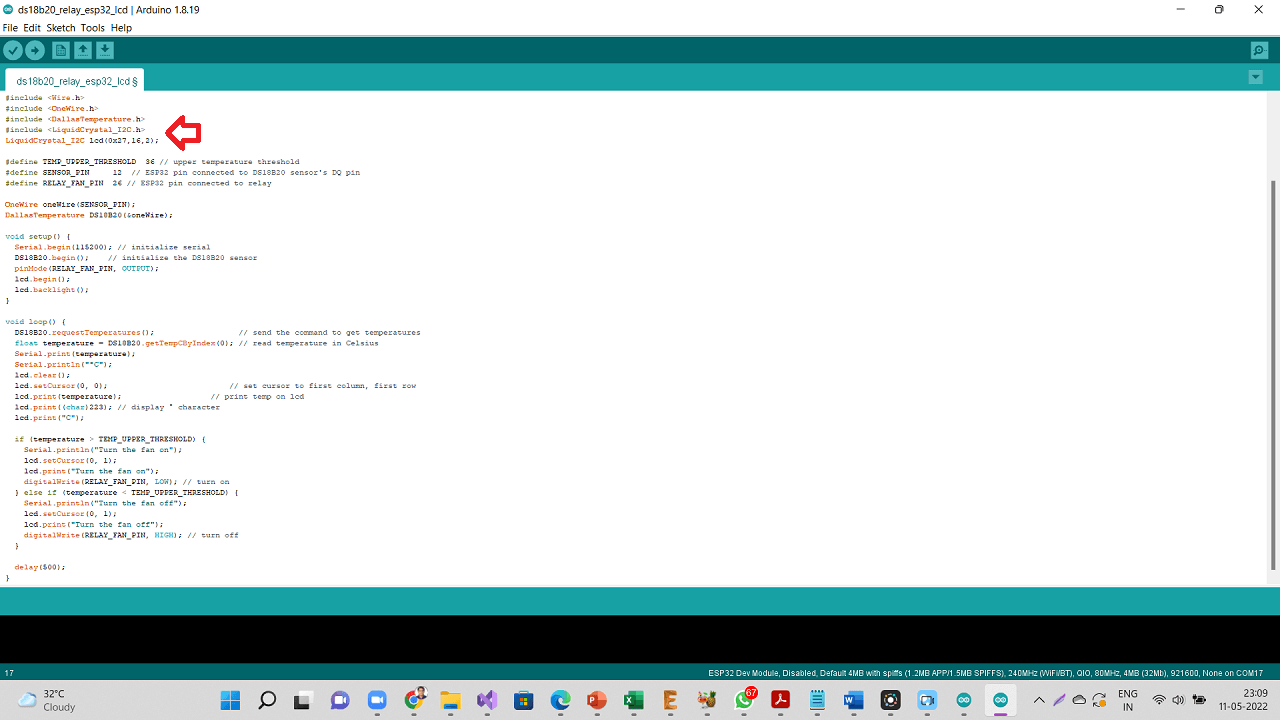 |
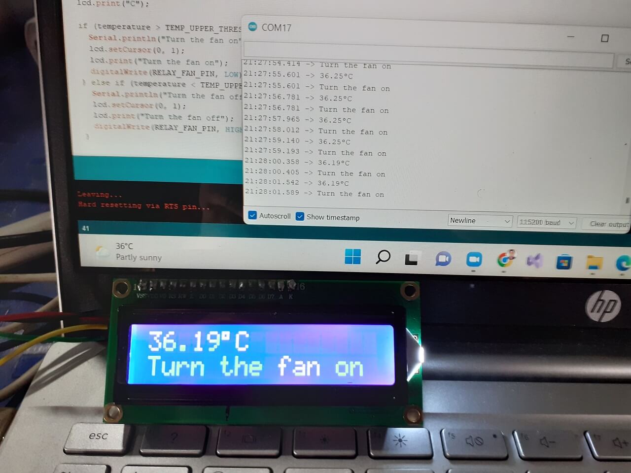
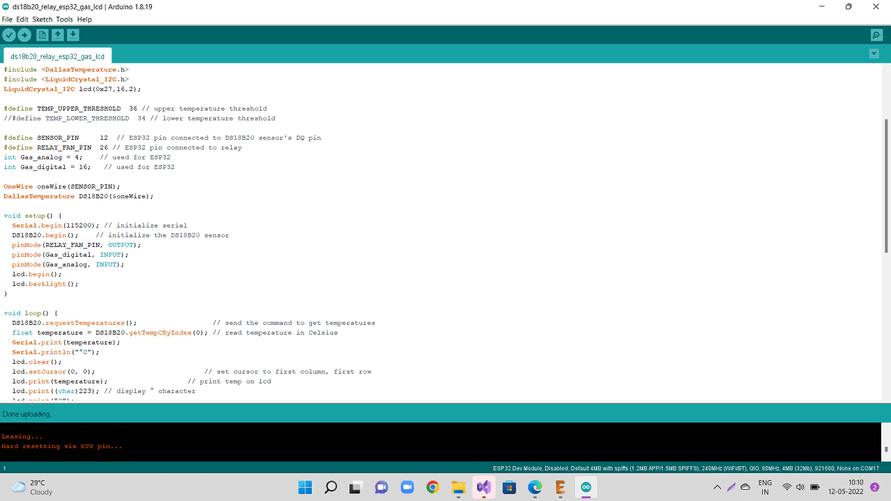
I have added an IF condition to the program. When the temperature reading from the sensor is above 36 Deg Celcius, the relay is going to be switched ON and it switches OFF below 36 Deg C.
 |
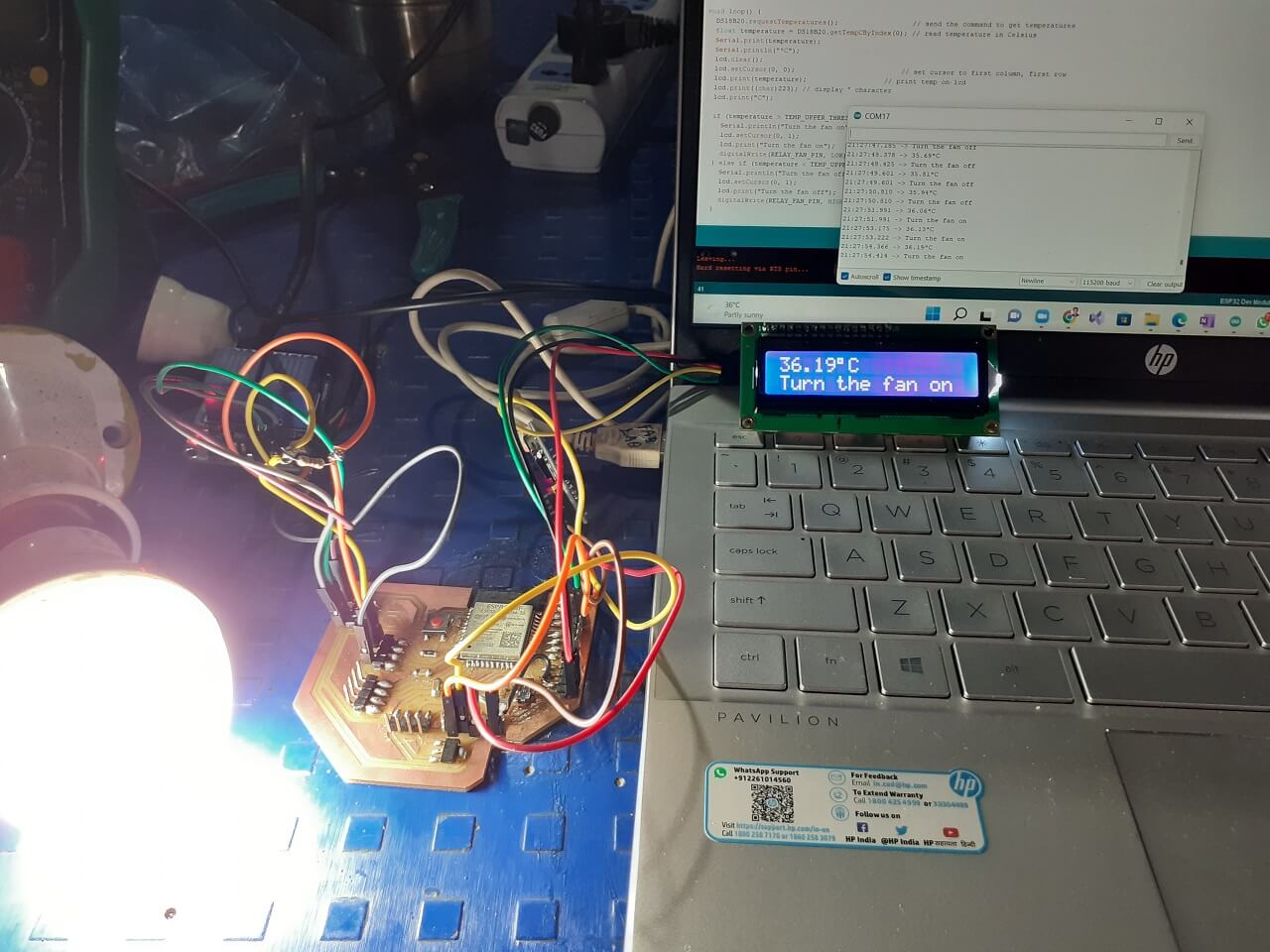 |
Video: Connecting and testing DS18B20 temperature sensor:
Connectiong MQ2 Gas sensor to my board
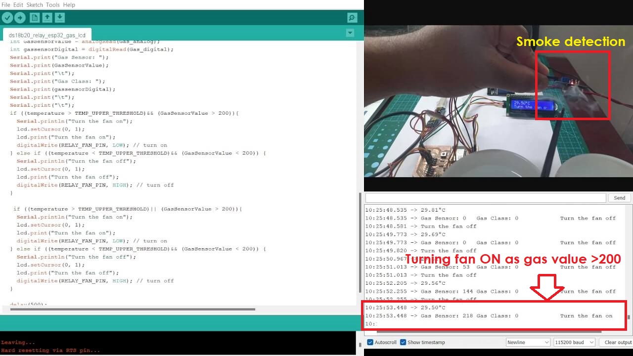
For the requirement of my final project, I also wanted to connect one MQ2 gas sensor as an input device to measure the methane gas concentration around the onions. As the onions in warehouse get rotten, they emit methane. So, I decided to connect on MQ2 gas sensor, which detects methane. As the methase gas level goes beyond a threshold value, the microcontroller will turn the relay and the exhaust fan ON. I therefore, first tried connecting MQ2 gas sensor along with the LCD display as shown below.
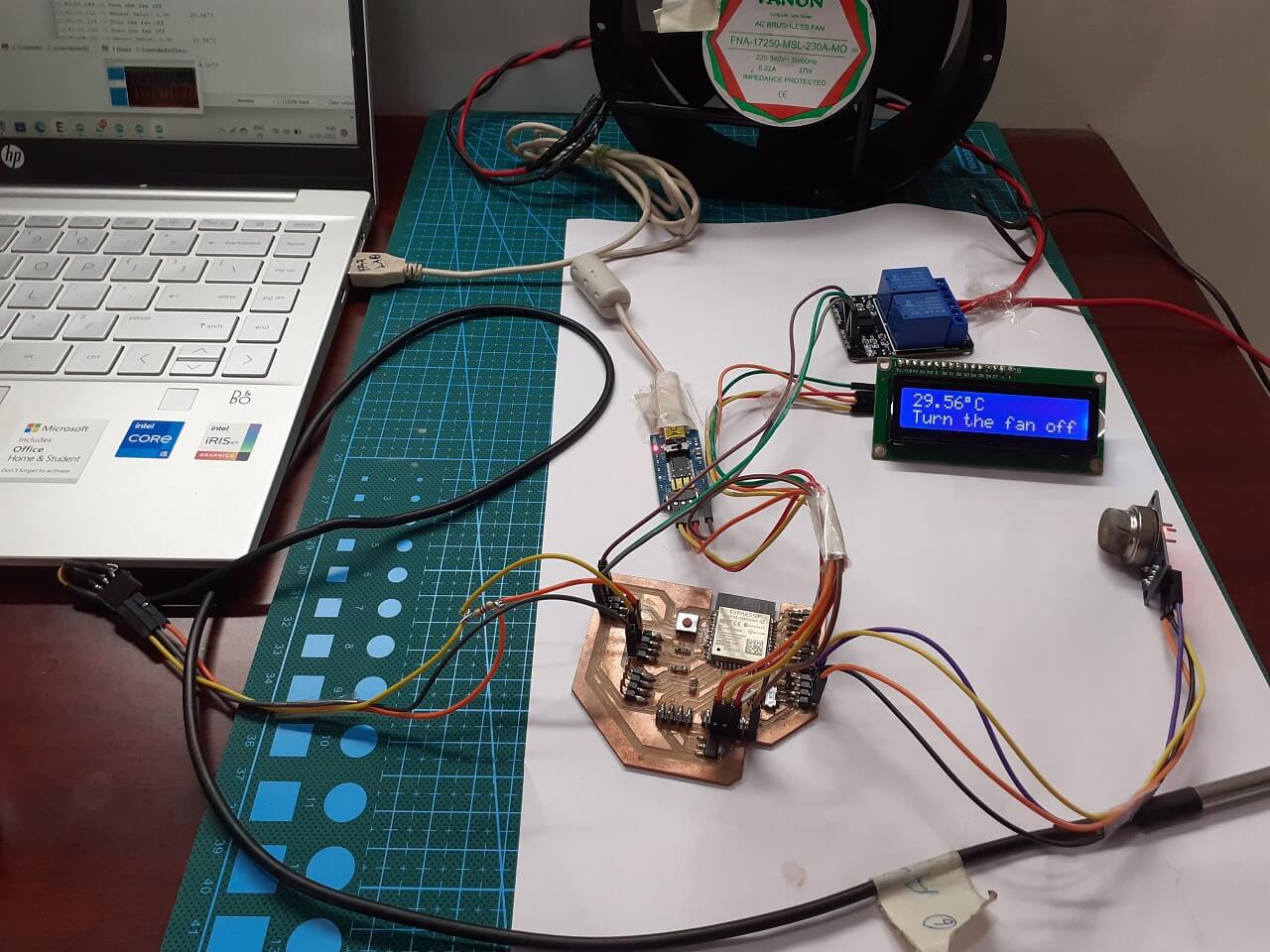 |
Click here to see/copy the DS18B20, MQ2 sensor, LCD and Relay program or download sketch from the cloud screen below.
 |
 |
 |
Click here to go back to the top
Networking and Communications for final project
Connecting wifi to collect Temperature sensor values and publishing through Thingspeak:
For more details on this, pls go to my 'Networking and Communications' assignment.
In my final project, I am connecting DS18B20 temperature sensor and a relay to my board. I wanted to collect temperature readings by the sensor and control relay connected to the exhaust fan. I also wanted to publish these readings over thingspeak IoT analytics platform over cloud.
 |
Click here to see/copy program for communication through wifi or download sketch from the cloud screen below.
Code explaination:
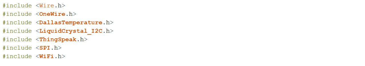
I first included the necessary libraries at the beginning of the code, e.g. wire library for I2C device communication (LCD in my case), the OneWire and DallasTemperature for the DS18B20 temperature sensor, LiquidCrystal_I2C for I2C serial interface adapter used with 16x2 LCD screen, ThingSpeak library for communicating data to ThingSpeak cloud and wifi library for using wifi.
 |
Then, I declared a LiquidCrystal 12C object with 12C address, the number of columns, the number of rows (16 columns and 2 rows in my case)
 |
I defined SSID and password for my wifi network along with Channel ID and Secret Write API key for my ThingSpeak IoT channel.
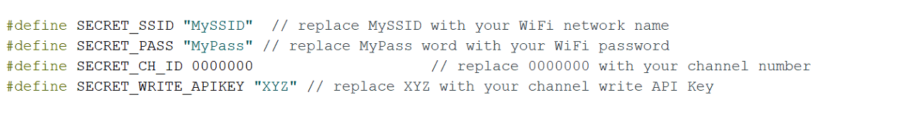 |
After that, I created two char variable called char ssid[] and char pass[] to save the SSID and password.
 |
Through WiFiClient, I created a client that can connect to a specified internet IP address and port as defined in client. int keyIndex = 0; is network key Index number (needed only for WEP).
 |
I also created one unsigned long variables (extended size variables) for storing my Thingspeak Channel ID along with const char* to declare Write API key for my channel.
 |
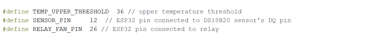
I defined upper threshold temperature for my project above, which the exhaust fans will be switched ON. I defined GPIO 12 for onewire bus for DS18B20 sensor and GPIO 26 for Relay pin.
 |
After defining the DS18B20 sensor pin I created objects OneWire and DallaTemperature to make it work.
 |
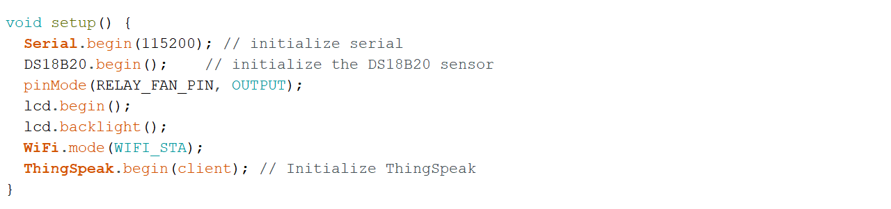
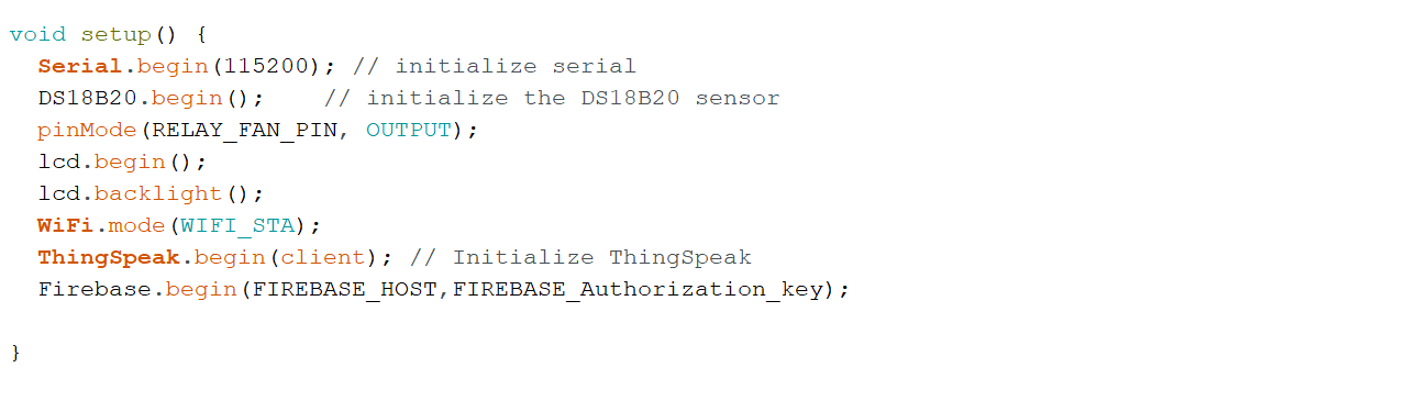
In the setup(), set the RelayPin as an output. Then, added lcd.begin() to initialize the interface to the LCD screen, DS18B20.begin() function to search for connected sensors on the bus and sets bit resolution (12 bits) for each one of them. Also added lcd.backlight() function to start the LCD backlight. WiFi.mode(WIFI_STA) sets up station mode for ESP32 to connect to an access poin. Lastly added ThingSpeak.begin(client) to initialize ThingSpeak.
 |
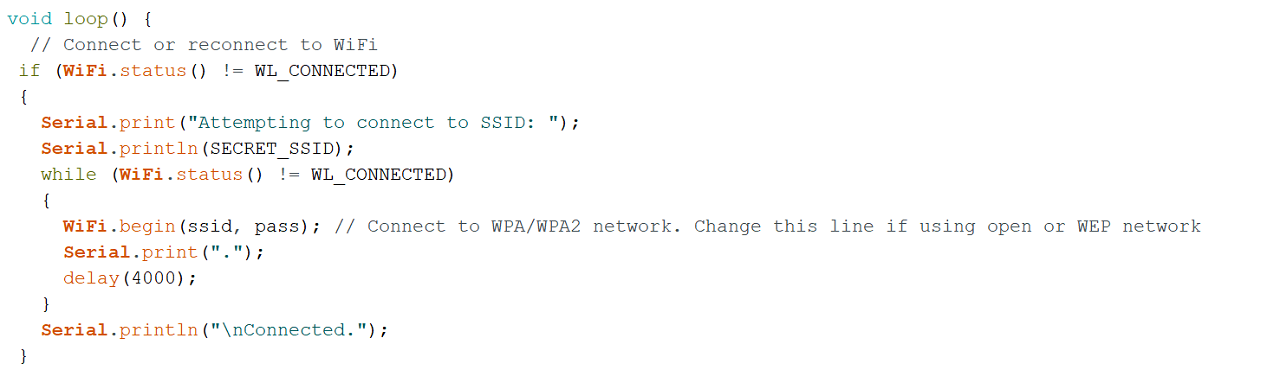
In the loop(), wifi connection is made. Connecting to a Wi-Fi network can take a while, so we usually add a while loop that keeps checking if the connection was already established by using WiFi.status(). When the connection is successfully established, it returns WL_CONNECTED. To get the status of the Wi-Fi connection, I used WiFi.status(). This returns WL_CONNECTED value, when it is connected to a WiFi network. I then used WiFi.begin() to connect to a network.
 |
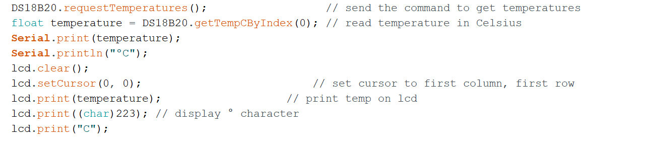
DS18B20.requestTemperatures() function is used to send command for all sensors on the bus to perform a temperature conversion. Defined 'temperature' as a float. DS18B20.getTempCByIndex(0) function reads and returns temperature reading from the sensor. deviceIndex is nothing but the location of the sensor on the bus. If you are using only one DS18B20 on the bus, set it to 0. The additional ones will be 1, 2, 3 and so on after the first one as 0.
Then, lcd.setCursor(0, 0) Move cursor to the desired position (column_index, row_index), (0, 0) in this case. lcd.print(temperature) prints Temperature value read by the sensor.
 |
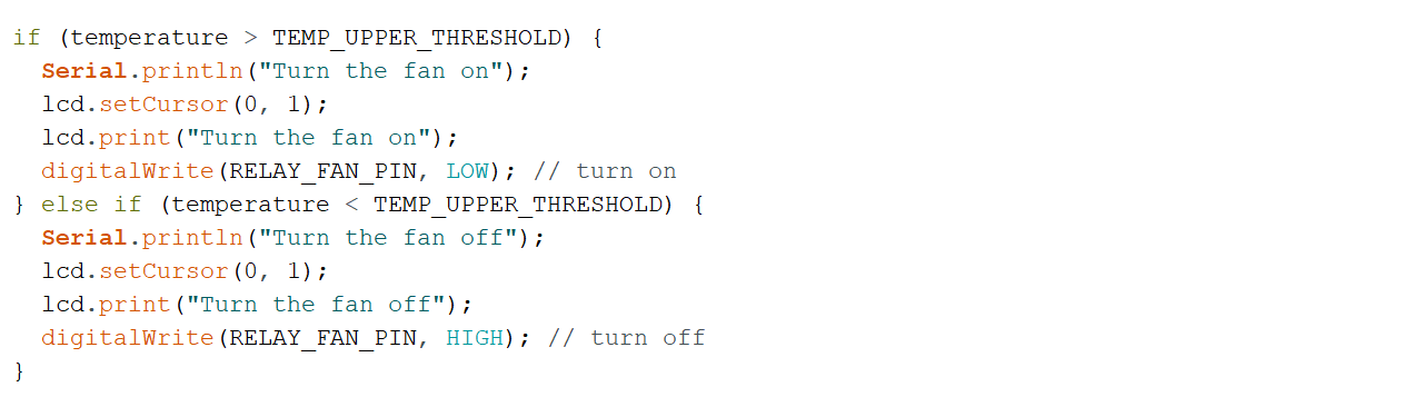
The if statement in the code reads the temperature values and takes appropriate action with regard to the Relay pin. The logic works like this, if the temperature goes above the upper threshold value defined earlier in the code, the microcontroller turn relay's GPIO pin HIGH and LOW if it is below the upper threshold value.
 |
Lastly, I defined an int x to push the temperature values on to the field#1 I have created on my ThingSpeak channel. The channel ID and myWriteAPIKey are already declared in the code above.
 |
Wifi code working and publishing data to ThingSpeak channel:
For more details on this, pls go to my 'Networking and Communications' assignment.
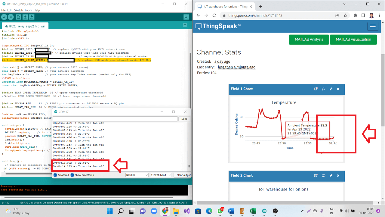
This is how the code is working and publishing temperature data to my ThingSpeak channel
|
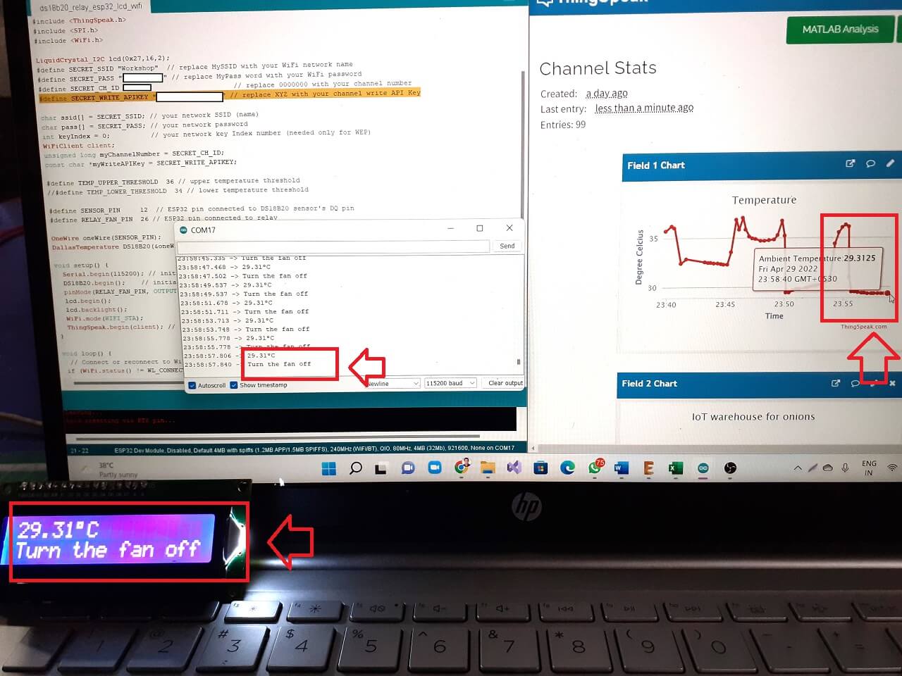 |
The picture below is from the next part of my project, where I have added more than one sensor on onewire bus and also have started collecting the humidity values. I just added that picture though humidity data capturing was not a part of this code and assignment.
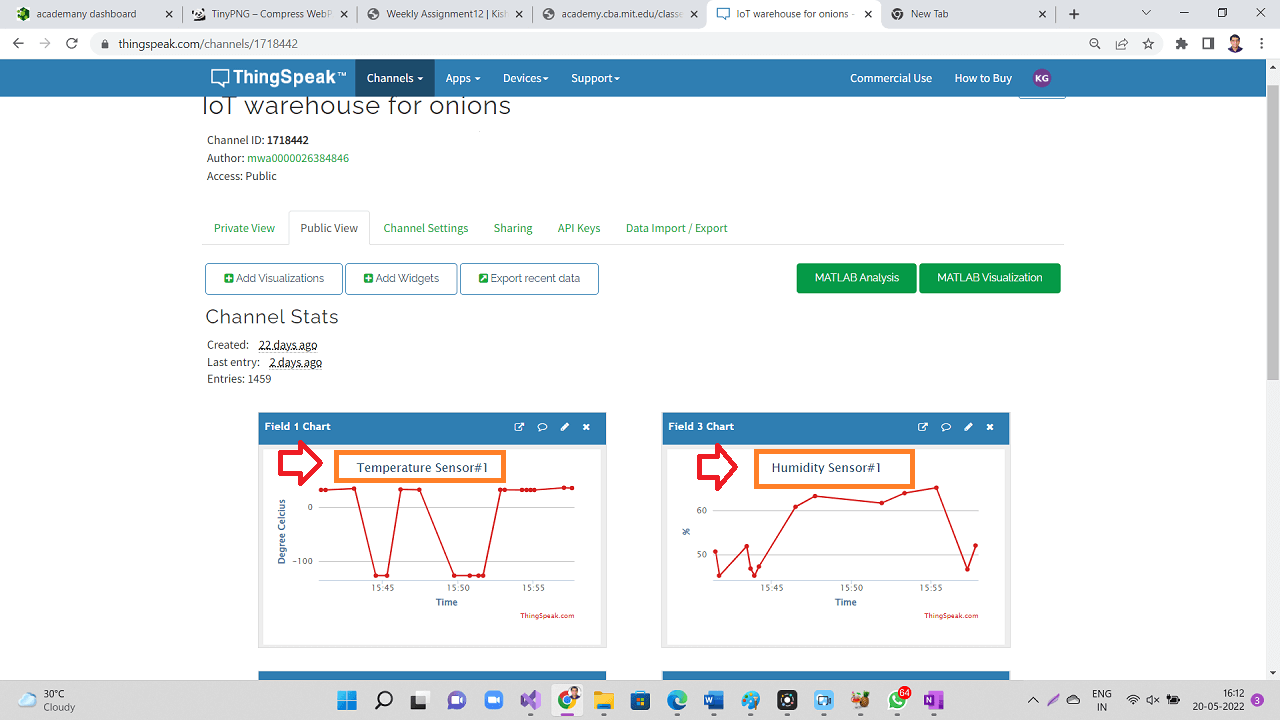 |
Failure: Issues indentified with MQ2 gas sensor and wifi
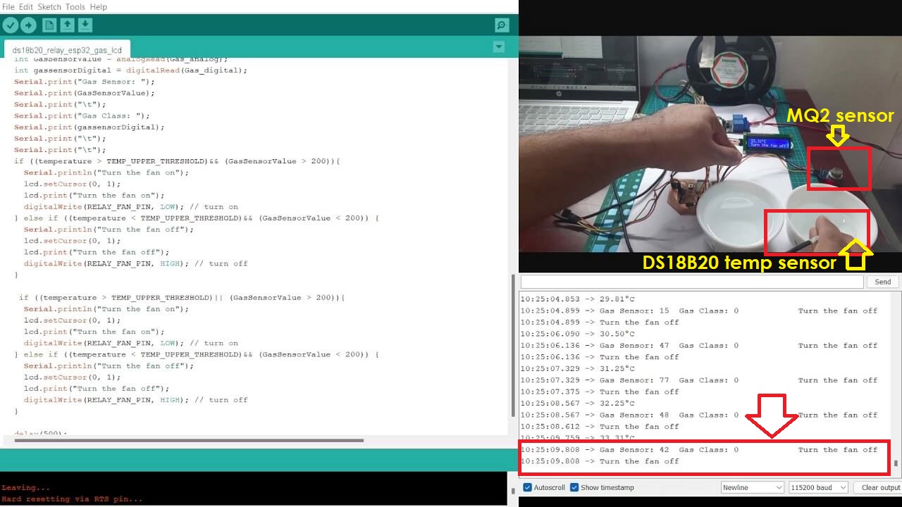
As mentioned earlier, I was able to connect MQ2 gas sensor that I am going to use to detect the level of methane released from the rotten onions in the storage. I was able to test the connection and working of this gas sensor along with DS18B20 temperature sensor, relay and LCD. The connections, code and logic worked perfectly well as to control the relay based on both or either of the values of temperature and gas concentration.
However, as I started to make that code work with wifi for this week's assignment, I was having problems with getting gas sensor's analog values. I initially thought it was a problem with my code. I went through every single line of code at least 5-6 times and verified if I made any mistakes while adding wifi code to my earlier program I wrote till I incorporated gas sensor with temperature sensor and other output devices. However, there was no single mistake in the code. The code was also able to get compiled.
Then, I started looking in to the wiring and connections. That too was perfectly ok. So, what was the problem? I kept wondering and I started troubleshooting everything, which took more that 4-5 hours. I could not do any other work that day. I also looked for any help online and I could not find any solution till late in the evening and I got more frustrated.
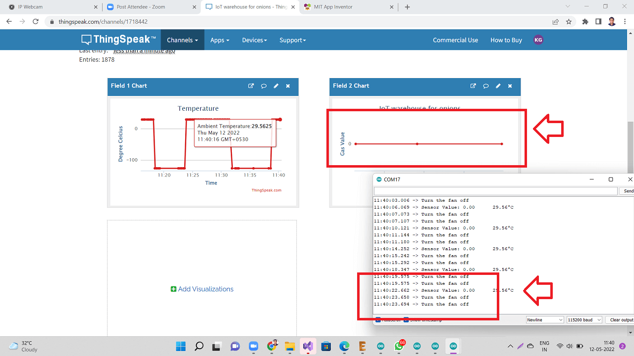
The second image below shows that the serial monitor of arduino IDE was showing temperature readings but the gas sensor values were 0 always.
Click here to see/copy program for MQ2+DS18B20+wifi program or download sketch from the cloud screen below.
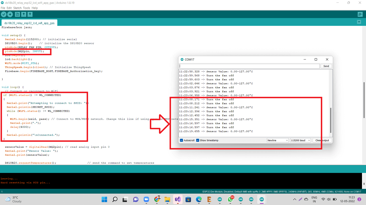 |
These two field values are also reflected on my ThingSpeak IoT channel and you can see the Gas sensor values are 0 there too.
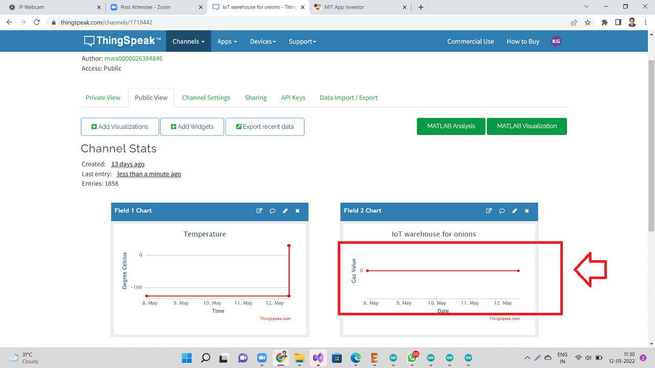 |
 |
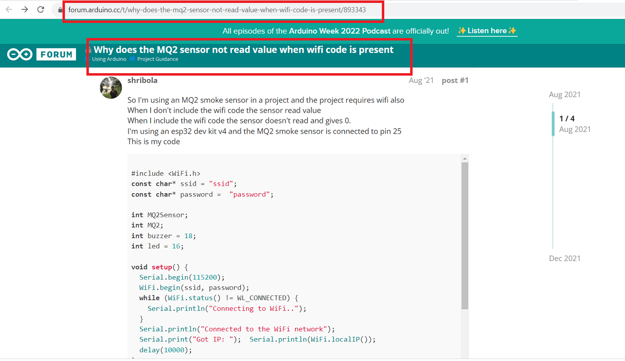
Then I found online about this issue, someone had already faced very similar issue before. They too were not getting MQ2 analog values when connected to wifi, otherwise they too were getting readings. Click here to read more about this question on the arduino forum.
 |
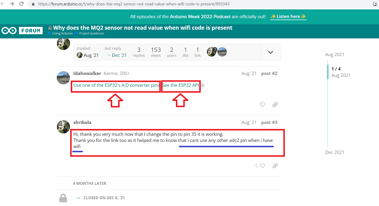
Then someone asked them to change the analog pin to a different analog pin on the board. Also, they suggested to go through espressif's website to read more about limitations of certain ADC pins while wifi is active.
 |
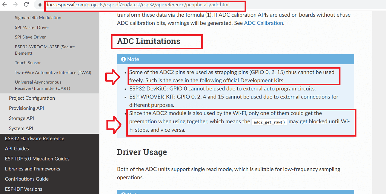
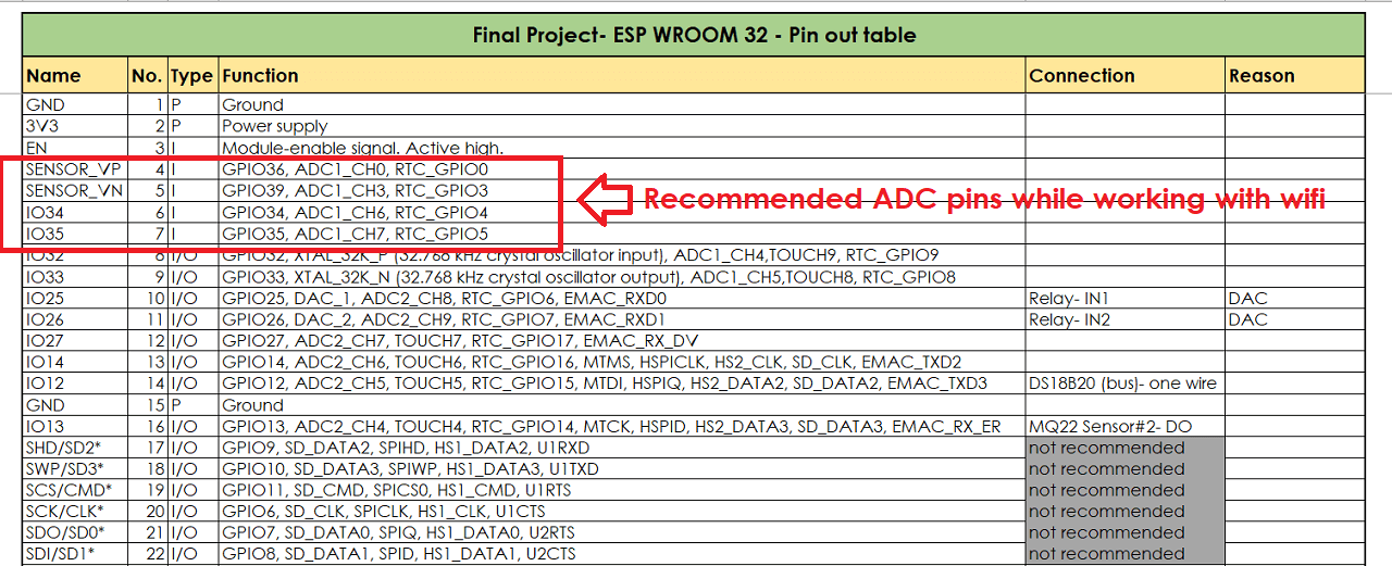
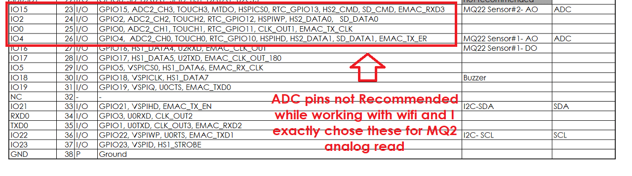
While I too was going through these limitations of ADC pins on ESP32 microcontroller then I found that there are two sets of ADC pins, out of, which they have recommened to use ADC pins- GPIO 34, 35, 36 and 39 and they have NOT recommended to use ADC pins- GPIO 0, 2,4 and 15 while using wifi.
Since, I have made connections only to the ADC pins GPIO 4 and 15 for MQ2 sensor's analog read, I am not able to use both ADC pin and wifi together. Either of them will work. With wifi code, these ADC pins will not work. Without, wifi, they had worked for sure in my case. However, I have not made connections to the recommended set of ADC pins GPIO 34, 35, 36 and 39 while designing my board, I can not use these pinouts any more for the purpose of MQ2 gas sensor's analog read.
 |
 |
 |
Then, I spoke to my Fab lab instructor, Suhas sir and discussed any other possibilities to use the gas sensor with digital pinout. However, since they give only 0 or 1 readings, it is not recommended to use the digital pins for gas sensors. So, we decided to park the use of MQ2 gas sensor for my project for now and concentrate on effectively using the temperature and humidity sensors and their readings to control the exhuast fans in my project and use MQ2 sensor later.
Designed a new board: Integrated MQ2 gas sensor with other peripherals and wifi
For more details on this, pls go to my 'Networking and Communications' assignment.
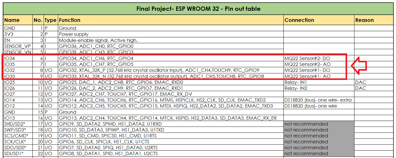
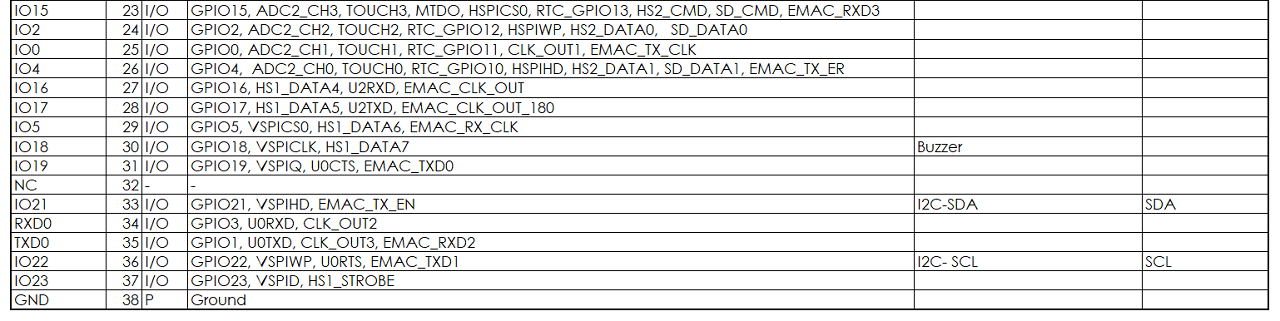
Since, I was having problems with getting gas sensor's analog values along with wifi, I could not integrate the MQ2 sensor in my system. So, I decided to design a new board with different analog and digital pins assigned to the MQ2 sensor so as to make it work with wifi as per the images shown below.
 |
 |
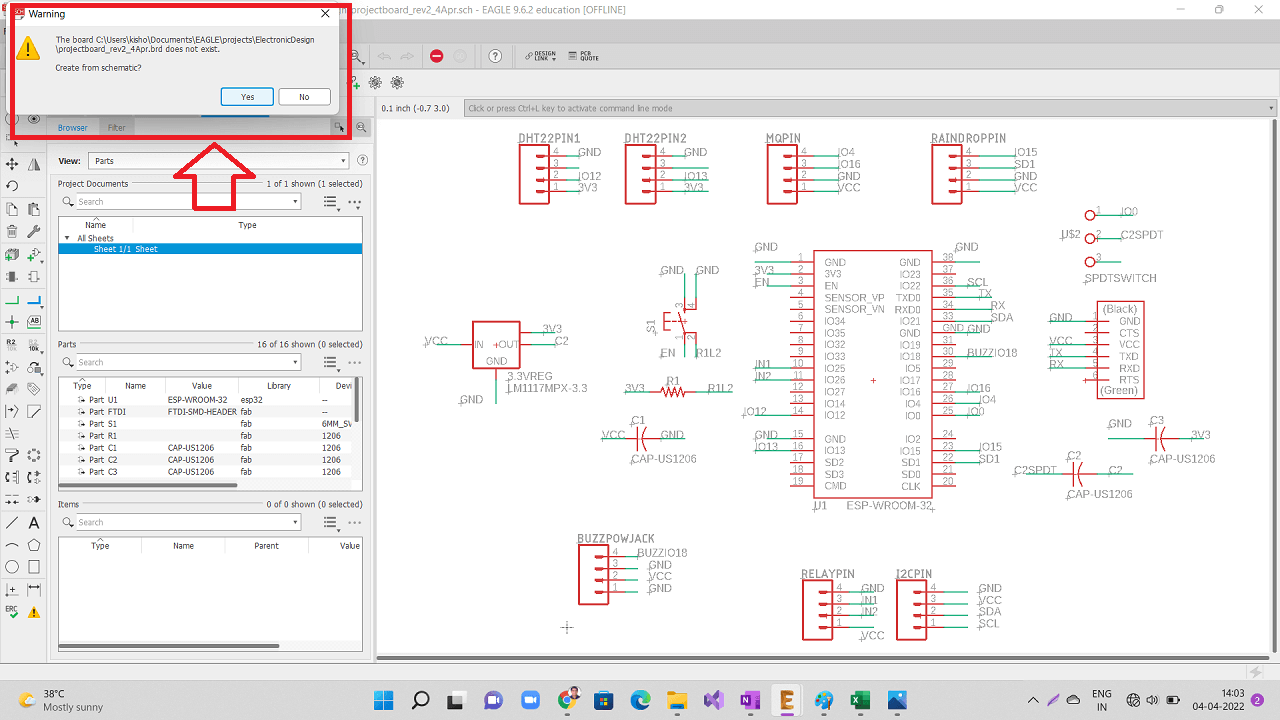
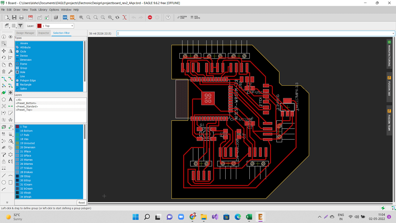
I then redesigned the schematic and board file in eagle as shown below.
 |
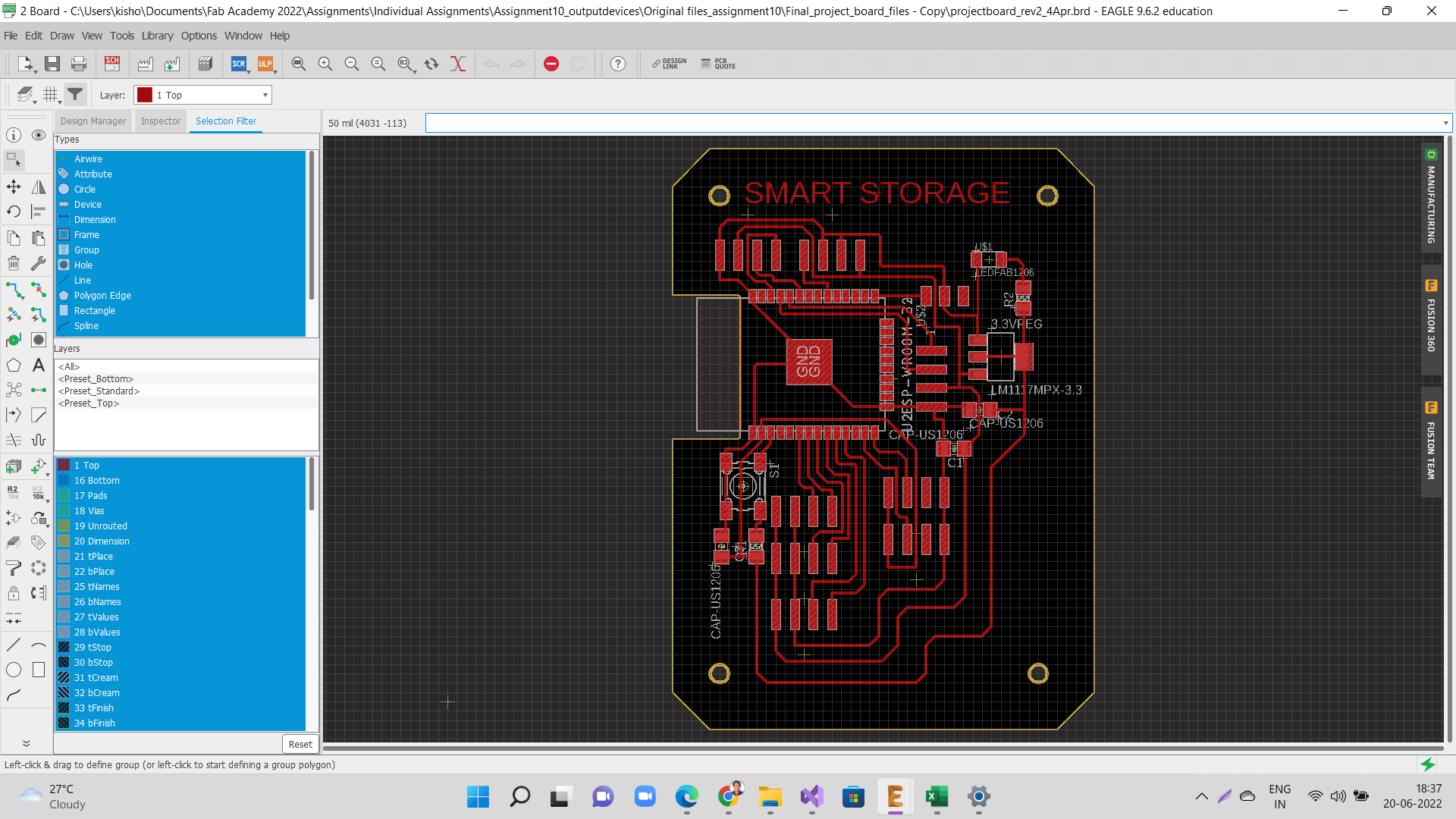 |
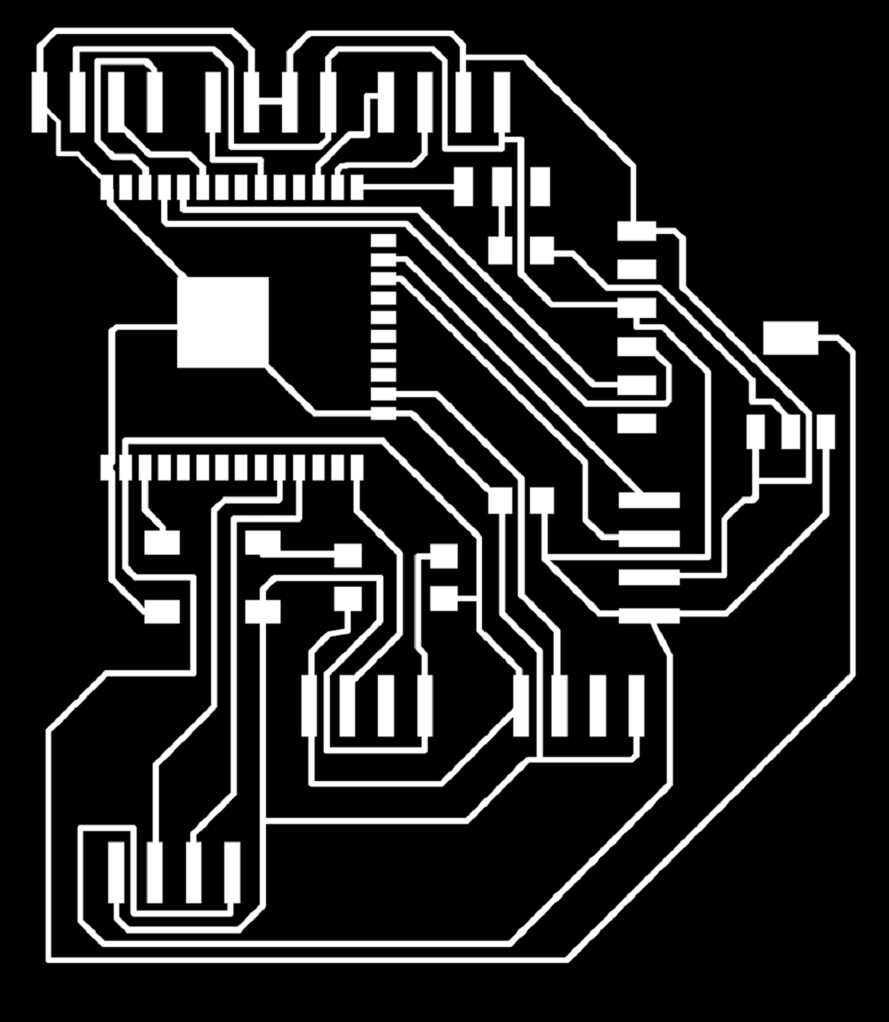
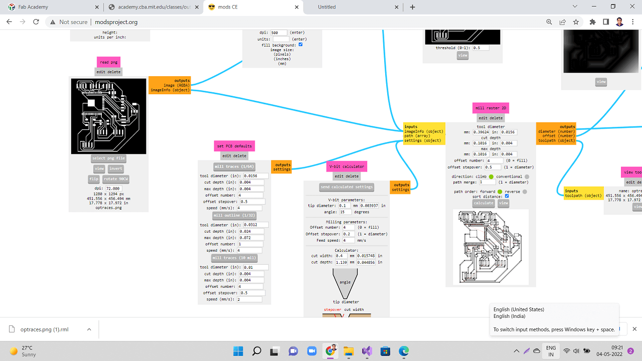
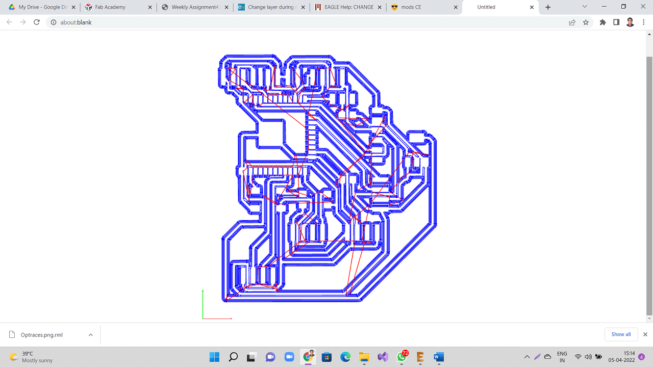
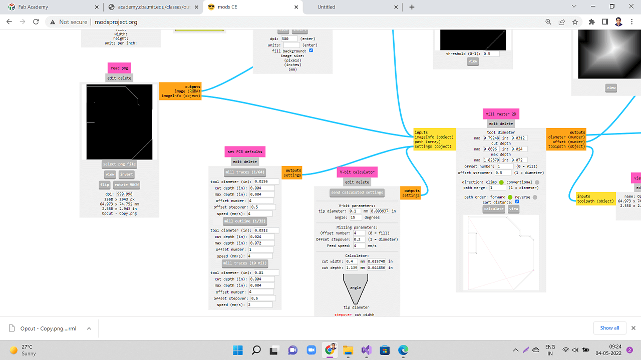
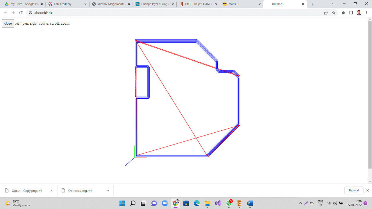
Following are traces and outer cut png files that I used for generating the toolpath.
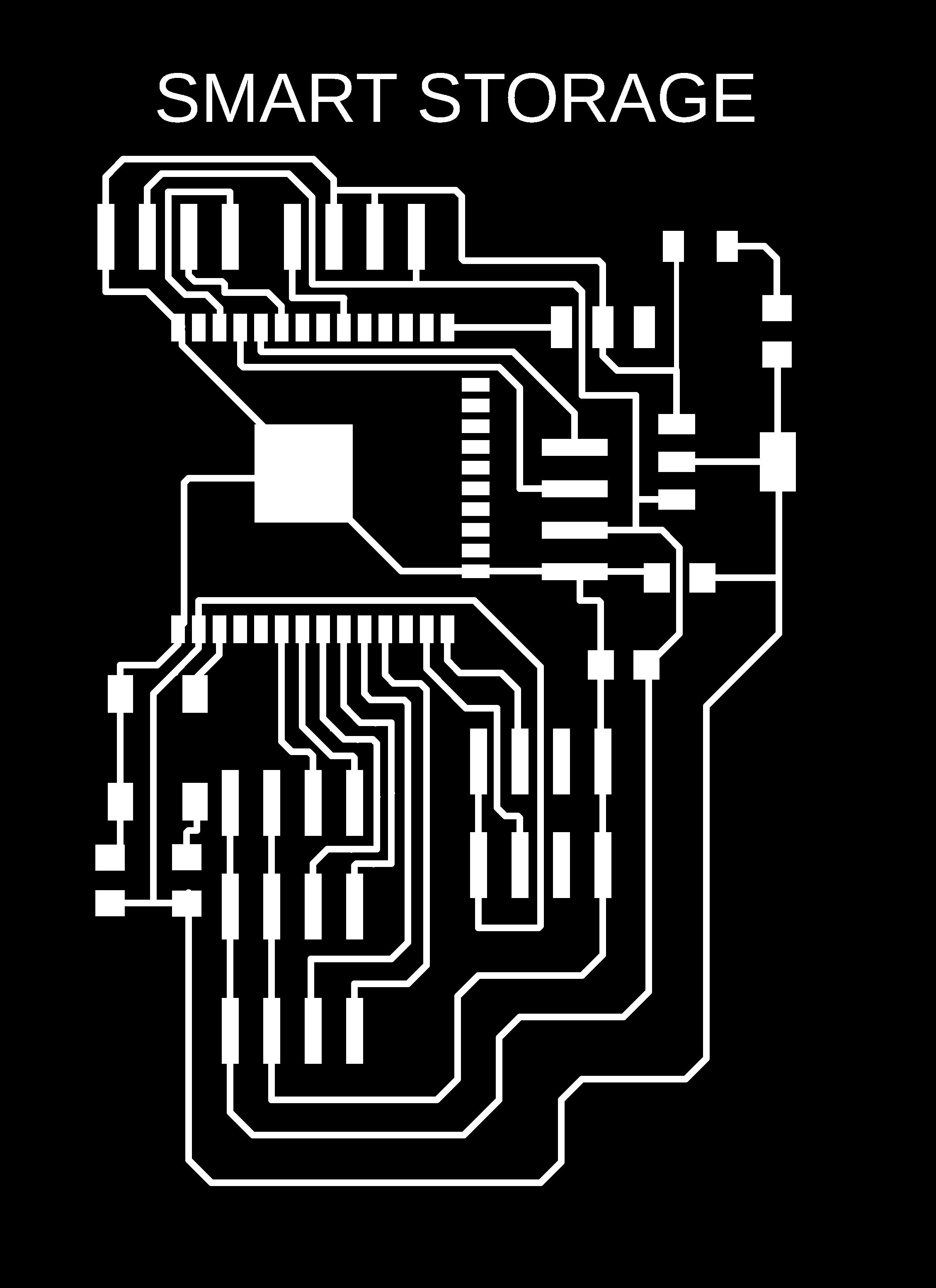 |
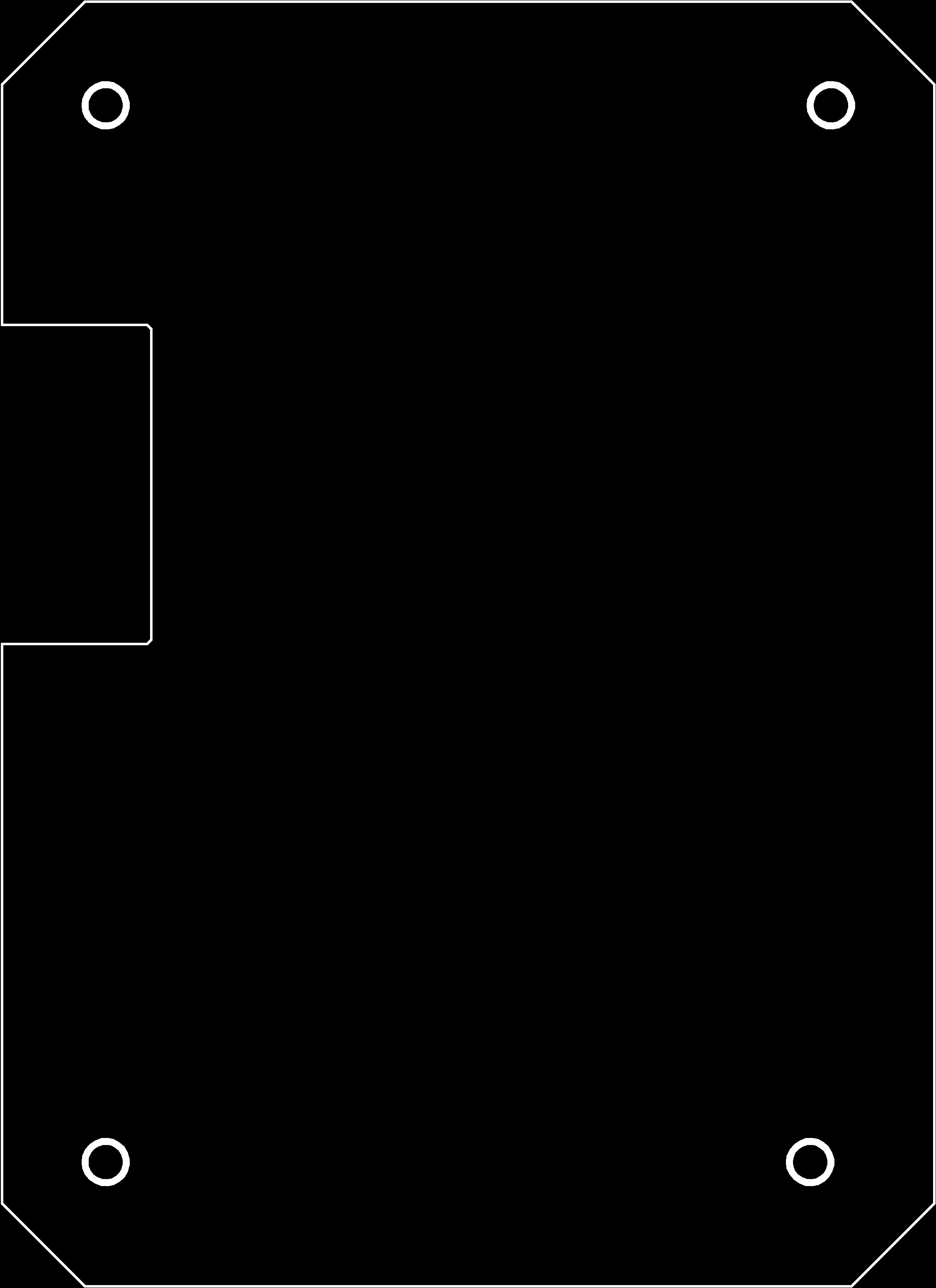 |
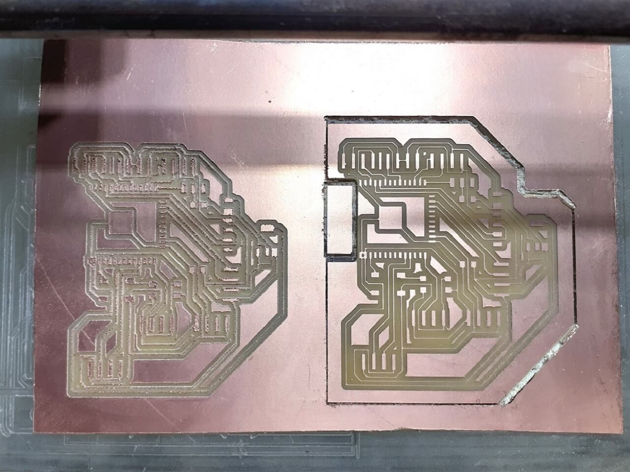
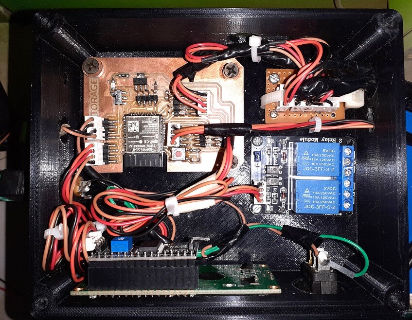
I assembled the new board as shown below.
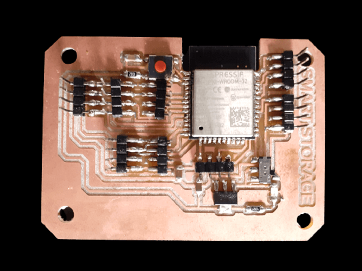 |
Click here to go back to the top
Application development through MIT app inventor and Google Firebase:
For more details on this, pls go to my 'Interface and Application Programming' assignment.
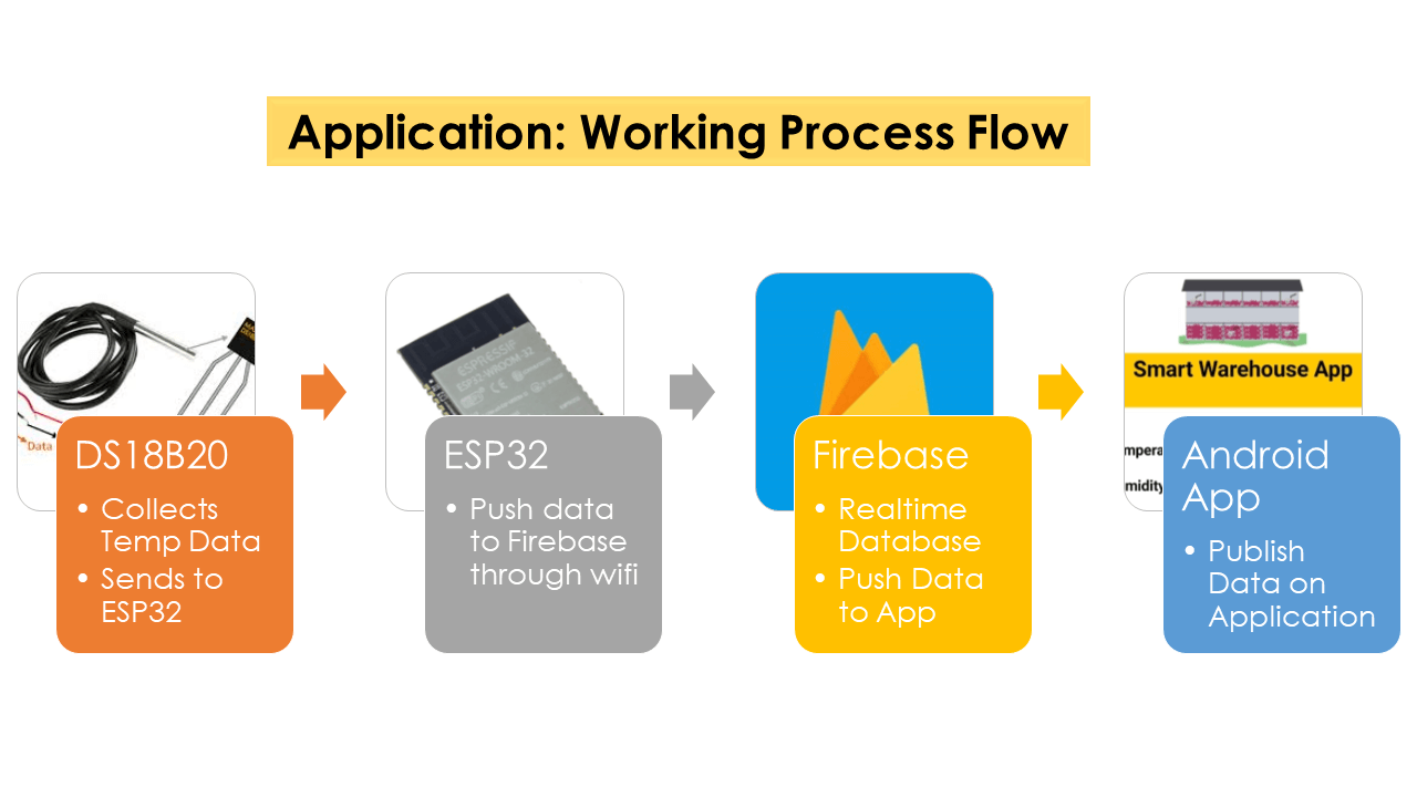
For my final project, I have developed android app using MIT app inventor. To do this, I am sending sensor data to the Android app through Google Firebase using Arduino IDE. The application displays sensor readings on our smartphone. The sensor readings could be accessed anywhere and anytime conveniently. I have used Arduino IDE to program my project board (ESP32- Wroom), which is be connected to multiple DS18B20 sensors. The sensor readings are sent to the Google Firebase database, which will push the sensor readings in real-time through my app which that I built using MIT App Inventor.
Following is a work process flow of the application:
 |
Setting up Arduino IDE for application development:
Installing Google Firebase ESP32 Library:
To be able to use Google Firebase with my ESP32 board, I have installed Firebase library in my Arduino IDE. To download the library, click here. Click on 'Code' and then 'Download Zip'.
Inside Arduino IDE, go to Sketch > Include Library > Add .zip Library to add the library to the program.
.png) |
4. Arduino Sketch to Send Sensor Data to Google Firebase:
Click here to see/copy my project program after adding app portion to it or download sketch from the cloud screen below.
Code explaination:
I first included the necessary libraries at the beginning of the code, e.g. wire library for I2C device communication (LCD in my case), the OneWire and DallasTemperature for the DS18B20 temperature sensor, LiquidCrystal_I2C for I2C serial interface adapter used with 16x2 LCD screen, ThingSpeak library for communicating data to ThingSpeak cloud and wifi library for using wifi. I also have added Firebase library that I downloaded in the step above.
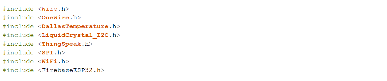 |
Then, I declared a LiquidCrystal 12C object with 12C address, the number of columns, the number of rows (16 columns and 2 rows in my case)
|
I defined SSID and password for my wifi network along with Channel ID and Secret Write API key for my ThingSpeak IoT channel. I have also added Firebase host and Firebase authorization key that I had saved in the step above for setting-up Google Firebase.
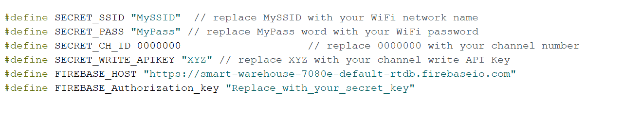 |
After that, I created two char variable called char ssid[] and char pass[] to save the SSID and password.
|
Through WiFiClient, I created a client that can connect to a specified internet IP address and port as defined in client. int keyIndex = 0; is network key Index number (needed only for WEP).
|
I also created one unsigned long variables (extended size variables) for storing my Thingspeak Channel ID along with const char* to declare Write API key for my channel.
|
I defined upper threshold temperature for my project above, which the exhaust fans will be switched ON. I defined GPIO 12 for onewire bus for DS18B20 sensor and GPIO 26 for Relay pin.
|
After defining the DS18B20 sensor pin I created objects OneWire and DallaTemperature to make it work.
|
I then defined the FirebaseData object as 'firebaseData'. This will be used later on in the code to access the sensor readings.
 |
In the setup(), set the RelayPin as an output. Then, added lcd.begin() to initialize the interface to the LCD screen, DS18B20.begin() function to search for connected sensors on the bus and sets bit resolution (12 bits) for each one of them. Also added lcd.backlight() function to start the LCD backlight. WiFi.mode(WIFI_STA) sets up station mode for ESP32 to connect to an access poin. Lastly added ThingSpeak.begin(client) to initialize ThingSpeak.
Additionally for Firebase, I will connect my board with Google Firebase by using the Firebase.begin() function. It takes in two parameters. The first is the Firebase host and the second is the authorization key. I have defined both of them earlier on in the program code. Through correct credentials, a successful connection will be made.
 |
In the loop(), wifi connection is made. Connecting to a Wi-Fi network can take a while, so we usually add a while loop that keeps checking if the connection was already established by using WiFi.status(). When the connection is successfully established, it returns WL_CONNECTED. To get the status of the Wi-Fi connection, I used WiFi.status(). This returns WL_CONNECTED value, when it is connected to a WiFi network. I then used WiFi.begin() to connect to a network.
|
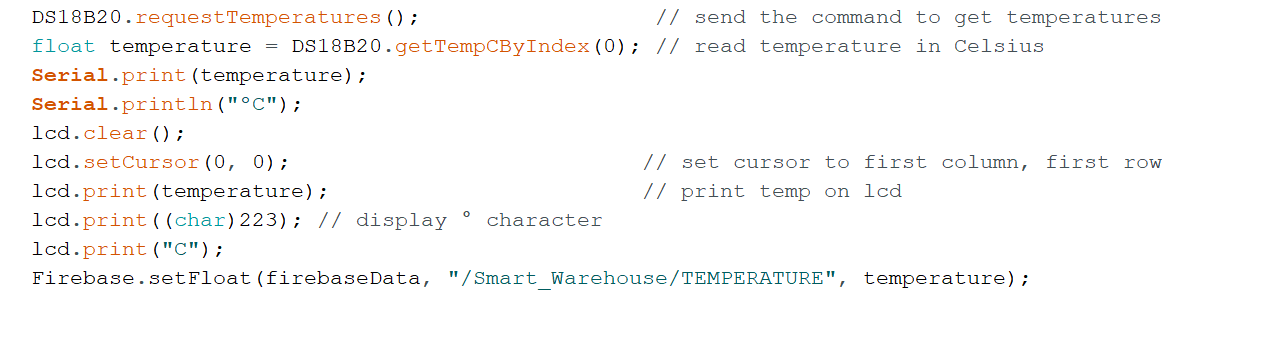
DS18B20.requestTemperatures() function is used to send command for all sensors on the bus to perform a temperature conversion. Defined 'temperature' as a float. DS18B20.getTempCByIndex(0) function reads and returns temperature reading from the sensor. deviceIndex is nothing but the location of the sensor on the bus. If you are using only one DS18B20 on the bus, set it to 0. The additional ones will be 1, 2, 3 and so on after the first one as 0.
Then, lcd.setCursor(0, 0) Move cursor to the desired position (column_index, row_index), (0, 0) in this case. lcd.print(temperature) prints Temperature value read by the sensor.
Through Firebase.setFloat() my app will be updated with the current temperature readings. This function will take in three parameters. The first is the FirebaseData object which I have already created. The second is the 'project name/the name of the tag', which I will set in my MIT app inventor block. I have given it a name 'Smart_Warehouse', which I will explain in detail in the steps below. Lastly, I have specified the variable 'TEMPERATURE' in, which I am saving my updated sensor variables i.e., 'temperature'. This variable 'TEMPERATURE' will appear in MIT app design inside blocks workspace.
 |
The if statement in the code reads the temperature values and takes appropriate action with regard to the Relay pin. The logic works like this, if the temperature goes above the upper threshold value defined earlier in the code, the microcontroller turn relay's GPIO pin HIGH and LOW if it is below the upper threshold value.
|
Lastly, I defined an int x to push the temperature values on to the field#1 I have created on my ThingSpeak channel. The channel ID and myWriteAPIKey are already declared in the code above.
|
I updated my code with gas sensor integrated in to the system. You can copy/download the code from the cloud.
For more details on this, pls go to my 'Networking and Communications' assignment.
Wow, my app started displaying the temperature values as shown in the left image below. The left-most image is taken after I added temperature and humidity values for second sensor. The right-most image is taken after I added MQ2 gas sensor analog values.
.jpg) |
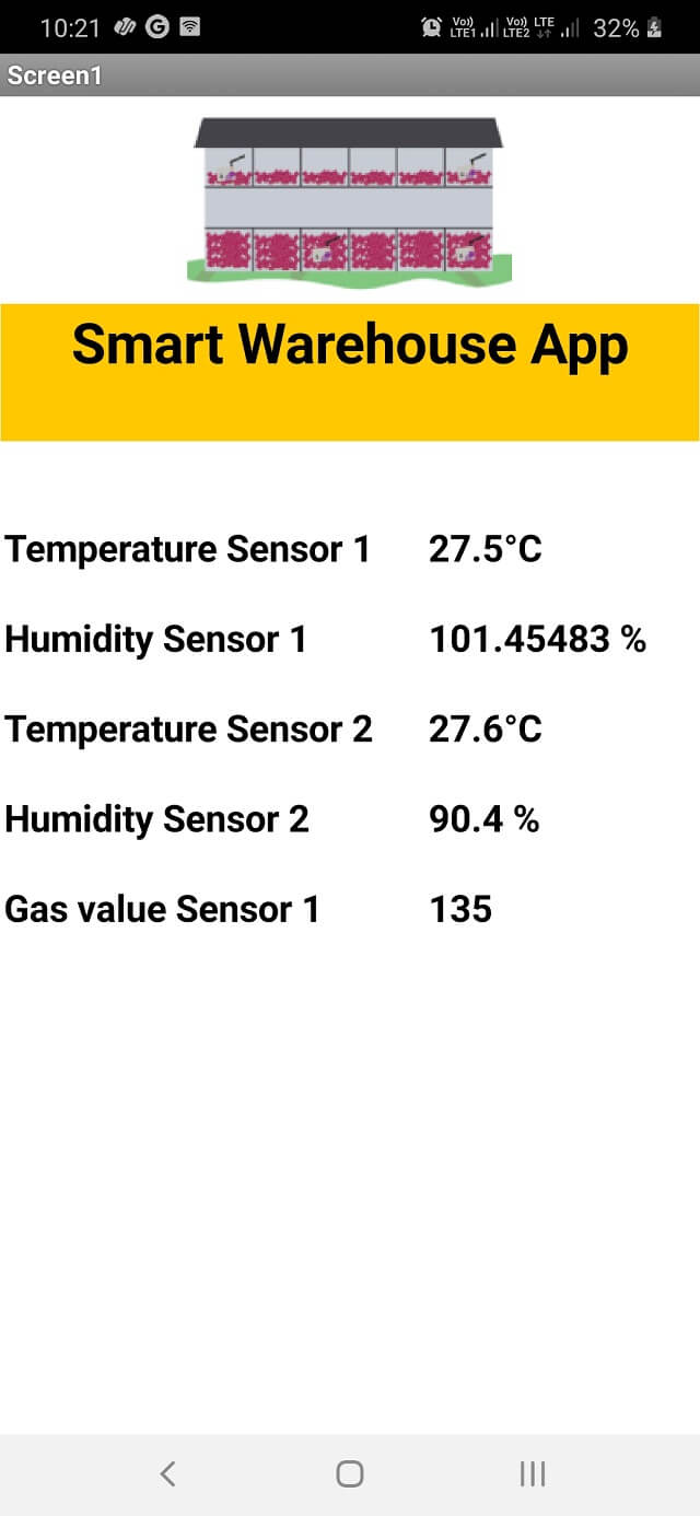 |
This is how my app started working:
Following images are showing my final project set-up with DS18B20 temperature sensor connected to my project board. Along with it, I have connected LCD, relay. The temperature values are seen displayed at a time on LCD, my app and ThingSpeak IoT channel I had established in my last assignment.
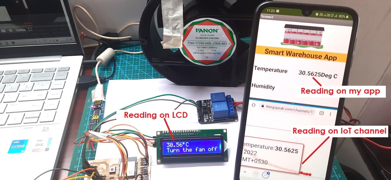 |
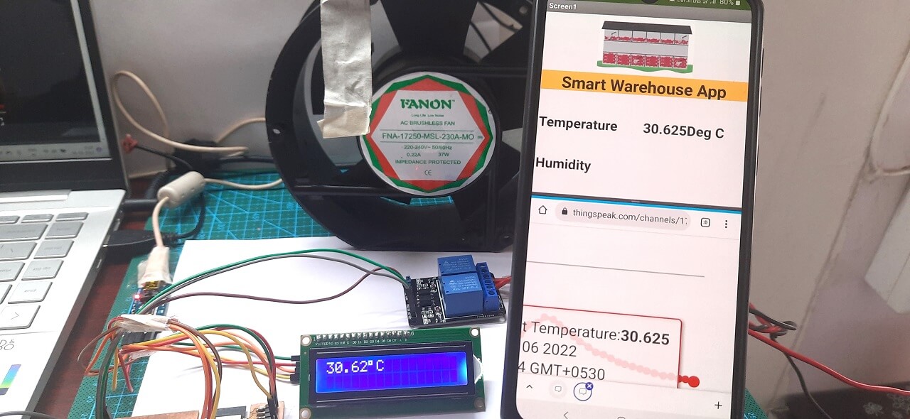 |
Adding videos for application development
1. Collecting DS18B20 Temperature sensor data on application.
2. Collecting Temperature sensor and MQ2 gas data on application.
Click here to go back to the top
Packaging and System Integration
For more details on 3D Printing for final project, pls go to my '3D Scanning and Printing' assignment.
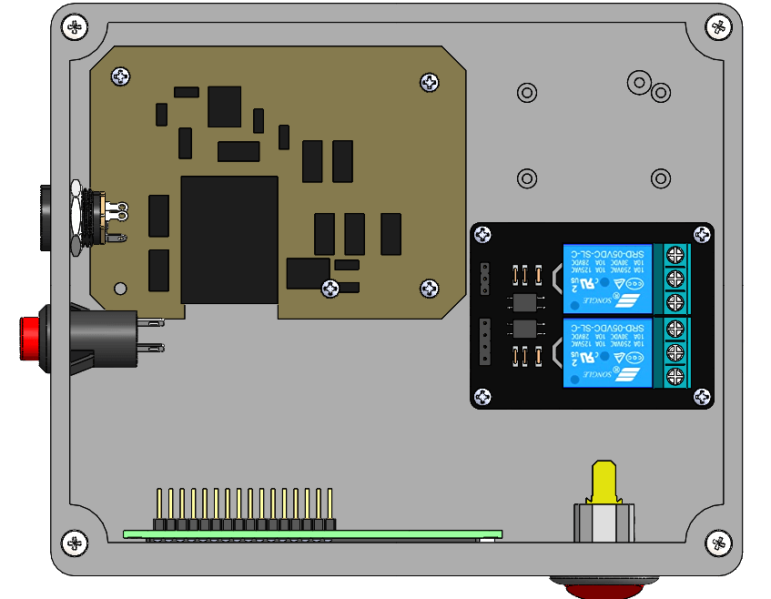
I designed the enclosure in solidworks for 3D printing it. I assembled 3D CAD models of my board, LCD, 2 channel relay, buttons, power jack socket, etc. to ensure I have optimum space for assemblying the actual components inside the box.
Following is a picture of the CAD model that I designed for 3D printing the enclosure for electronics of the system.
|
|
I did slicing in fraktory software for generating toolpath for 3D printing as shown below.
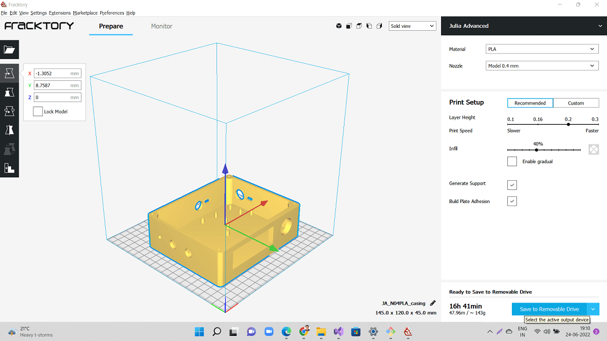 |
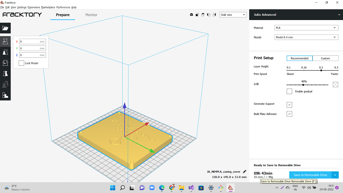 |
3D Printing of Enclosure
Short video on 3D Printing of casing for final project.
Following are the pictures of enclosure designed and actual enclosure I 3D printed and assembled. I arranged these two pictures side-by-side to compare designed vs actual assembly.
|
|
Following are the pictures of system integration- design vs actual.
 |
 |
Final testing of system before installation on site
Click here to go back to the top
Fabrication and assembly
Following are the pictures of storage system designed and actual storage system I fabricated. I arranged these two pictures side-by-side to compare designed vs actual set-up.
|
|
Following are some of the glimpes of fabrication process.
Click here to go back to the top
Installation and Results
Final installation and Testing
Working of the system
Results
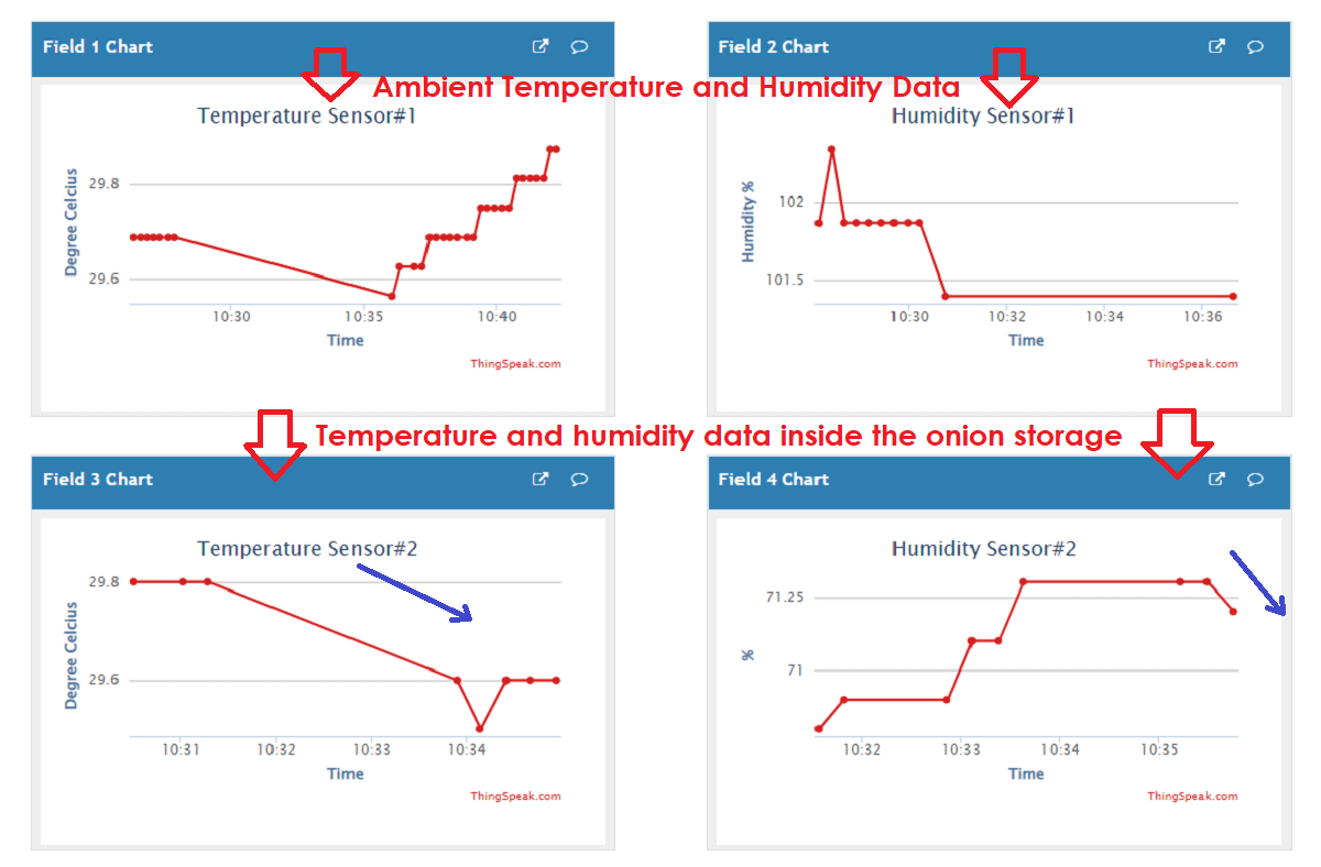
The system works like this- As the ambient temperature and humidity increase above 30 Degree Celcius and 70% respectively, the ventilator fan switches ON to cool the onions stored. You can see from the below images from the temperature and humidity sensor data collected through Thingspeak that, as the ambient temperature and humidity goes above threshold values, the temperature and humidity values start falling down or remain stable because the system has switched ON the ventilator fan.
 |
Click here to go back to the top
Bill of Materials and Costing
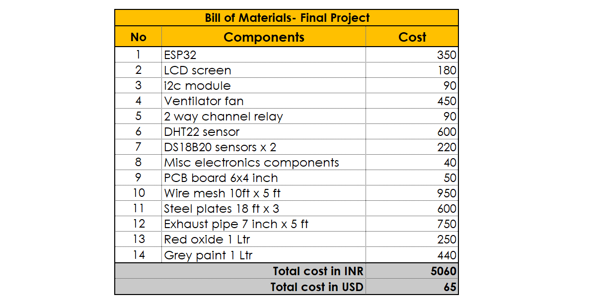 |
Click here to go back to the top
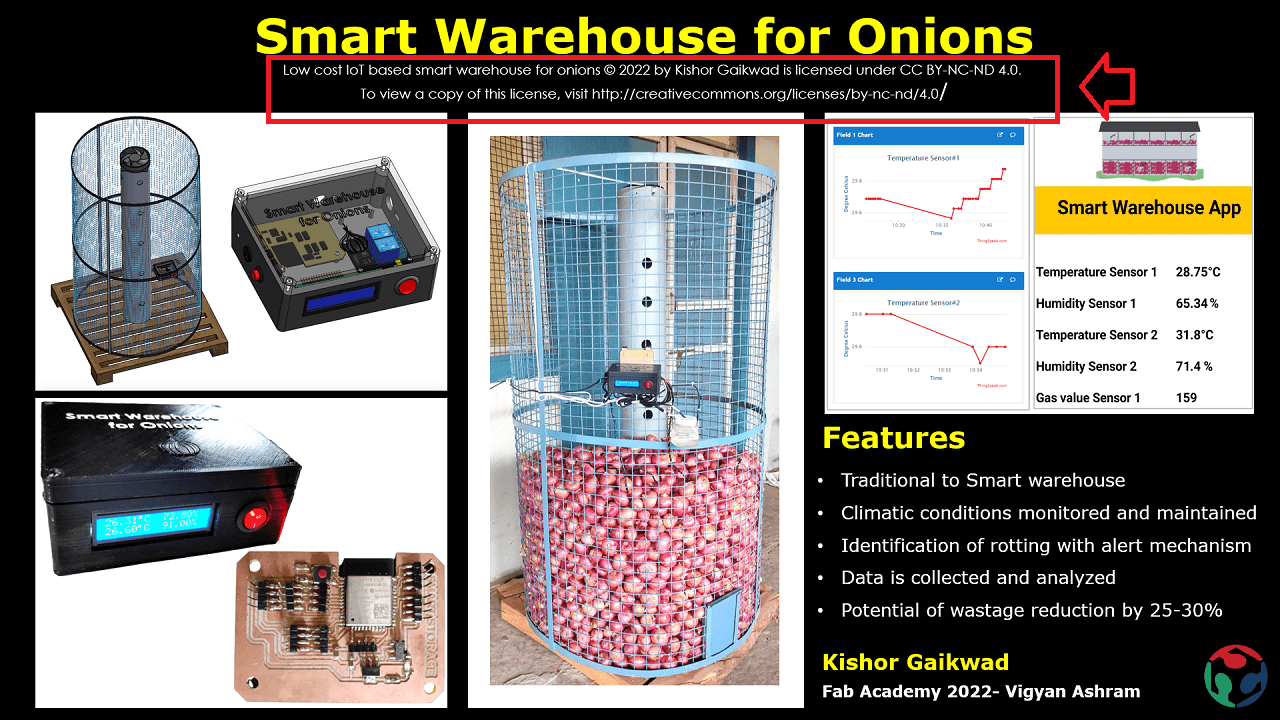
Final Presentation Slide
 |
Final Presentation Video
Click here to go back to the top
Licence chosen
For more details on License application, pls go to my 'Invention, Intellectual Property and Income' assignment.
Low cost IoT based smart warehouse for onions 2022 by Kishor Gaikwad is licensed under CC BY-NC-ND 4.0. To view a copy of this license, visit http://creativecommons.org/licenses/by-nc-nd/4.0/
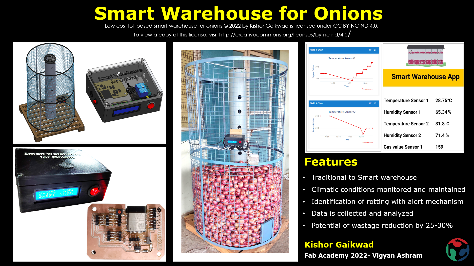
I have added the license details at the footer of my final project page and I have also added the license details as a plain text below the project name on final project presentation slide as shown below.
 |
 |
Download Original Files
Click here to download final project CAD original files- Archive#1.
Click here to download final project CAD original files- Archive#2.
Click here to download Eagle Board Files for final project.
Acknowledgement
I would like to sincerely thank Prof. Neil and his team, Vigyan Ashram Director- Mr. Yogesh Kulkarni sir, Deputy Director- Mr. Ranajeet Shanbhag sir, my fab academy instructors Mr. Suhas Labade, Ms. Arundhati Jadhav, my colleagues- Mr. Kiran Wakchaure, Ashish Shende, Jaydeep Patel, Vrushabh Zunjurkar, Fenil Chandrana and Devesh Nair. I also want to appreciate Vigyan Ashram Fab lab fellows, Rahul Kanojia, Rutika Ghodekar, interns- Purushottam, Omkar and Prasad, DIC members, Mr. Purnesh, Workshop staff, Mr. Laxman Jadhav, Mr. Kailas Jadhav for helping me in my fab academy assignments and final project.