
Assignment#11: Mechanical Design, Machine Design
This assignment is about documenting what I learned in Mechanical Design and Machine Design week that includes what all we did as a group and I did as an individual in making a machine. The tasks were divided as per the processes and yet work was completed through a collaborative and concurrent approach. This documentation includes our concept, brainstorming and processes (work break-down) we followed in designing and constructing our machine in brief. My contribution in to this project is documented in detail.
Name of our Machine is 'Mudrak'. It is a Hindi word, which in English means a 'Printer'.
My Contribution towards this Assignment:
- I along with Fenil took the responsibility of mechanical design that includes 3D CAD modelling of the machine. I modelled one frame and also completed the entire machine assemblu in solidworks.
- I also took part in other tasks like fabrication (laser cutting, 3D printing, cutting and grinding), electronics (specifically hardware portion).
- I compiled and also edited the group assignment documentation along with creating video for the machine week presentation to fab academy.
Objectives of the Assignment (Group and Individual):
Mechanical Design
- Design a machine that includes mechanism + actuation + automation + application
- Build the mechanical parts and operate it manually
- Document the group project and your individual contribution
Machine Design
- Actuate and automate your machine
- Document the group project and your individual contribution
Go to our machine site to know more about machine and group work.
Our Hero shots and videos:
 |
 |
 |
 |
Click here to go back to the top
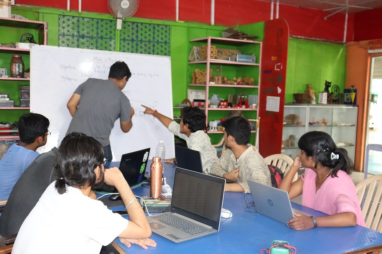
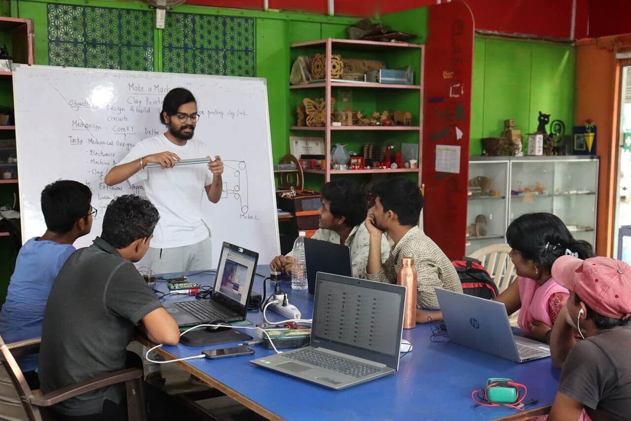
Concept
We had a brainstorming session to decide on the machine, it's applications and what kind of mechanism should the machine have. We had different ideas; however, we thought of making a machine that can print circuits using materials like conductive clay or ink, etc.
 |
 |
The idea behind using a conductive clay or ink is to make a low-cost material, which is easily available. We thought of making the conductive clay using a play dough (made of common flour) that can be safely handled by the children. We went through the following video to know more about the conductive clay. Source and Credit for the literature: TED Talk youtube channel
We also went through Squishy circuits website and other websites for refrence.
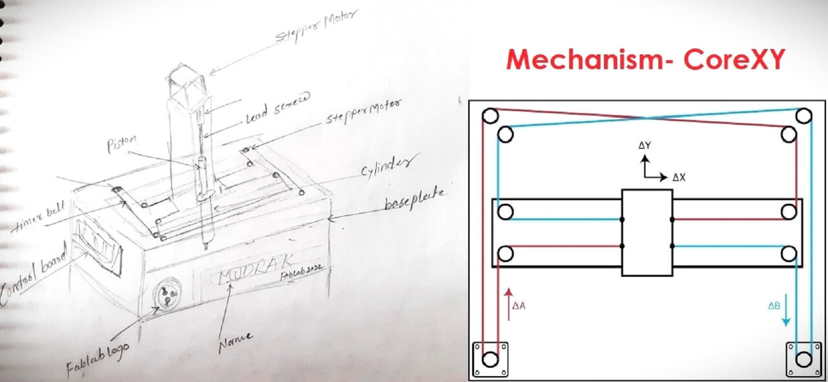
Selection of a Mechanism:
Together as a group, we went through different mechanisms that can be best suited to design and build a printer. We concluded to use CoreXY mechanism in our printer. Click here for Reference and credits.
 |
Click here to go back to the top
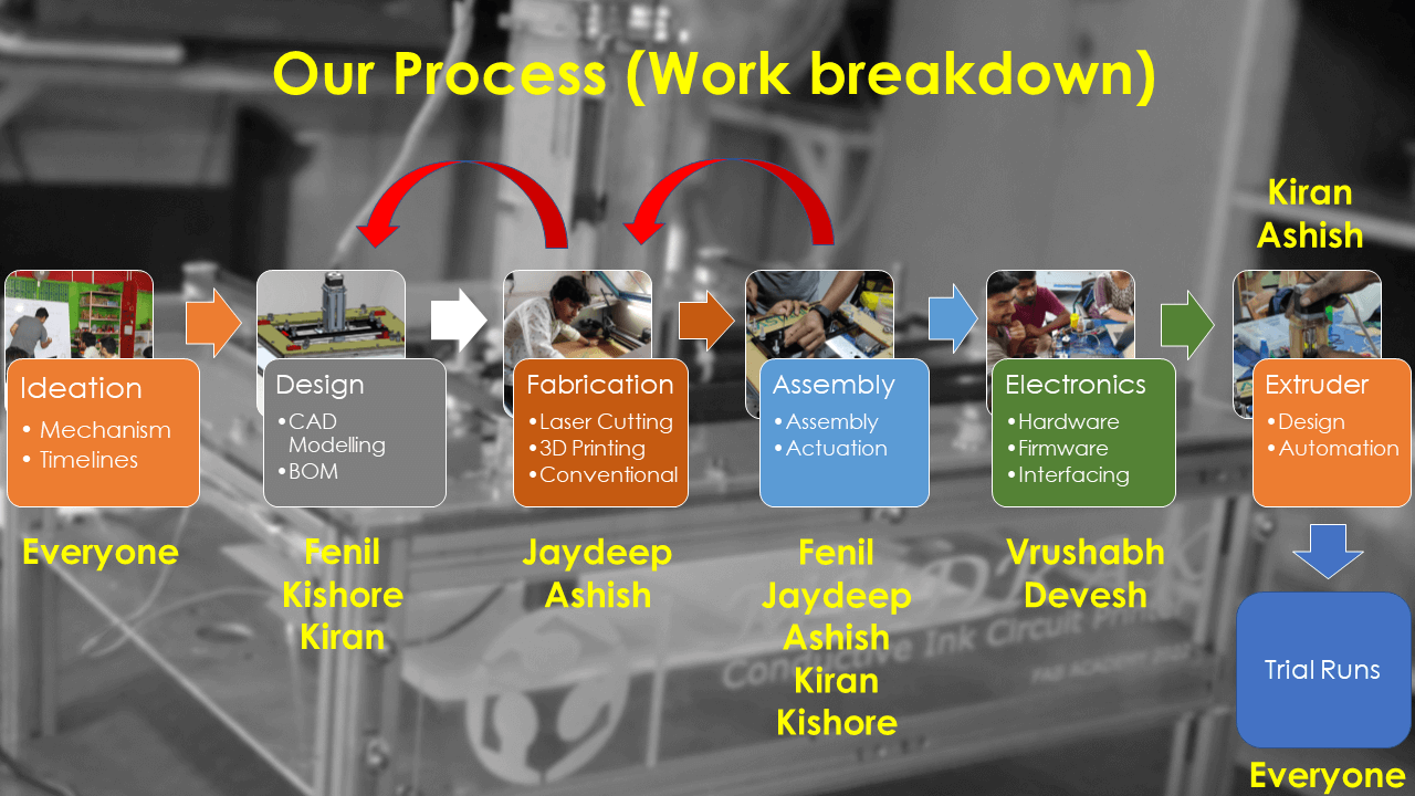
Process Flow
We assigned following tasks amongst ourselves building the machine.
1. Fenil and Kishore took the responsibility to design the CoreXY mechanism and gantry of the machine.
2. Kiran had the responsibility to design the extruder and prepare the conductive ink.
3. Jaydeep took the responsibility of all the fabrication like laser cutting, 3D printing, conventional cutting and grinding.
4. Devesh and Vrushabh had the responsibility of electronics part, which included electronics hardware, firmware and interfacing.
5. Ashish was majorly contributing in to assembly process (entire machine including the extruder assembly) and preparing the conductive ink.
It was decided that after all the sub-assemblies and ink become ready, everyone will participate in the assembling and testing of the machine through test runs followed by the testing of the application (working on the circuit printed using the conductive ink).
 |
Click here to go back to the top
Mechanical Design
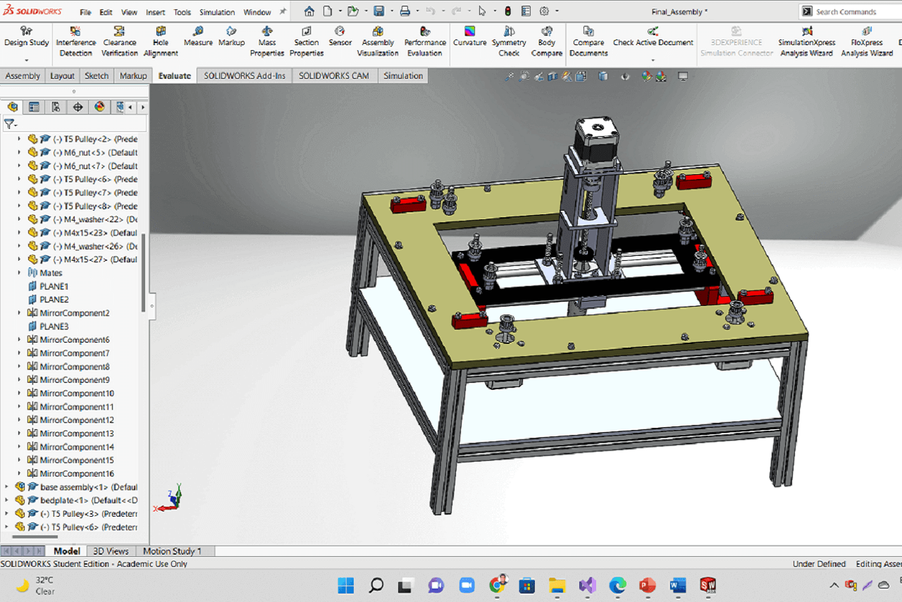
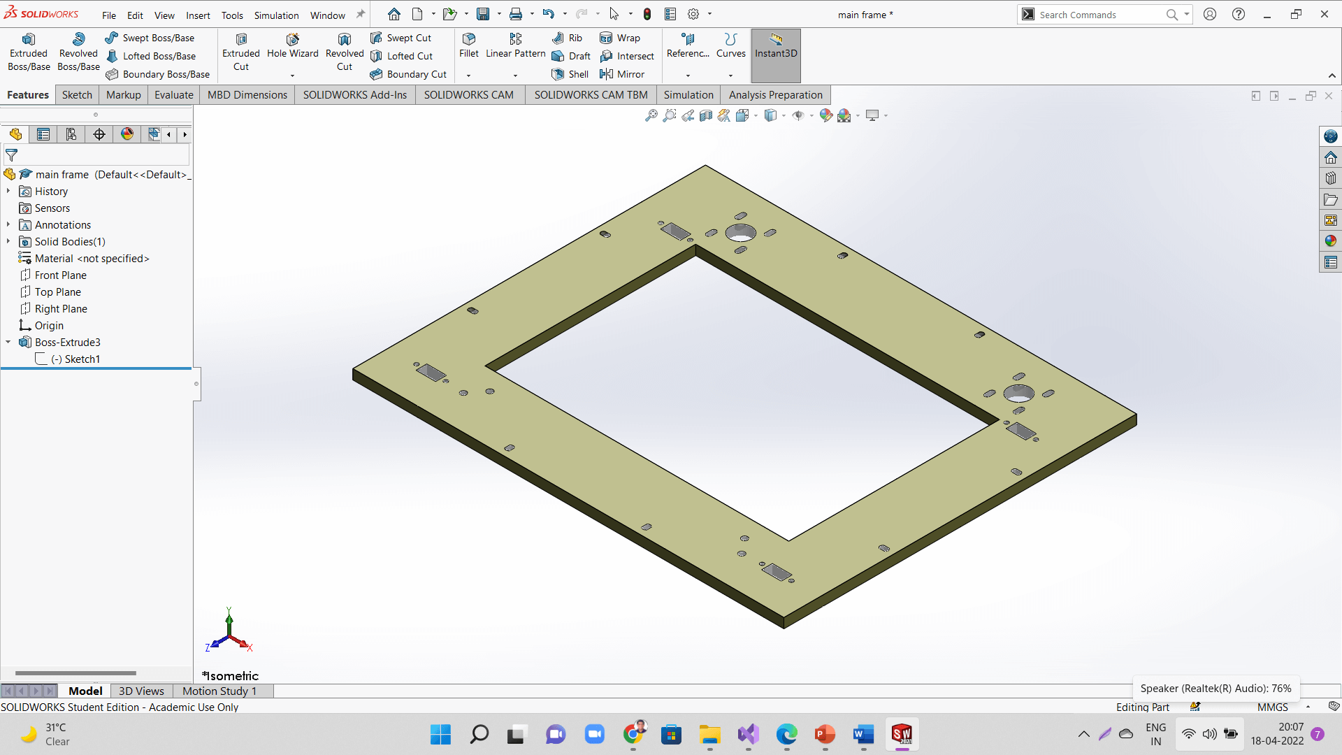
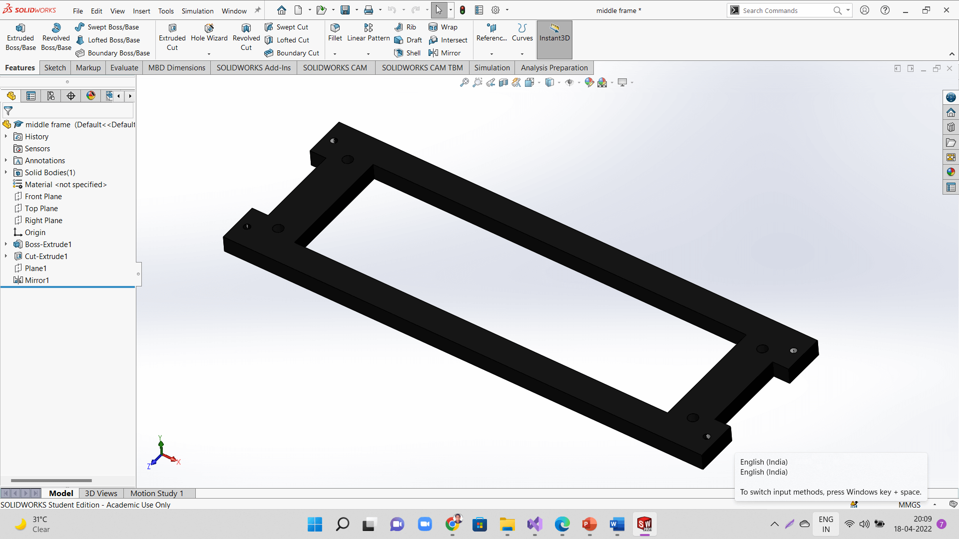
We designed the entire mechanism and other parts in solidworks. Below is our 3D model of the machine. I contributed in to taking the initial measurements of the material available and start building the main frame. Fenil worked on designing the middle frame parts and the sub including the base frame assembly. Kiran sir worked on the extruder assembly design. Later, I made the entire assembly in solidworks by adding the other parts like stepper motors, timing belts and pullies, linear bearings, 3D printed L bracket and T-slot holder and hardware. I also created the animation and rendering of the model. Finally, I converted the final assembly file in to step file and uploaded on the repo.
|
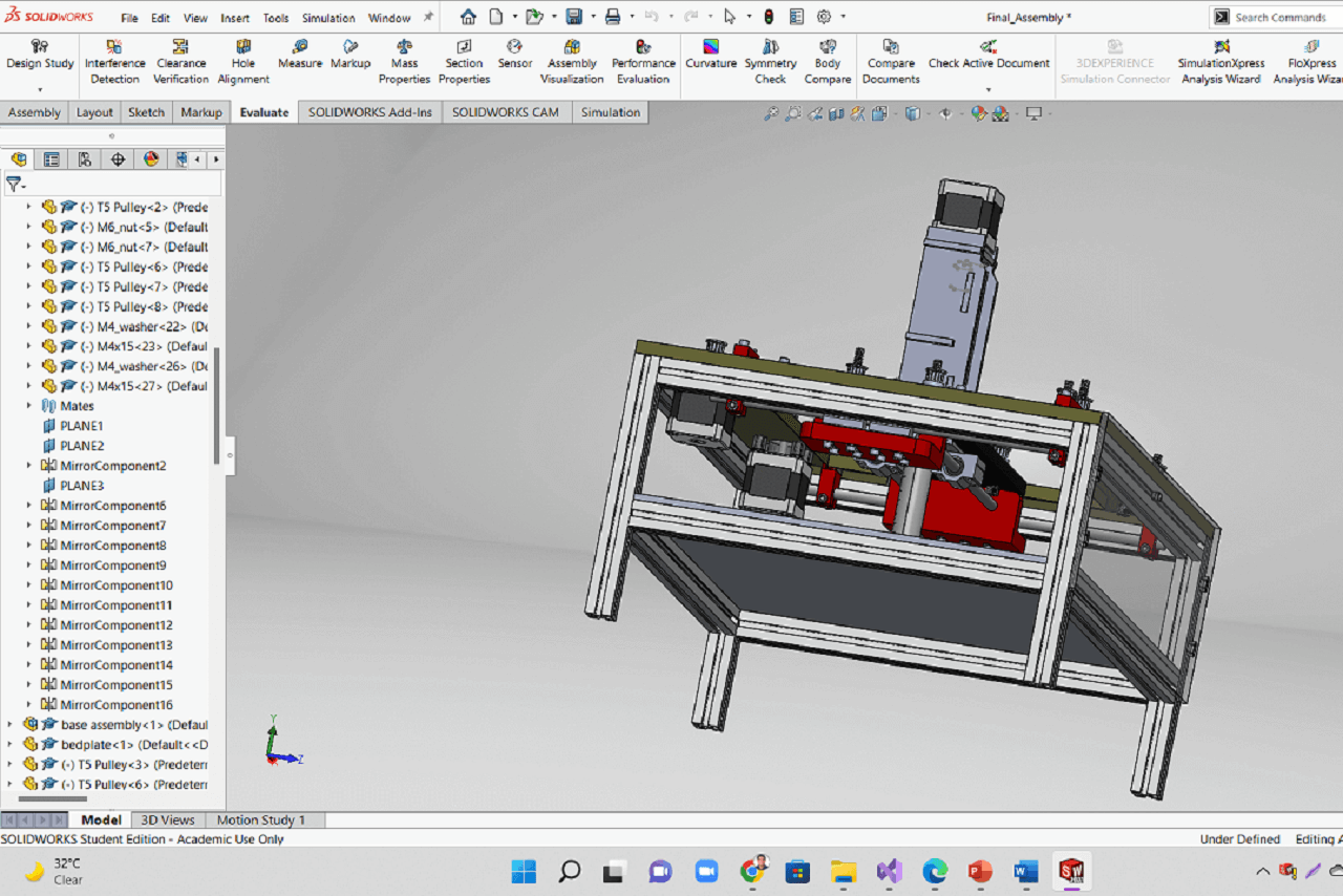 |
Below is an animation we captured from the assembly file.
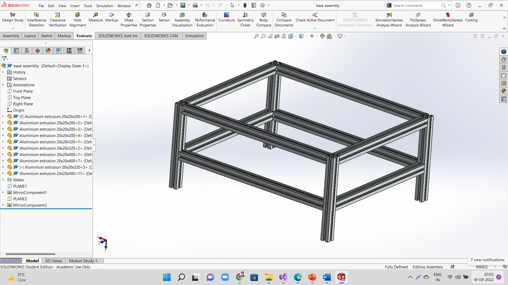
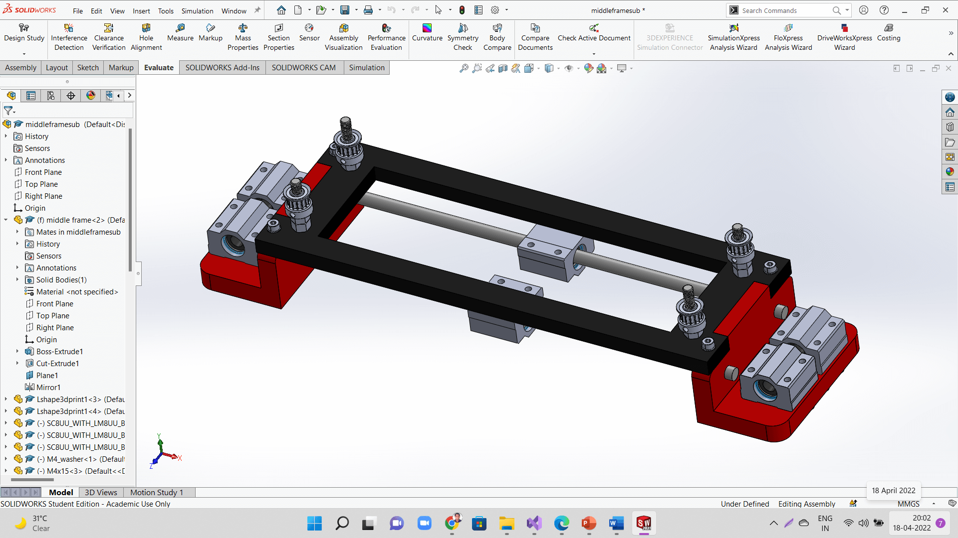
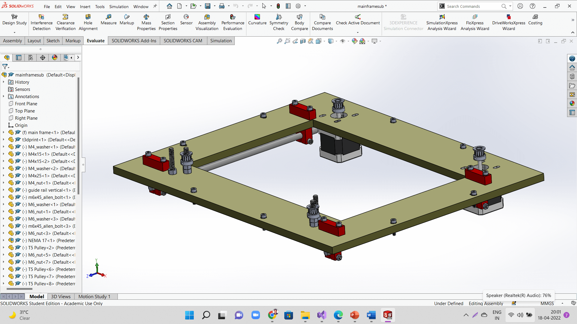
Following are the sub-assemblies of the machine.
 |
 |
 |
Kiran sir designed the extruder assembly.
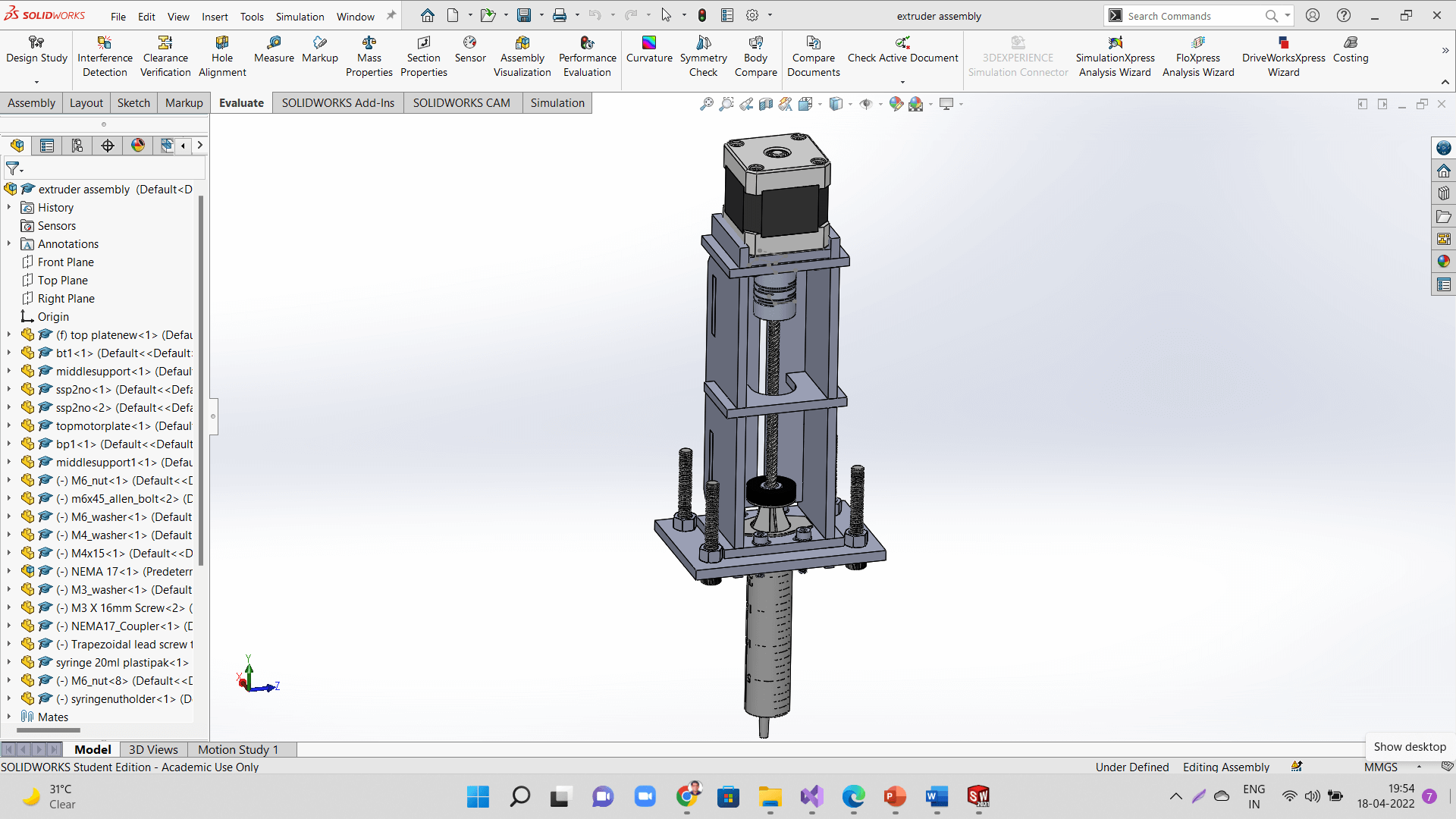 |
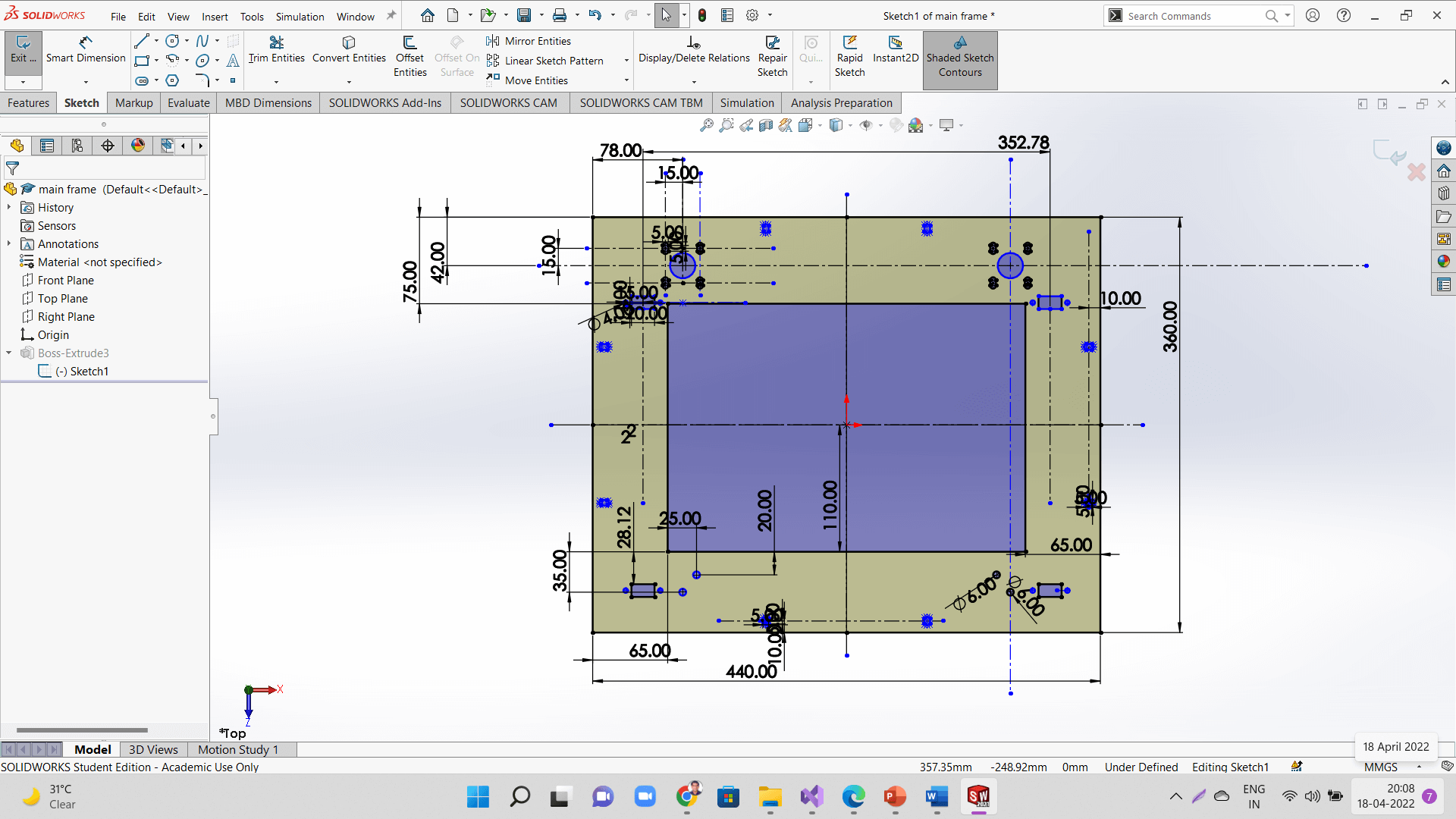
Following are the 3d models of sketches of some of the major parts.
 |
 |
 |
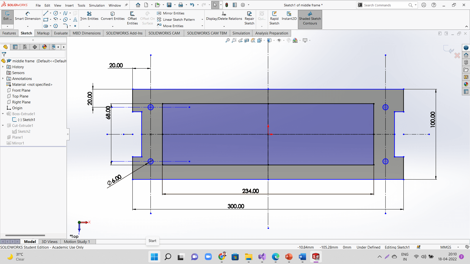 |
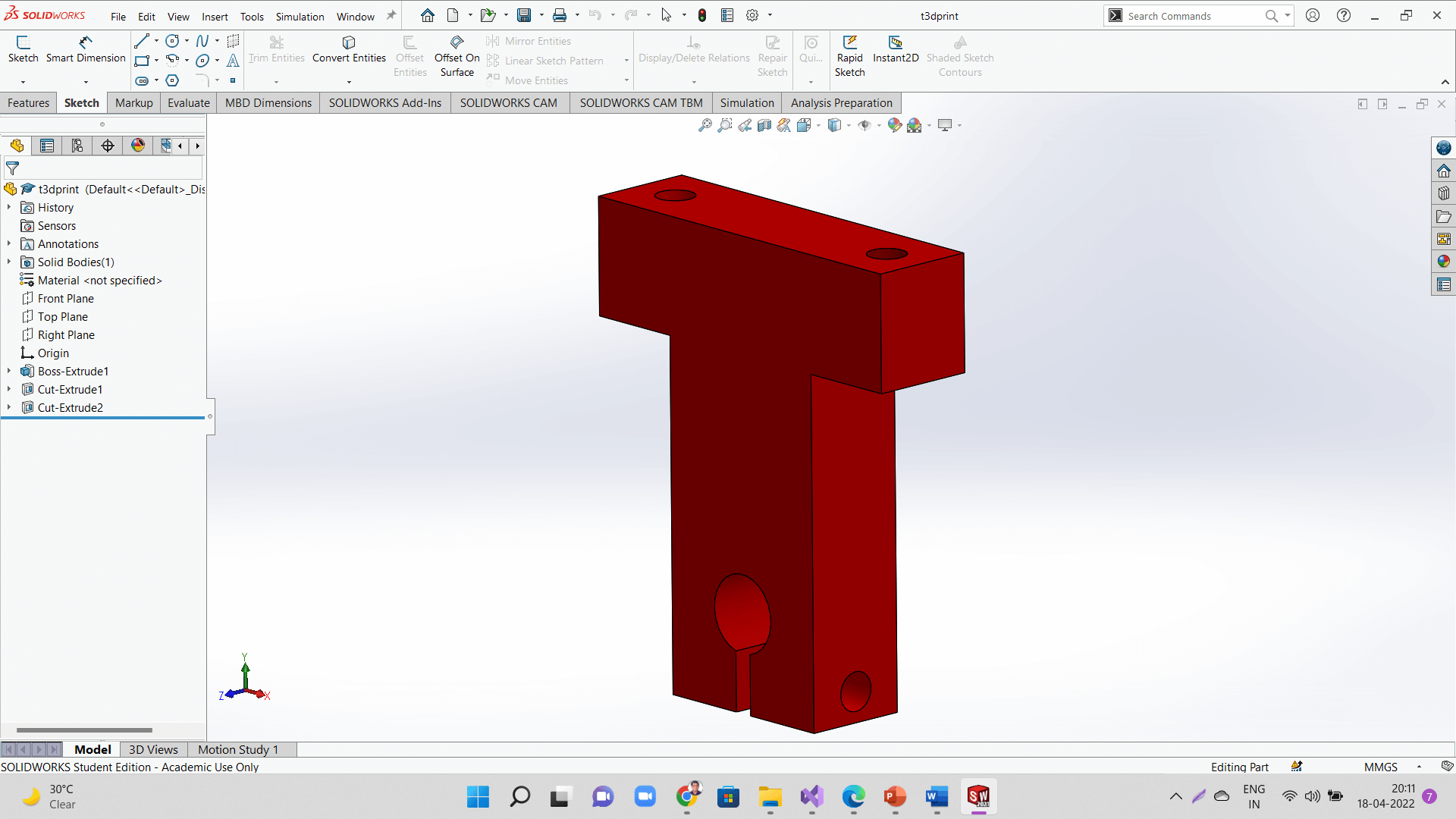 |
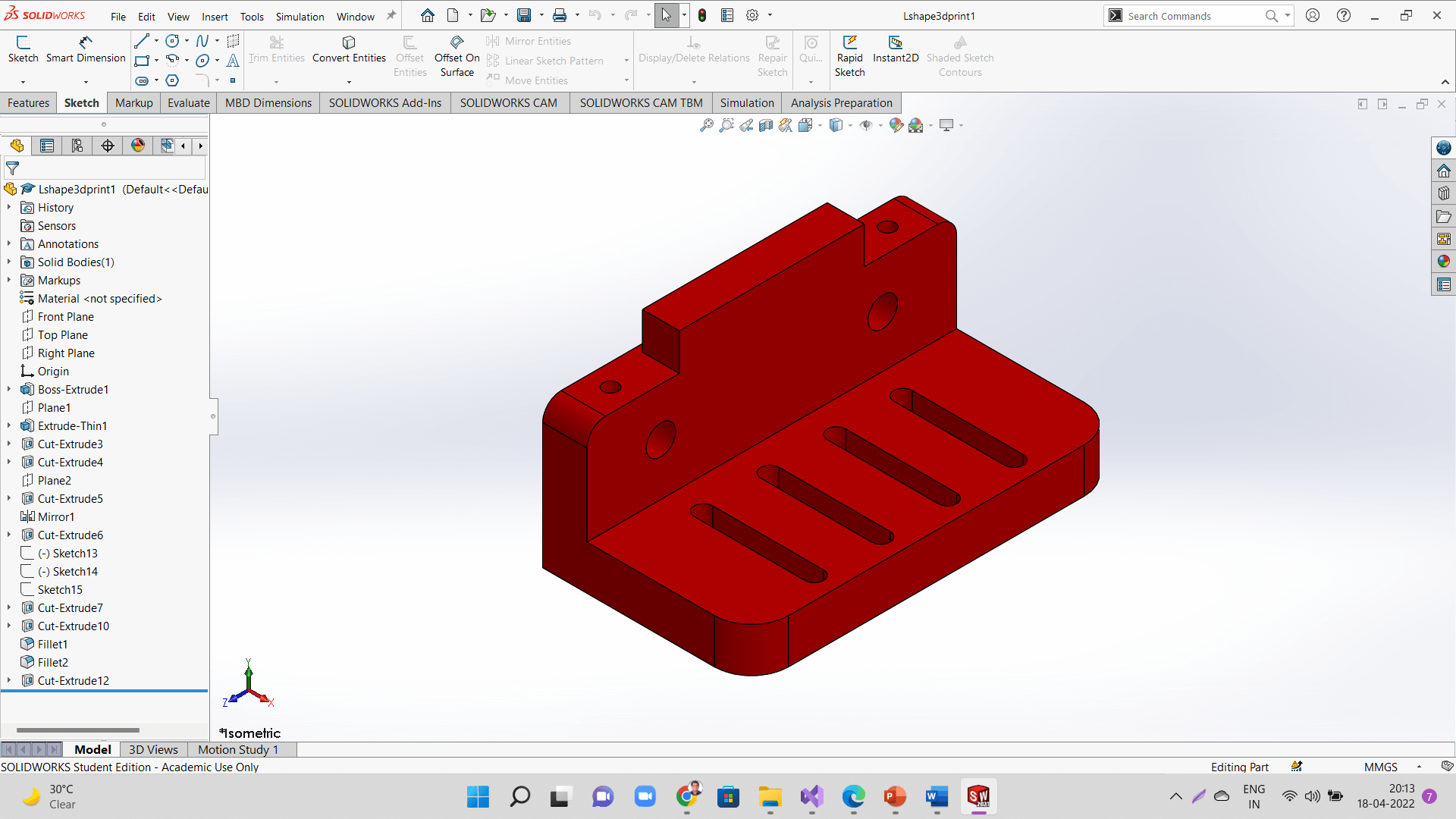 |
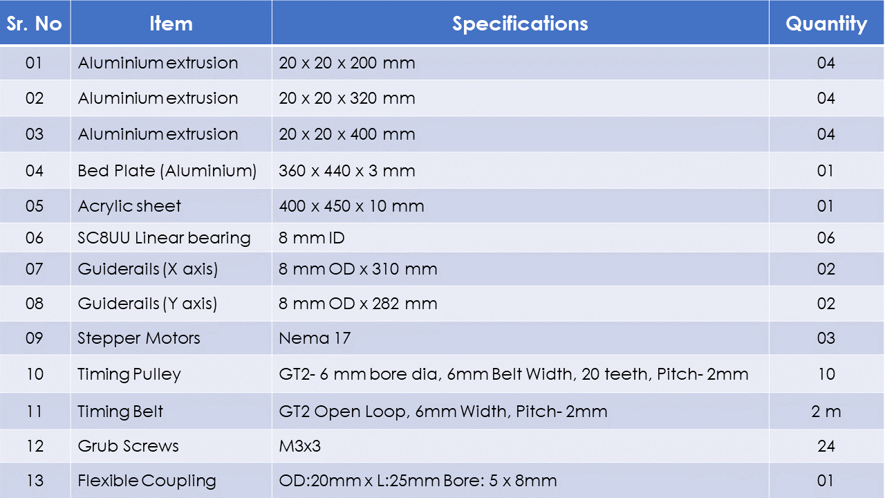
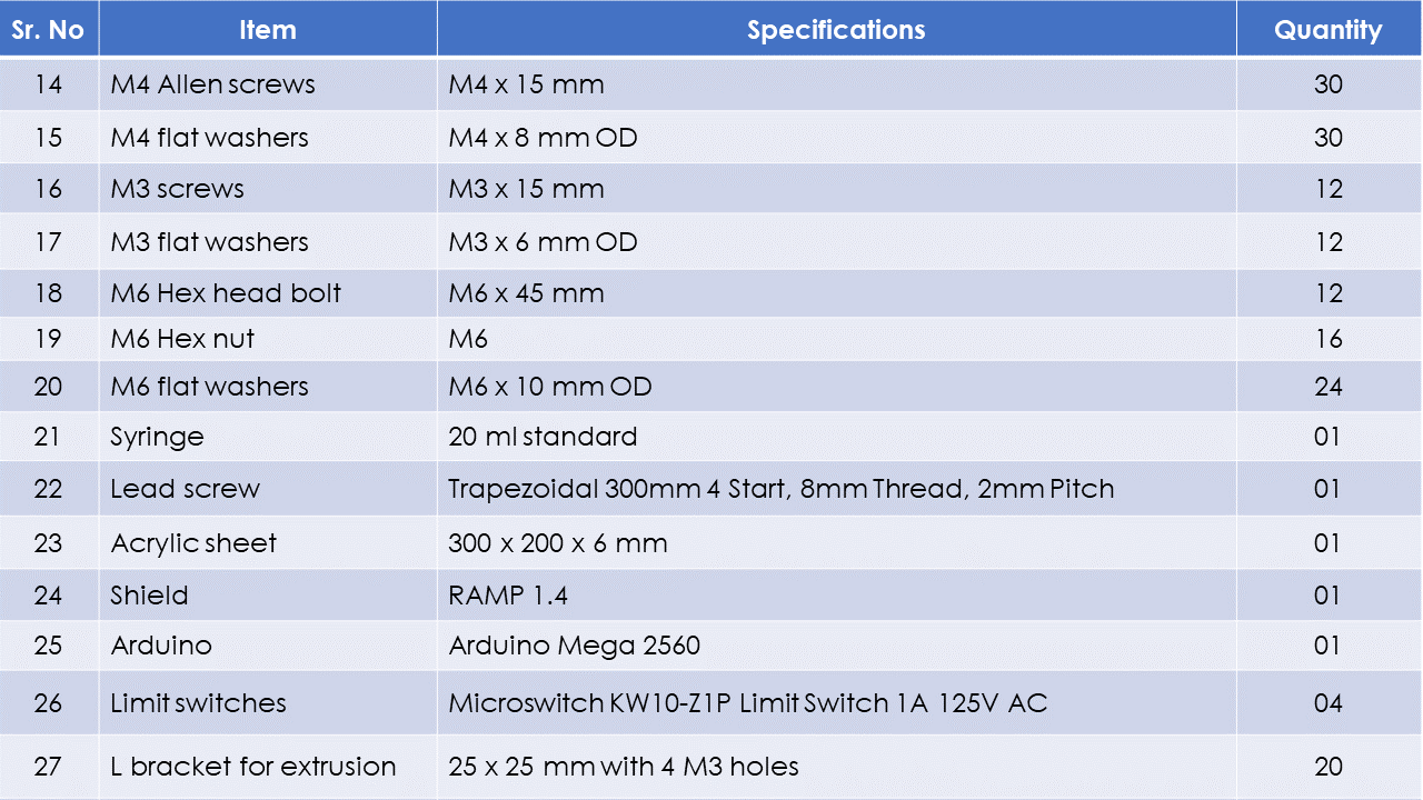
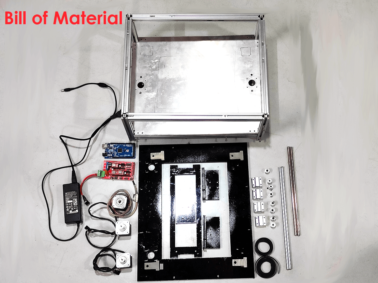
I contributed in generating and documenting engineering and manufacturing Bill of Material of our entire machine. We did not include wires and power supply accessories in to the BOM.
Bill of Material:
 |
 |
Click here to go back to the top
Fabrication
1. Laser Cutting
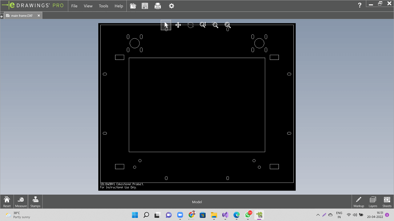
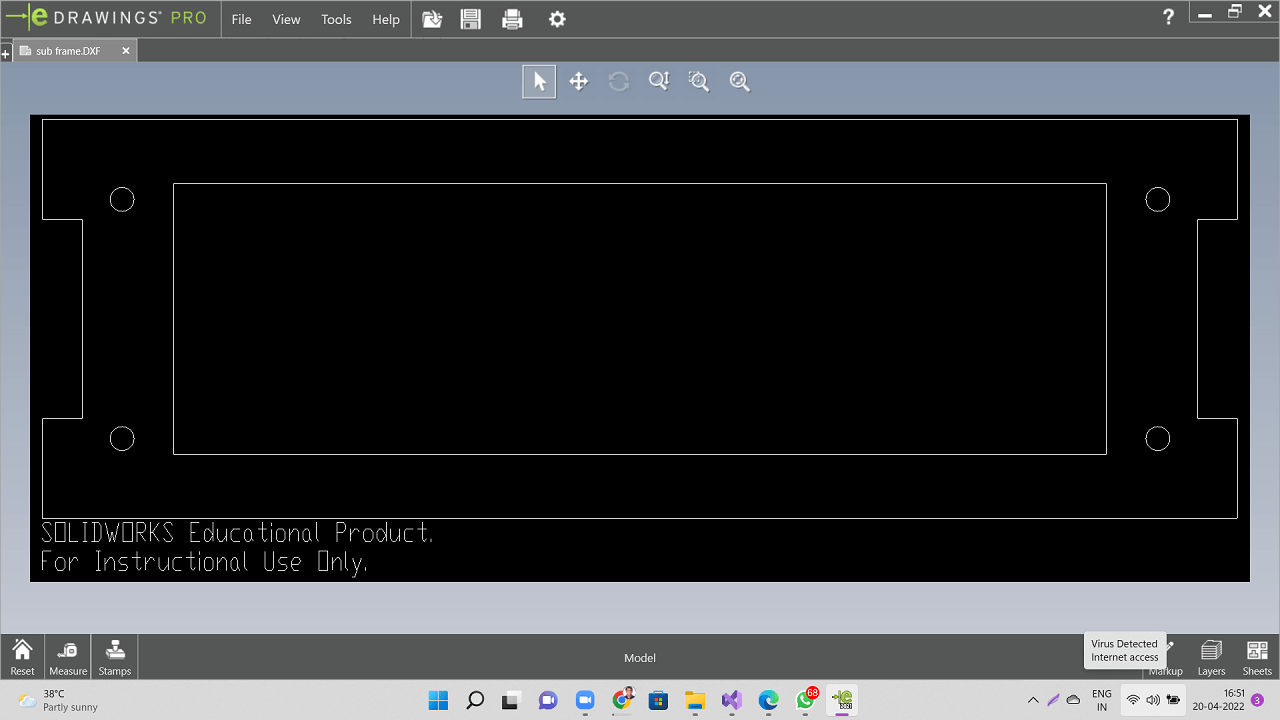
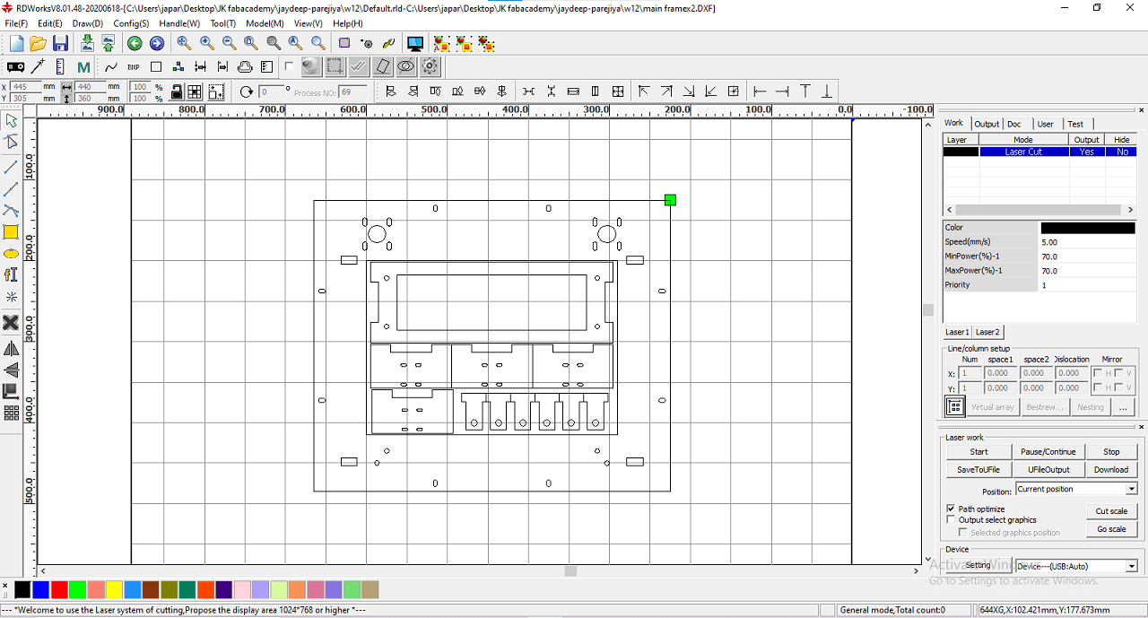
Jaydeep took the responsibility of fabrication. I contributed in providing him the dxf files and also helping him We laser cut the main frame, middle frame plates. We also had cut the L shape bracket and T-slot brackets using the laser cutting.
 |
 |
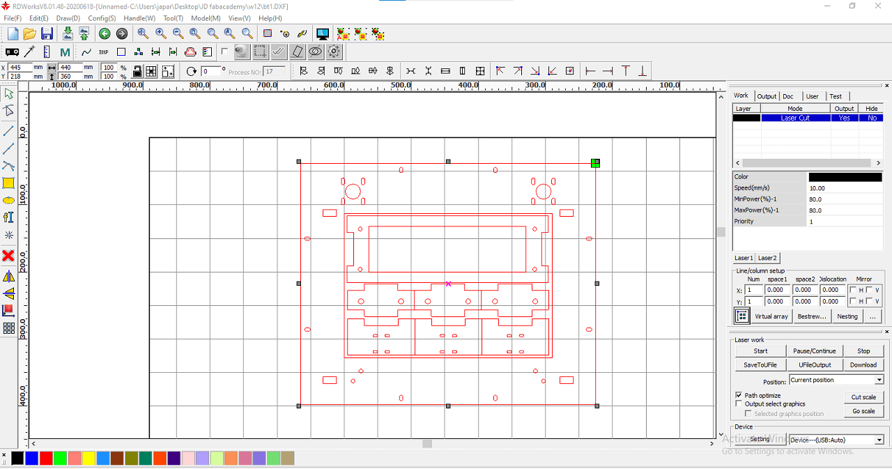
Jaydeep worked in RDworks nesting to generate files for laser cutting
 |
 |
2. 3D Printing
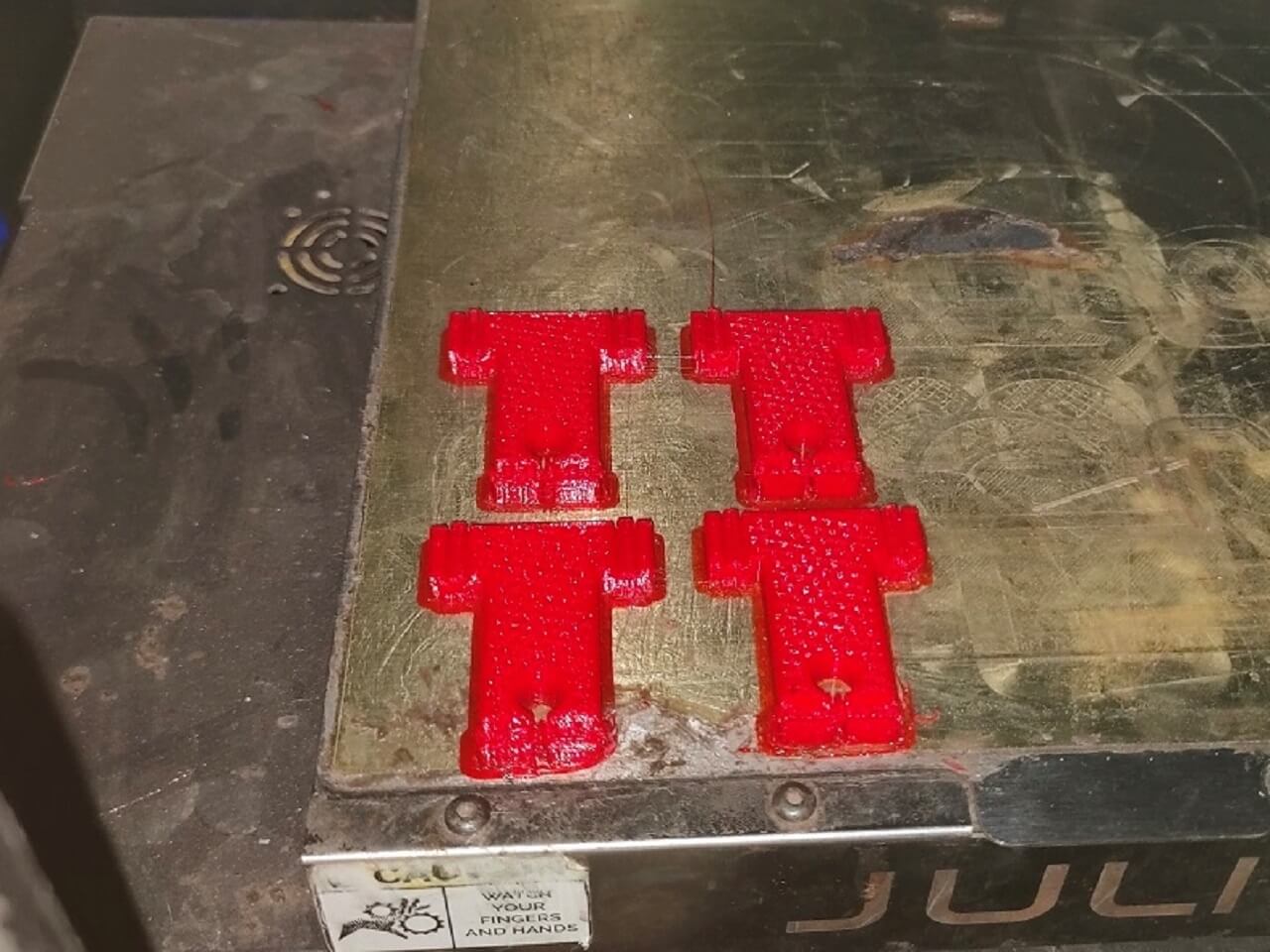
I contributed in setting up the 3D printing along with Kiran sir, who designed these parts quickly. We 3D printed the L shape bracket for mounting linear bearings for Y axis and also T holders for guiderails after we found issues in assembly later. We have mentioned the issue later in the document below.
 |
 |
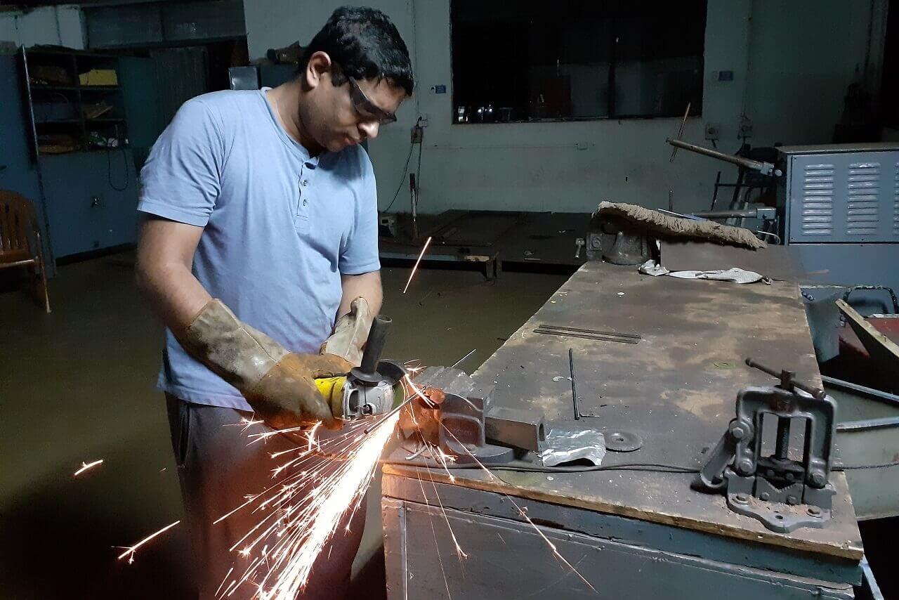
3. Cutting and Grinding
We needed to cut the guiderail shafts and one aluminium extrusion as per our design, we used a power cutting and grinding tools for these operations, we also provided a chamfer on the edges on guiderail shafts. I contributed in providing these dimensions and cutting one shaft. Fenil, Jaydeep and Ashish did the rest.
|
Click here to go back to the top
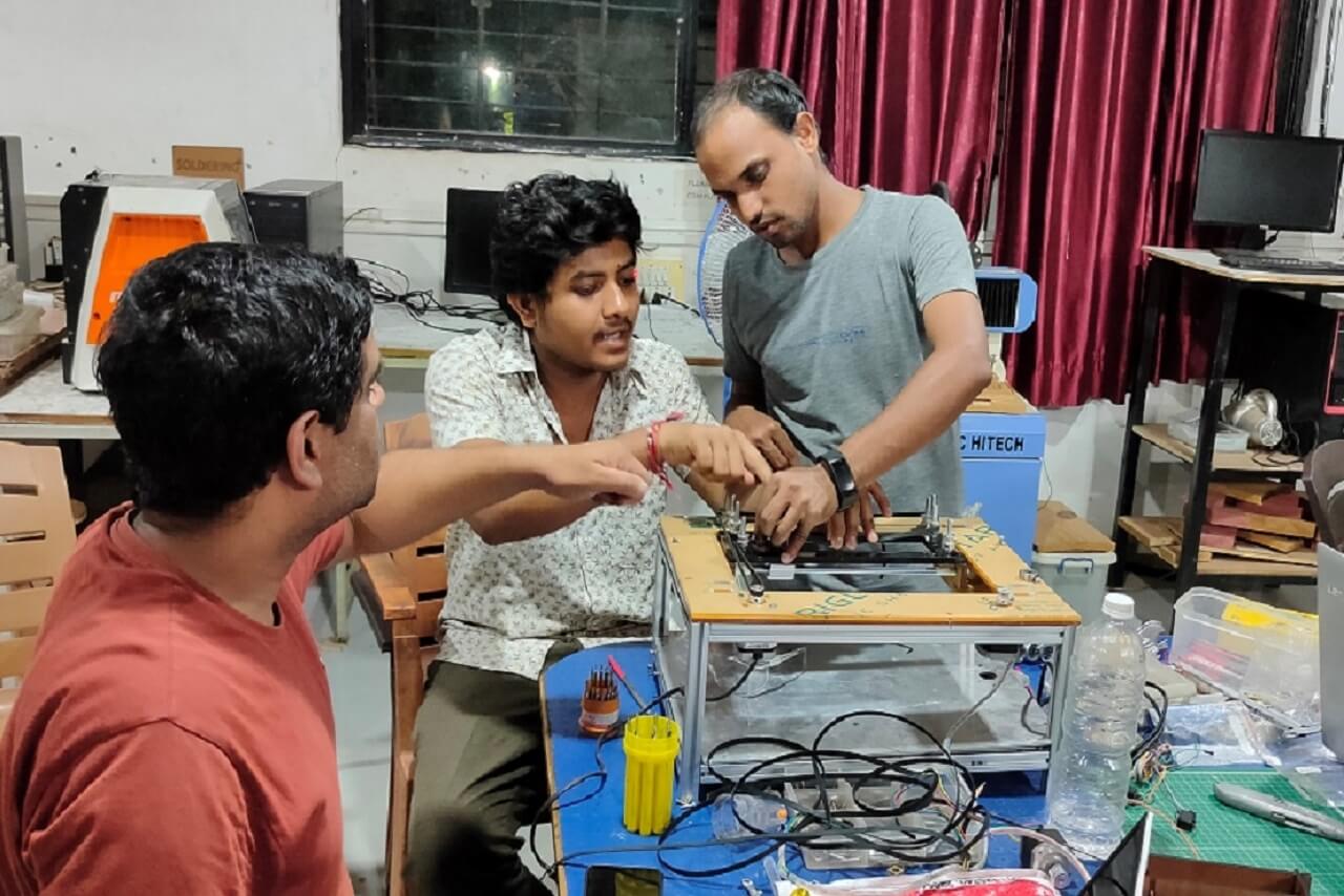
Assembly
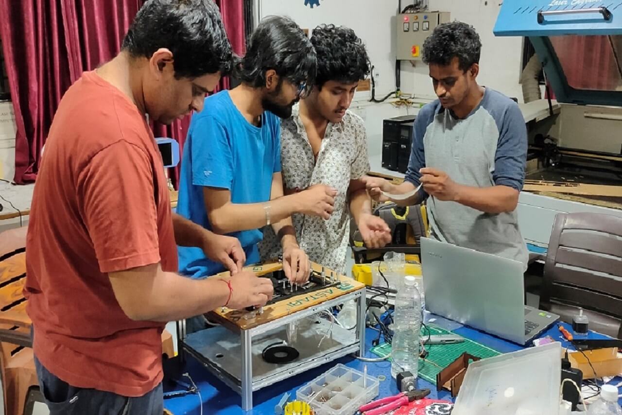
Once all the parts were in place (either purchased, laser cut or from our lab inventory), we started to assemble the machine. Following is a picture of all the material in place. I contributed all through the process of assemblying the machine.
 |
We started with building the base frame with the aluminium extrusions we had. We levelled them as we were assembling them. We started assembling the main frame sub-assembly and middle frame sub-assembly.
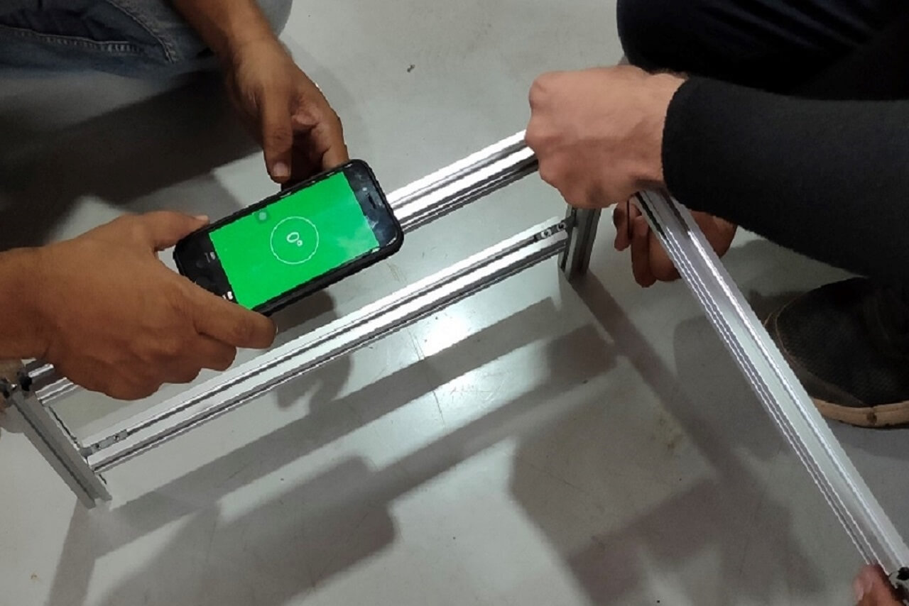 |
 |
The T-slots we had cut on laser were not cut as per the designed specifications. So, they were not sitting in place. We fixed them using the glue just to check if the assembly works. This was not a permanent solution though.
|
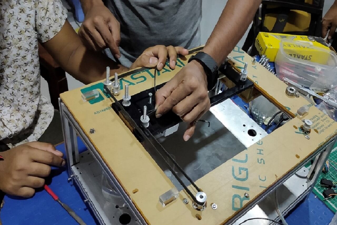 |
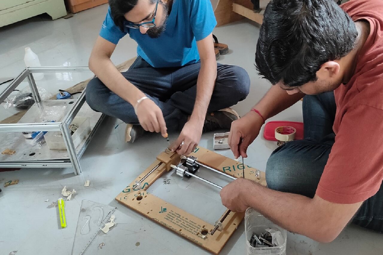
We started assembling all the parts to the assembly, like stepper motors, pullies, timing belt, hardware, etc.
 |
|
 |
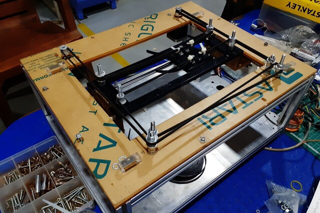 |
However, during the assembly process, we had fitment and alignment issues with T slot brackets that hold the guiderails along the Y axis, L shape bracket that hold the linear bearings. The T-slots cut by laser were not having proper press-fit and the L-shape bracket was not at perfect 90 degrees. Apart from that these guiderails had single linear bearing each, so the movement of the mechanism along the Y axis was not happening smoothly, it was wobbeling too much.
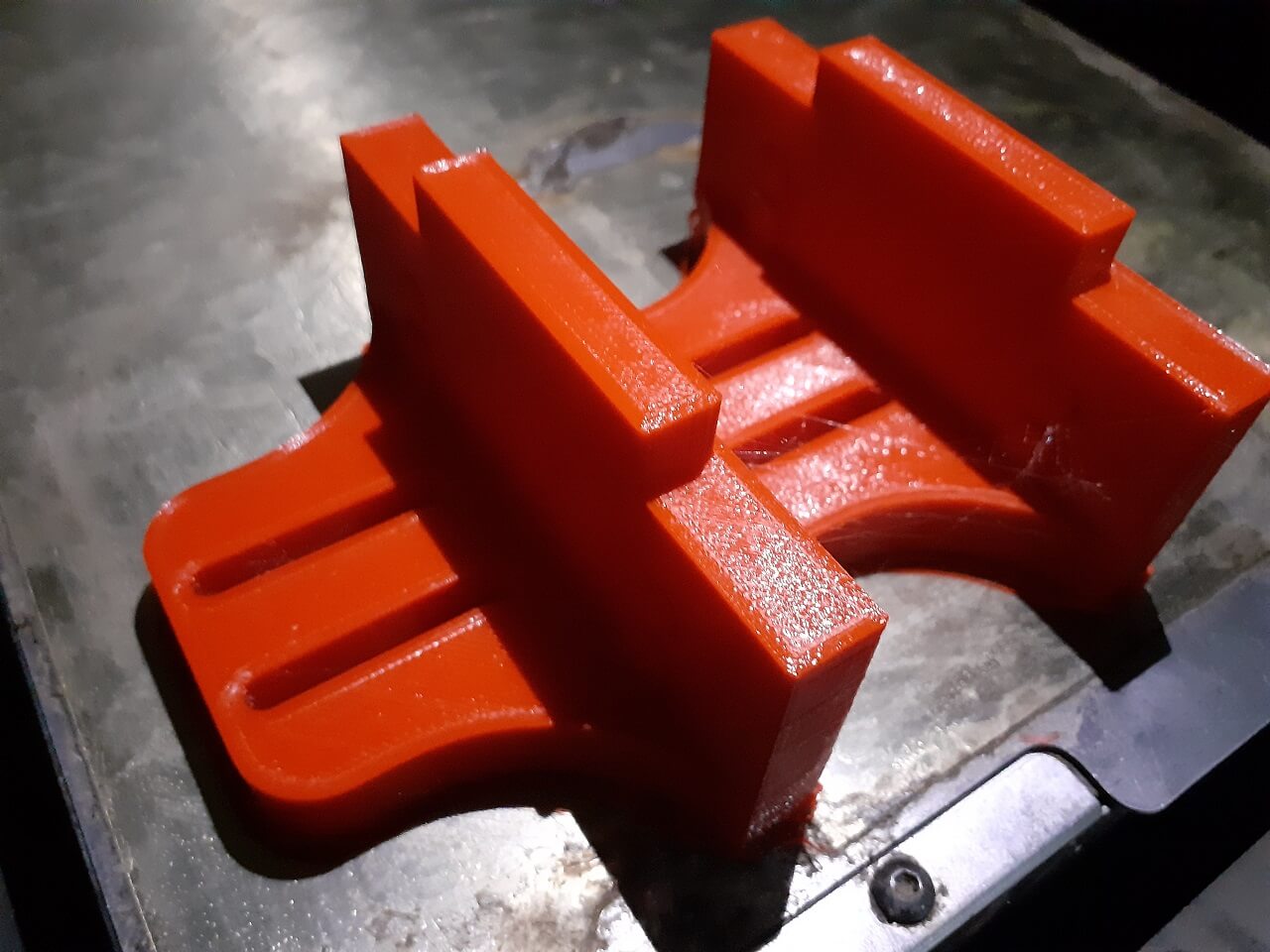
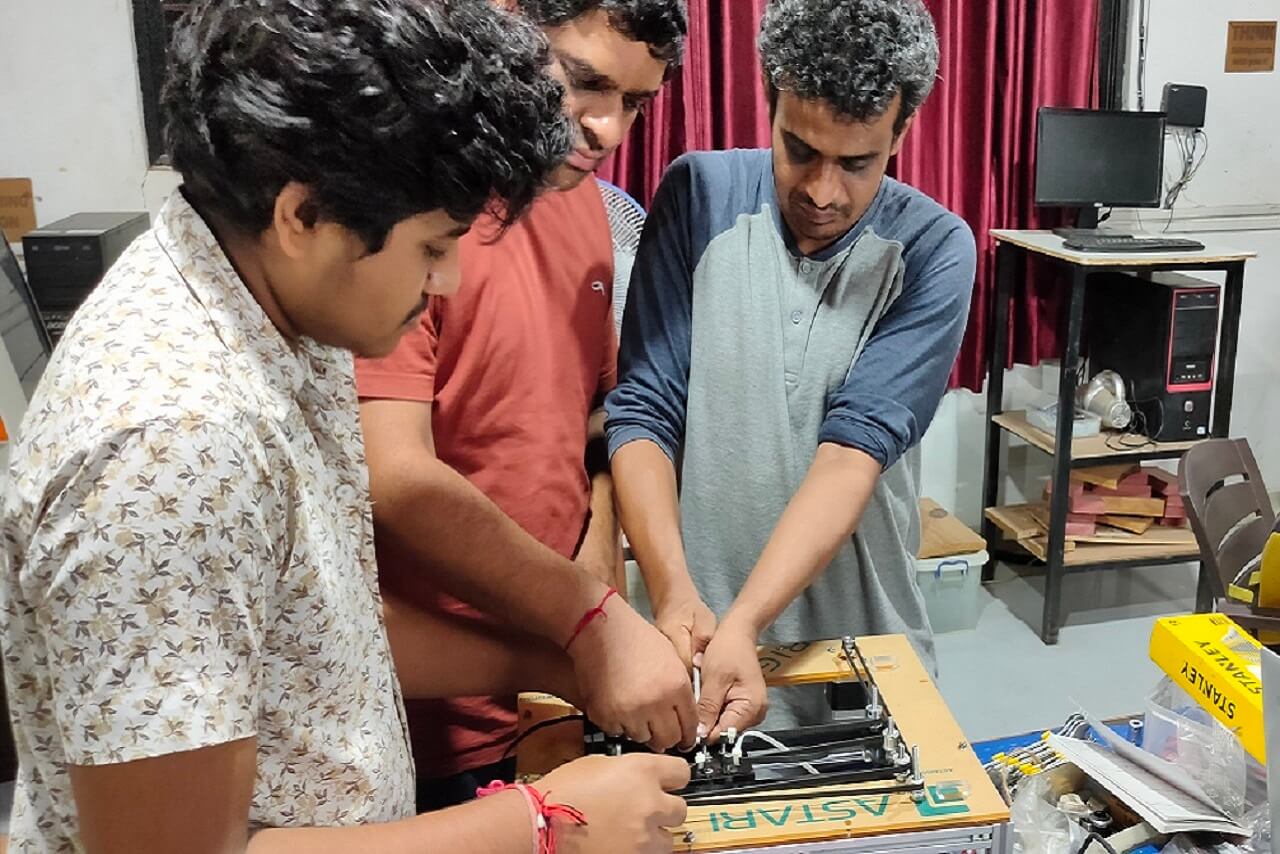
So we decided to go for 3D printing of T brackets for holding guiderails and L bracket for mounting linear bearings. Also we added an extra bearing each to the Y-axis guiderails as shown below.
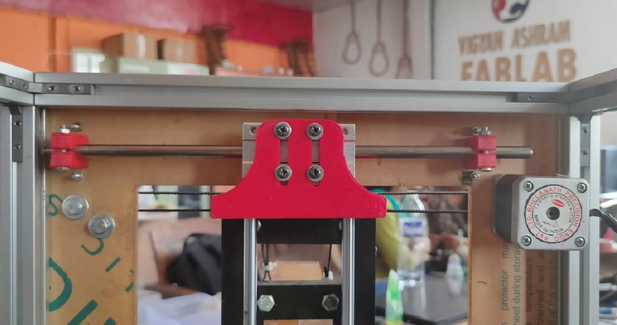 |
This major hurdle in building our machine was thus removed successfully after implementing this solutions. The mechanism was working perfect now.
Actuation
After we replaced these parts and adding extra bearings, we re-assembled all the parts again and we were able successfully actuate the mechanism as shown in the video below. It works pefrectly fine on all 6 different movements.
Click here to go back to the top
Electronics
Vrushabh and Devesh took responsibility of electronic and software designs for the machine, out of, which Vrushabh focused on the electronic part of the machine that includes testing and connecting various electronic parts such as stepper motors, drivers, shield, controller board, end switches, cables, etc. and integrating all of this with the software part of the machine.
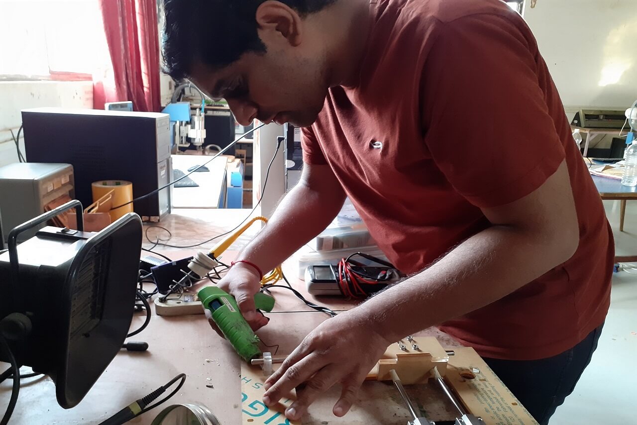
I contributed in working with Vrushabh in testing stepper motors with stepper drivers. I also worked with him on making Ramp 1.4 connections and run motors through Ramp and arduino mega
A. Electronic Hardware
Selection of the electronic components:
We refered diferent CoreXY based CNC plotters, they all have used the below components specifically when using Marlin as a firmware-
- Stepper motor
- Stepper motor drivers
- Driver shield
- Control board
- End Stopper switch
- External power supply
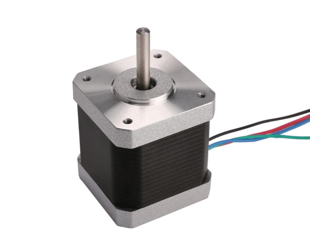
Selecting the stepper motors and stepper drivers:
Based on the requirements of the mechanical design of the machine, we selected Nema 17 stepper motor with 5.5 kg-cm torque to drive the machine axis. We selected two such motors for running XY axis in CoreXY and one for extruder.
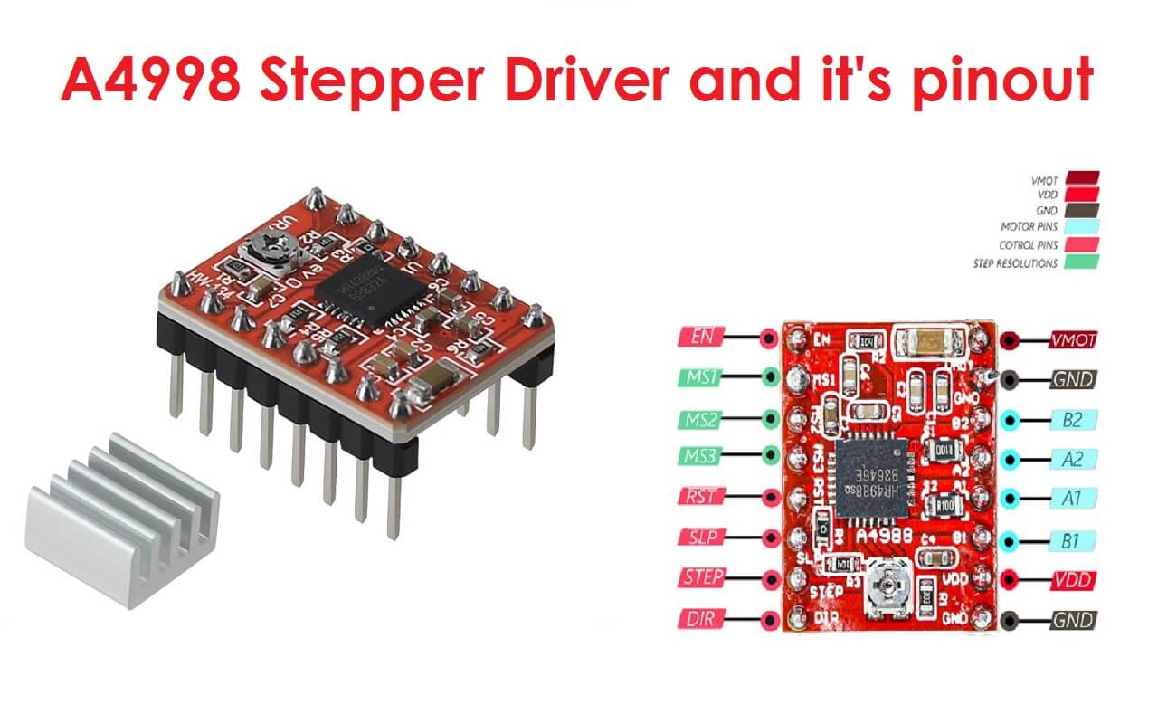
For running the stepper motors, we required stepper drivers. For, which we had multiple options. However, considering the driver configuration availability in Marlin firmware and the inventory we had in our lab, we went with A4988 as a motor driver.
 |
 |
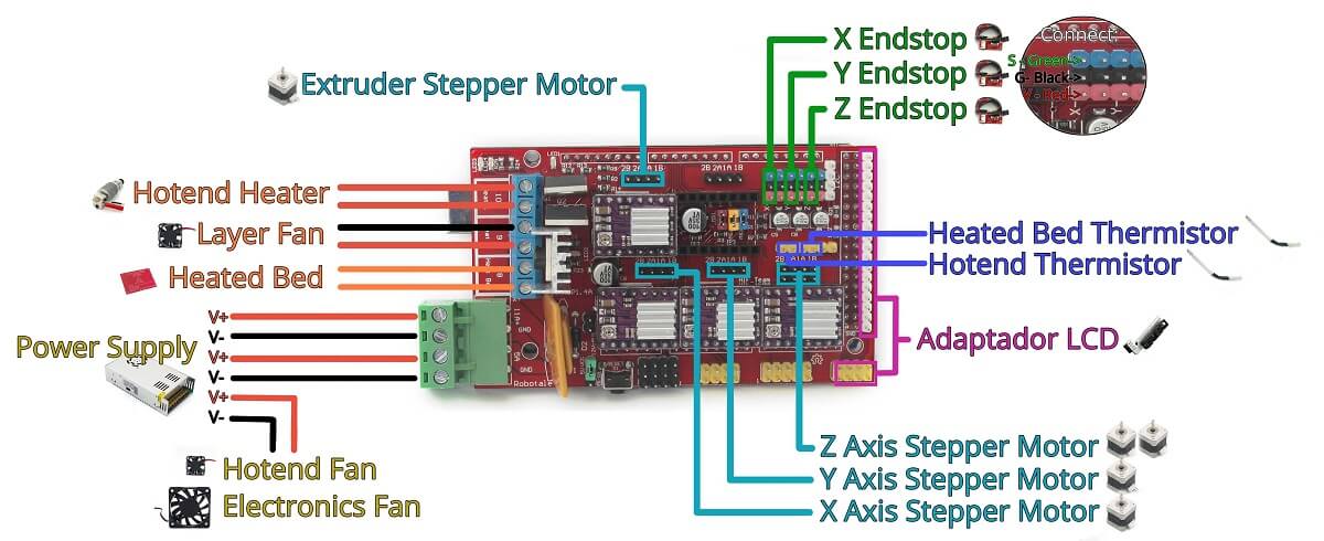
Selecting the CNC stepper driver shield and controller board:
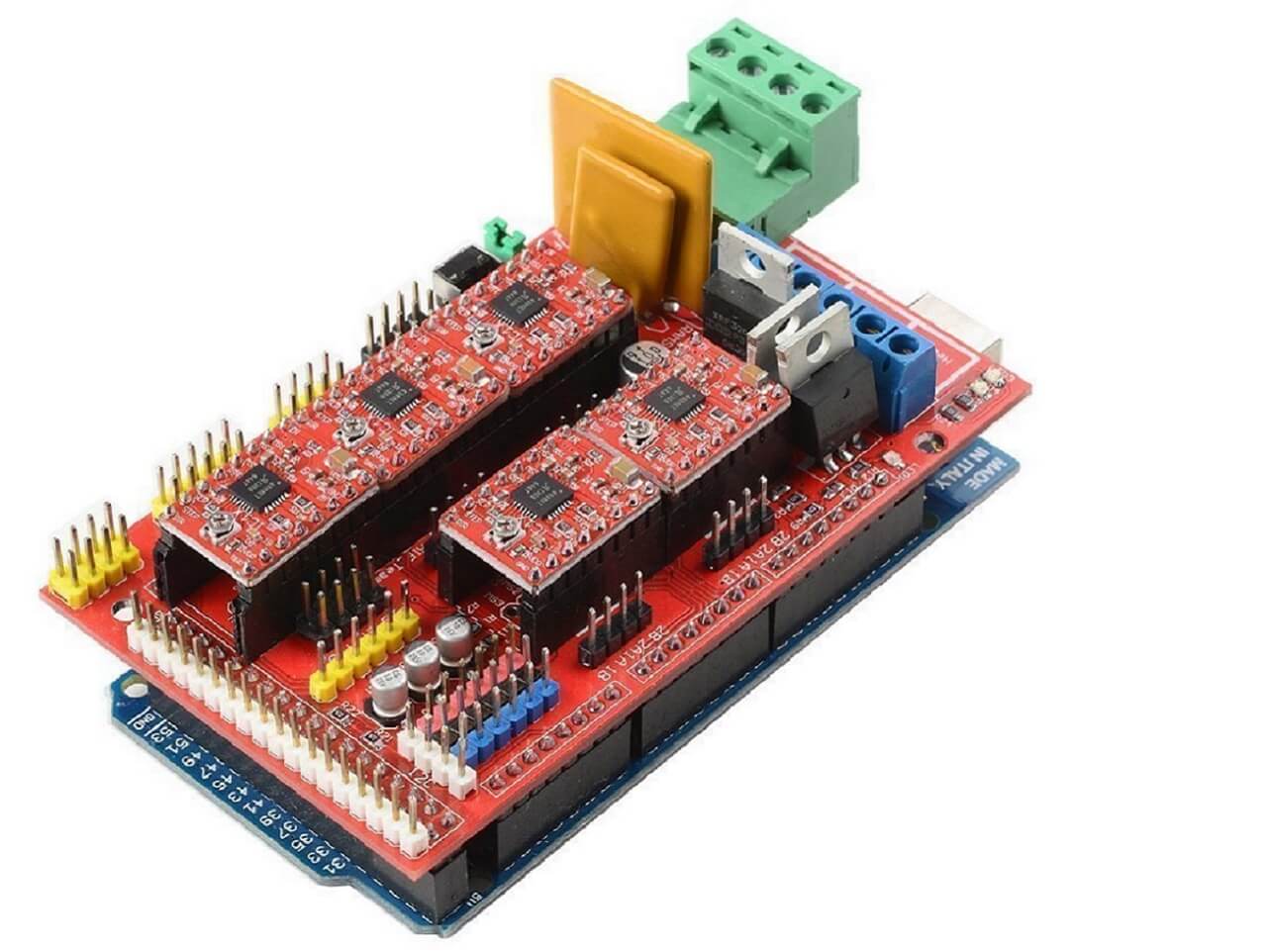
There are so many types of CNC stepper driver shields available, out of, which we had in our lab, Arduino CNC V3 shield, Ramp MKS 1.4 V, and Ramp 1.4 CNC shield. We selected Ramp 1.4 CNC shield because of its strong community support and availability of multiple such shields in our inventory.
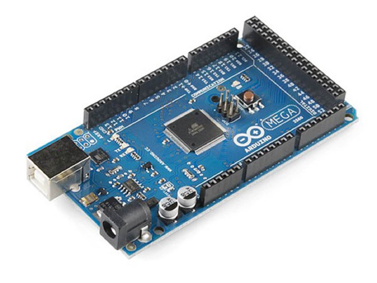
As the Ramp 1.4 boards are built for Arduino Mega 2560, we had no other option for selecting the controller board than Arduino Mega 2560.
 |
 |
Selecting the power supply:
As per the requirement of current consumption and voltage requirement for electric components for our machine, we chose 12V 5A power supply for powering up the machine.
Testing of electronic components:
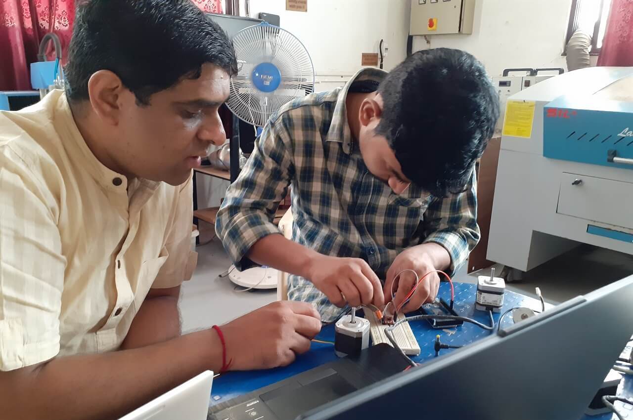
1. Testing stepper motor and stepper motor drivers.
We wanted to test the stepper motor before setting up our electronic for our printer. As we were going to use Marline firmware and it is not configured yet, so we decided to test the stepper motor first. We started with testing individual stepper motors for, which we referred the blog from last-minute engineers. We tested all the motors and drivers and they were working fine.
 |
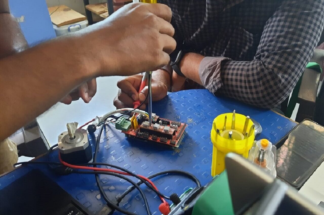 |
2. Testing stepper motors with Ramp 1.4 shield.
After testing motors individually, we tried to run them through Ramp 1.4 shield. For that, we referred this site for more details on Ramp 1.4. We referred this site for understading Ramp 1.4 connections.
 |
we assembled the motor drivers on the Ramp, attached the 12V 5A supply to the board and set everything ready to test. We used the same test code to try to run the motor on-ramp shield after checking the dir and step pins from the schematic diagram of the ramp board for the X-axis motor.
To know the pinout for X-axis, we referred this site for more details. For X axis- it is A0 and A1 for dir and steps respectively. After we made the connections, we uploaded the code but it did not work, the motors did not run. Then we checked for the power supply for Ramp board, arduino mega connections and also did the cable output continuity testing. But the motors did not run.
After several trials to run the stepper motor on Ramp 1.4, finally we found that Ramp library is missing in the arduino code and it needed to be installed as well. We got the Ramp library from this site. Sign in on github in case the page shows 404 error. We used the arduino code from this site and made custom changes to it according to our requirements to run all the motors. Sign in on github in case the page shows 404 error. All these steps helped us in running the steppers using ramp board successfully before configuring the hardware with Marlin.
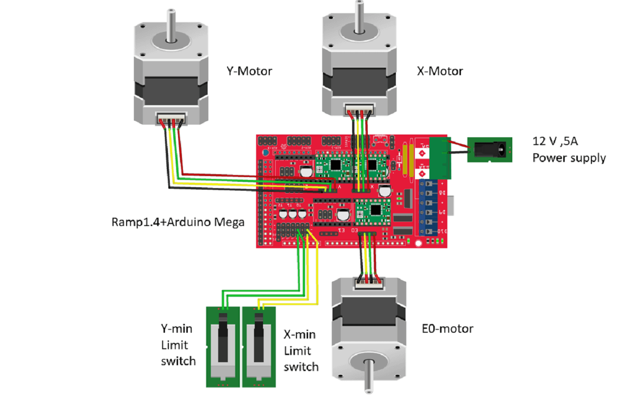
3. Assembling limit switches and circuit diagram.
This is our final circuit digram of the electronic on our machine. We will discuss more about setting home position of the machine using limit switches in the subsequent sections below.
 |
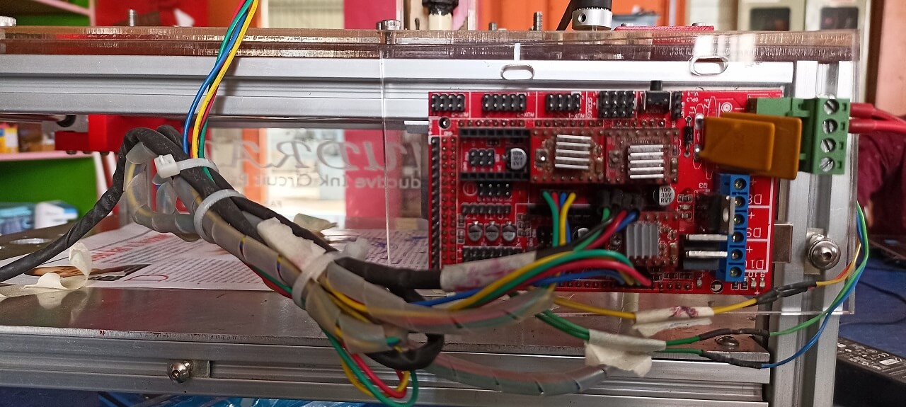
4. Connections and routing on the machine.
For final testing of machine, we assembled all electronic hardware components on the machine as shown in the image below. We then uploaded the marline code in Arduino mega board. Important note: Remove the ramp shield during uploading the code.
 |
Go to our machine site for more details on Firmware and Extruder design.
Final video linkTest Runs:
Click here to go back to the top
Original Files for download:
Click here to download CAD files.
What went well
In group assignment- We learned a lot from our mistakes and we corrected them immediately as we realized them. We worked as a team, we had a brainstorming session to decide upon the machine, mechanism, parts required, etc. We were able to work collaboratively and concurrently as a team.
In individual contribution- I was able to contribute to mechanical design including selection of mechanism, modeling, assembly in solidworks, contributing in fabrication, assembly, electronics hardware portion and test runs.
What went wrong
In group assignment- We made a lot of mistakes, first we used single bearing for the guiderails on Y axis, when its length was large enough to cause the frame to wobble. We also, used laster cut T-slot holders for guiderails, because of their fitment issues, the guiderails were bent and the XY mechanism's motion was not smooth. In electronics, we also did mistakes, a couple of times the motor drivers got burnt, then we also took some time to set-up marlin firmware. In extruder design, we tried different options for conductive printing like clay, ink, etc.
In individual contribution- I missed to verify the length of guiderails using the solidworks assembly, after actual assembly, I realized that length of guiderails were more and they needed to be cut further to avoid the interference.
Learning Outcomes
- I learned the importance of regular and timely communication within the team while working on concurrent engineering projects.
- I learned basics of various mechanism, different parts used in mechanical design, how to assemble them.
- I learned the accuracy of 3D printed parts over the laser cut parts. Next time, I will plan my BOM accordingly.
- I learned a lot in electronics this time- setting up stepper motors using shield, their drivers, connections, marlin firmware and Pronterface interface.
- I learned different conductive materials that are easily available at home, which can be used to create circuits.