Assignment#5: 3D Scanning and Printing
This assignment is about documenting what I learned in 3D scanning and printing that includes difference between additive and subtractive manufacturing processes, constraint and design rules for 3D printing, different materials and processes used in 3D printing, different 3D printers, software and 3D scanning. I have also documented how I used 3D printing machine and 3D scanner to work on my individual and group assignment. I also was able to 3D print my own 3D scanned model. I have always been in love with 3D printing as a hobbyist. Now, I am excited to use 3D printing some parts required for my final project. I am also documenting what went well, what went wrong, how I would do things differently in next assignment and my learning outcomes.
My Hero shots for this week
Click here to go back to the top
3D Printing
3D printing, or additive manufacturing, is the construction of a three-dimensional object from a CAD model or a digital 3D model. The term "3D printing" can refer to a variety of processes in which material is deposited, joined or solidified under computer control to create a three-dimensional object, with material being added together (such as plastics, liquids or powder grains being fused together), typically layer by layer.
In the 1980s, 3D printing techniques were considered suitable only for the production of functional or aesthetic prototypes, and a more appropriate term for it at the time was rapid prototyping. As of 2019, the precision, repeatability, and material range of 3D printing have increased to the point that some 3D printing processes are considered viable as an industrial-production technology, whereby the term additive manufacturing can be used synonymously with 3D printing. One of the key advantages of 3D printing is the ability to produce very complex shapes or geometries that would be otherwise impossible to construct by hand, including hollow parts or parts with internal truss structures to reduce weight. Fused deposition modeling (FDM), which uses a continuous filament of a thermoplastic material, is the most common 3D printing process in use as of 2020. Click here to read more.
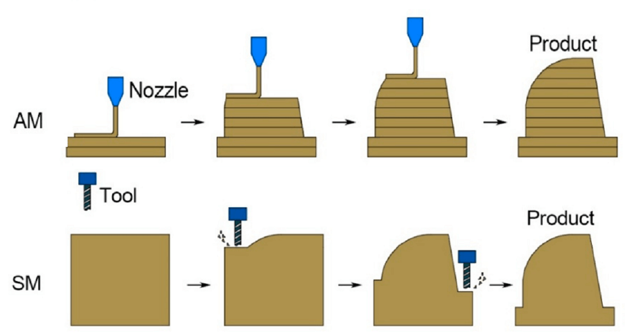
Additive vs Subtractive manufacturing
| Parameters | Additive manufacturing | Subtractive manufacturing |
|---|---|---|
| Principle | Involves adding layers of material to create an object | Removes material from an object |
| Process | Processes include 3D printing, direct digital manufacturing, rapid prototyping or additive and layered fabrication | The process is either by: manual removal, traditional machining or CNC machining |
| Equipment and tools | Uses computers and specialist 3D printing equipment to create products or prototypes | Uses computers and robotics to assist standard machining processes, e.g., turning, drilling or milling |
| Achievable complexity | Can produce parts with highly complex and intricate geometries, even better than 5-axis CNC machining. Intricate and hollow objects can easily be built up in layers | Better suited to relatively simple geometry. Milling undercuts and intricate shapes can be difficult |
| Producible features | Cannot produce features such as holes and threaded features effectively | Effectively creates holes and threaded sections. |
| Producible sizes | Best suited for smaller items or parts, especially in plastic | Best suited for manufacturing voluminous items and parts, especially in metal |
| Properties of parts produced | Parts produced may have insufficient mechanical properties. Because the parts are created layer by layer, structural weaknesses arise between these layers, thereby compromising specific properties. | Parts produced may have excellent mechanical and thermal properties. |
| Accuracy | Can achieve less dimensional accuracy. The most accurate AM process, SLM/DMLS, can produce tolerances as tight as 0.100 mm. | Can achieve greater dimensional accuracy. Tolerances as tight as 0.025 mm are possible. |
| Production materials | Works predominantly with plastics and to a small extent, metals. | Works with a wide range of materials, including plastics, metals, wood, foam, glass, and stone. |
| Finishing | Parts produced always require finishing processes. The layering often leaves a slightly 'stepped' or rough surface which needs to be finished post- printing by sanding or blowing | Parts produced may not require finishing. A variety of surface finishes can be machined, including smooth, stepped, mottled, etc. |
| Setup | Requires minimal setup which results in shorter time per part, from design to production. After designing a CAD model of the part and converting it, all you need to do is setup the feedstock material, and the 3D printer does the rest. | Requires more effort and time in setting up. In CNC machining, for example, after designing a CAD model and converting it to G-Code, you need to set several aspects and parameters of the CNC machine. These include placing the workpiece on the work table, selecting and preparing the appropriate cutting fluid, selecting and affixing the cutting tool, and setting the right speed, feed, and depth of cut. |
| Scalabitlty | Cost of production is directly proportional to production quantity. As production quantity increases, however, production costs rise significantly. | Cost of production is inversely proportional to production quantity. As production quantity increases, production costs reduce. |
| Speed and cost | Faster and less expensive for geometrically small parts, plastics, and small production runs. For large sized object, 3D printing can be a slow process | Best suited for manufacturing voluminous items and parts, especially in metal. Faster and less expensive for relative large parts, metals, and large production runs. However, quite expensive for than additive mfg for low volume |
 |
3D Printing Processes
1. Photopolymerization
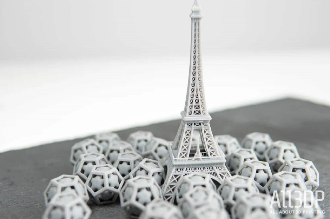
Photopolymerization 3D printing technology encompasses several different processes that rely on the same basic strategy: a liquid photopolymer contained in a vat (or tank) is selectively cured by a heat source. Layer by layer, a 3D physical object is built until completion.
There are multiple types of curing devices in addition to the oldest technique, which is based on lasers. Digital Light Processing projectors and even LCD screens are now a popular way of photopolymerizing materials given their low cost and very high resolution. One of the advantages of these two techniques compared to lasers is their ability to simultaneously cure a full layer of resin, whereas the laser needs to progressively illuminate the whole surface by drawing it. The most popular vat photopolymerization 3D printing technologies include the following:
StereoLithogrAphy (SLA): SLA is also known as SL, optical fabrication, photo-solidification, or resin printing. During the SL manufacturing process, a concentrated beam of ultraviolet light or a laser is focused onto the surface of a vat filled with a liquid photopolymer. The beam or laser is focused, creating each layer of the desired 3D object by means of cross-linking or degrading a polymer. Please see the left image below.
Digital Light Processing (DLP): In DLP 3D printing process, a digital projector screen is used to flash a single image of each layer across the entire platform at once. Because the projector is a digital screen, the image of each layer is composed of square pixels, resulting in a layer formed from small rectangular bricks called voxels. DLP can achieve faster print times for some parts, as each entire layer is exposed all at once, rather than drawn out with a laser. Please see the right image below.
 |
Advantages of Photopolymerization
- High resolution of printing when compared to FMD technology
- Small assortment of materials available and some materials are toxic
- Support structures for overhangs are required
- end products are waterpermeable, you should not use a dishwasher to clean them
- Objects can be heated to the temperature of 48 deg C, not higher, as they start changing their properties
- High cost of photopolymer resins
Advantages of Photopolymerization
- Small printing speed, especially when compared to SLA printers
- The end product has a smooth and even surface
- You can print highly detailed items with complex geometry and different characteristics the object can be firm or flexible, transparent or opalescent, multicolored or monotonous, etc.
- Readymade product is easy to post process - it can be painted, cut, parts can be glued together, etc.
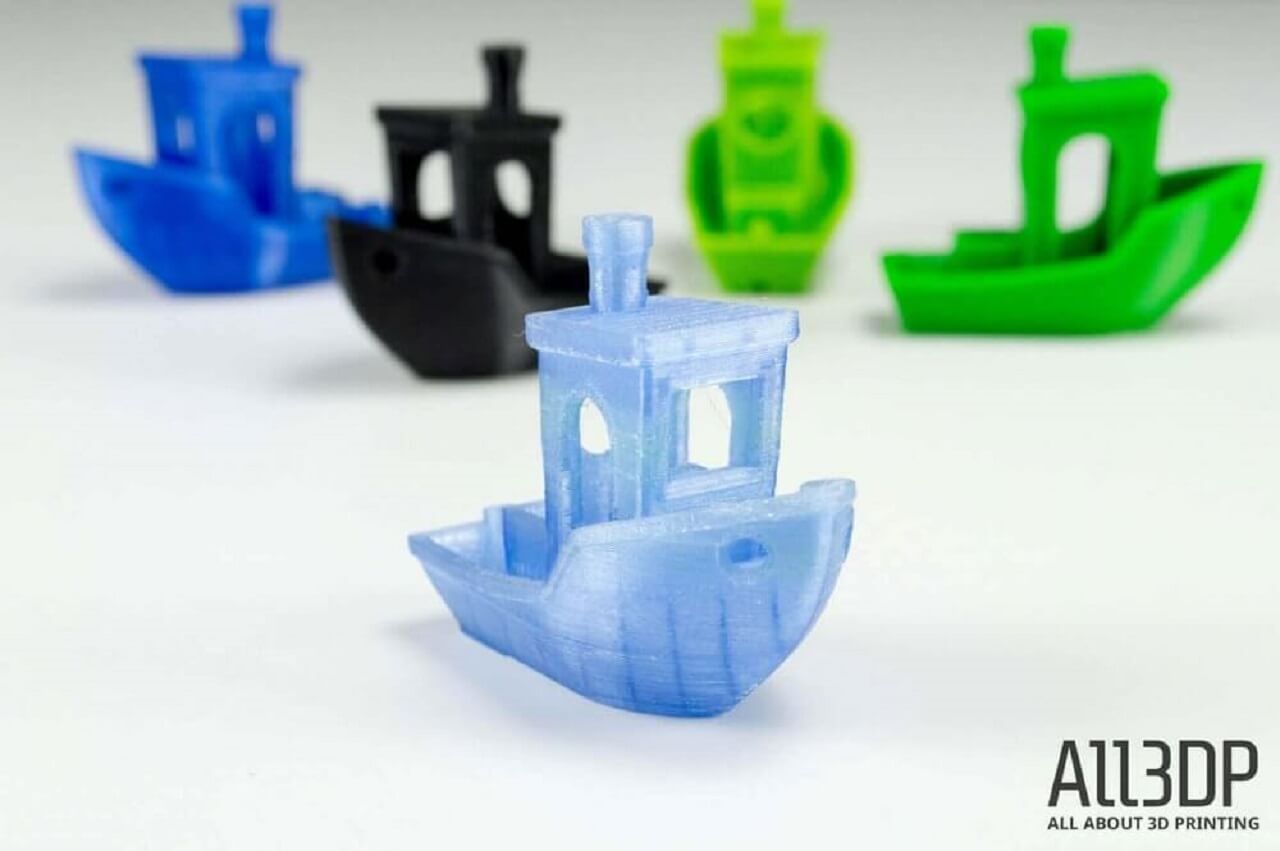
2. FDM (Fused-Deposition Molding)
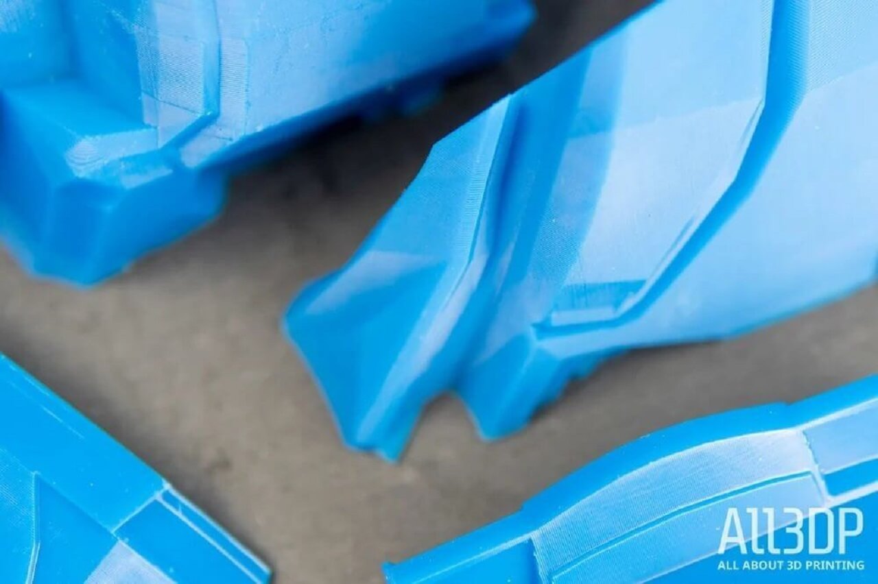
FDM- Material Extrusion 3D printing technology uses a continuous filament of a thermoplastic material as a base material. The filament is fed from a coil, through a moving heated printer extruder head, often abbreviated as an extruder. The molten material is forced out of the extruder's nozzle and is deposited first onto a 3D printing platform, which can be heated for extra adhesion. Once the first layer is completed, the extruder and the platform are parted away in one step, and the second layer can then be directly deposited onto the growing workpiece. The extruder head is moved under computer control. At least three axes are required for the extruder to move in Cartesian architectures, but polar and delta systems are also becoming increasingly popular. One layer is deposited on top of a previous layer until the objects fabrication is complete. The different Powder Bed Fusion methods notably include:
Material extrusion is known as Fused Filament Fabrication (FFF) and is one of the most popular processes for hobbyist-grade 3D printing. The proprietary term Fused Deposition Modeling (FDM) was coined by S. Scott Crump in the late 1980s and was commercialized in 1990 by the Stratasys company. With the expiration of this technologys patent, there is now a large open-source development community called RepRap, as well as commercial and DIY variants, which utilize this type of 3D printing technology. This has led to a measurable price decrease. However, the material extrusion technique has dimensional accuracy limitations and is very anisotropic.
A wide variety of materials can be extruded, the most popular being thermoplastics, such as Acrylonitrile Butadiene Styrene (ABS), PolyLactic Acid (PLA), High-Impact Polystyrene (HIPS), Thermoplastic PolyUrethane (TPU), aliphatic PolyAmides (PA, also known as Nylon), and more recently high performance plastics such as PolyEther Ether Ketone PEEK or PolyEtherimide PEI. Additionally, paste-like materials such as ceramics, concrete and chocolate can be extruded using this 3D printing technique. Please see the image below.
 |
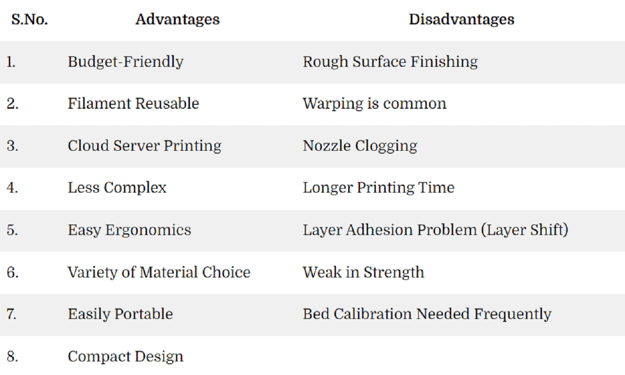
Advantages and Disadvantage of FDM
 |
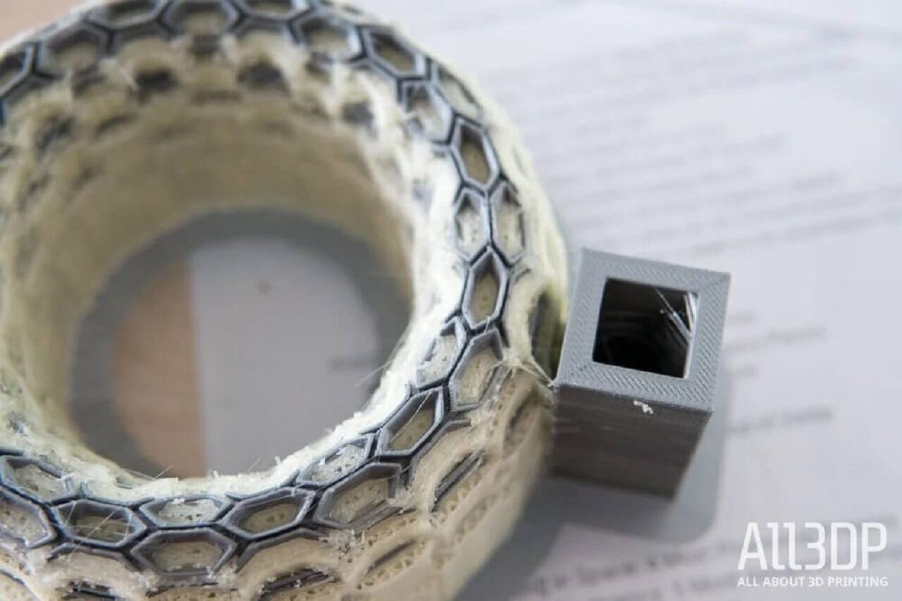
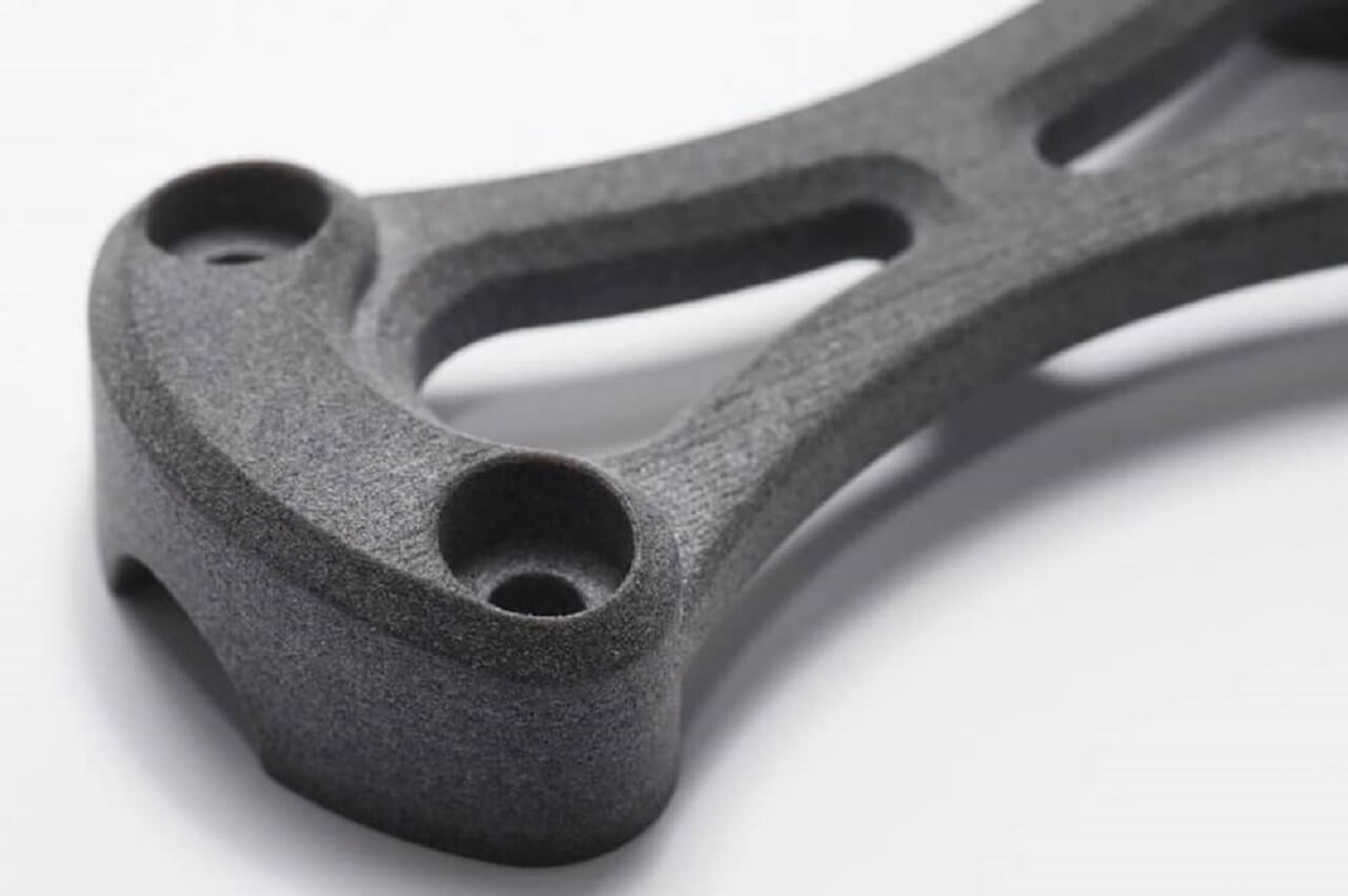
3. Powder Bed Fusion
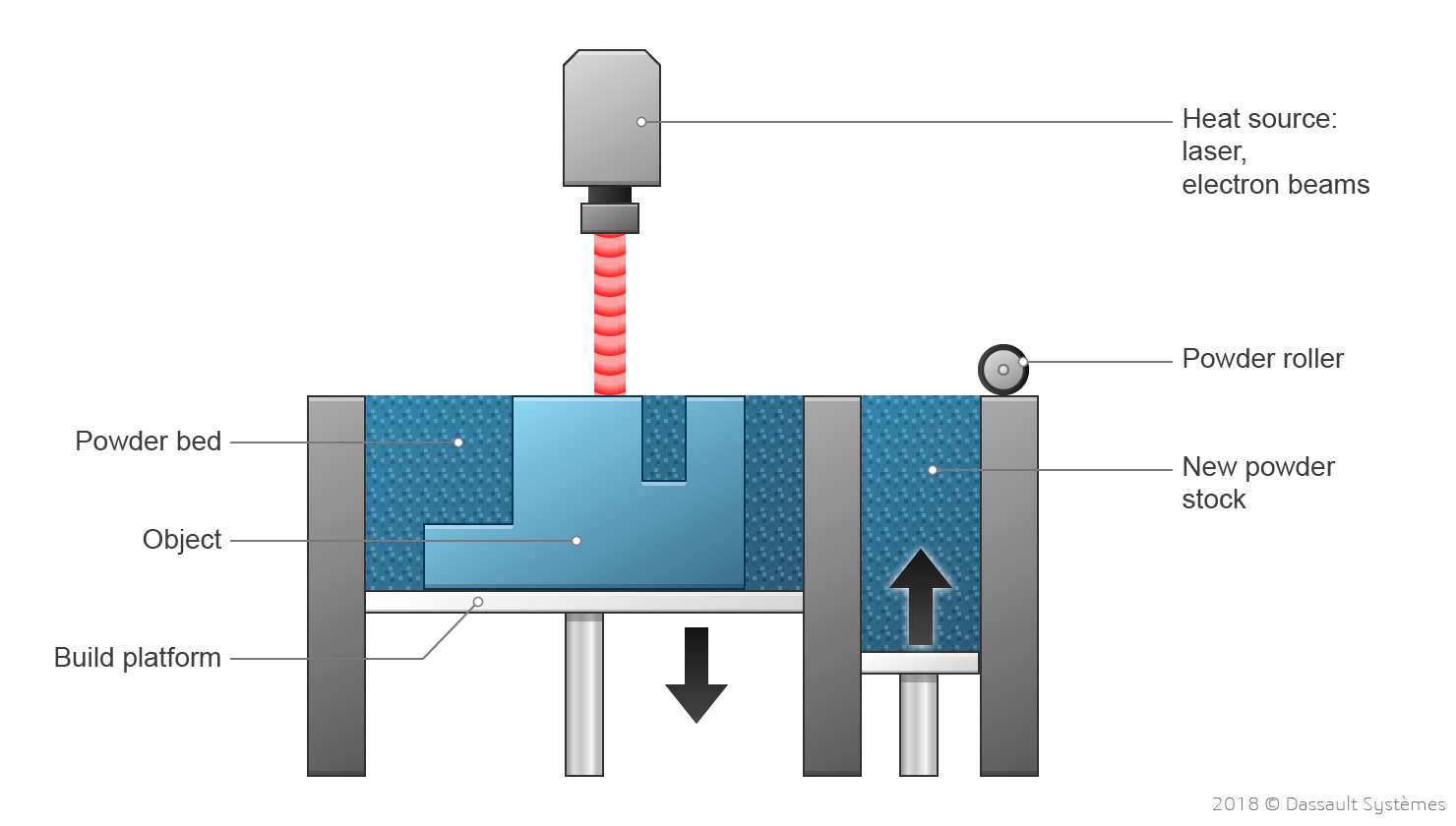
Powder Bed Fusion (PBF) 3D printing technology spawns products with precision. This 3D printing technique enables the manufacturing of a vast array of geometrically complex products using a heat source, mainly laser or electron beams, to fuse powder particles layer-by-layer, therefore forming a solid part. Manufacturers can benefit from substantial freedom of design considering that PBF presents several viable technologies and materials. The different Powder Bed Fusion methods notably include:
Selective Laser Sintering (SLS): SLS 3D printing technology originated in the late 1980s at the University of Texas at Austin. Over the years, this technology has experienced remarkable advances. Basically, the process uses lasers to sinter, or coalesce, powdered material layer-by-layer to create a solid structure. The final product, rendered enveloped in loose powder, is then cleaned with brushes and pressurized air. The main materials used in the SLS 3D printing process include polyamide (Nylons), Alumide (a blend of gray aluminum powder and polyamide), and rubber-like materials. Nylons are strong and durable but do feature some flexibility, making them excellent for snap fits, brackets, clips, and spring features. Designers should take the susceptibility for shrinkage and warping of thin parts into consideration during the conceptual phase. Please see the image below.

Selective Laser Melting (SLM): also called Direct Metal Laser Sintering (DMLS) The same technical principle is used to produce Selective Laser Melting (SLM) and Direct Metal Laser Sintering (DMLS) parts, but is exclusively used to produce metal parts. SLM achieves a full melt of the powder so that single-component metals, such as aluminum, can be used to create light, strong spare parts and prototypes. DMLS sinters the powders and is restricted to alloys, including titanium-based alloys. These methods require added support to compensate for the high residual stress and to limit the occurrence of distortion. Applications include jewelry and dental industries, spare parts, and prototypes. Please see the image above. Only difference is that it uses metal powder instead of powders of polyamide and alumide used in SLS.
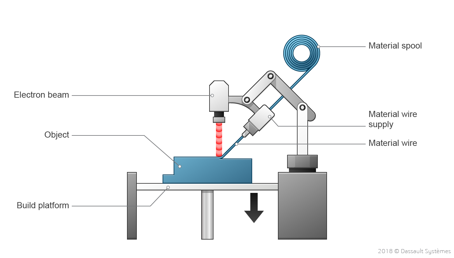
Electron Beam Melting (EBM): The EBM 3D printing technology attains fusion with the use of a high-energy electron beam and produces less residual stress resulting in less distortion. It uses less energy and can produce layers faster than SLS. This method is most useful in high-value industries such as aerospace and defense, motor sports, and medical prosthetics. Please see the image below.
 |
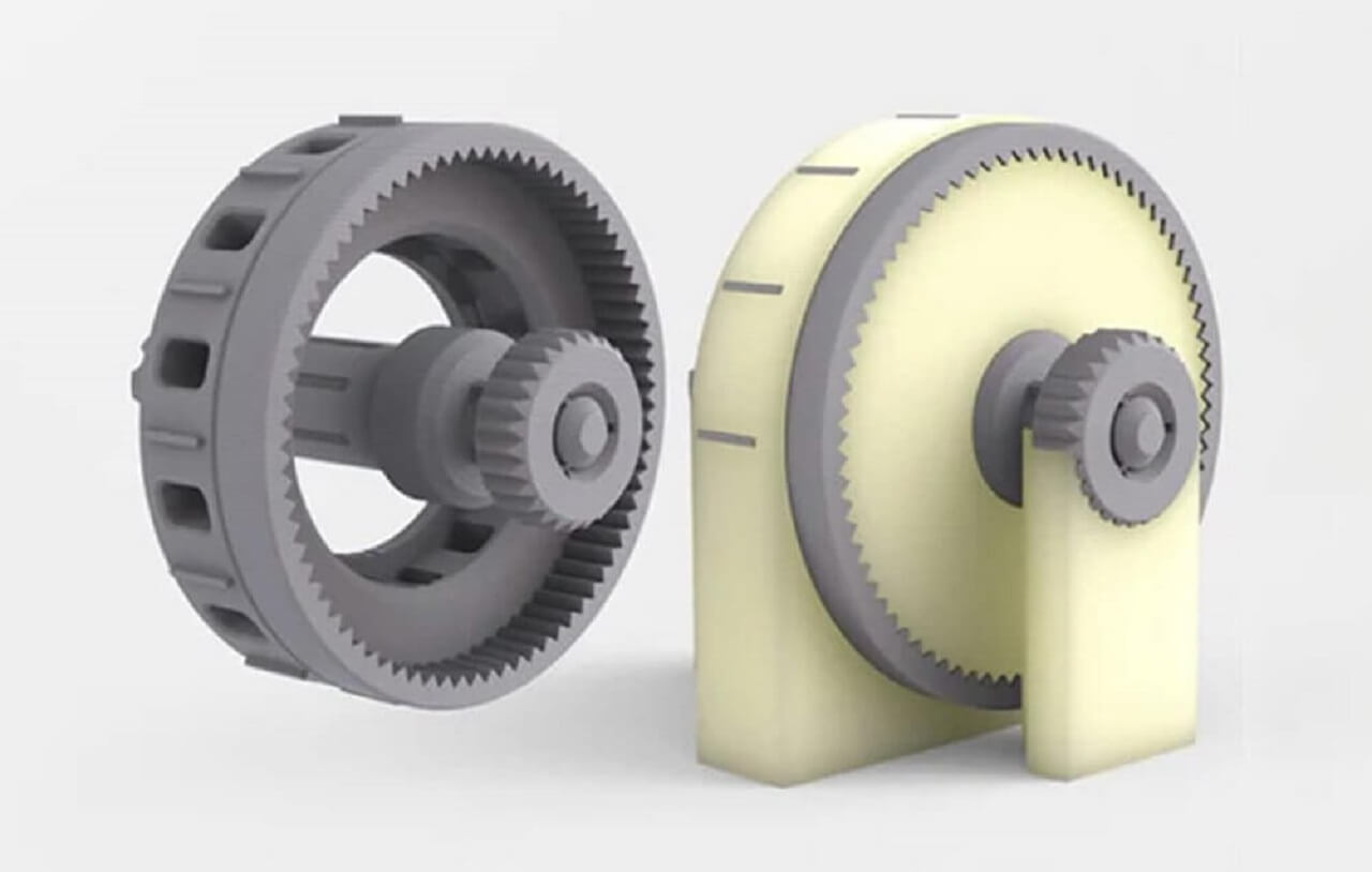
4. Material jetting - MJ, NPJ, DOD
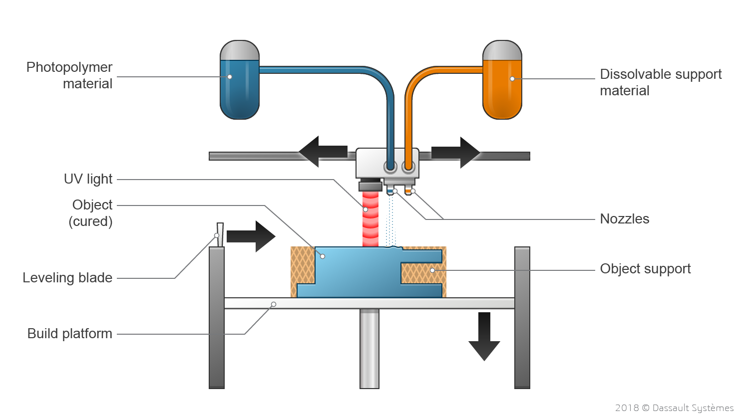
The Material Jetting 3D printing manufacturing technique is often compared to the standard 2D ink jetting process. Utilizing photopolymers, metals, or wax that solidify when exposed to light or heat (in a similar fashion to stereolithography) ensures that physical objects are built up one layer at a time. The material jetting manufacturing process allows for different materials to be 3D printed within the same part. Please see image below for all types of Material Jetting
Material jetting dispenses a photopolymer from hundreds of tiny nozzles in a printhead to build a part layer-by-layer. This allows material jetting operations to deposit build-material in a rapid, line-wise fashion, which can be compared to other point-wise deposition technologies that follow a path to complete the cross-sectional area of a layer, also called a slice. As the droplets are deposited to the build platform they are directly cured and solidified using UV light. Material jetting processes require support, which is often 3D printed simultaneously during the build from a dissolvable material. The support material is then removed during the post processing step. Several techniques make up the material jetting term, the most popular being:
Drop On Demand (DOD): DOD material jetting printers have two print jets: one to deposit the build material and another for dissolvable support material. Like all additive manufacturing machines, DOD 3D printers follow a pre-determined path and deposit material in a point-wise fashion to build the cross sectional area of a component. These machines also employ a fly-cutter that skims the build area after each layer to ensure a perfectly flat surface before printing the next layer. DOD technology is typically used to produce wax-like patterns for lost-wax casting/investment casting and mold making applications, making it an indirect 3D printing technique.
PolyJet by Objet: PolyJet 3D printing technology was first patented by the Objet company, now a Stratasys brand. The photopolymer materials are jetted in ultra-thin layers onto a build tray in a similar fashion compared to inkjet document printing. Each photopolymer layer is cured by UV light immediately after being jetted. The repetition of jetting and curing steps, layer after layer produces fully cured models that can be handled and used immediately. The gel-like support material, which is specially designed to support complex geometries, can easily be removed by hand or by using water jetting.
NanoParticle Jetting (NPJ) by XJet: This material jetting technology, patented by XJet, uses a liquid, which contains building nanoparticles or support nanoparticles, that is loaded into the printer as a cartridge and jetted onto the build tray in extremely thin layers of droplets. High temperatures inside the build envelope cause the liquid to evaporate leaving behind parts made from the building material. This technique is suitable for metals and ceramics.
 |
Advantages and Disadvantage of Material jetting
Material jetting 3D printing technology is a great choice for realistic prototypes, providing an excellent level of details, high accuracy and smooth surface finish. Material jetting allows a designer to print a design in multiple colors and with a number of materials in a single print. To designate a different material or color to particular areas of the part, the model must be exported as separate STL files. When blending colors or material properties to create a digital material, the design must be exported as an OBJ or VRML file, because these formats allow the designation of special properties (such as texture or full color) on a per-face or per-vertex basis.
The main drawbacks to printing with material jetting technologies are the high cost and the fact that UV activated photopolymers lose mechanical properties over time and can become brittle.Material jetting 3D printing technology is a grea
5. Binder Jetting
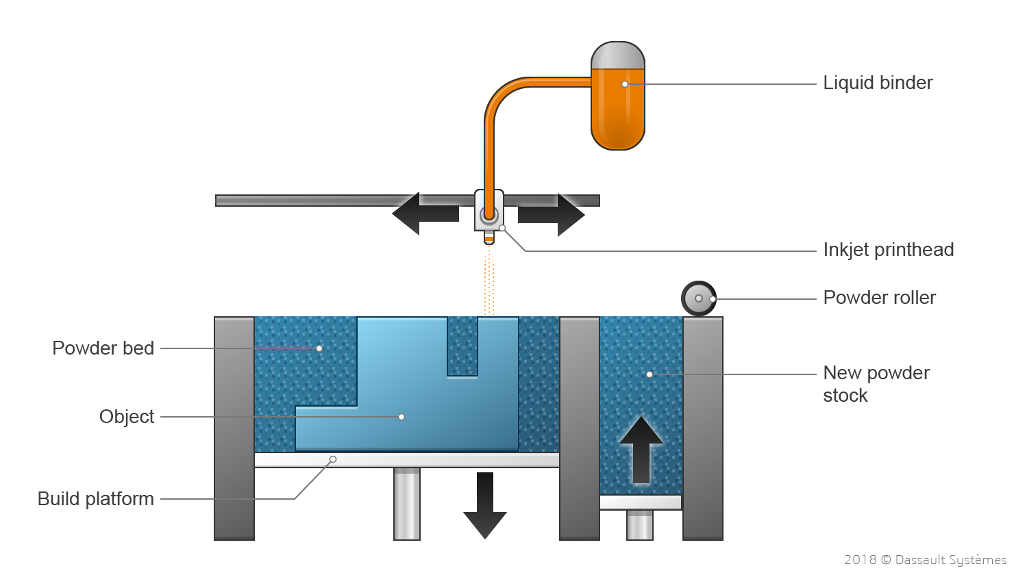
The binder jetting 3D printing technique consists of the deposition of a binding adhesive agent onto thin layers of powdered material. The powdered materials are either ceramic-based (for example glass or gypsum) or metal (for example stainless steel). Please see image below for all types of Binder Jetting
During the binder jetting 3D printing process, the 3D print head moves over the build platform depositing binder droplets, printing each layer in a similar fashion to 2D printers that print ink on paper. When a layer is complete, the powder bed moves downwards and a new layer of powder is spread onto the build area. The process is repeated layer by layer until all parts are complete. After printing, the parts are in a green, or unfinished, state and require additional post processing before they are ready to use. Often an infiltrant substance is added to improve the mechanical properties of the parts. The infiltrant substance is usually a cyanoacrylate adhesive (in case of ceramics) or bronze (in the case of metals). Another strategy is to put the workpiece, in its green state, inside an oven to achieve a sintering of the grains of matter. Interestingly, the term 3D printing originally referred to a process that deposited a binder material onto a powder bed with an inkjet printer-like heads layer by layer.
The binder jetting 3D printing process can work with a variety of materials including metals, sands, and ceramics. Some materials, like sand, require no additional processing.
There are various types of 3D printing binder materials, each suited for a specific application. They can be listed in categories including furan binder (for sand casting applications), phenolic binder (for sand molds and cores), silicate binder (environmentally-friendly, for sand molds and cores) and aqueous-based binder (for metals).
 |
 |
Advantages and Disadvantage of Binder Jetting
Binder jetting is great for applications that require good aesthetics and form, such as architectural models, packaging, toys and figurines. It is generally not suited for functional applications due to the brittle nature of the parts.
Compared to Powder Bed Fusion (PBF) 3D printing techniques, the binder jetting method has the advantage of not employing heat during the build process, which prevents the creation of residual stresses in the parts.
Metal-based binder jetting parts have relatively good mechanical properties and they can be used as functional components, thanks to the infiltration process. They are also more cost-effective than SLM (Selective Laser Melting) or DMLS (Direct Metal Laser Sintering) metal parts, but have poorer mechanical properties because the grains of materials do not entirely fuse together.
6. Directed energy deposition - DED, LENS, EBAM
The Directed Energy Deposition (DED) 3D printing technology, also known as Direct Energy Deposition, creates parts by directly melting materials and deposing them on the workpiece, layer by layer. This additive manufacturing technique is mostly used with metal powders or wire source materials. Other popular terms for DED include laser engineered net shaping, directed light fabrication, direct metal deposition, Laser Deposition Welding (LDW) and 3D laser cladding. In addition to the capability to build parts from scratch (often with the hybridation of a mill/turn CNC tool), DED is also capable of fixing complex damaged parts, such as turbine blades or propellers. Please see image below for all types of Binder Jetting
Most DED 3D printers are industrial machines with very large footprints that require a closed and controlled environment to operate. Therefore, typical Directed Energy Deposition consists of a nozzle mounted on a multi-axis arm inside a closed frame, which deposits melted material onto the workpiece surface, where it solidifies. The process is similar in principle to the material extrusion 3D printing technique, but with DED, a nozzle can move in multiple directions, with up to five different axes compared to only three for most FFF machines.
The Direct Energy Deposition term can encompass several different technologies. They distinguish themselves by the way the material is fused, each suited for different and specific purposes. The most popular are as follows:
LENS Technology by Optomec: LENS 3D manufacturing systems use lasers to build objects layer by layer directly from powdered metals, alloys, ceramics or composites. The LENS process must take place in a hermetically-sealed chamber which is filled with argon so that the oxygen and moisture levels stay very low. This keeps the part clean and prevents oxidation. The metal powder material is directly delivered to the material deposition head. Once a single layer has been deposited, the material deposition head moves on to the next layer. By building up successive layers, the whole part is constructed. When complete, the component is removed and can be heat-treated, hot isostatic pressed, machined, or finished in any required fashion.
Electron Beam Additive Manufacturing (EBAM): 3D Printing Technology by Sciaky. Electron Beam Additive Manufacturing (EBAM) is an additive manufacturing technology that produces large scale metal structures. The Sciaky companys proprietary Electron Beam (EB) gun deposits metal via a wire feedstock, layer by layer, until the part reaches near-net shape and is ready for finish machining. Material deposition rates range from 3 to 9 kg of metal per hour. Compatible metals include titanium, tantalum, and nickel. This DED technique can also be used to repair damaged parts.Please see the image below.
 |
Source and Credit for the literature: Dassault Systemes
3D Printing Materials
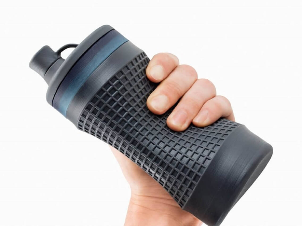
1. Plastic
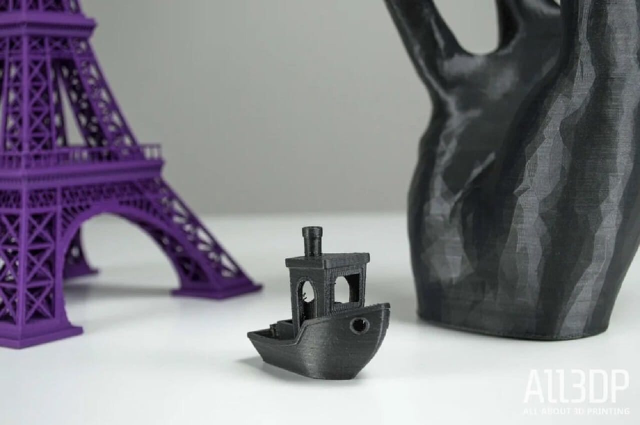
Out of all the raw materials for 3D printing in use today, plastic is the most common. Plastic is one of the most diverse materials for 3D-printed toys and household fixtures. Products made with this technique include desk utensils, vases and action figures. Available in transparent form as well as bright colors of which red and lime green are particularly popular. Plastic filaments are sold on spools and can have either a matte or shiny texture.
With its firmness, flexibility, smoothness and bright range of color options, the appeal of plastic is easy to understand. As a relatively affordable option, plastic is generally light on the pocketbooks of creators and consumers alike. Plastic products are generally made with FDM printers, in which thermoplastic filaments are melted and molded into shape, layer by layer. The types of plastic used in this process are usually made from one of the following materials:
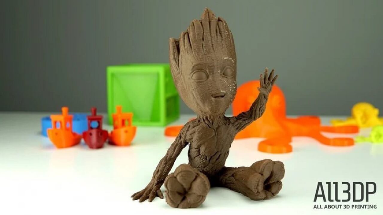
PLA- A crowd favorite in our 3D printing materials guide is Polyastic acid (PLA), which can, under certain commercially attainable conditions, biodegrade. PLA is sourced from natural products like sugar cane and corn starch and is therefore biodegradable. (You are not going to be able to compost it at home.)
First and foremost, PLA is easy to print with. It has a low printing temperature, does not need a heated bed (although it helps), and does not warp as easily. Another benefit of using PLA is that it does not give off an offputting odor during printing (unlike ABS). Moreover, it is a suitable 3D printing material for single-use food contact. However, PLA is less durable than ABS or PETG and susceptible to heat. So, for any type of engineering part, you will be better off with the latter. Avoid using it when making items that might be bent, twisted, or repeatedly dropped, such as phone cases, high-wear toys, or tool handles. PLA is available in a broad range of colors and also comes in a variety of composites from glow-in-the-dark, glittery, or color changing.
 |
ABS- Remember the quality of Lego bricks? Then you can relate to why Acrylonitrile butadiene styrene (ABS) is one of the most popular 3D printing materials to date. Made from petroleum, ABS is commonly used in injection molding and is found in many household items, such as those rock-hard Lego bricks, phone cases, or bicycle helmets due to its durability, robustness, and temperature resistance.
While it plays a major role in commercial applications such as rapid prototyping, in hobbyist 3D printing, ABS is less popular. This is due to it being slightly more difficult to print, it is prone to warping without an enclosed and heated build chamber. Nonetheless, ABS makes a good general-purpose 3D printer filament for DIY projects. It is available in various colors that make the material suitable for products like high-wear toys, stickers, tool handles, automotive trim components, and electrical enclosures. Increasingly popular among craftspeople, ABC is also used to make jewellery and vases. It is readily affordable, strong, lightweight, allows for easy post-processing, and comes in a broad range of colors. However, ABS releases smelly and toxic chemicals during printing. Address this by printing in a well-ventilated area and/or with an enclosure.
 |
PETG- PETG is made from Polyethylene Terephthalate (PET), the material you know from plastic water bottles, but some ethylene glycol is replaced with CHDM (cyclohexanedimethanol), hence the letter 'G' after PET for 'glycol-modified'. The result is a filament that is clearer, less brittle, and easier to use than its base form of PET.
Its an excellent filament choice for printing objects that need to be sturdy, have a smooth surface, and have lower shrinkage. PETG components are weather-resistant and are thus often used for garden appliances. It is also popular because PETG is considered food-safe but you should still read the fine print on any spool you buy to be sure. Of course, it is not all good news: PETG is not great at bridging because it is super sticky, but this does mean it has great layer adhesion. It is also more hygroscopic than PLA, so it can be prone to both heavy stringing and air-moisture absorption if left out. But still, if you need a good all-around, high-strength material that is less complicated to print than ABS, PETG is a great option.
 |
PVA- Polyvinyl alcohol (PVA) is soluble in water, and that is exactly what commercial applications take advantage of. Popular uses include packaging for dishwasher detergent 'pods' or bags full of fishing bait. (Throw the bag in water and watch it dissolve, releasing the bait.)
Used in low-end home printers, PVA is a suitable plastic for support materials of the dissolvable variety. Though not suitable for products that require high strength, PVA can be a low-cost option for temporary-use items. For 3D printing, PVA, like HIPS, is engineered for use as a soluble support material, primarily when paired with another 3D printer filament in a dual extrusion 3D printer. The advantage of using PVA over HIPS is that it can support more materials than just ABS. The trade-off is a 3D printer filament that is slightly more difficult to handle. One must also be careful when storing it, as the moisture in the atmosphere can damage the filament before printing. Dry boxes and silica pouches are a must if you plan to keep a spool of PVA usable in the long run.
 |
Nylon- Nylon, a branch of synthetic polymers, is a tough and durable material originally seen in textiles. The technical name for the material is polyamide (PA), while the common name is 'nylon' (despite some still associating it with stockings). The material stands out for its toughness and its resistance to high temperatures and impacts. It also has a very low coefficient of friction, making it the ideal 3D printing material for parts that require good tensile and mechanical strength.
Furthermore, Nylon prints have a rough surface that can be polished smooth. Plus, given its flexibility and strength, nylon is the premier choice for various applications from engineering to the arts. While you should not expect it to print as easily as PLA or PETG, printability should not be a deal-breaker, but you may need a high-temperature nozzle, as some blends will need up to 300 deg C to be processed.
 |
HIPS- High impact polystyrene (HIPS) is a material blend of polystyrene plastic and polybutadiene rubber. The mixture of these polymers results in a material that is both tough and flexible. HIPS is very similar to ABS, but as the name implies, it can withstand much higher impact forces. It is easily painted, machinable, and works with a large number of adhesives. Moreover, it is food-safe, being declared FDA-compliant for food processing applications.
Within the 3D printing world, HIPS is mostly used as support material since it dissolves in limonene solution, eliminating the need for removal via abrasives, cutting tools, or any other such things that leave your print less than perfect. Limonene is a solution made with lemon peels, and it can be easily obtained. This solution, however, can potentially damage 3D printing materials other than ABS.
 |
2. Powders
Todays more state-of-the-art 3D printers use powdered materials to construct products. Inside the printer, the powder is melted and distributed in layers until the desired thickness, texture and patterns are made. The powders can come from various sources and materials, but the most common are:
Polyamide (Nylon)- With its strength and flexibility, polyamide allows for high levels of detail on a 3D-printed product. The material is especially suited for joining pieces and interlocking parts in a 3D-printed model. Polyamide is used to print everything from fasteners and handles to toy cars and figures.
Alumide- Comprised of a mix of polyamide and gray aluminum, alumide powder makes for some of the strongest 3D-printed models. Recognized by its grainy and sandy appearance, the powder is reliable for industrial models and prototypes.
In powder form, materials like steel, copper and other types of metal are easier to transport and mold into desired shapes. As with the various types of plastic used in 3D printing, metal powder must be heated to the point where it can be distributed layer-by-layer to form a completed shape.
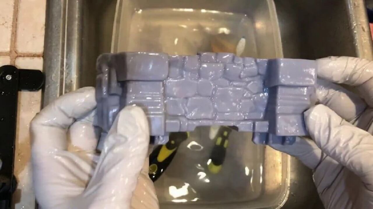
3. Resins
Resins (photopolymers) are a range of 3D printable liquids that solidify when exposed to ultraviolet (UV) light. They are used in a process broadly known as vat polymerization, which has many variants, including stereolithography (SLA), digital light processing (DLP), and masked stereolithography (MSLA). These essentially all work in the same way: by using the selective application of UV light to trace the shape of an object onto the surface of a photopolymer vat; the resin solidifies to form a layer of the object, which is repeated for every layer of the model until a 'green' state model is left. Resin is generally found in black, white and transparent varieties, but certain printed items have also been produced in orange, red, blue and green.
One of the more limiting and therefore less-used materials in 3D printing is resin. Compared to other 3D-applicable materials, resin offers limited flexibility and strength.
The material comes in the following categories:
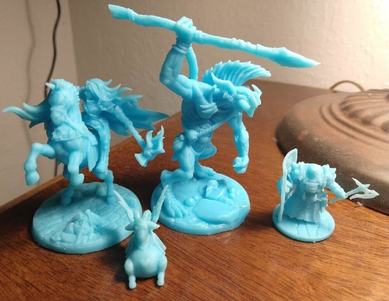
High-detail resins- Generally used for small models that require intricate detail. For example, four-inch figurines with complex wardrobe and facial details are often printed with this grade of resin.
Paintable resin- Sometimes used in smooth-surface 3D prints, resins in this class are noted for their aesthetic appeal. Figurines with rendered facial details, such as fairies, are often made of paintable resin.
Transparent resin- This is the strongest class of resin and therefore the most suitable for a range of 3D-printed products. Often used for models that must be smother to the touch and transparent in appearance.
Standard Resins- If you are using an SLA, DLP, or MSLA printer, you are going to need some resin. Resin can feature all kinds of different properties, but if you are looking for something straightforward, standard resin is the way to go. It is perfect for applications like creating conceptual models, functional models, prototypes, miniatures, and visual arts. Standard resins come in a range of colors and, like all other resins, can be pretty stinky, so be sure to use them in well-ventilated areas.
 |
Rapid Resin- Resin that cures quickly has multiple benefits beyond a quick turnaround. The shortened time frame prevents shrinking and deformation of parts still soft from the bath. Use this resin if precision is needed, such as when making tools or components, and if waiting is not your strong suit.
 |
Tough Resins- Marketed under many different names, ABS-like tough-resins boast a high level of impact resistance. Acrylonitrile butadiene styrene (ABS) is a plastic commonly used in toy manufacturing, personal protective equipment such as hard hats and helmets, and other uses where the object will be put through stress.Tough resin is ideal for conceptual models, functional parts, and prototypes.
 |
Water-Washable Resins- Water washable resins take away a lot of the mess and stink-factor of standard resins because, well, they are water washable. That means that instead of using alcohol to clean your parts, you use water. This is a safer, cleaner alternative to use if you are new to resins, are looking for something that is easier to work with, hate the smells from printing with resin, or would just like to save some money.
 |
Flexible Resins- Sometimes, you need to be a little flexible. FDM printers use thermoplastic polyurethane (TPU), a rubber-like material found on drop-proof mobile phone cases. But if you are in the market for a TPU-like resin, it often goes under the line name 'Flex' and can be similarly used for items where high elasticity and vibration absorption are needed, such as racecar wheels.
 |
Plant-Based Resin- Using soybeans and similar plants as the setting agents for the resin, rather than traditional sources, plant-based resins make some small steps towards making resin 3D printing less toxic and messy. Be sure to check out the material safety data sheet for any plant-based resin you buy. Do not always assume you can wash it or toss it out in the trash.
 |
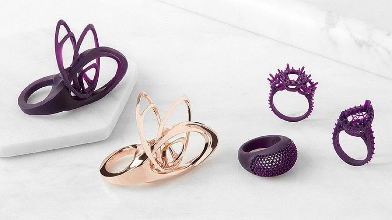
Castable Resins- A major advantage of 3D printing is its ease and speed in prototyping, and castable resin and the lost wax method is a prime example of that. A wax model is encased in a plaster-like medium that hardens and is then heated, so the wax model melts away, leaving a mold that is then filled with liquid precious metal. This way, jewelers can print a model, use it to form a cement mold and burn away the resin in a furnace, allowing the liquid metal to be poured into its place. A single 3D printed ring or brooch in this castable resin can form the mold for dozens in gold, silver, or other metals. Castable resin 3D makes it possible to create a finely detailed master wax model.
 |
4. Metal
The second-most-popular material in the industry of 3D printing is metal, which is used through a process known as direct metal laser sintering or DMLS. This technique has already been embraced by manufacturers of air-travel equipment who have used metal 3D printing to speed up and simplify the construction of component parts.
DMLS printers have also caught on with makers of jewelry products, which can be produced much faster and in larger quantities, all without the long hours of painstakingly detailed work with 3D printing. Metal can produce a stronger and arguably more diverse array of everyday items. Jewelers have used steel and copper to produce engraved bracelets on 3D printers. The range of metals that are applicable to the DMLS technique is just as diverse as the various 3D printer plastic types:
Stainless-steel: Ideal for printing out utensils, cookware and other items that could ultimately come into contact with water.
Bronze: Can be used to make vases and other fixtures.
Gold: Ideal for printed rings, earrings, bracelets and necklaces.
Nickel: Suitable for the printing of coins.
Aluminum: Ideal for thin metal objects.
Titanium: The preferred choice for strong, solid fixtures.
5. Metal Composite
Since this is a consumer materials guide, the 'metal' filament you will be able to use at home is actually a thermoplastic, typically PLA, that is been mixed with low amounts of metal particles to give your 3D printed model the optical properties of metal. Even the weight is metal-like, as blends tend to be several times denser than pure plastic filament. It will not have the actual functionality of metal, though.
Metal composite prints can be highly aesthetic, especially for figurines, models, toys, and tokens. It�s great for post-processing, including sanding, polishing, weathering, or tarnishing.
 |
6. Wood Composite
Wood 3D printer filament is typically a PLA infused with wood fiber. There are many wood-PLA 3D printer filaments available today. These include the more standard wood varieties, such as pine, birch, cedar, ebony, and willow, but the range also extends to less common types, like bamboo, cherry, coconut, cork, and olive.
As with other types of 3D printer filament, there is a trade-off with using wood. In this case, the aesthetic and tactile appeal come at the cost of reduced flexibility and strength. Wood-filled filament can also accelerate the degradation of your 3D printers nozzle, so keep that in mind before using this material.
Be careful with the temperature at which you print wood, as too much heat can result in an almost burnt or caramelized appearance. On the other hand, the base appearance of your wooden creations can be greatly improved with a little post-print processing! You can cut it, sand it, or paint it.
 |
7. Carbon Fiber
Composites such as carbon fiber are used in 3D printers as a top-coat over plastic materials. The purpose is to make the plastic stronger. The combination of carbon fiber over plastic has been used in the 3D printing industry as a fast, convenient alternative to metal. In the future, 3D carbon fiber printing is expected to replace the much slower process of carbon-fiber layup.
With the use of conductive carbomorph, manufacturers can reduce the number of steps required to assemble electromechanical devices.
8. Graphite and Graphene
Graphene has become a popular choice for 3D printing because of its strength and conductivity. The material is ideal for device parts that need to be flexible, such as touchscreens. Graphene is also used for solar panels and building parts. Proponents of the graphene option claim it is one of the most flexible of 3D-applicable materials.
The use of graphene in printing received its largest boost through a partnership between the 3D Group and Kibaran Resources, an Australian mining company. The pure carbon, which was first discovered in 2004, has proven to be the most electrically conductive material in laboratory tests. Graphene is light yet strong, which makes it the suitable material for a range of products.
9. Nitinol
As a common material in medical implants, nitinol is valued in the 3D printing world for its super-elasticity. Made from a mixture of nickel and titanium, nitinol can bend to considerable degrees without breaking. Even if folded in half, the material can be restored to its original shape. As such, nitinol is one of the strongest materials with flexible qualities. For the production of medical products, nitinol allows printers to accomplish things that would otherwise be impossible.
10. Paper
Designs can be printed on paper with 3D technology to achieve a far more realistic prototype than a flat illustration. When a design is presented for approval, the 3D-printed model allows the presenter to convey the essence of the design with greater detail and accuracy. This makes the presentation far more compelling, as it gives a more vivid sense of the engineering realities should the design be taken to fruition.
Source and Credit for the 3D printing materials: ALL3DP
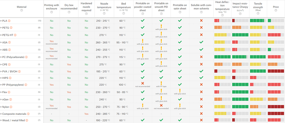
Material Properties
Below is one filament guide table that includes all sorts of supported filament, divided both by material and specific manufacturers. Here, one can compare their parameters including physical properties of the filament. Click here to know more.
One more source to refer: For materials and their properties.
 |
Click here to go back to the top
3D Scanning
3D scanning is the process of analyzing a real-world object or environment to collect data on its shape and possibly its appearance (e.g. colour). The collected data can then be used to construct digital 3D models.
A 3D scanner can be based on many different technologies, each with its own limitations, advantages and costs. Many limitations in the kind of objects that can be digitised are still present. For example, optical technology may encounter many difficulties with dark, shiny, reflective or transparent objects. For example, industrial computed tomography scanning, structured-light 3D scanners, LiDAR and Time Of Flight 3D Scanners can be used to construct digital 3D models, without destructive testing.
Collected 3D data is useful for a wide variety of applications. These devices are used extensively by the entertainment industry in the production of movies and video games, including virtual reality. Other common applications of this technology include augmented reality, motion capture, gesture recognition, robotic mapping, industrial design, orthotics and prosthetics, reverse engineering and prototyping, quality control/inspection and the digitization of cultural artifacts.
Functionality: The purpose of a 3D scanner is usually to create a 3D model. This 3D model consists of a polygon mesh or point cloud of geometric samples on the surface of the subject. These points can then be used to extrapolate the shape of the subject (a process called reconstruction). If colour information is collected at each point, then the colours or textures on the surface of the subject can also be determined. 3D scanners share several traits with cameras. Like most cameras, they have a cone-like field of view, and like cameras, they can only collect information about surfaces that are not obscured. While a camera collects colour information about surfaces within its field of view, a 3D scanner collects distance information about surfaces within its field of view. The "picture" produced by a 3D scanner describes the distance to a surface at each point in the picture. This allows the three dimensional position of each point in the picture to be identified.
In some situations, a single scan will not produce a complete model of the subject. Multiple scans, from different directions are usually helpful to obtain information about all sides of the subject. These scans have to be brought into a common reference system, a process that is usually called alignment or registration, and then merged to create a complete 3D model. This whole process, going from the single range map to the whole model, is usually known as the 3D scanning pipeline. Click here to read more.
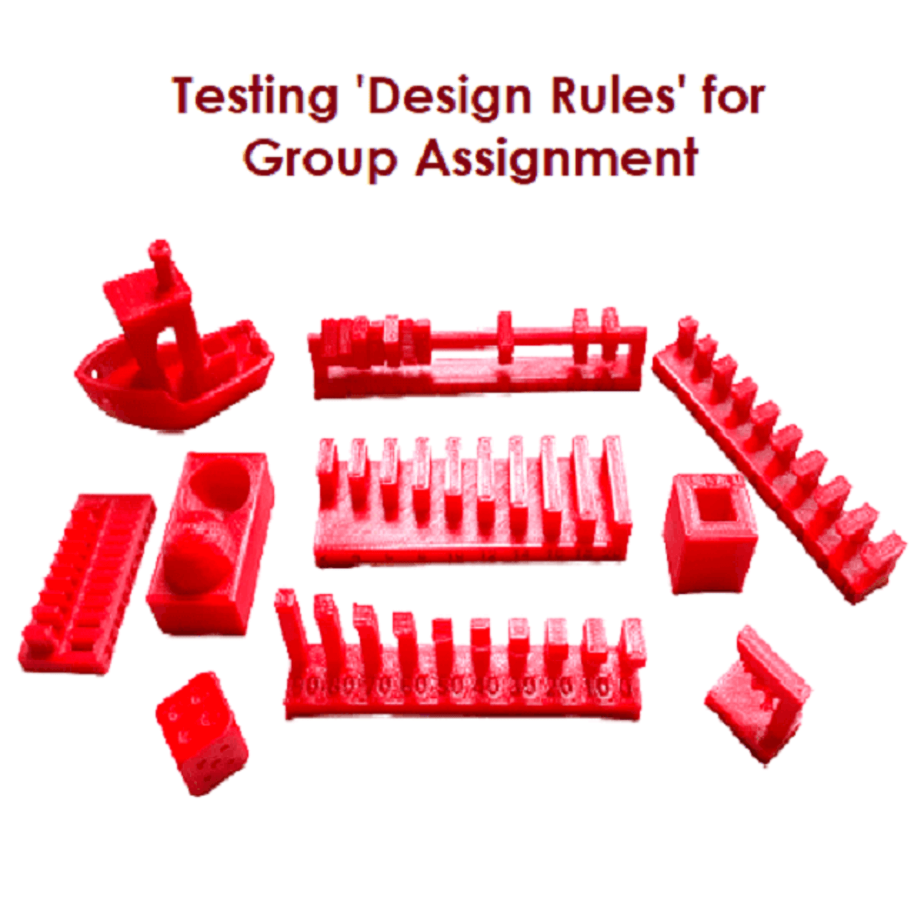
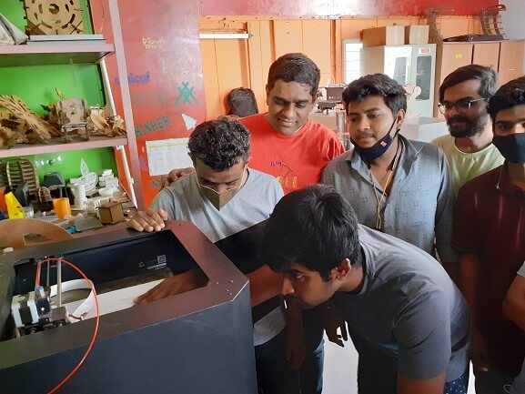
Group Assignment Brief
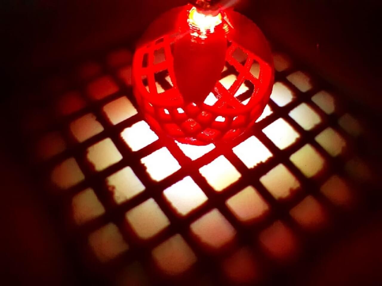
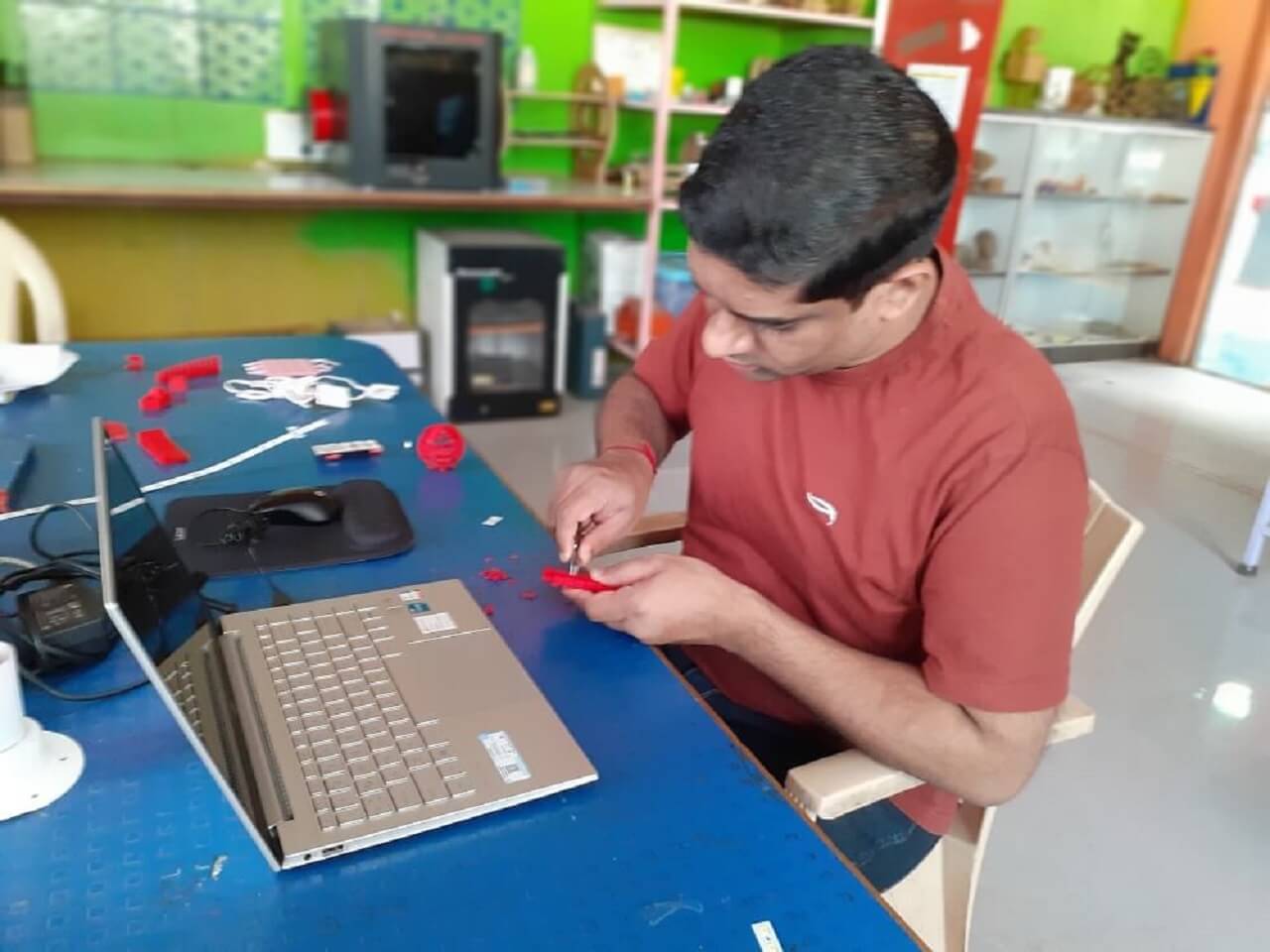
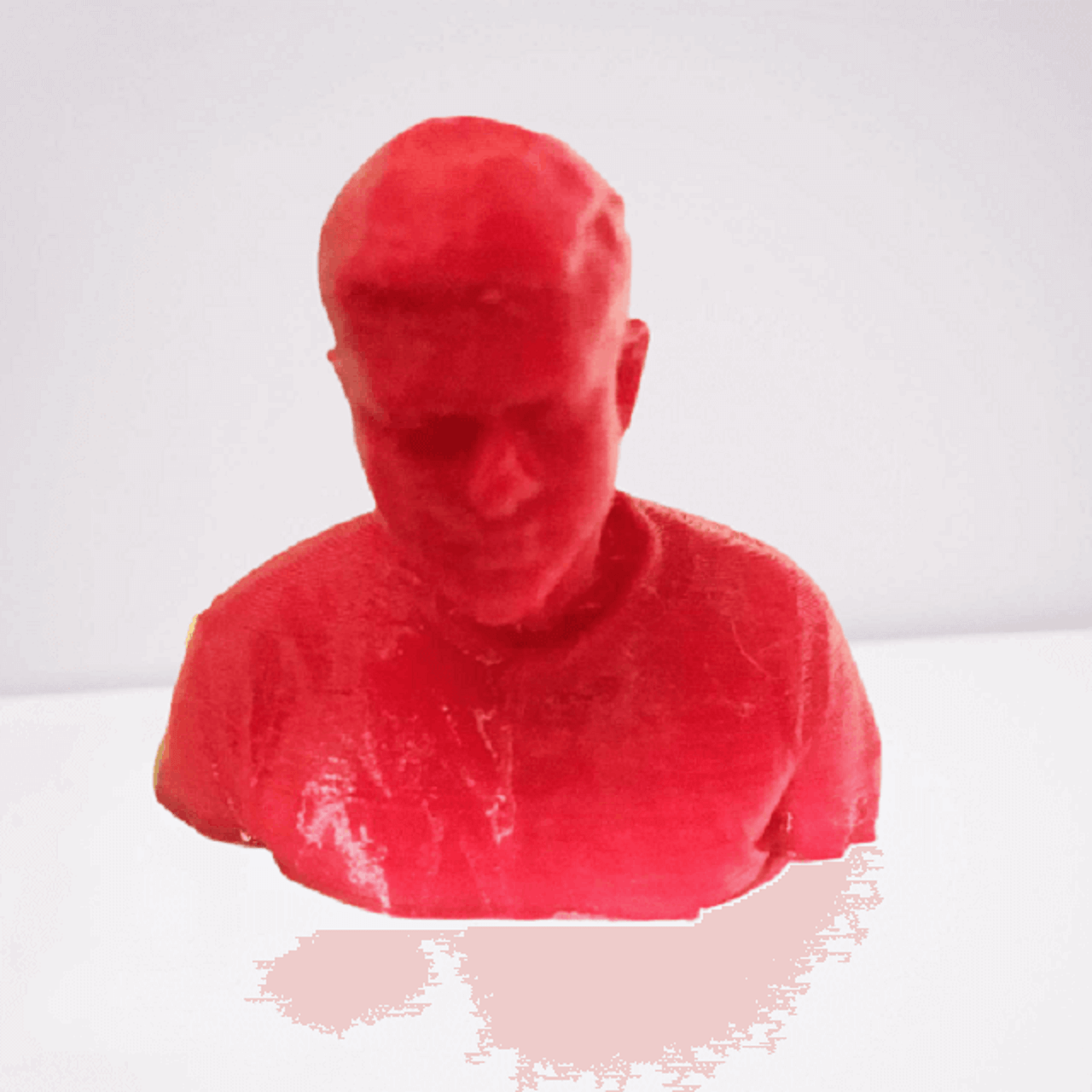
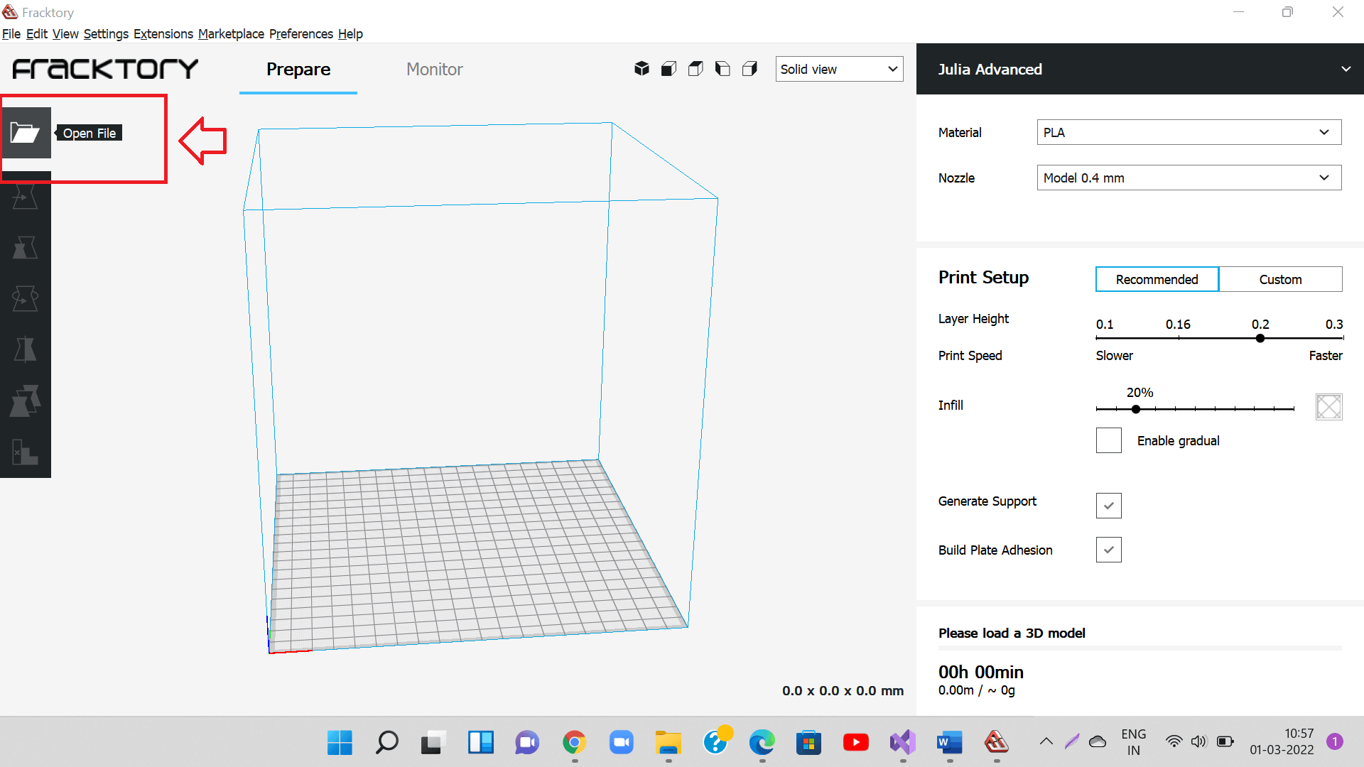
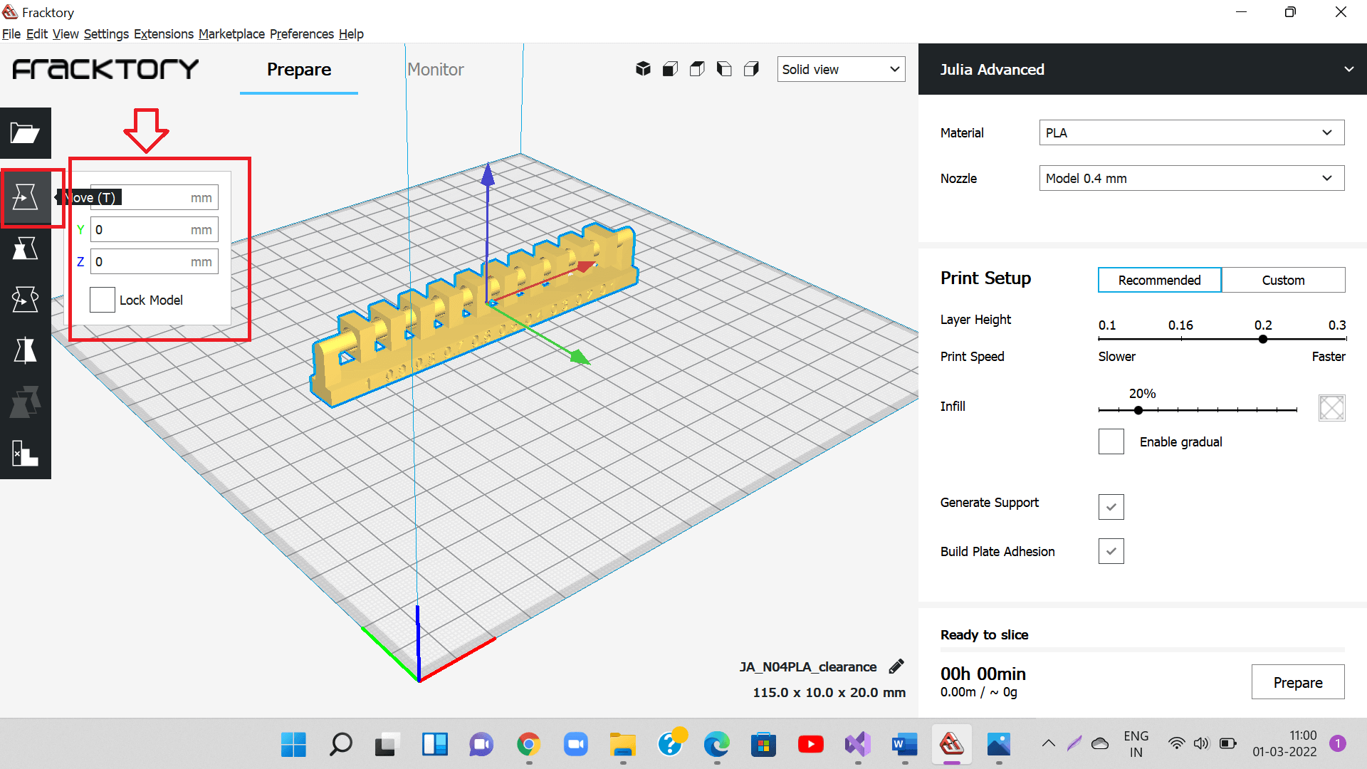
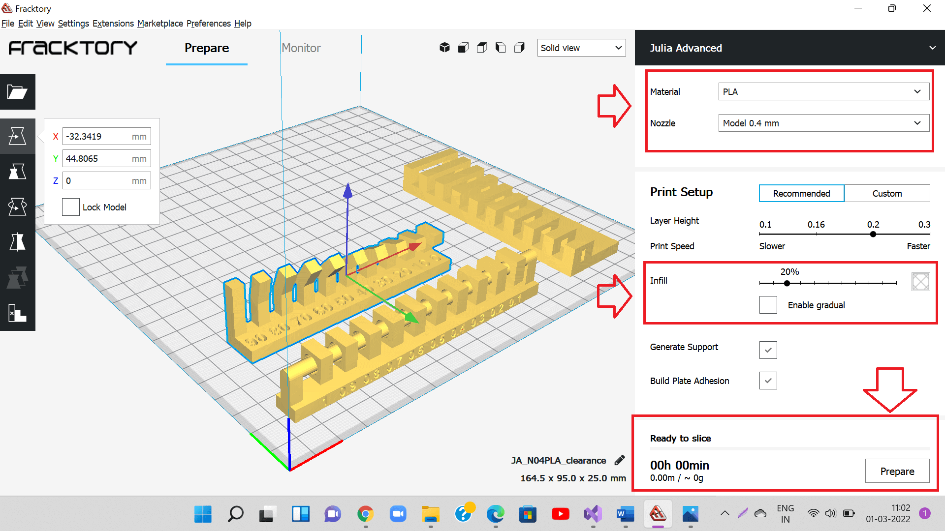
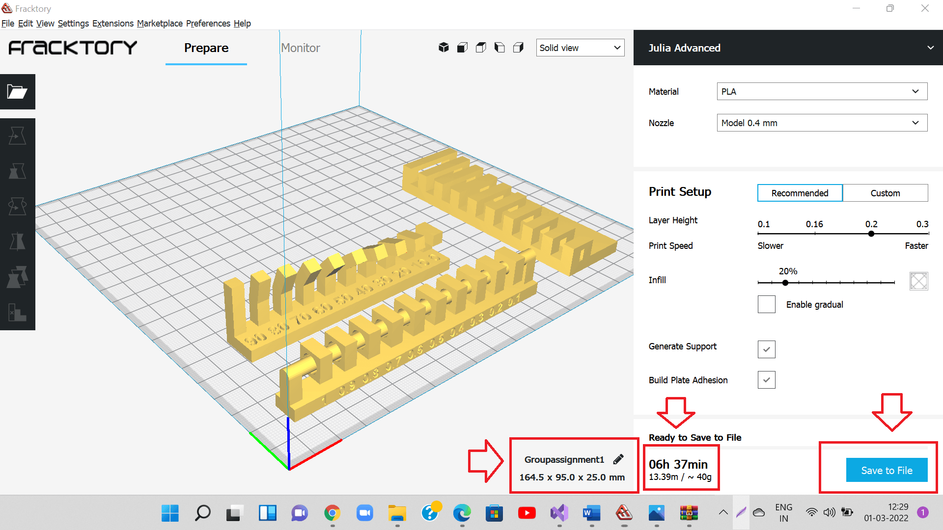
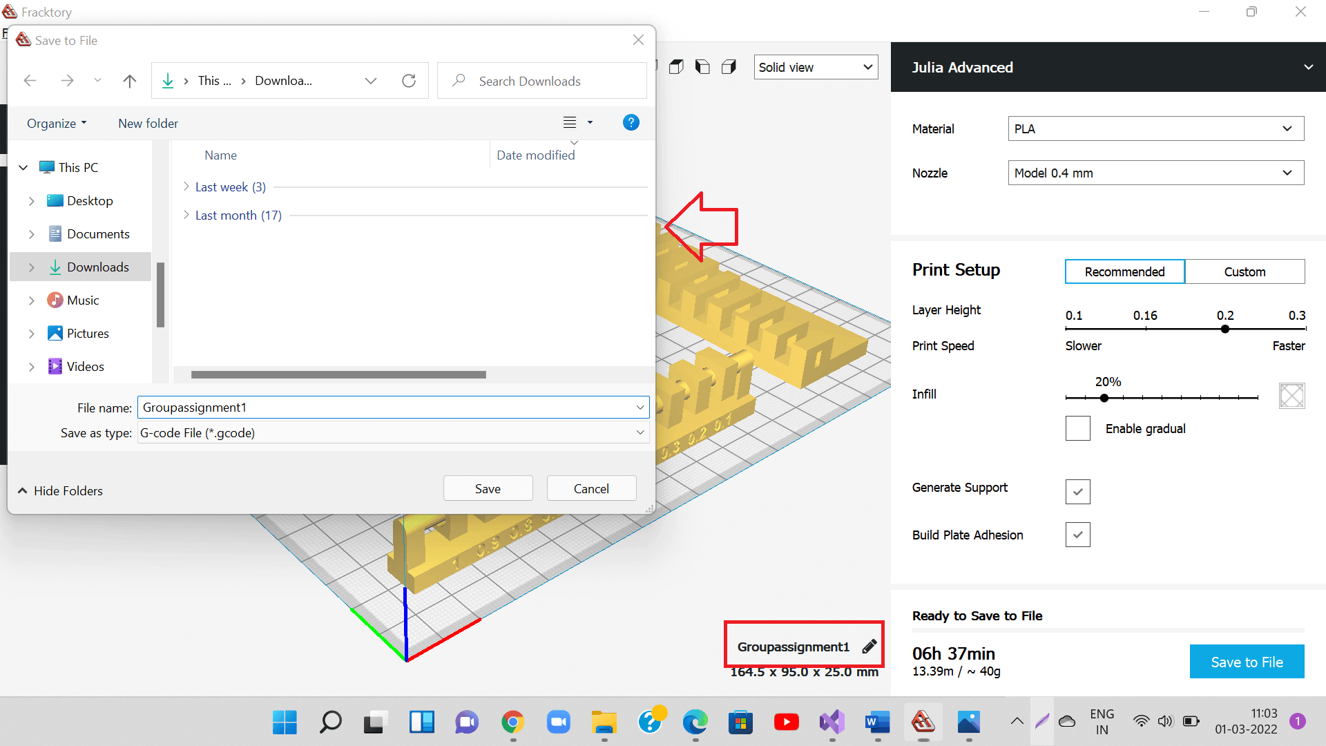
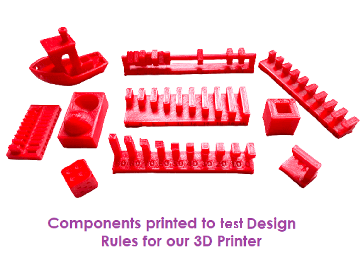
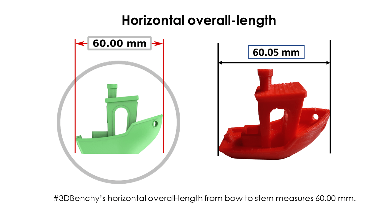
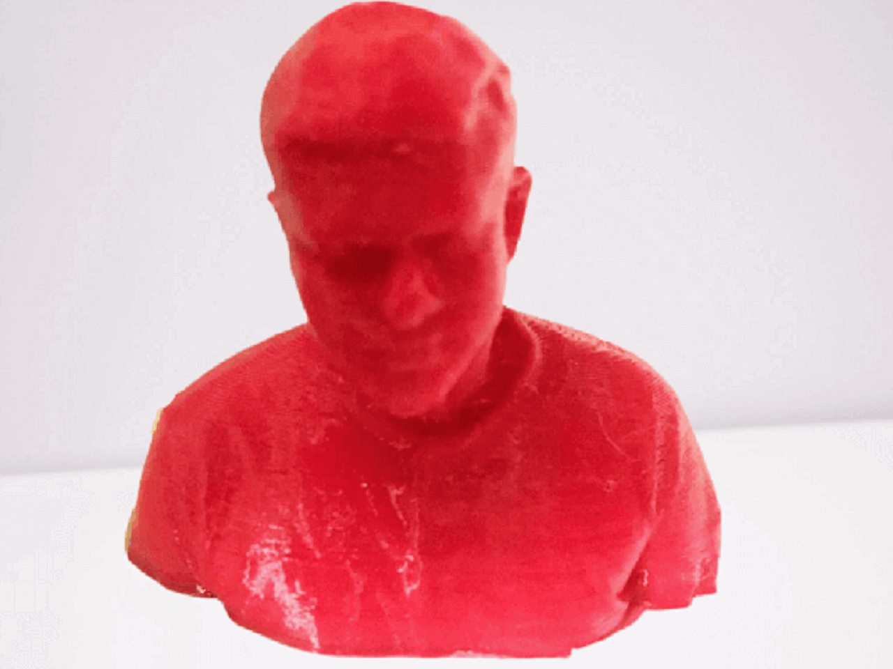
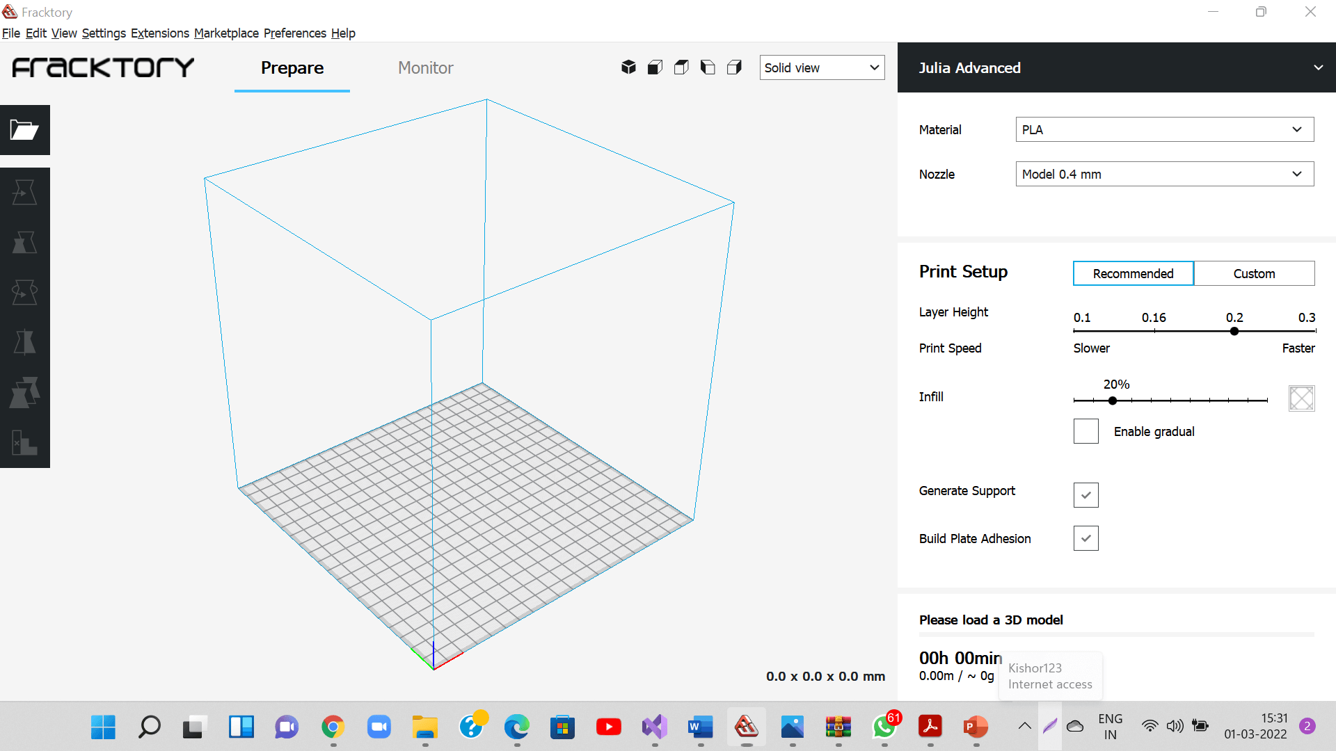
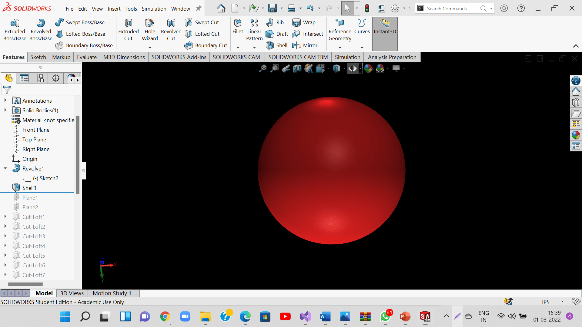
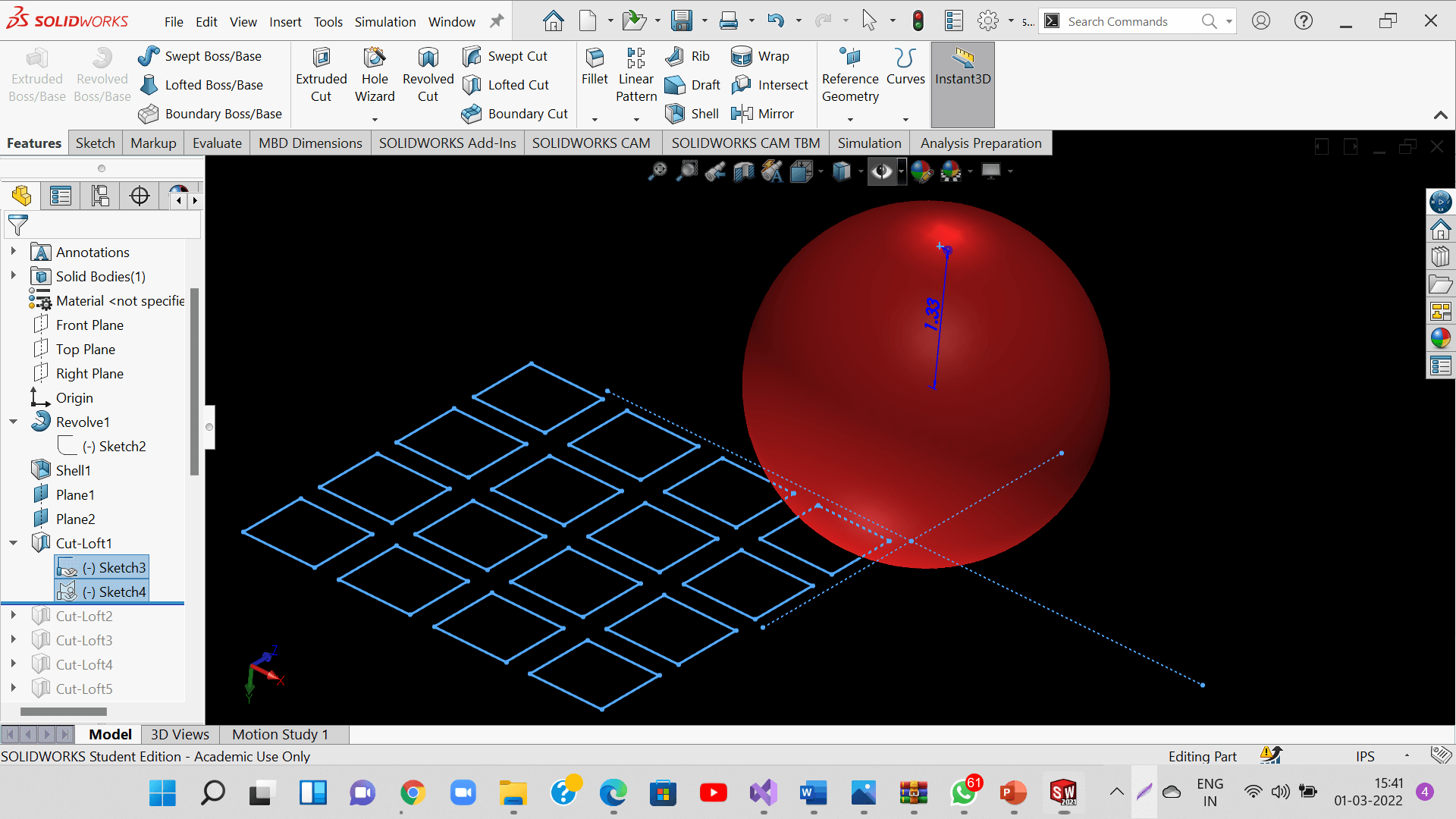
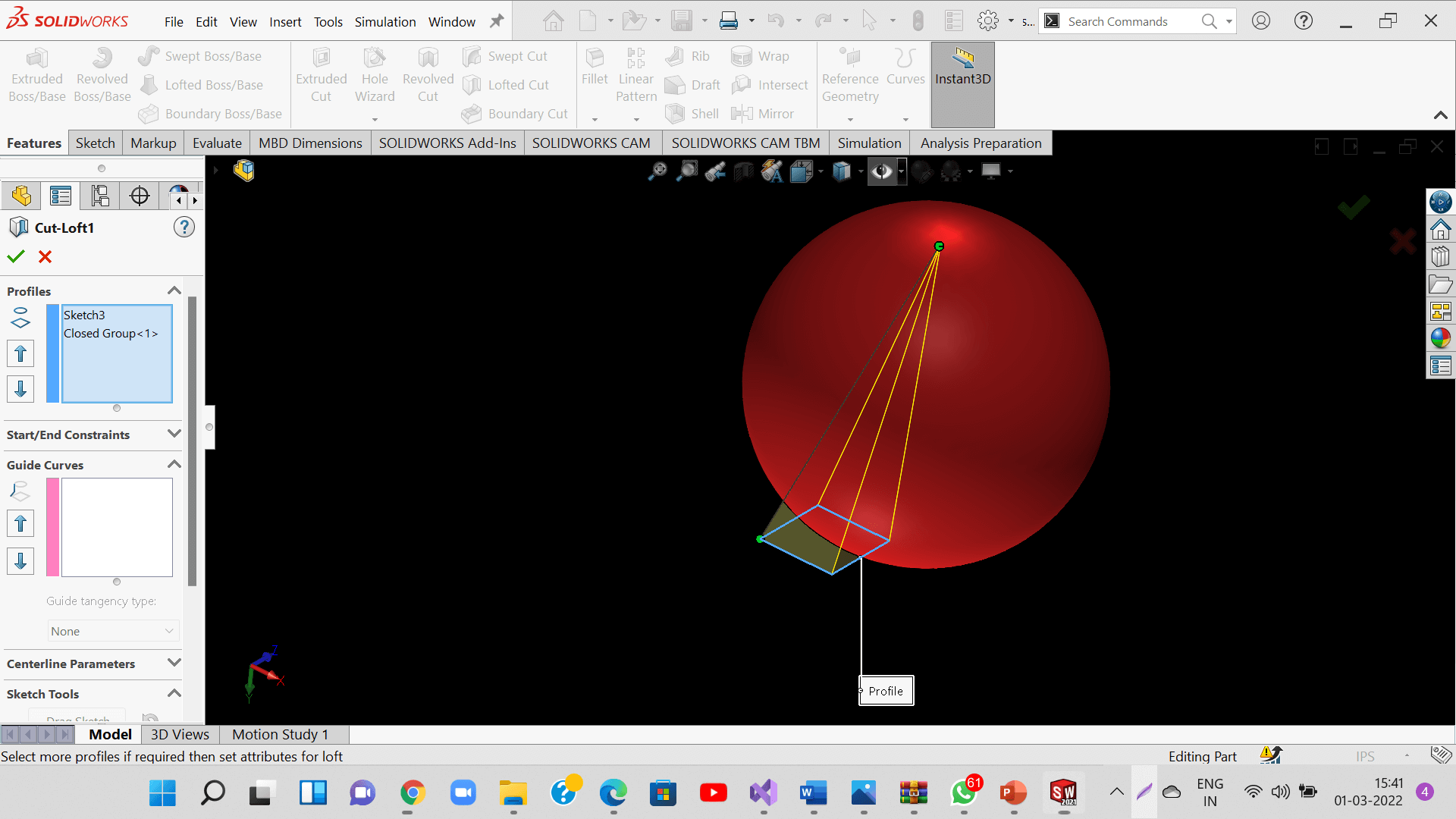
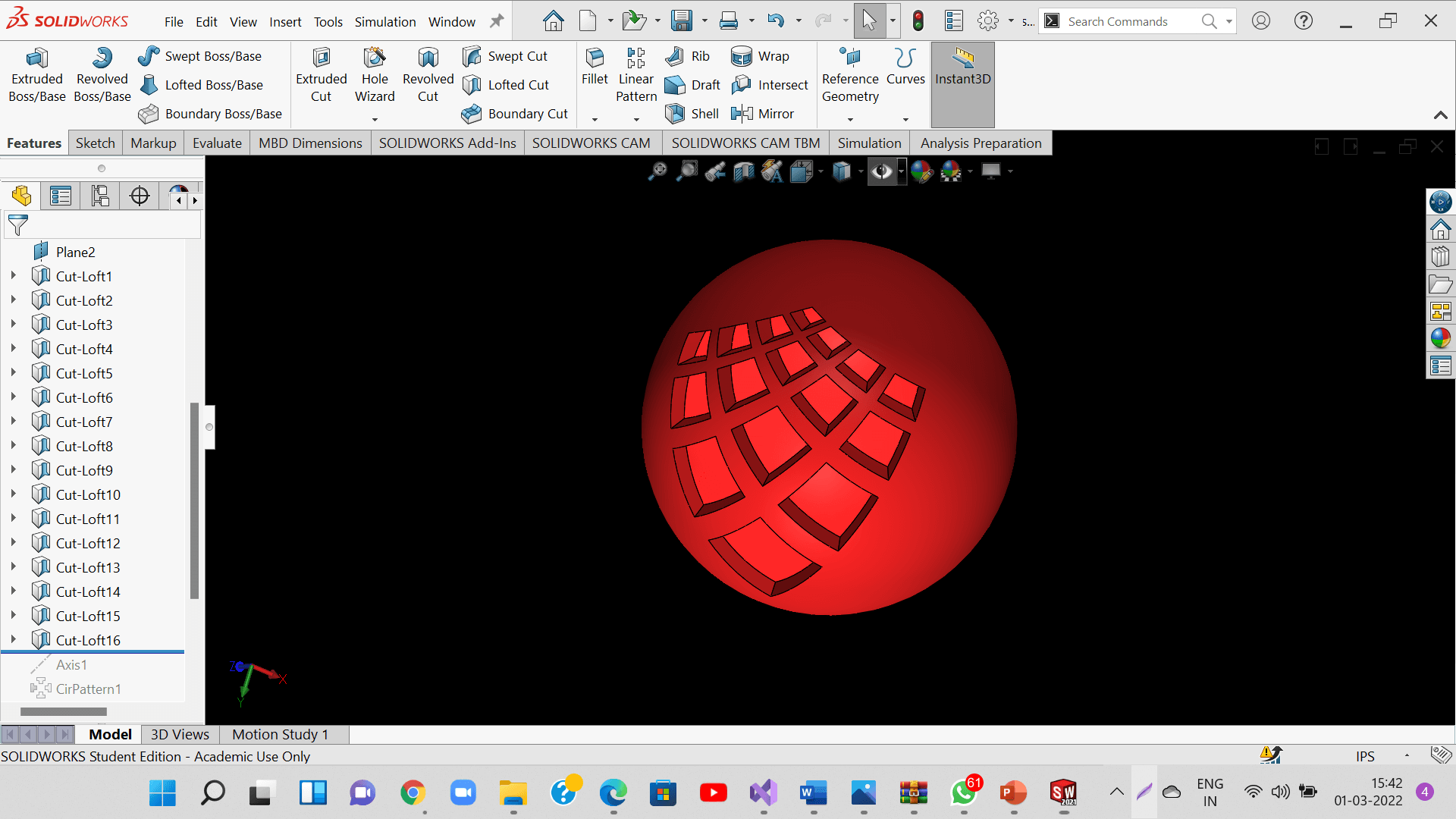
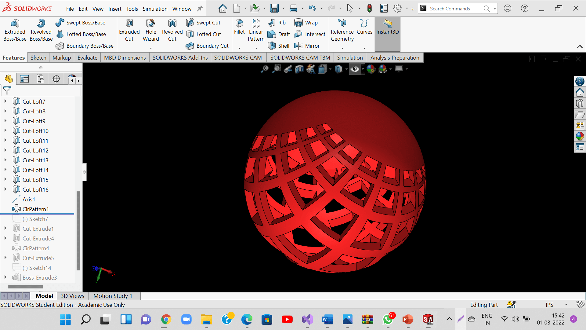
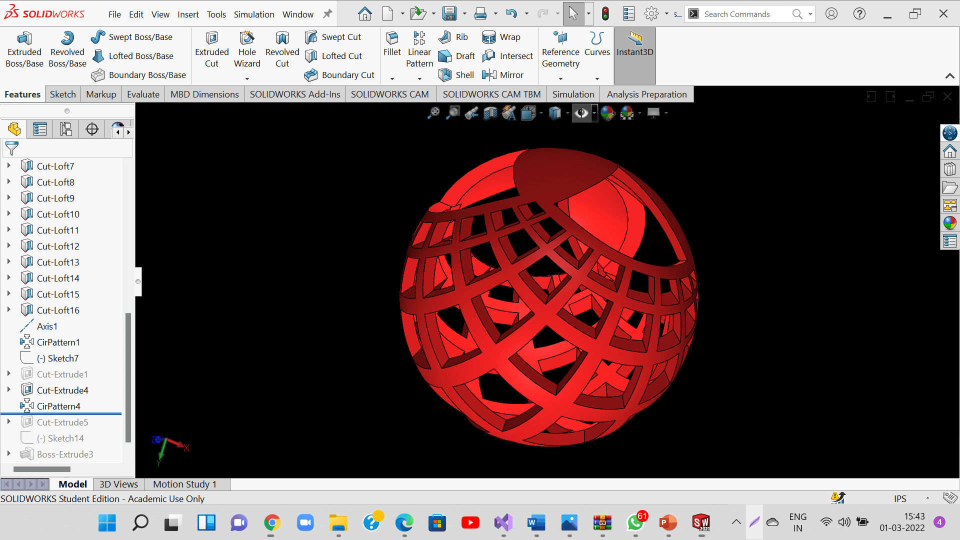
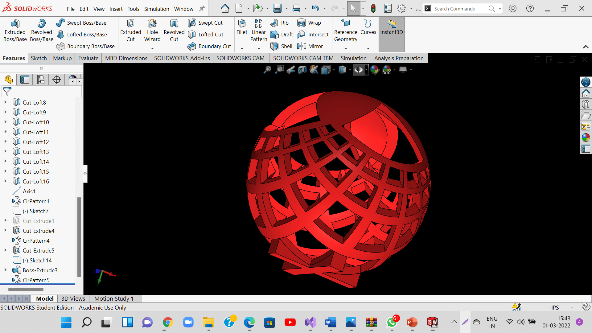
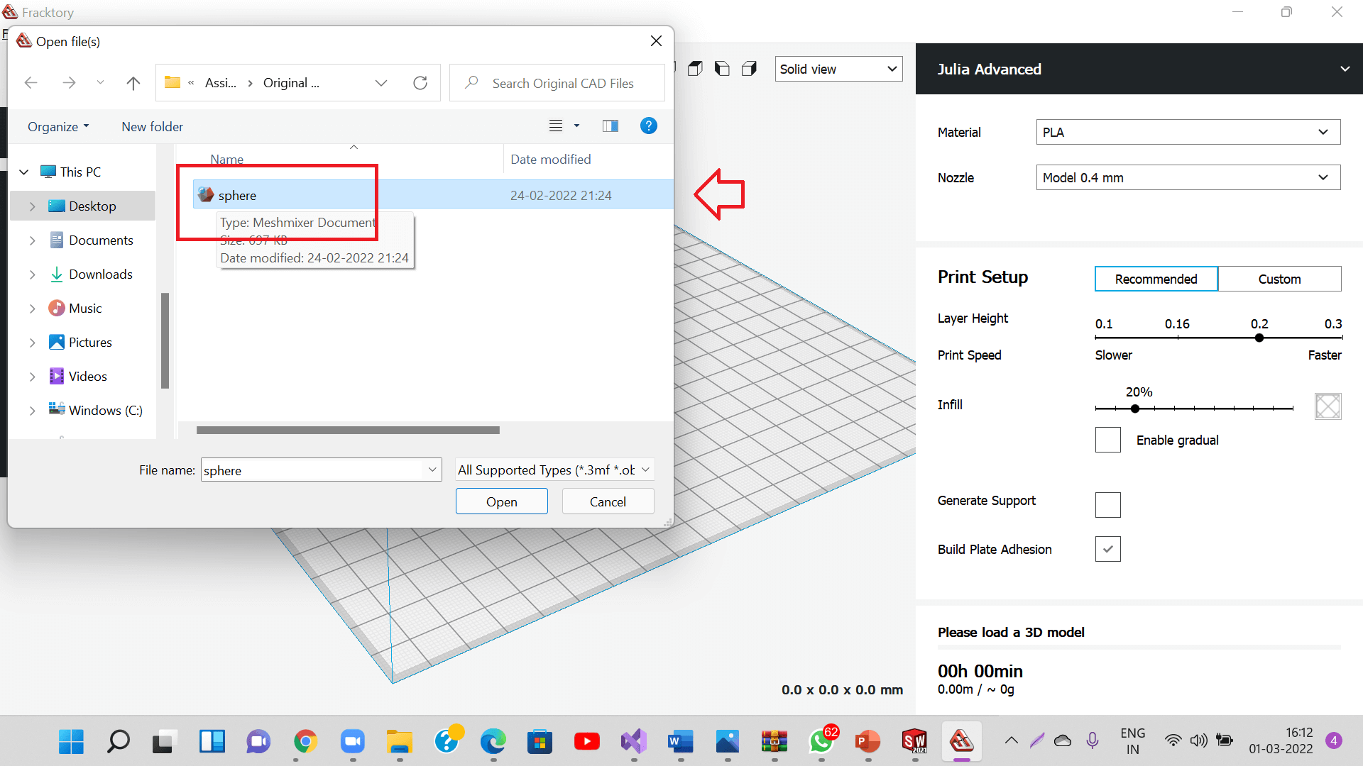
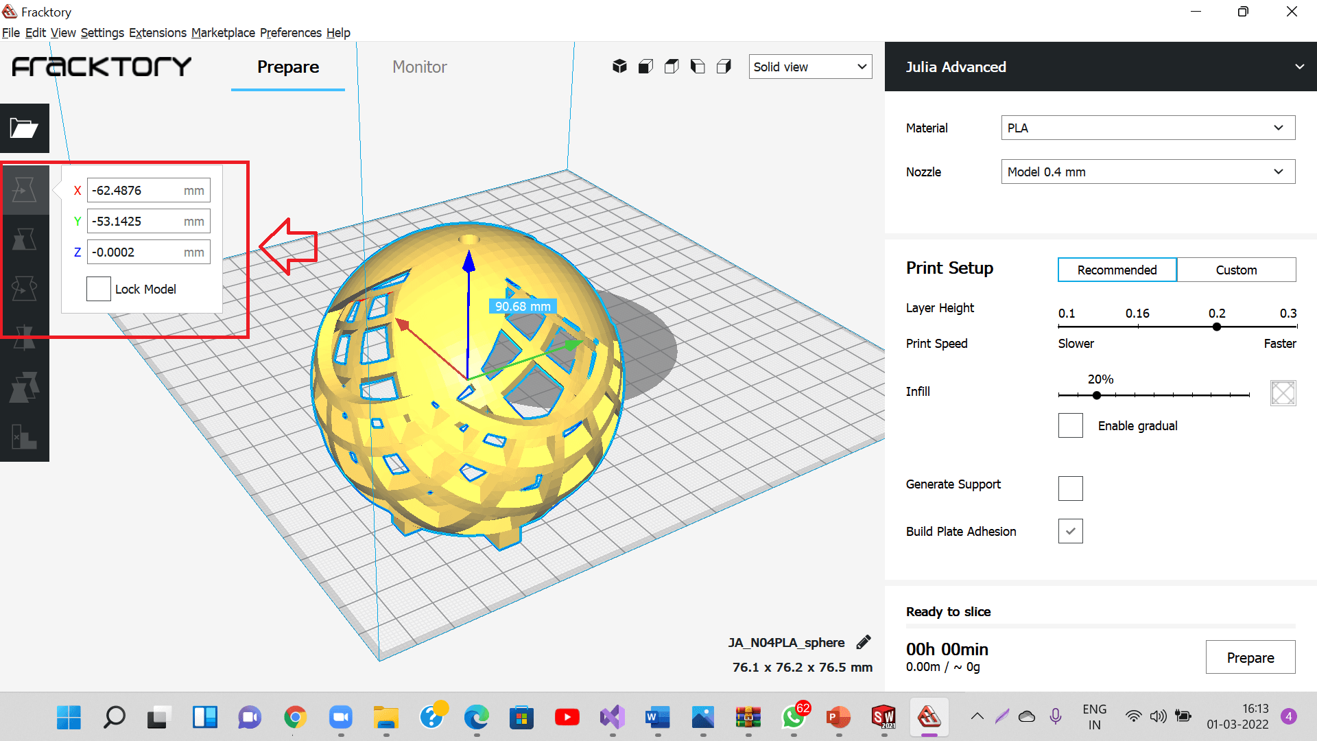
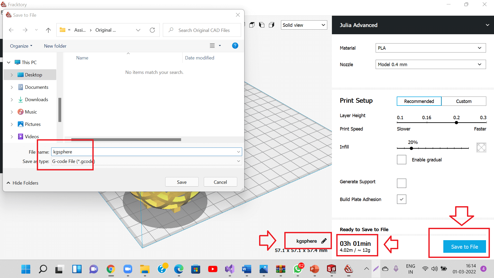
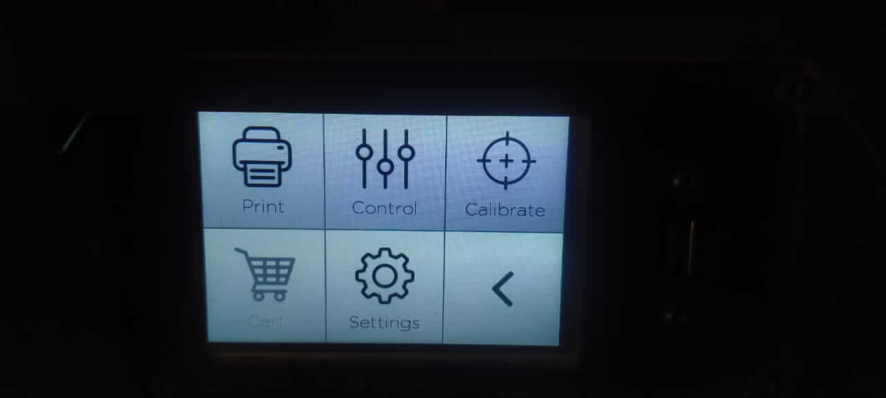
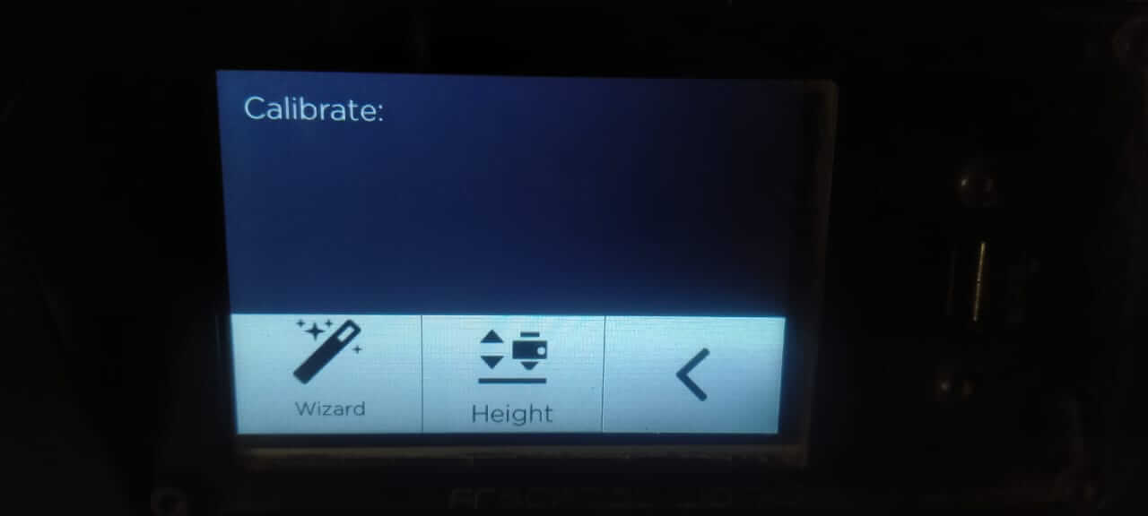
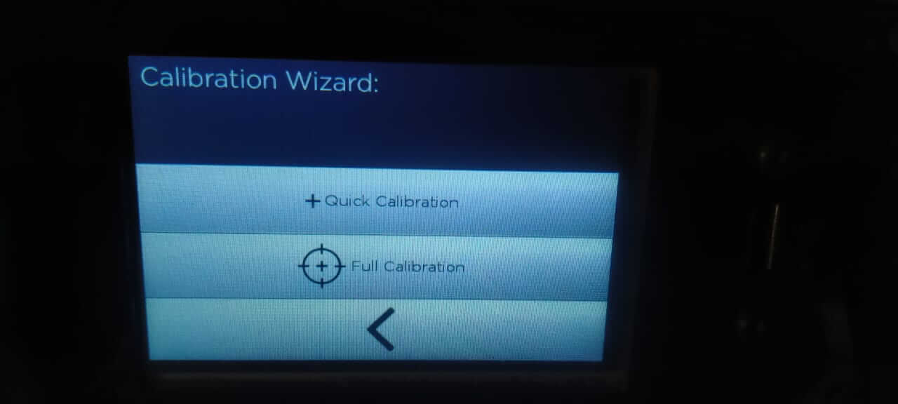
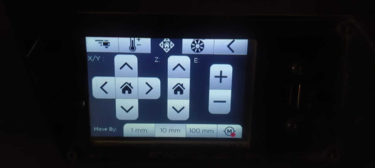
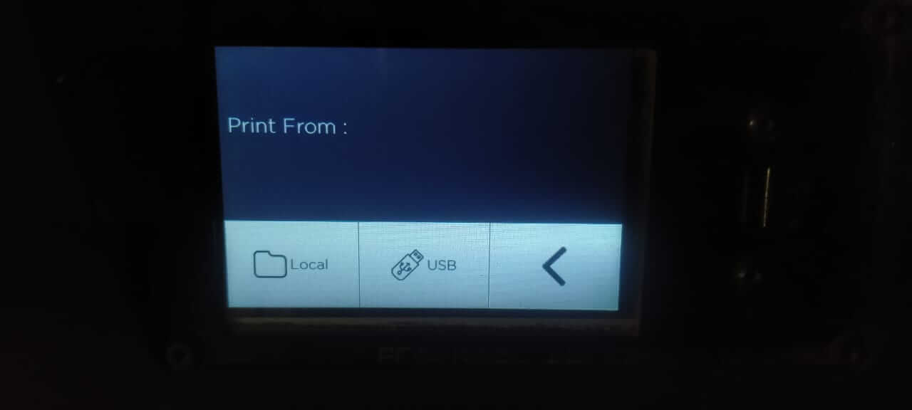
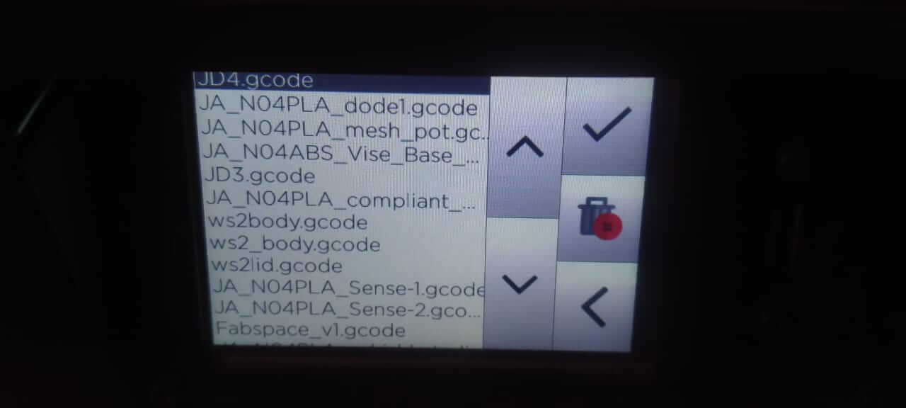
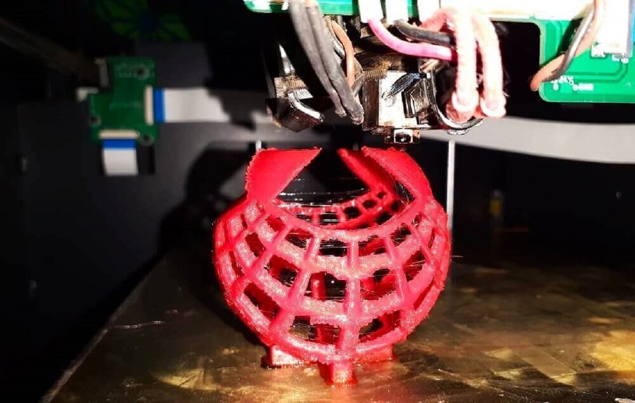
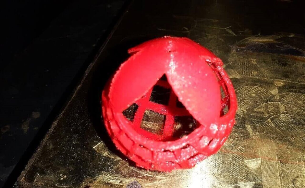
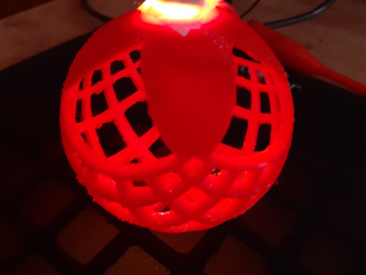
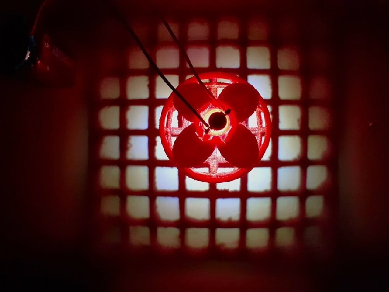
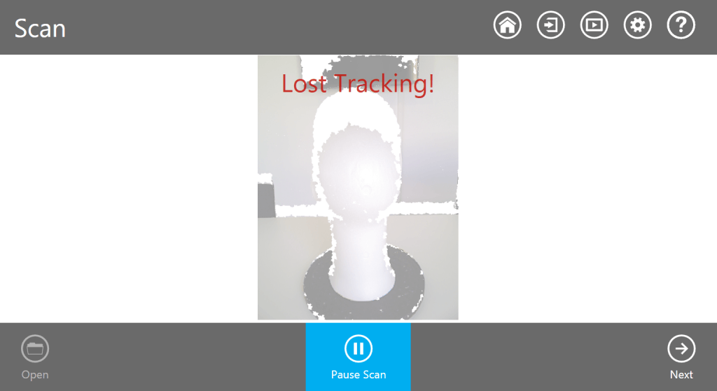
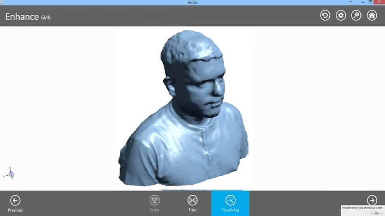
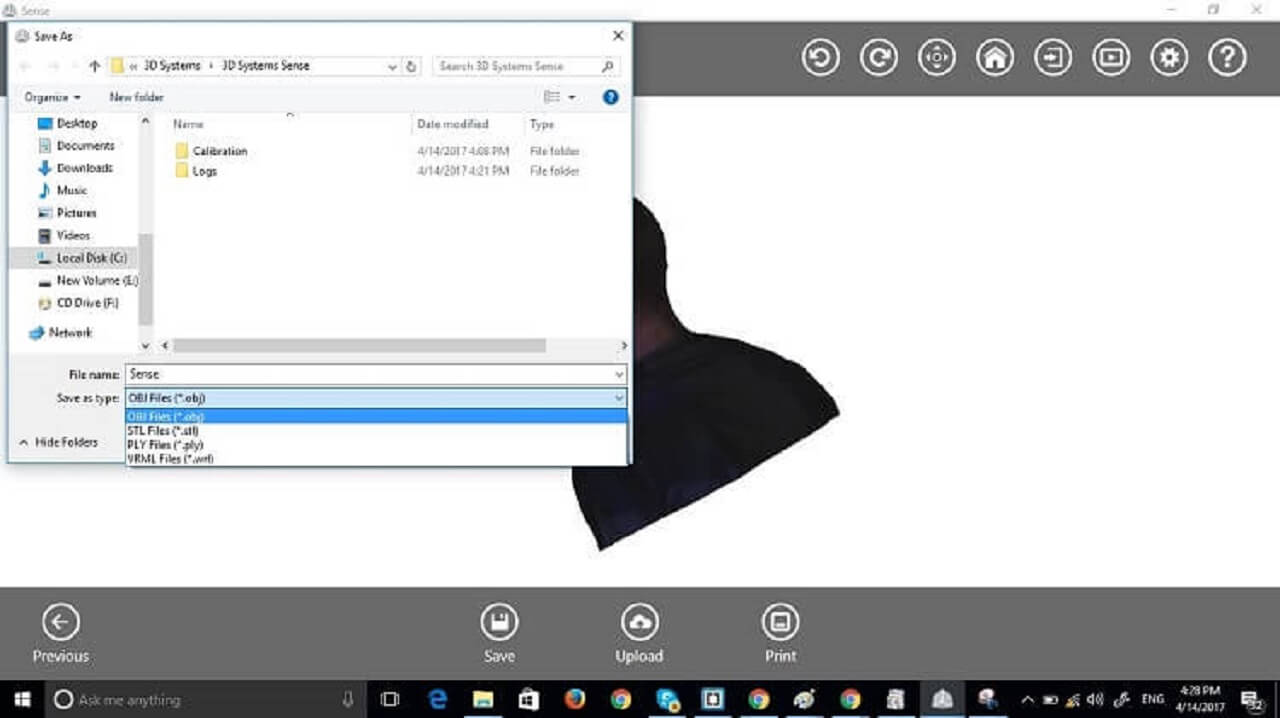
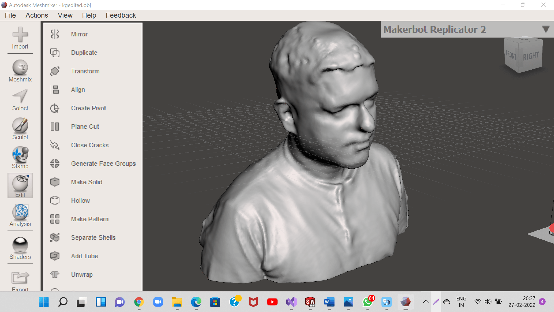
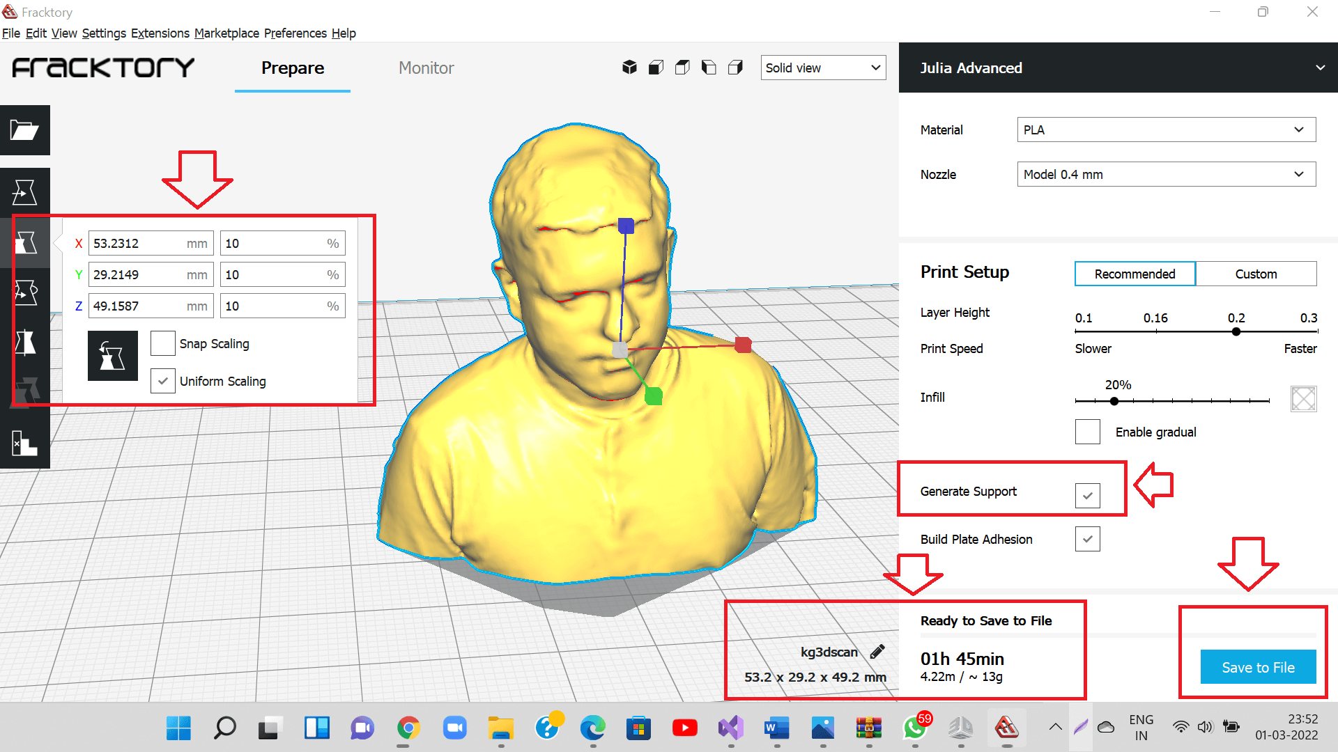
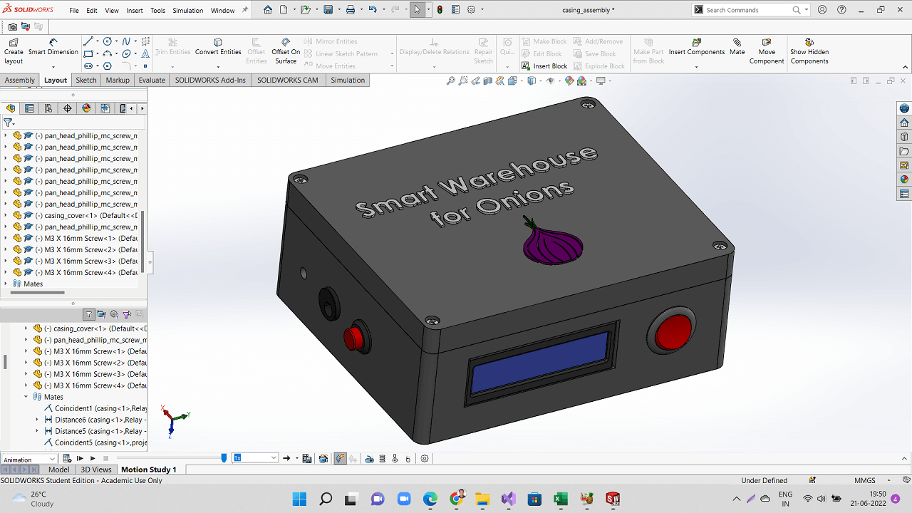
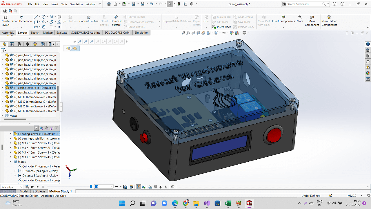
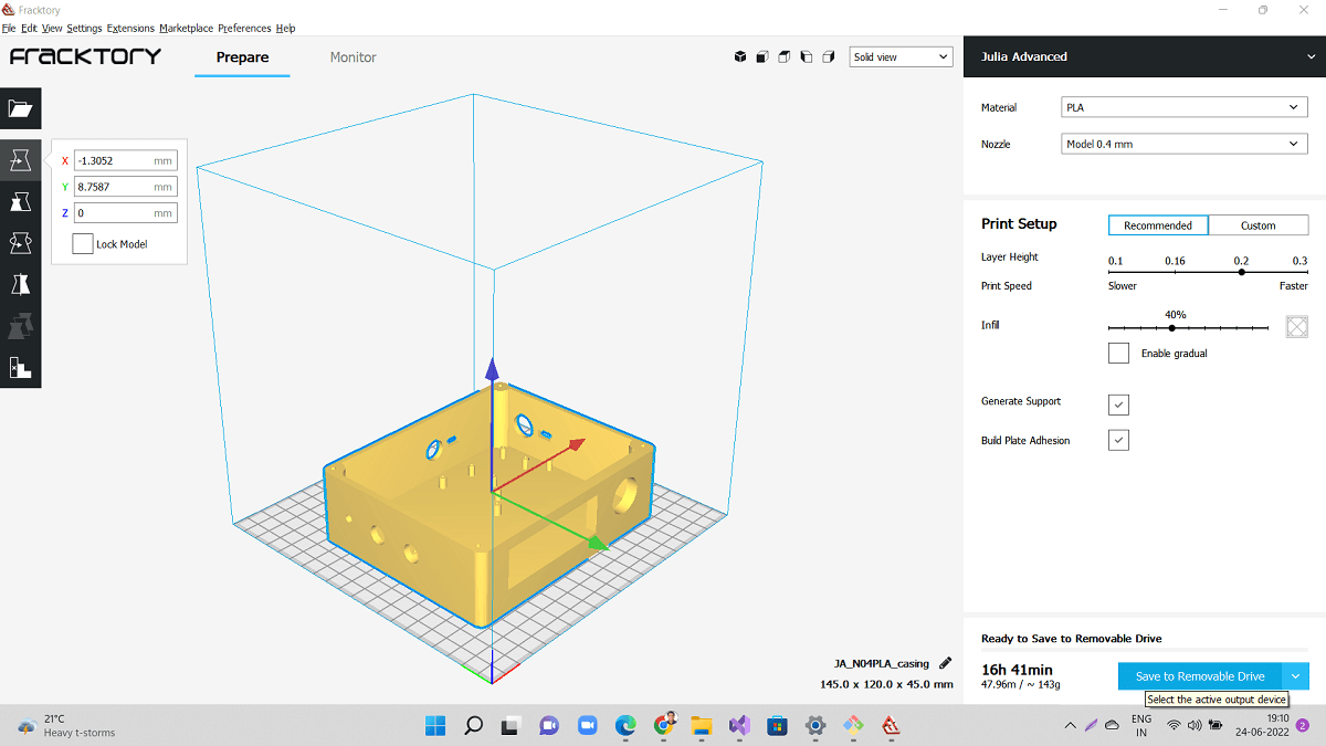
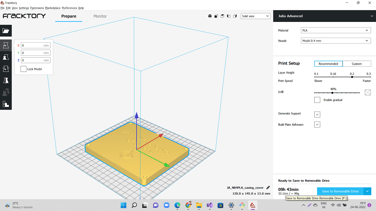
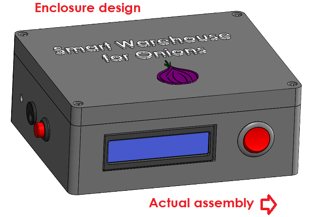
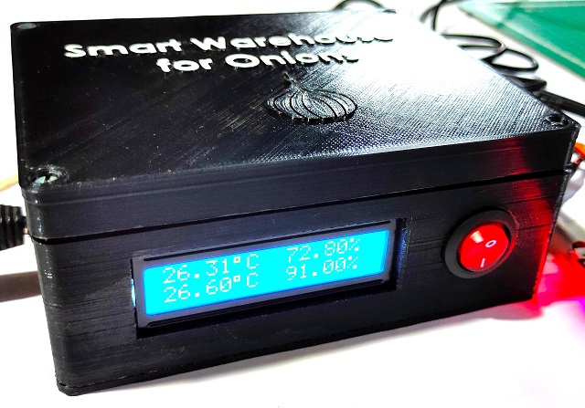
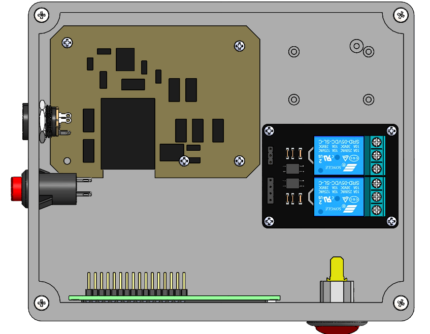
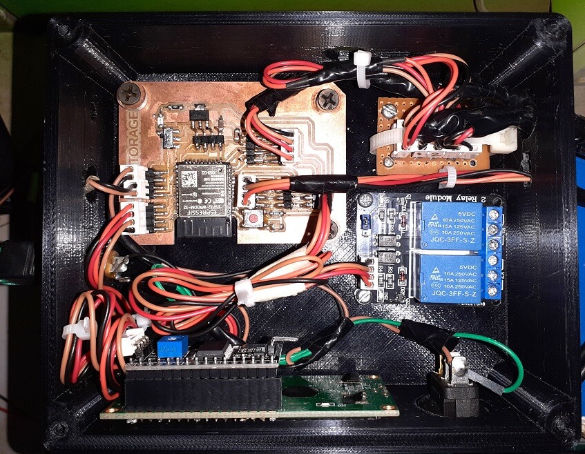
This week, we worked on 3D Scanning and Printing group assignment. This assignment is about documenting what we learned in this week regarding additive vs subtractive manufacturing, various 3D printing processes and materials, specifications of 3D printer that we have in our Fab lab. We have also documented how we used 3D printer for our group assignment, material and tools that we used, what precautions need to be taken while operating the 3D printer along with the software required for generating G code for the machine. As a conclusion we characterized the design rules for our in-house 3D printer. - Understand additive manufacturing processes, their types, materials and tools We decided to print most of the design rule components using STL files given in the academy class. We also printed one part from 3dbenchy. We also measured and analysed our 3DBenchy boat. We used PLA material for printing all these parts. We then compared our print with the reference dimensions given. First, We downloaded STL files of all the parts including 3dbenchy for generating their G-codes. We pulled each of these STL files in Fracktory slicing software to generate G-code required for 3D printer. Then, we called in STL files of a couple more parts to be printed together. We used move and rotate buttons to move parts to the desired location on to the machine bed. We chose PLA as a material inside Fracktory, 20% infill, selected nozzle diameter to be 0.4 mm as that of the machine. We clicked 'Prepare' button to generate the G-code for the job. We renamed the G-code file and saved/sent it to removable disk to be able to take the code to the 3D printer. We used PLA for our job. After setting up our 3D printer with Nozzle temperature as 210 deg C and bed temperature as 60 deg C. Following are some pictures and video of our final job we printed to test the design rules for our in-house 3D printer. I am sharing only a couple of pictures of conclusion from these jobs. Also showing below a picture of our 3dbenchy with measurements, comparison of these dimensions with the dimensions given in the original 3dbenchy file. Click here to read more about our Group Assignment. - Operate 3D Printing machine I understood the basics of the Fracktal Works Julia Advanced 3D printer before I started operating it. Following are the details of the machine. Control Panel of 3D Printer: Following are the menu on control panel of our Fractal works Julia Advanced 3D Printer. Fracktory: Slicer Software Following is a picture of the Fracktory- slicer software that I used for our Fractal works Julia Advanced 3D Printer. I decided to 3D print a sphere to be used as a Stereographic projection of a grid of 64 squares when a light beam is focused through a pinhole. I designed a sphere of 75 mm and created two reference planes, one for projecting the grid of squares and another for creating small pinhole to pass the focused lightbeam. Then I used Lofted cut command to cut the squares on a spherical surface with respect to the tiny pinhole created for focus lightbeam. I completed lofted cuts for remaining 15 out of 16 squares to be projected in one quadrant. I created a circular pattern of these lofted cuts on remaining 3 quadrants of the sphere as shown below. Finally added some extruded cuts to remove some portion on the top and added some support at the bottom for resting the sphere flat on the ground. Following are the steps I followed to generate G-code for 3D printer after slicing the 3D model I designed. 1. First, I pulled STL file in Fracktory slicing software to generate G-code required for 3D printer. Then, I used move and rotate buttons to move parts to the desired location on to the machine bed. Next, I scaled down the model to 75 percent to reduce the size of the printed job. I chose PLA as a material inside Fracktory, 20% infill, selected nozzle diameter to be 0.4 mm as that of the machine. I did not select �Generate Support� as I thought this structure can be printed without support. I clicked 'Prepare' button to generate the G-code for the job. Finally, I renamed the G-code file and saved/sent it to removable disk to be able to take the code to the 3D printer. I could also see how much time this job will take to complete the entire printing. After the G-code file was generated, it is time to set a job on the 3D printing machine through a control panel. Following are the steps I took. Calibration of the machine is important to set-up the bed perfectly flat with respect to the nozzle head. The quality of the printed job, surface finish, uniform printing, etc. are dependent on machine table being perfectly parallel and calibrated. One can do quick calibration (3 point resting) or full calibration (3 points plus 9 points resting). We can set-up temperature of the nozzle and bed from the control panel. However, it can also be set-up through G-code. The slicer software automatically selects these values based on the material selected for printing. We can set-up flow rate and feed rate of the machine from this wizard. We can move the head in X and Y direction and move the table in Z direction usins these buttons. We can take the nozzle to home position as well. There is a provision to start the extrusion of the filament in both forward and reverse direction. Forward extrusion helps us to know if the nozzle is heated enough and nozzle is clear to start the extrusion when actual printing will start. Once all the set-up is done, we can start printing. We can print directly from the USB drive or save G-code locally and print. We can also set-up machine to print through wireless connections. Following is a picture I took once my job was set for printing. At certain intervals, I then took pictures and videos of my first job being 3D printed. Finally, the wait was over and my 3D printed sphere was ready, which I can now use as a lamp to do stereographic projection. After cleaning of the job, I put on some LED and checked how stereographic projection looks like in the dark. However, I realized I needed 1W LED for single beam focused bright light. After I added 1W LED with 9V battery, I got bright illumination and focused beam, you can see how beautifully the grid of 64 squares is projected through the sphere. When I measured the size of the shadow, it came exactly as I designed in the software. So, it was very important in solid modeling, where I draw the working and projecting planes. I am now planning to add flexible circuit to avoid the wired connections, they do not look that good :) Lastly captured a perfect picture. Felt so joyous. We used 3D Sense scanner for this assignment. Following are the details of the scanner. First, I downloaded the 3D Sense software from here. In the next screen, we get options-either to scan the head portion or to scan the entire body as shown in the image below. As mentioned earlier, we scanned each other as shown in the pictures below. If we do not hold the scanner properly (in correct height, angle and continuous focus on the person/object), it loses the track and we have to restart the scanning process. So, we need to careful in scanner orientation until complete scanning is done. In our case, where we scanned persons, we were holding the scanner in one position and the person was rotating around himself in front on the scanner. Once the scanning was done after one complete rotation of the person, we stop scanning and then process the scanned model inside the software. We can trim, color, touch-up the model before we save it as shown in the pictures below. I then downloaded Meshmixer software (From Autodesk) from here. I used it to do additional touch-ups and edits to the scanned object file as the 3D sense software do not have many options for editing. I saved this file as OBJ file. Next, I pulled this OBJ file in to the Fracktory slicing software to generate G-code for the 3D printer. I scaled down the model to 10% to fit the 3D print in 5cm x 5cm x 2cm dimension. I added supports to the model before I renamed and saved the G-code file. Imported this G-code in Fractal works Julia advanced 3D printer to print and Ta-da there I have my own 3D printed mmodel. Finally, I am again adding the video that I created for entire work on my individual assignment for this week. You can see how I varied intensity of the light to get different effects of the projected light I designed the enclosure in solidworks for 3D printing it. I assembled 3D CAD models of my board, LCD, 2 channel relay, buttons, power jack socket, etc. to ensure I have optimum space for assemblying the actual components inside the box. I did slicing in fraktory software for generating toolpath for 3D printing as shown below. Short video on 3D Printing of casing for final project. Following are the pictures of enclosure designed and actual enclosure I 3D printed and assembled. I arranged these two pictures side-by-side to compare designed vs actual assembly. Following are the pictures of system integration- design vs actual. In group assignment- Out first two parts did not print nice. We changed the G-codes a couple of times, we changed the orientation and location of the parts in the bed, may be there was calibration issues earlier. There on, the group assignment parts were printed well. We printed 4 parts together in the end. We also used 3dbenchy for testing designs on our printer. In group assignment- As I said earlier, there was bed calibration issues, the first two parts did not print well. With limited time on hand, not everyone could print group assignment parts separately. We had to print 4 pf the parts together. - I could have 3D modelled my individual assignment earlier in my free time, it would have saved some time. Also, better planning of group assignment is needed. - I learned how to set-up the 3D printer including setting up the filament and temperature settings. I also learned PLA is environment friendly material to be used in 3D printing
Objectives of the Group Assignment:
- Understand how to operate the 3D printer
- Learn safety precautions while operating this Machine
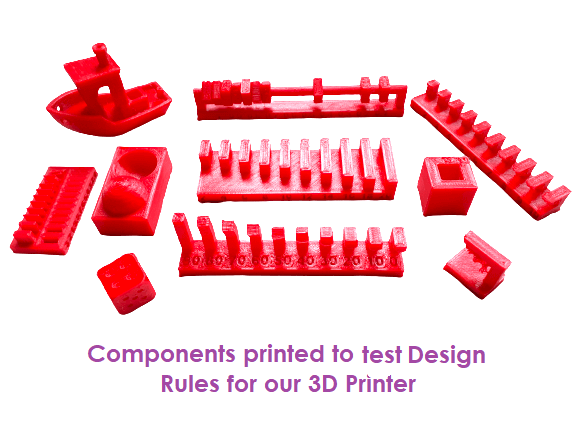
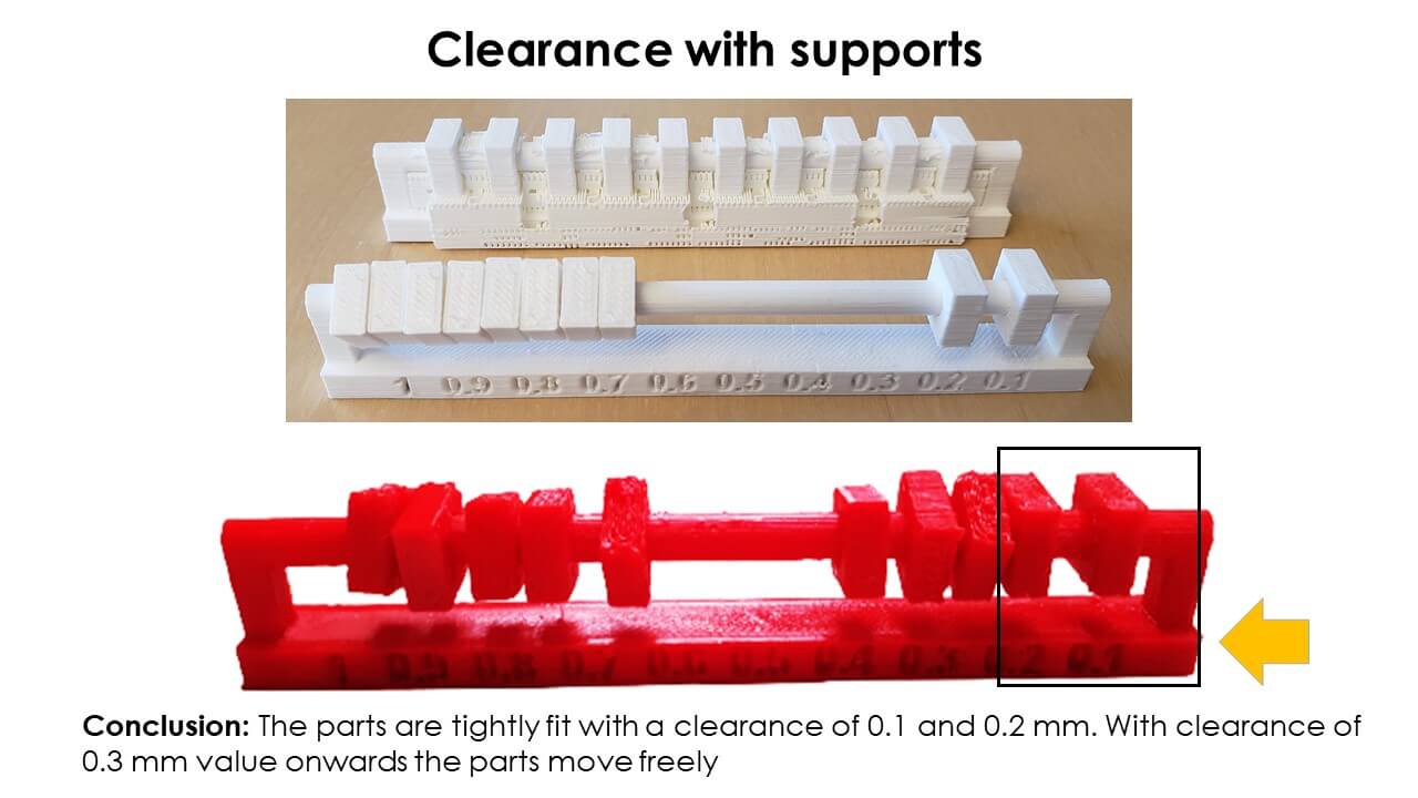
- Test the design rules for our in-house 3D printerTesting Design Rules for our 3D printer
Generate G-code for 3D printing

Conclusions from this assignment:
Click here to go back to the topIndividual Assignment
Objectives of Individual Assignment:
- Learn settings and safety precautions of the machine
- Design and 3D print an object (small, few cm^3, limited by the printer time) that could not be made subtractively
- 3D scan an object (and optionally print it)
3D Printing
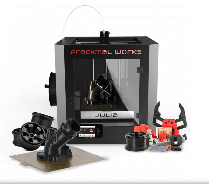
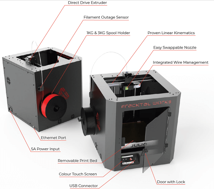
Fracktal Works Julia Advanced 3D printer: With a fully integrated system of hardware, software and materials, it is the most reliable, innovative and easy to use 3D printer on the market. An all-in-one solution that combines precision linear motion, integrated high-end electronics, heating and material management systems in a beautiful aesthetic design Click to know more
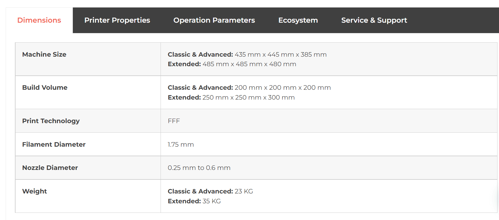
Printer Dimensions
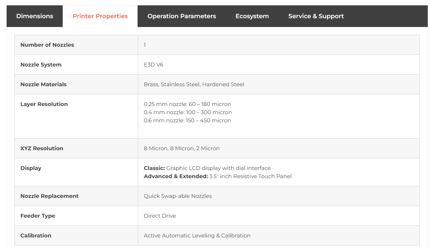
Printer Properties
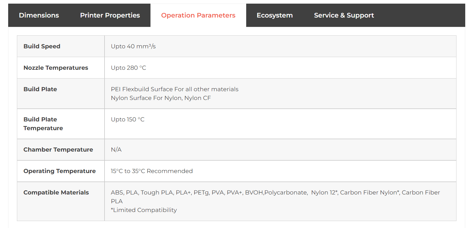
Printer Operation Parametes
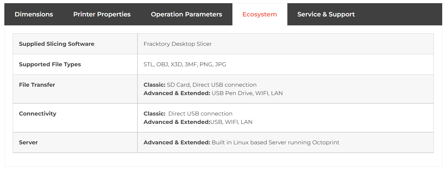
Printer Ecosystem

3D Modeling of the job to be 3D printed
Used Solidworks for 3D modeling: I used circular pattern, lofted-cut features in Solidworks to create what I wanted to 3D print.

Slicing and Generating G-Code


Setting up the 3D Printer


Click here to go back to the top
Download CAD File
Click here to go back to the top
3D Scanning
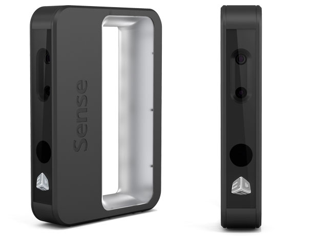
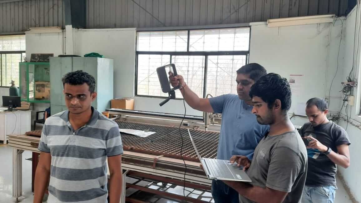
3D Systems Sense 1 Scanner: The Sense 3D scanner delivers best-in-class accuracy of close to 1 mm with resolution at 1 mm and an unprecedented color resolution of 1920 x 1080 for perfect color texture mapping. Sense has a generous scan range of between 7 and 72 inches to allow rapid 3D scanning of a wide range of objects. The Sense 3D scanner includes the Sense software to rapidly edit your 3D scan data, solidify for immediate 3D printing and save data out to four industry-standard file formats for downstream uses. Features Capture your world in 3D Mash-up your world Big or small, scan it all Zero-in on what matters Edit with ease Physical to digital and back again
Wide Applications: For family- scanning memorable moments in your home and print them out in color 3D, making our good memories come in three dimensions; For education- Teachers can enable students to perceive the world from a 3D perspective; For design- you can get safe and precise data quickly, can easily edit and save your creative data, making your design process smoother and more efficient; For 3D photo studio- can make exclusive 3D portraits for you, funny and special; Besides, this technology will have great application prospect in the future.
Features: High Precision and Fast: Objects can be automatically identified, pinpoint lock the scan target, then capturing necessary data information accurately, save and archive 3D data of artifacts quickly, making scan process becomes easy and fast. Safe to Human Body: Light is harmless to the user's eyes, without direct touch to the the person or object being scanned, more secure. Portable and Practical: Handheld design can be put on desktop, can be packed into a laptop bag, holding from one place to another, indoors or outdoors, so you can scan data anywhere, especially suitable for service; Also can be attached to a tripod, big or small, scan it all, so easy to carry and convenient to use. Click to know more.
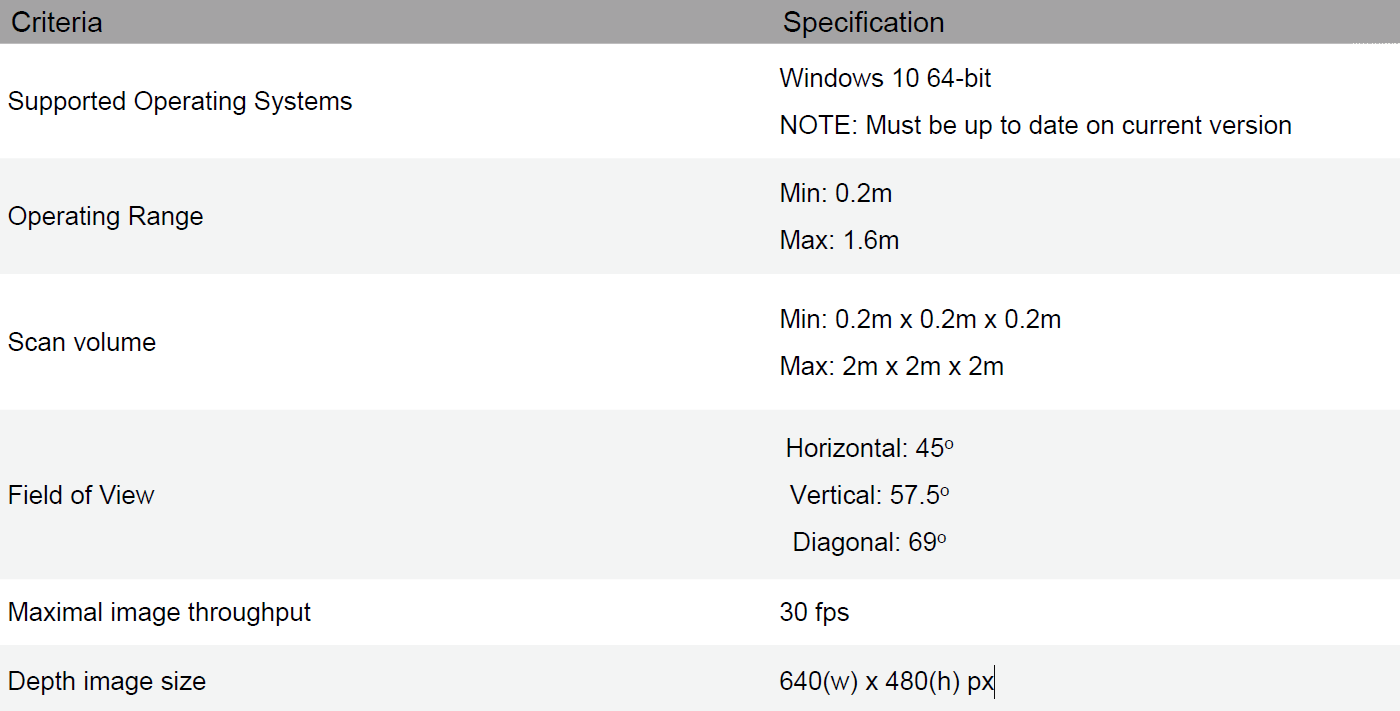
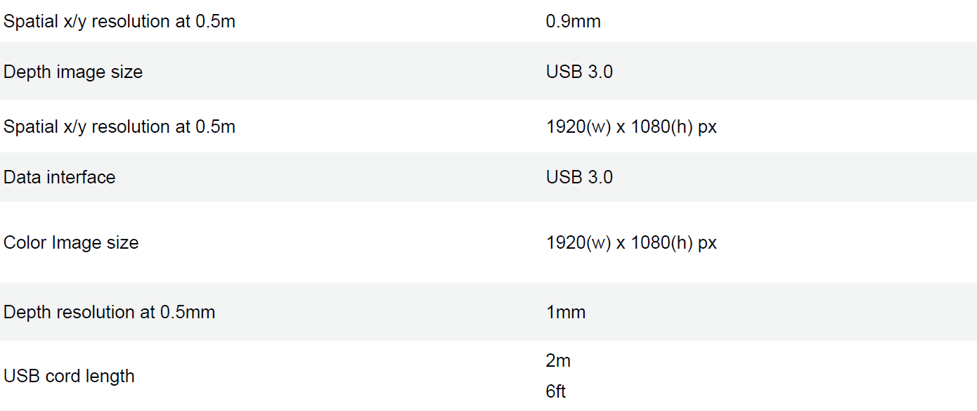
Scanner Specifications
Click here to download the 3D Sense manual.
Scanner Hardware Recommendations

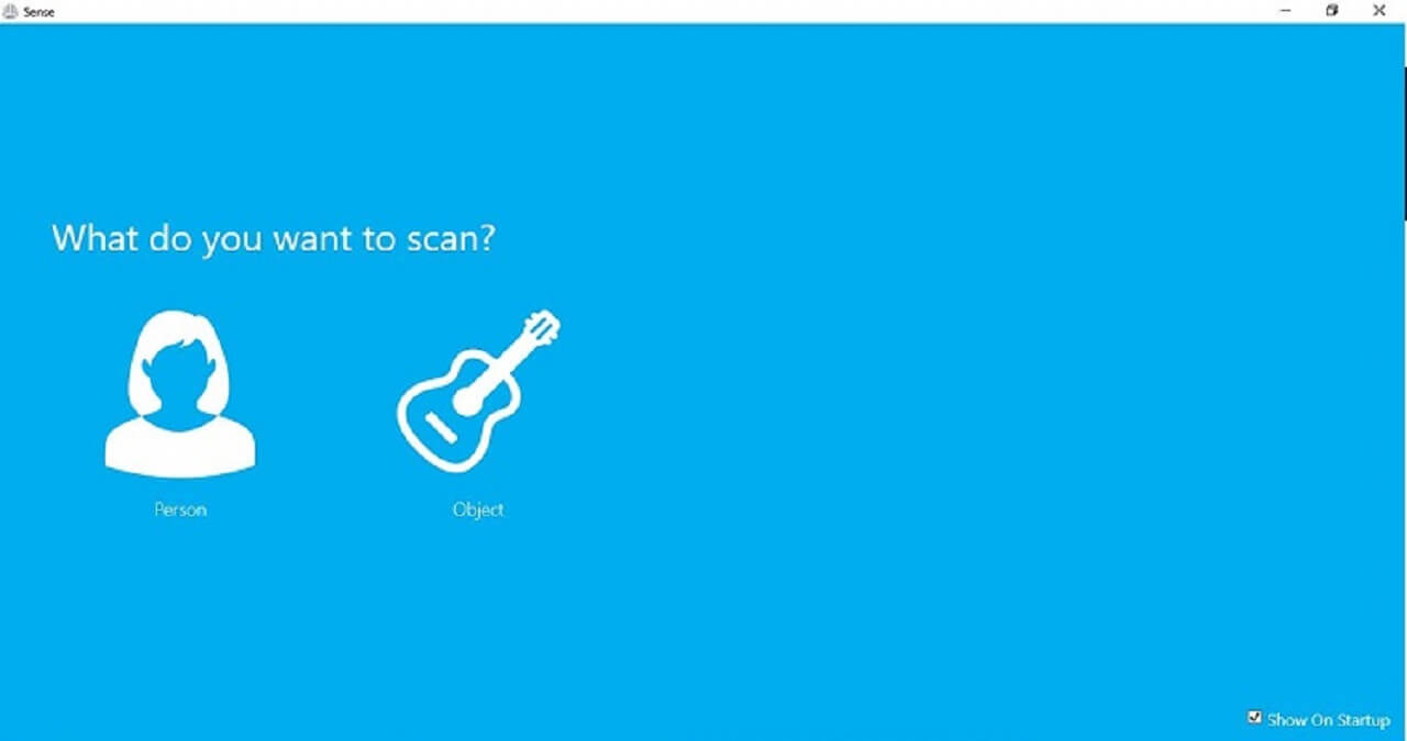
How did I use 3D Scanner
Then I attached the scanner to my laptop, opened the software and activated it with a code. Planned to scan a person. In our group, we decided to scan each other. That way, we will learn to operate the scanner and also will get everyones scanned model.

Click here to go back to the top
3D Printing for Final Project
Following is a picture of the CAD model that I designed for 3D printing the enclosure for electronics of the system.
Click here to go back to the top
What went well
In 3D Printing individual assignment- I was able to design 3D model of stereographic projection quite in time. That gave me enough time to print the job. First two times, I was doing something wrong with machine calibration but I could resolve that later and my first few passes of material extrusion were successful. After the job was done, I used a 2V LED, which was not giving enough illumination but then changed that LED to point focus 1W LED. It worked nice.
In 3D Scanning individual assignment- Multiple trials on 3D scanner helped in understanding its working principle. Initially, we did scanning of non-living object while we were revolving around the object. We realized that for scanning of a person, it is better if we keep the scanner steady and person rotates.What went wrong
In 3D Printing individual assignment- I did not set-up the plate on the bed properly, it was not locked in to the slots and I struggled doing calibration. I did quick calibration once and it did not work, I did full calibration twice but that too did not work. After spending about 45 mins in this, I realized, I had not placed the plate properly, it was unevenly placed. Also, after my job was done, I wanted to put up LEDs to make it a lamp, I blew off a couple of LEDs because of high voltage. I added resistor and a heat sink later.
In 3D Scanning individual assignment- I was not able to hold the scanner at a proper angle and steady, my hands were shaking. Scanner lost the objects out of the track. Later, we used tripod. Also, we changed our scanning location a couple of times to find optimum illumination. Earlier, it was either too dark or too bright for the camera. Also, I could not stop scanning after one rotation, it appeared that, it scanned the persons same area multiple times. I corrected it and the next scans were successful.What I would do differently
- I could use flexible circuit inside my 3D printed stereographic projection lamp to avoid wired connections, which spoiled the view to some extent.Learning Outcomes
- I learned the importance of machine calibration in 3D printing, it improved quality, surface finish of the printed job
- I also learned the importance of placing plate on the bed properly and how to remove printed part safely and clean the plate using alocohol after printing is over. I should not use sharp tools to remove the parts, it may scrape the surface of the plate.
- I learned why and how to use 3dbenchy for testing design rules for the printer
- I used sketchfab for the first time to upload my own design. I also learned how to make changes in to the link for sketchfab embed to make its ration 16:9 to match that of the other media files in the document. I made some changes to my css file and also the iframe tag
- I can now operate 3D printer and 3D scanning independently
- I learned meshmixer software this week