Assignment#3: Computer controlled cutting
This assignment is about documenting what I learned in computer controlled cutting that includes laser cutting and vinyl cutting. I have also documented how I used laser cutting to make my own construction kit. I am also documenting what I learned in parametric design and its importance in laser cutting. I also had a hands-on experience on other CAD applications for paper unfolding like blender, pepakura. I am also documenting what went well, what went wrong, how I would do things differently in next assignment and my learning outcomes.
Laser cutting is a technology that uses a laser to vaporize materials, resulting in a cut edge. While typically used for industrial manufacturing applications, it is now used by schools, small businesses, architecture, and hobbyists. Laser cutting works by directing the output of a high-power laser most commonly through optics. The laser optics and CNC (computer numerical control) are used to direct the material or the laser beam generated. A commercial laser for cutting materials uses a motion control system to follow a CNC or G-code of the pattern to be cut onto the material. The focused laser beam is directed at the material, which then either melts, burns, vaporizes away, or is blown away by a jet of gas, leaving an edge with a high-quality surface finish. Click here to read more.
While, A vinyl cutter is an entry level machine for making signs. Computer designed vector files with patterns and letters are directly cut on the roll of vinyl which is mounted and fed into the vinyl cutter through USB or serial cable. Vinyl cutters are mainly used to make signs, banners and advertisements. Advertisements seen on automobiles and vans are often made with vinyl cut letters. While these machines were designed for cutting vinyl, they can also cut through computer and specialty papers, as well as thicker items like thin sheets of magnet. In addition to sign business, vinyl cutters are commonly used for apparel decoration, manufacturing wearables using fabric. Click here to read more.
What is 2D, 2.5D and 3D cutting machine?
2D cutting machine cut 2D shape. Wherein, with 2.5D machine, we can cut our 2D drawing and can adjust Z axis according to our materials thickness. Whereas, with 3D cutting machine, we have complete control on all three axis and can cut 3D design on it.
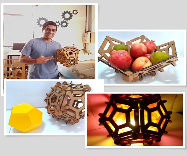
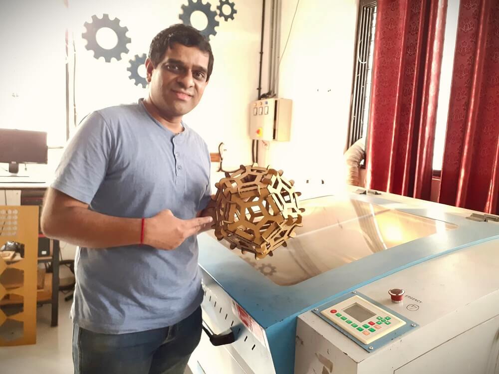
Below are few of the Hero Shots of my work on laser and vinyl cutting as a part of individual assignment.
 |
 |
 |
Click here to go back to the top
Group Assignment Brief
This week, we worked on Laser cutting and scanning group assignment. We divided ourselves in 3 groups and conducted various trials on laser cutting machine.
Objectives of the Group Assignment:
- Understand the Laser cutting machine, its specifications
- Understand how to operate the machine
- Learn safety precautions while operating the Laser Cutting Machine
- To find out the optimum speed and power values along with calculating the Kerf value for various materials
These values are now helpful for us while working on laser cutting for our individual assignments and project. Once we have optimum speed, power and Kerf values, we can modify our CAD models parametrically based on these values. Then, we calculated kerf values for different materials in detail in this group assignment.
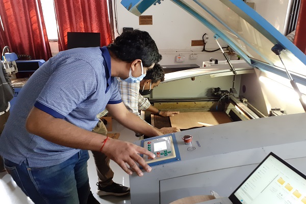
I was a part of a team working on Plywood and MDF material. We distributed the tasks amongst ourselves. I worked on engraving (designning to actual machine operation and documentation) while my team members worked on cutting (designning to actual machine operation and documentation). Below is a summary of what my team did in the group assignment.
Plywood and MDF cutting
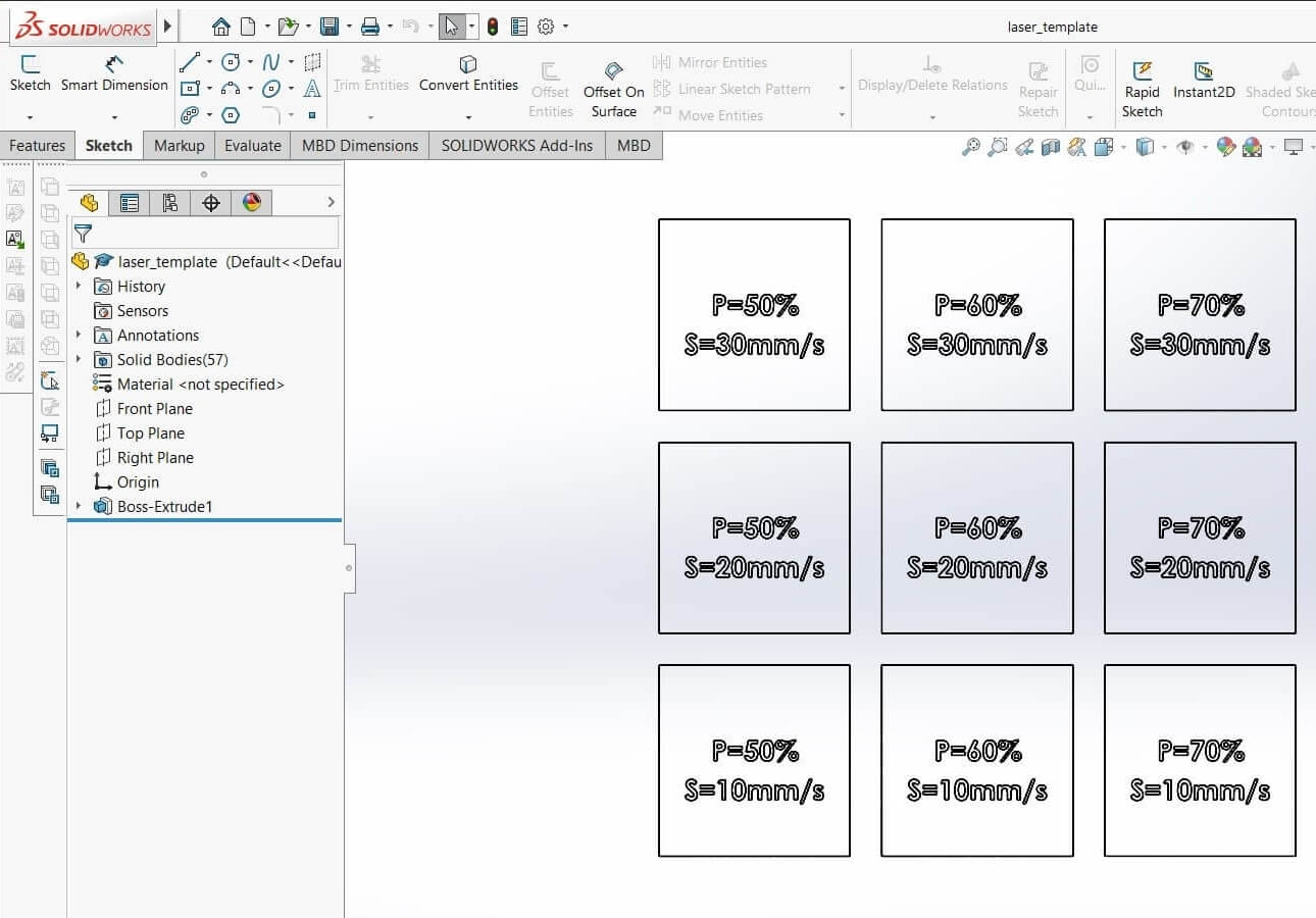
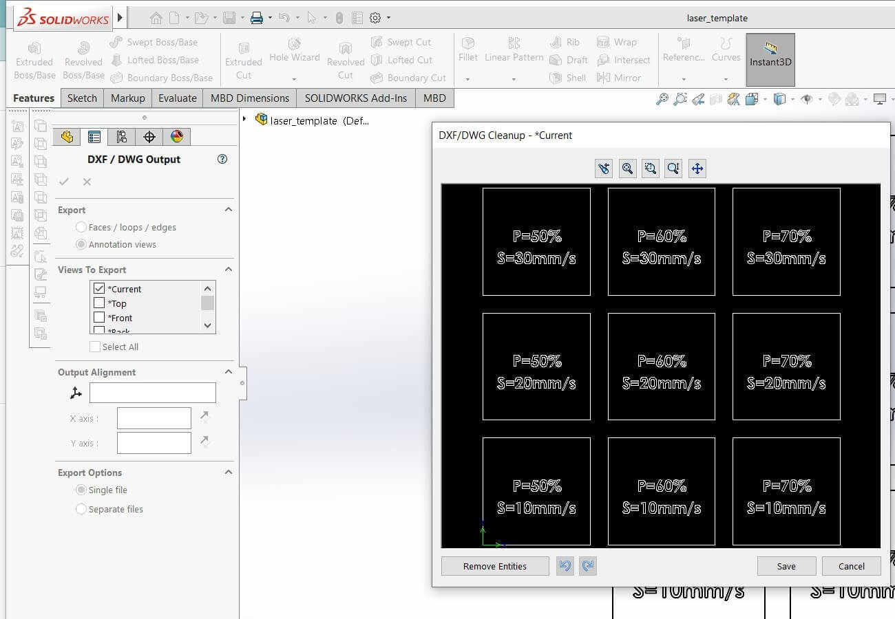
Preparations: Selected a 4 mm thick plywood and MDF sheets. To find out how the machine would work with different speed and power settings for both plywood and MDF, the team designed a sketch in solidworks. Generated a dxf file, which was imported in RDWorks. Below are the snapshot of the sketch and dxf file. Then, we assigned different colors to the cutting paths in RDWorks where each color represents different speed and power.
 |
 |
Results and conclusion:
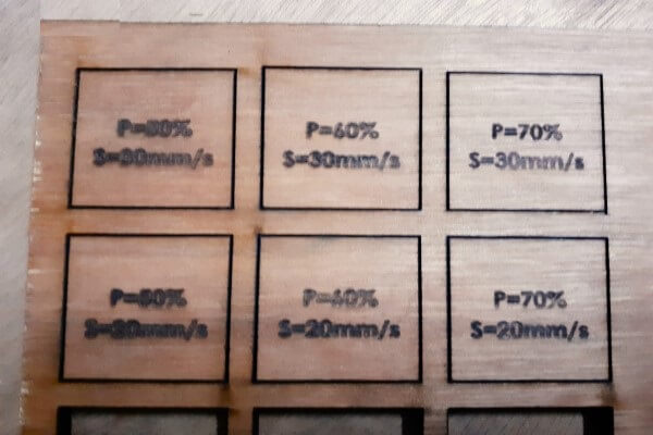
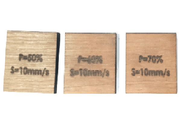
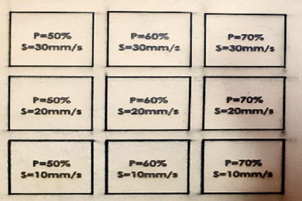
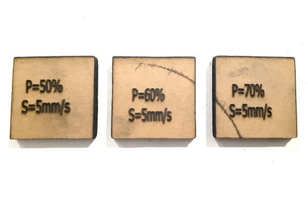
Below are the pictures of the plywood and MDF sheets that we used for cutting operation. The right most images in both the rows of pictures below show the through cut pieces. The left most images in both the rows show that the machine was not able to cut through the sheets at those settings. Looking at the results, we concluded that for a 4 mm plywood sheet, if we want to cut with a speed of 10 mm/s, we will need to use 50% - 70% of the power. If we want to cut a 4 mm MDF sheet, we need to reduce the speed to 5 mm/s with 50% - 70% of the power for material to cut through. We can not cut plywood at a speed of 20 mm/s and above. Similarly, MDF can not be cut at 10 mm/s and above.
 |
 |
 |
 |
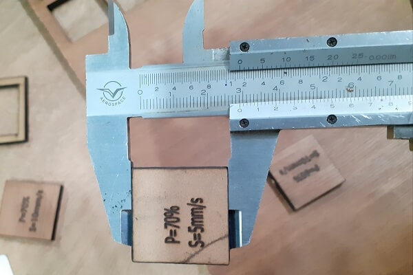
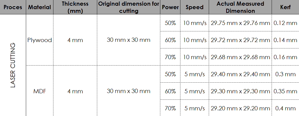
Then we calculated the kerf for 4 mm plywood and MDF sheets by measuring the actual dimensions and comparing them to the designed dimensions. The difference between these two dimensions gave us the kerf value. The more power we use, more will be the kerf value.
 |
 |
Plywood and MDF scanning
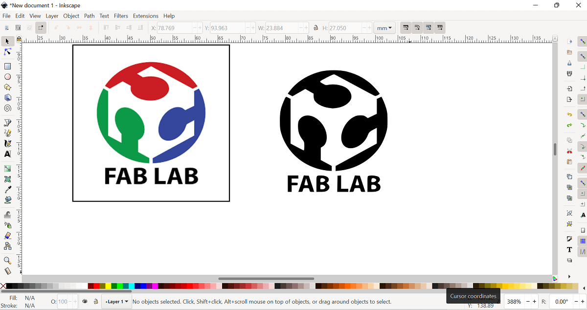
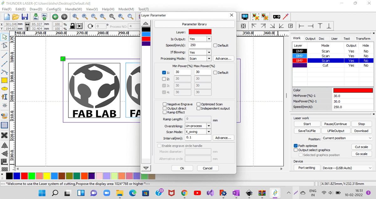
Preparations: We used 3 mm thick plywood and MDF sheets. To find out how the machine would work in scanning/engraving with different speed and power settings, the team created one dxf file in Inkscape for plywood and MDF both. It was then imported in RDWorks to apply speed and power settings. Below are the snapshot of the dxf file and layout in RDWorks.
 |
 |
Results and conclusion:
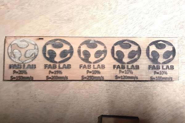
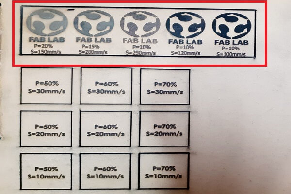
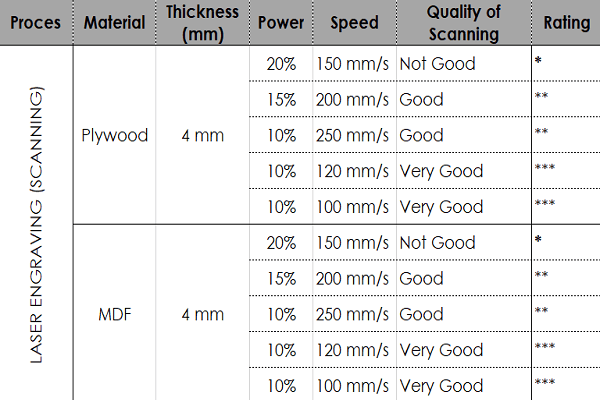
Below are the snapshots of plywood and MDF sheets with engraving done. Looking at the results, we concluded that for 4 mm plywood and MDF sheets, the machine was able to engrave with a very good quality at 100 - 120 mm/s speed and 10% power. As we increased the power and reduced the speed, it resulted in deep engraving with poor quality of engraving. Similarly, with low power and high speed also, the quality of engraving was good, it was not that bad.
 |
 |
 |
Click here to read more about our Group Assignment.
Click here to go back to the top
Individual Assignment
Objectives of Individual Assignment:
- Understand the basics of Laser cutting
- Design, lasercut, and document a parametric construction kit, which can be assembled in multiple ways
- While designing a construction kit, account for the laser cutter kerf derived from the group assignment
- Cut something on the vinyl cutter
- To learn additional CAD tools like Blender, Pepakura to create paper unfolding models
 |
 |
Basics of Laser cutting:
What is Laser: A laser is a device that emits light through a process of optical amplification based on the stimulated emission of electromagnetic radiation. The term "laser" originated as an acronym for "light amplification by stimulated emission of radiation". (Source: Wikipedia)
What is CO2 Laser: The carbon dioxide laser (CO2 laser) was one of the earliest gas lasers to be developed and is still one of the most useful types of laser. Carbon dioxide lasers are the highest-power continuous wave lasers that are currently available. They are also quite efficient: the ratio of output power to pump power can be as large as 20%. The CO2 laser produces a beam of infrared light with the principal wavelength bands centering on 9.6 and 10.6 micrometers. (Source: Wikipedia)
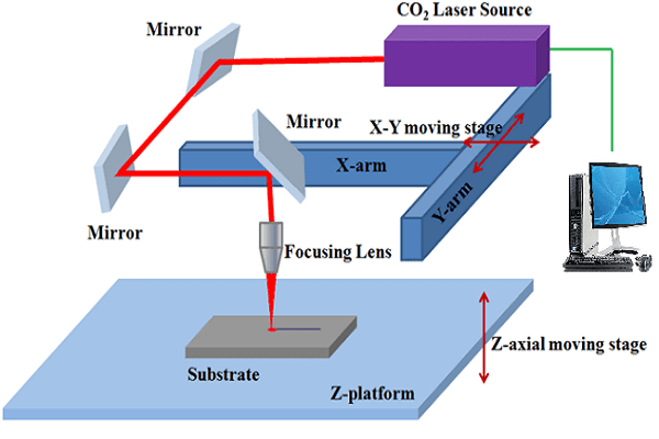
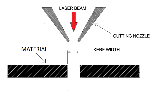
What is Laser cutting: Laser cutting is a technology that uses a laser to cut materials, and is typically used for industrial manufacturing applications, but is also being used by schools, small businesses, and hobbyists. Laser cutting works by directing the output of a high-power laser most commonly through optics. The laser optics and CNC (computer numerical control) are used to direct the material and the laser beam generated. It is necessary to know the principle and schematic of a laser cutting machine (see the image below), details of the laser cutting machine, machine specification and precautions to be taken while operating the machine, important parameters of laser cutting operation like speed, power and every laser cutting operation has a kerf value associated with it. Before we go any further, we need to know more abour kerf:
What is Kerf in laser cutting: When a laser cuts through a piece of material, the lasers own width displaces a little extra material than is specified in the original design. The amount of material that is burned away is known as the kerf in laser cutting (see the image below). The size of the kerf depends on the laser being used and the material being cut. It not only changes as per each material, but it changes based on speed, beam power, cutting geometry, assist gas and a few other factors.
Schematic of a Laser cutting and Kerf
 |
 |
Parametric Designing:
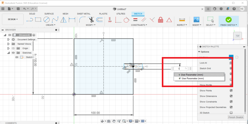
Parametric designing or modeling is a computer aided design (CAD) software design tool that saves time. It eliminates the need for a design engineer to constantly redraw a design every time one of the design dimensions change. One of the most important features of parametric modelling is that attributes that are interlinked automatically change their features. In other words, parametric modelling allows the designer to define entire classes of shapes, not just specific instances.
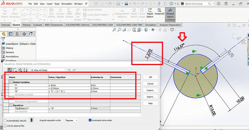
Parametric modeling is very much necessary in Laser cutting operation. Considering the kerf in laser cutting, we need design our slots in laser cut press fits joint by compensating the kerf. The slot dimension depends upon two parameters- one, material thickness and second one is kerf. Since, these two parameters keep changing by change in material, speed and power settings, etc., the slot dimensions need to be changed. However, the designer need not keep on changing all dimensions one by one. We can use parametric modeling in defining the slot width by considering the material thickness and kerf.
So, it is important for me to learn parametric modeling for creating the sketches for laser cutting. I practised parametric modeling in both Fusion 360 and Solidworks. I used solidworks to create my press fit joints for designing a construction kit.
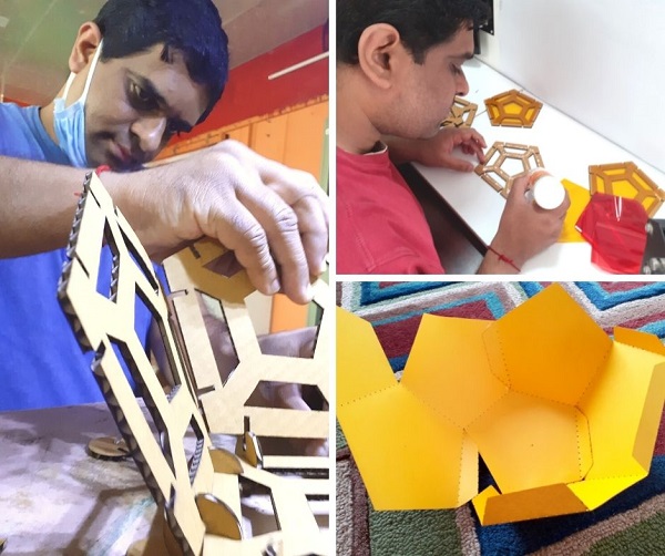
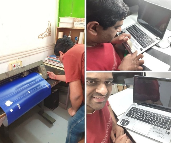
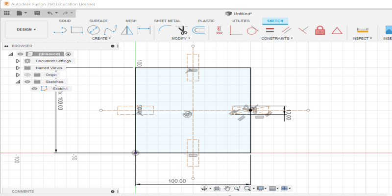
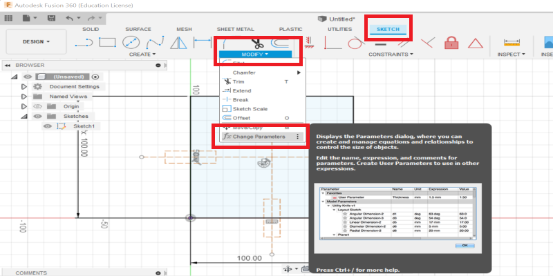
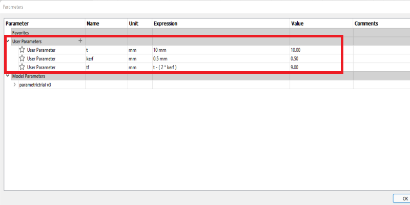
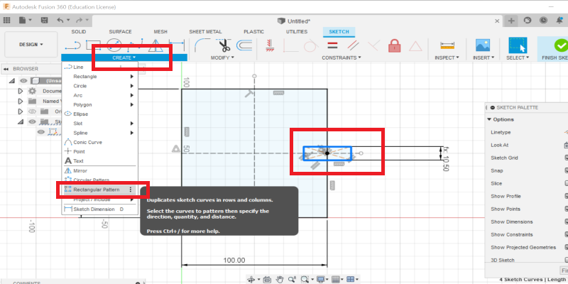
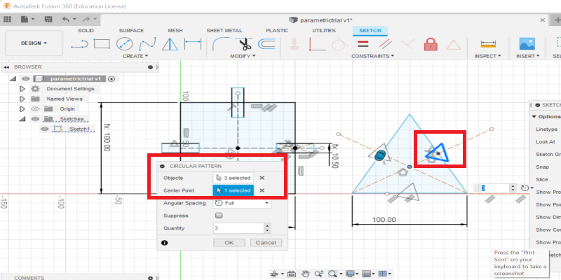
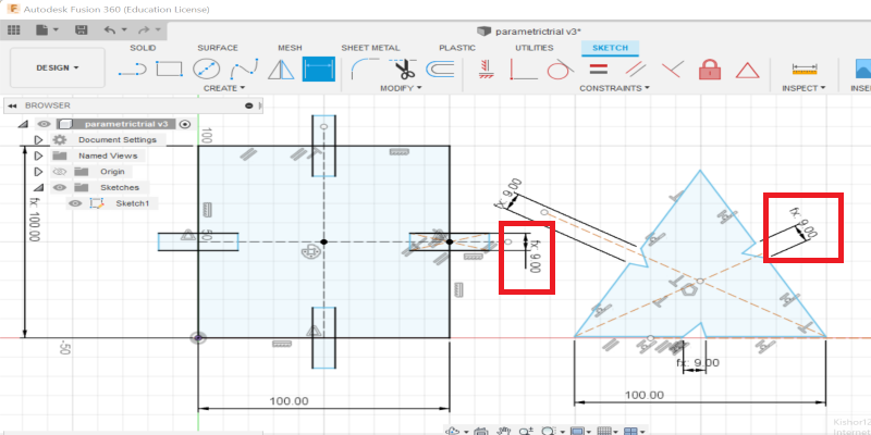
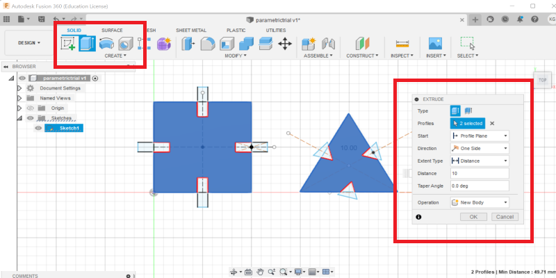
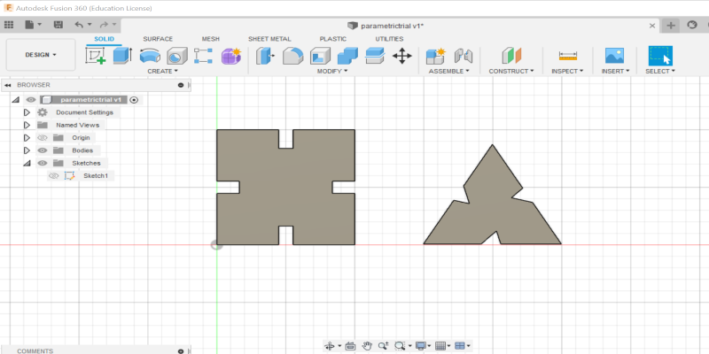
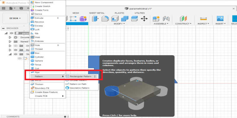
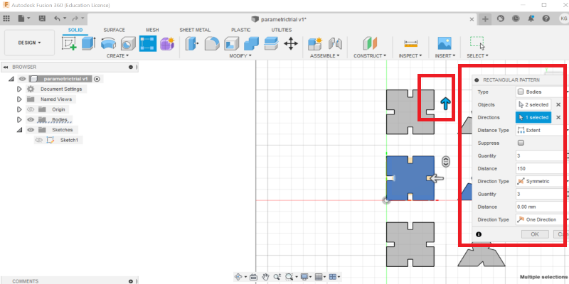
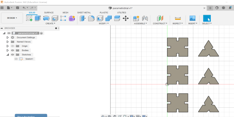
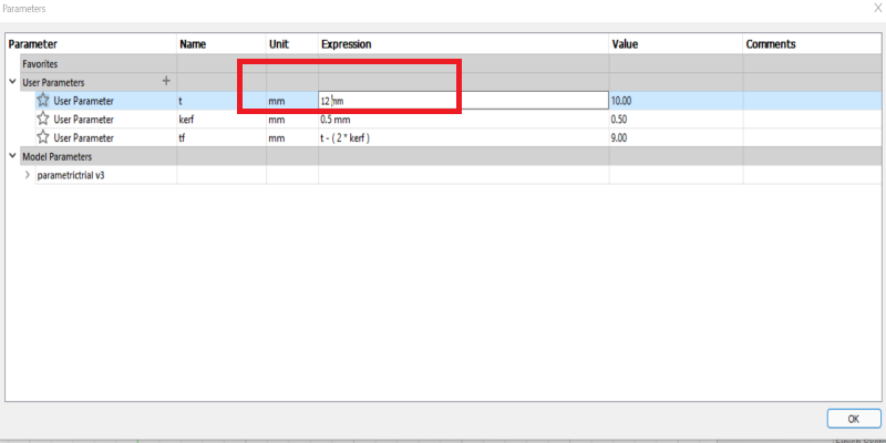
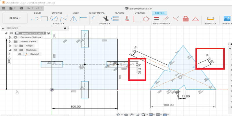
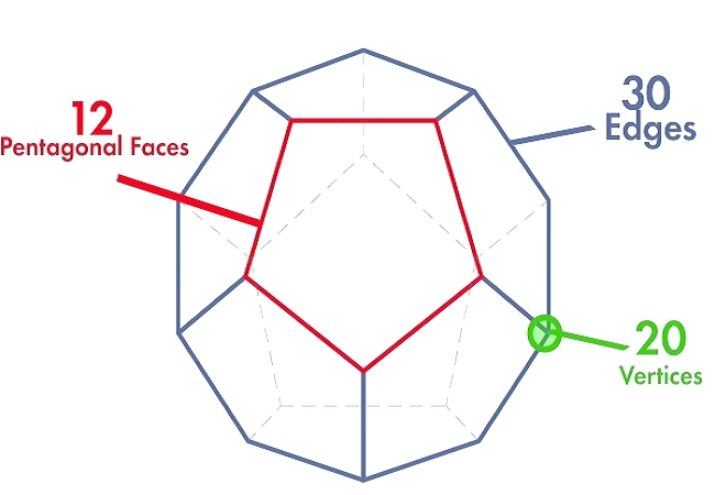
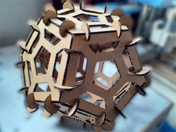
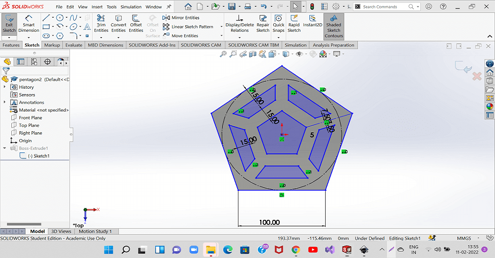
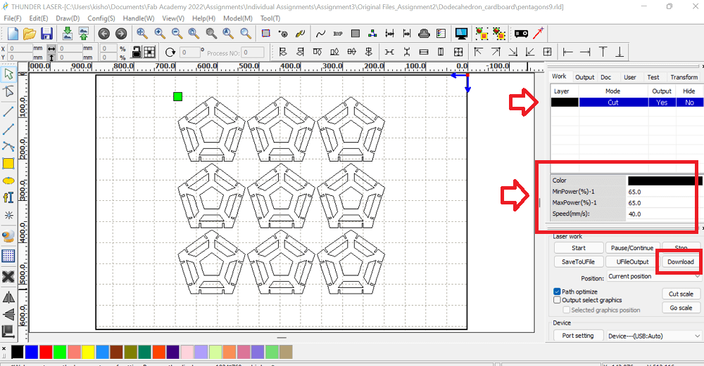
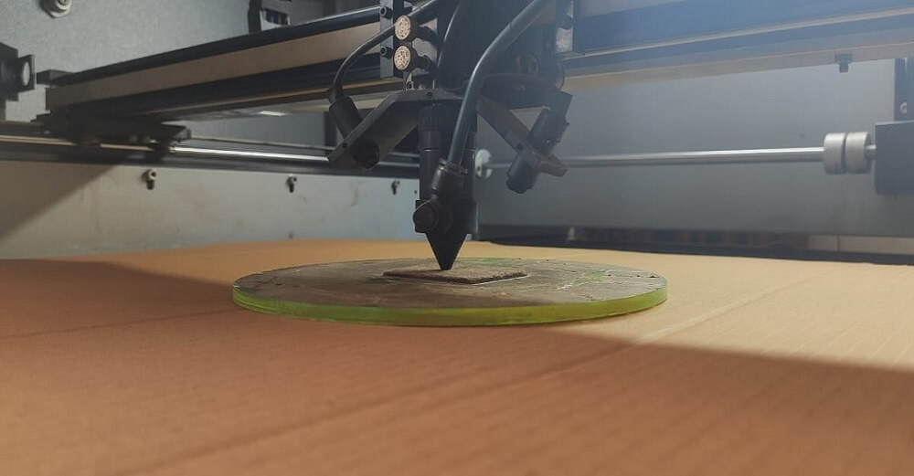
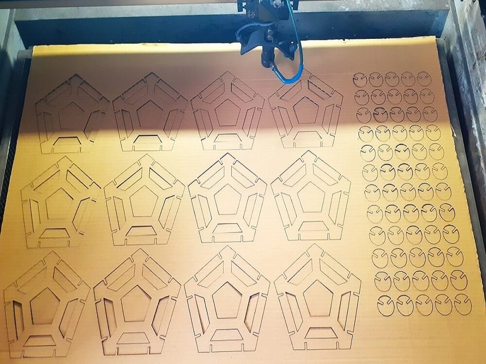
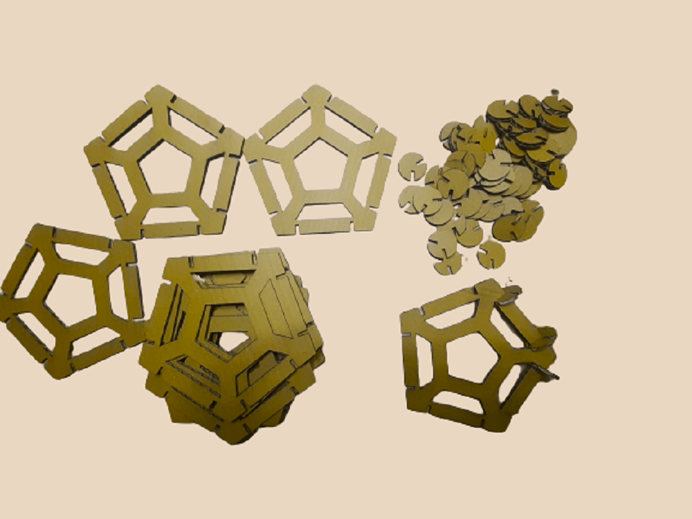
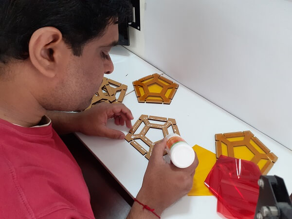
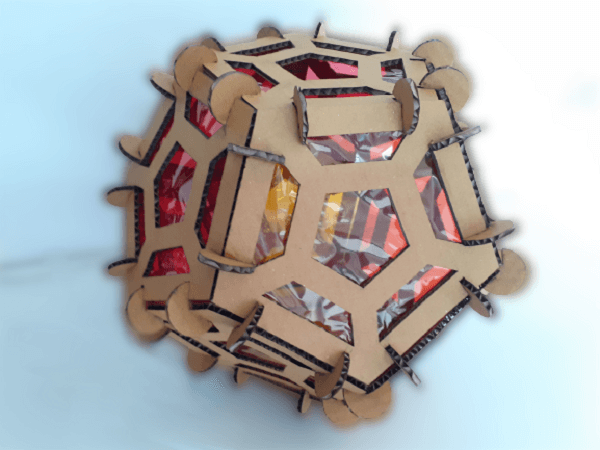
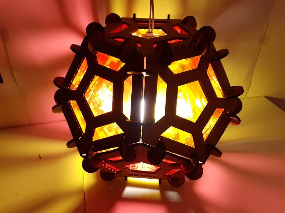
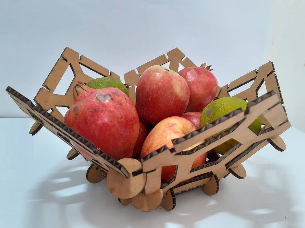
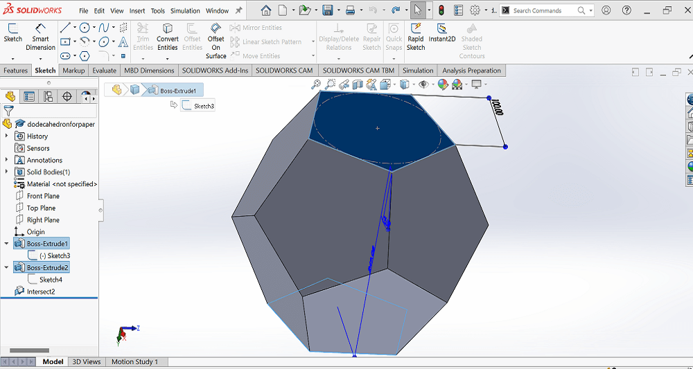
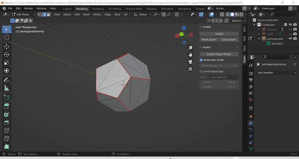
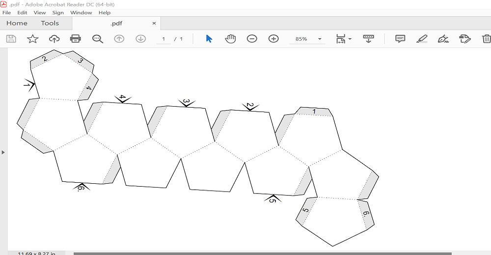
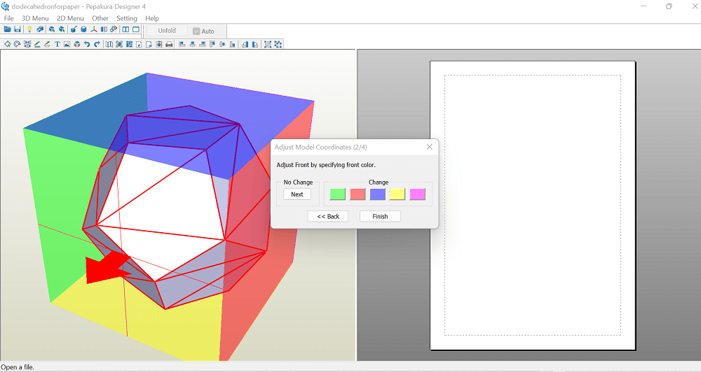
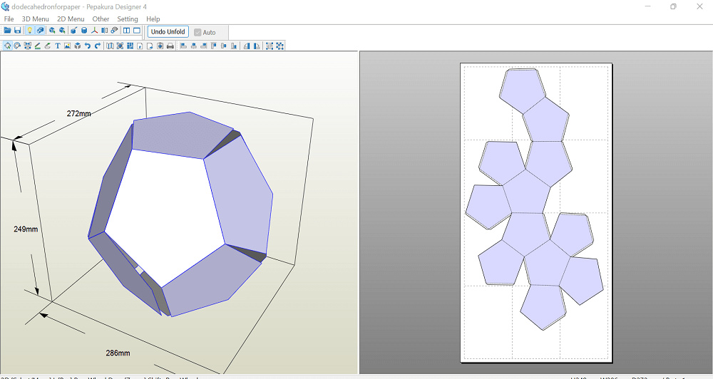
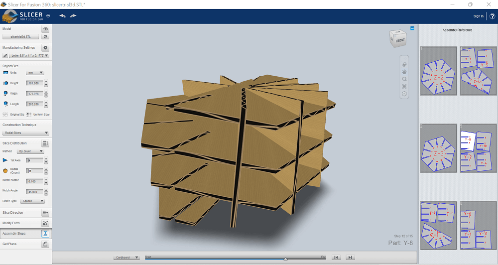
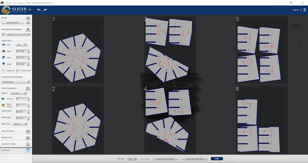
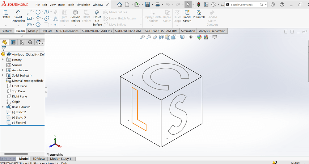
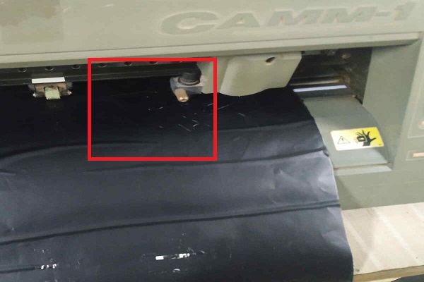
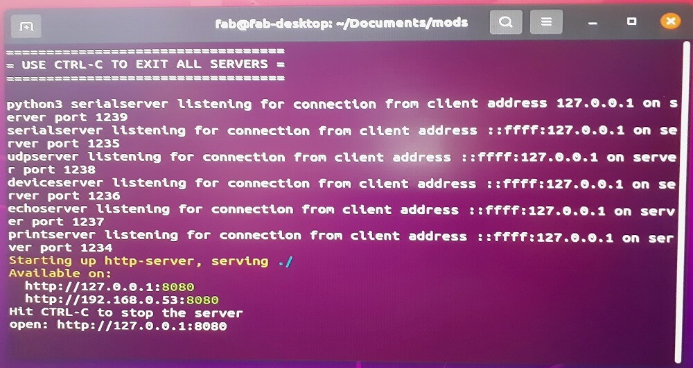
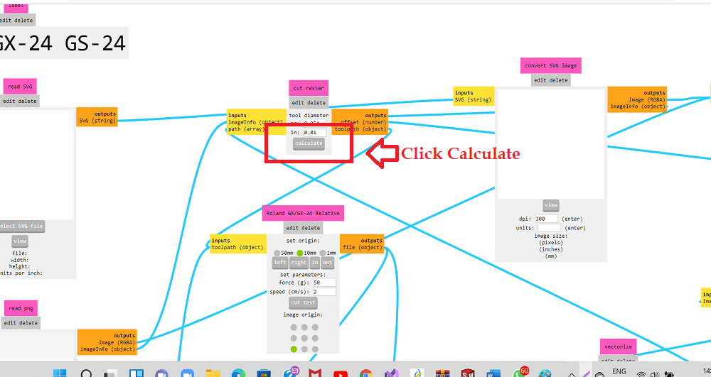
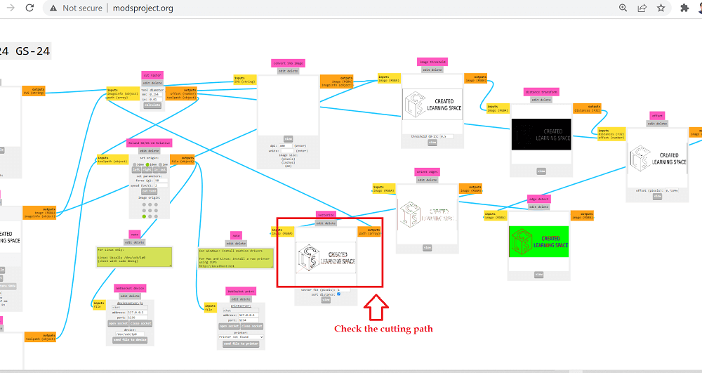
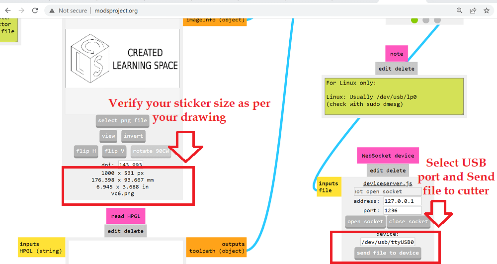
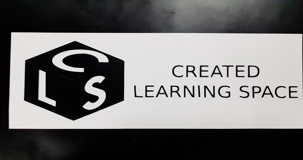
First step: I designed one square with slots on its periphery. I defined the parametric equations in Modify- change parameters menu. Added parametric equation for the slot width in the parameters table considering the material thickness and kerf. Next step: I added a triangle with slots on its periphery. I then created a circular pattern of slots on square and triangle both. I applied the parametric equation to all the slots on both square and triangle. Actully, slots created by patterning are dimension driven, so applying parametric equation only to one slot each on square and triangle is needed. In the end, extruded both the square and rectangle. The slots were intersected with main sketches before extrusion. Next step: I created a rectangular pattern of the extruded bodies by selecting the direction and quantity of pattern. The right most image in second row below shows how these objects are going to be looking like after patterning. Last step: I tried to change the material thickness in to the equation (modify equation menu) and saw all the slot width dimensions are getting changed with just changing one number in parametric equation table. It could save a lot of time in redesigning the slots. For construction kit using press fit joints, I wanted to create a Pentagonal Dodecahedron using cardboard material. I thought of using this geometrical structure as a lamp or use half of this structure as a fruit basket. It has 12 pentagonal faces attached together using press fit joints. I designed these pentagonal shapes and joints in solidworks using parametric modeling. 1. First, I created a pentagonal sketch and a part in solidworks. I Used offset and pattern commands to create the pentagon with cut through features inside it as I wanted to have them in my structure. There are 12 such pentagonal faces in dodecahedron. Two pentagons are at an angle of 116.57 deg with each other. So, it was necessary to design a press fit joint with slots made at an angle of 116.57 deg with each other. 2. Next, I used RDWorks software to send the design to laser cut machine. This software communicates with the machine using the dxf inputs and converting it to machine specific format. I then measured the cardboard sheet length and width. I cross checked that with my drawing frame. I also verified the same on laser machine by using frame button. 3. Once, everything was set-up, I switched on the laser beam and started cutting. Following are the pictures of cardboard sheet on the machine bed after cutting and hurray all the parts required for my construction kit are ready. 4. I also cut transparent color paper on laser machine. For that, I created a pentagon in solidworks but without any cut through slots on its face. I also gave it an offset of 5 mm and also matching slots. Then, I pasted these transparent papers on inside surfaces. I forgot to cut one small pentagon on the color paper to be used on top most pentagon for creating an opening for lamp wirings. I cut that using paper cutter later.I also assembled the dodecahedron half to be used as a fruit basket. My beautiful lamp and fruit baskets are ready. 5. After that, I tried using blender software for paper unfolding feature. I designed a dodecahedron in solidworks using only two sketches. Extruded these sketches in angle until they became pentagonal pyramid. Placement of two pyramids was such that their apexes pointed touched each other. Intersecting these two pentagonal pyramids created the dodecahedron part, which I wanted to export as STL file and import it in to the blender software. I used paper unfolding feature inside blender and created drawing for paper folding model. 6. Two more things I tried were Pepakura software for paper unfolding and Autodesk slicer software for laser cutting. I did not create anything out of these softwares but I wanted to learn how to use them. Following are some images for the same. A vinyl cutter is a type of computer-controlled machine. It is like a computer controls a printer nozzle or computer controls the movement of laser head in laser cutting machine. In vinyl cutter, the computer controls the movement of a sharp blade over the surface of the material. This blade is used to cut out shapes and letters from sheets of thin self-adhesive plastic (vinyl). To know more about vinyl cutter, click here to visit the company website. Below are some of the types of blades used in vinyl cutting- This machine uses a blade to cut vinyl paper. Blade is sharp so handle with care. Since, it uses a blade any possible material can be cut like normal paper, copper tape to make flexible PCB for wearables, etc. - Load the vinyl paper and set-up the machine- Roll paper, rolls as per cutting length, Lock the material load lever tight and then setting up the origin. - Use command prompt on the Ubuntu os machine to run MODS - Click Calculate button and then check cutting path - On MODS screen, verify your sticker size as per your design as shown in the picture below. - Use masking tape to weed the sticker and place it wherever you would lobve to. Here is my Sticker. In group assignment- We divided our tasks in group as per the deliverables of the group assignment. Each sub-group picked up separate material to experiment on laser cutter. Sub-groups had their own ways of designing the layout and cutting on their choice of material. So, we had diversity in terms of final outcomes of the assignment. Everybody also documented their work and contributed. In group assignment- We did not check the RDWorks setting while downloading the file to laser machine. We even did not check the preview of the engraving file on the machine control panel display. It was only when some part of the logo was engraved, we realized it. We went in to RDWorks settings and check both X and Y axis mirror buttons. It worked well then. I will use fonts with thick strokes in vinyl cutting. I will document my learning outcomes then and there itself. I will also organize my folders well. I will check press fit joints for all types of failures. - I learned the importance of safety precautions while operating laser machine. I also learned what kind of materials are hazardous to cut on the laser cutter. Click here to download all CAD files.Parametric modeling in Fusion 360
Construction Kit using Parametric modeling in Solidworks
Preparations
I used parametric equations in solidworks to define the slot width based on the cardboard thickness (3 mm) and kerf (o.15mm). I generated the dxf files for my design.
I also set up laser beam focus by adjusting the Z axis using the standard template created. I then cut a few sample press fit joints to try on the cardboard sheet. I chose the parameters for cutting on laser that was used for the best press fit joint before I cut 60 of such pieces for an entire structure.
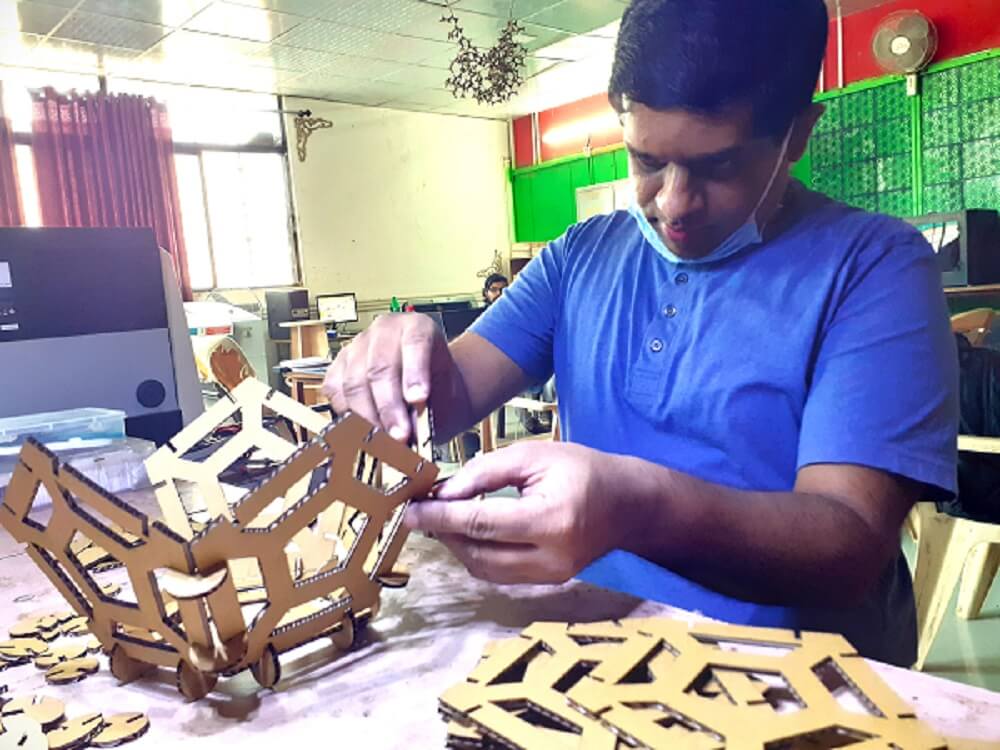
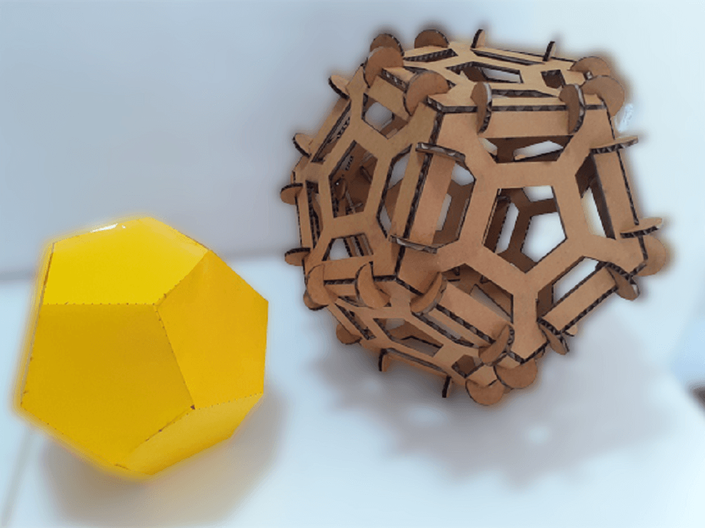
I assembled the pentagons carefully using the press fit joints. Because of the correct kerf value and angle between slots was designed correctly, the dodecahedron structure was assembled perfectly. I had some challenges fitting one pentagon between the two pentagons. I had to make the joints loose and then again adjust once the pentagon is aligned in to all the slots around. Finally my pentagonal dodecahedron is ready.
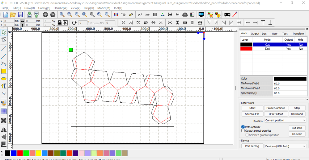
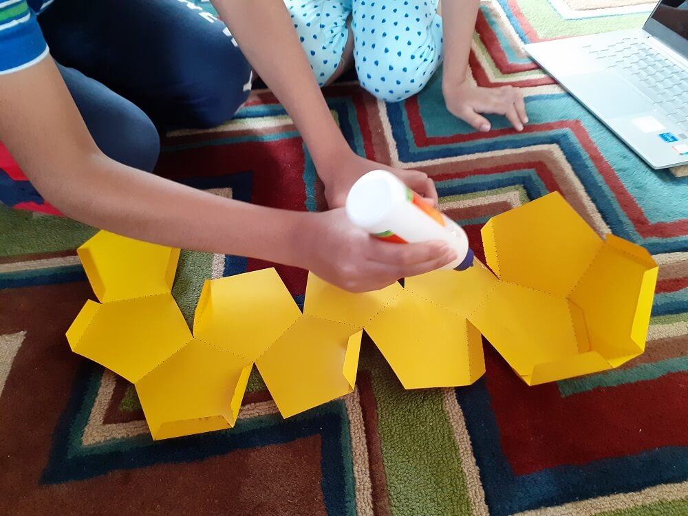
Then, used inkscape to create dxf file from the pdf drawing. Imported this dxf into the RDWorks software to create cut and dot paths. Finally, I could cut this folding model on craft paper using the laser cutter. My children folded the paper as per the print and the paper dodecahedron is ready. This was created in a reduced scale of my original cardboard sheet.
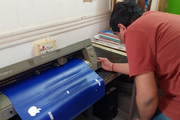
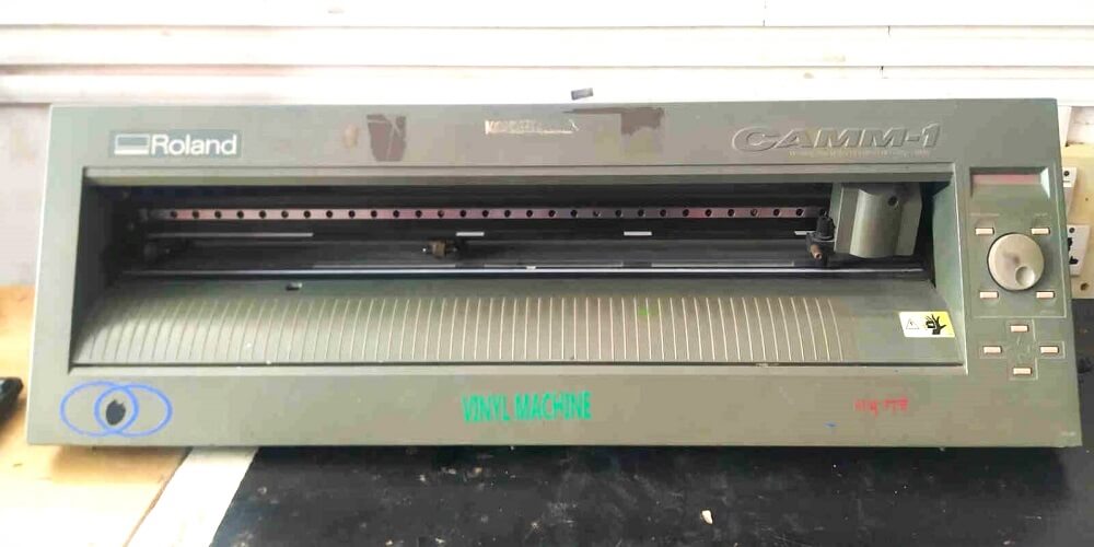
Vinyl Cutter
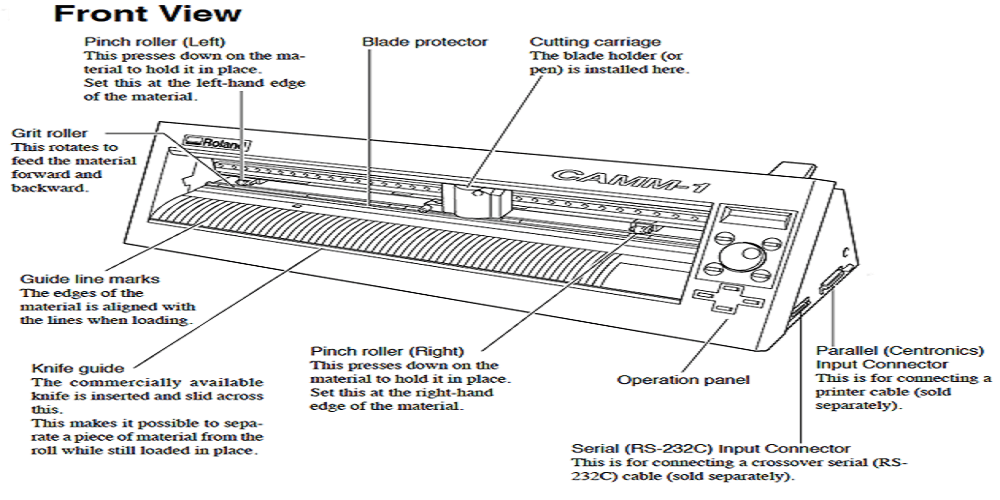
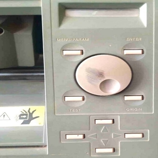
The CX-12/24 is exceptionally easy to use and incorporates advanced features previously available only on Rolands PRO series vinyl cutters. These features are:
- One piece front panel
- JOG dial eliminating dipswitches
- Push button replace membrane switches
- Relocated material load lever
- Larger, single-action pinch roller assembly
- Cutter knife groove on front apron for easier manual cutting
To learn more how to operate this vinyl cutter machine Click here.
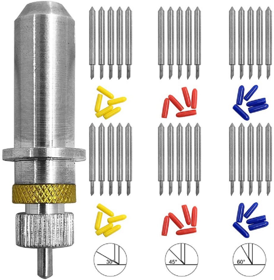
Vinyl Cutter- Blades and their types
- 30 deg blade is used for very thin material.
- 45 deg blade is used for general vinyl cutter.
- 60 deg blade is suit for thick material like copper sheet, mirror sheet, sand blast regist sheet.
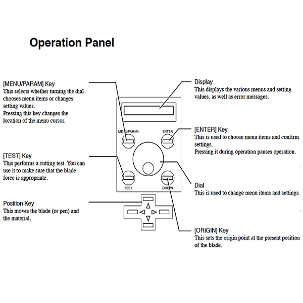
Vinyl Cutter- Operational Instructions
Following are the steps to operate CX-12/24 vinyl cutter:
- First, create any design you want to print as a logo or circuit, etc. in CAD software.
- Export design sketch in png or svg format. Your vinyl cutter files must contain only vectors with lines only and no fill. All vectors must be contained within the bounds of the document canvas.

- Specifications we used for cutting are- 45 deg cutting angle blade, force 130 gf and speed of 1 cm/s
- Before you start anything, first find out exactly where on the vinyl paper you want to print the design and accordingly set the origin.
- Open your design png or svg file in MODS. Click Read SVG or Read PNG button
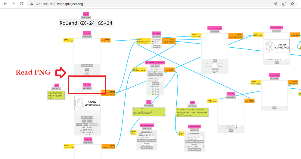
- Select socket, choose the USB the port and hit send the file to device button provided you have set-up your vinyl cutter machine as per earlier steps.
Click here to go back to the top
What went well
In laser cutting individual assignment- I tried parametric modeling in Fusion 360 and Solidworks both. Use of different commands like offset, pattern, creating line, dimensions, etc. helped to create models quickly. I could assemble my construction kit immediately after the parts were cut. I tried doing different structures. In some extra time I had, learned Blender, Pepakura and slicer software. I was also able to cut the chart paper and thin color paper on laser machine with precision.
In vinyl cutting individual assignment- I learned to set-up vinyl machine myself and use MODS project. I later learned to use various tools to effectively weed the sticker.What went wrong
In laser cutting individual assignment- The slots on press fit joints are at an angle of 116.57 deg with each other. Carboard material being 3 mm thick, a few of the joints got bent at the slots while pressing. It would have not been a problem with plywood or MDF. Also, I did not cut slots on the color paper that I wanted to put inside the lamp, I cut them later.
In vinyl cutting individual assignment- Tried to design a complicated logo and it took some extra time. Also, I wanted to have multi-colored logo, so I decided to cut different parts of my logo on different vinyl paper. However, it was quite time consuming. So, I switched to single colored logo. Also, while weeding the sticker, I realized that the letters stroke was too think to be able to peel them well. Sometimes, some of the letters got stuck or were not peeling off properly.What I would do differently
Learning Outcomes
- I can now do parametric modeling in FreeCAD, Fusion 360 and Solidworks and its importance in laser cutting
- I learned how to create drawings using letters in solidworks, as the quality of dxf output from Solidworks is much better than any vector 2D design software
- I got to operate the laser and vinyl cutting machines hands on
- I learned how to use time effectively while working on group assignment and also on individual assignmentDownload Original CAD Files