Group Assignment #1: Computer Controlled Cutting
This week, we worked on Laser cutting and scanning group assignment. We divided ourselves in 3 groups and conducted various trials on laser cutting machine.
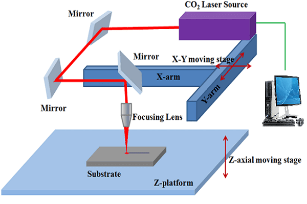
What is Laser cutting: Laser cutting is a technology that uses a laser to cut materials, and is typically used for industrial manufacturing applications, but is also being used by schools, small businesses, and hobbyists. Laser cutting works by directing the output of a high-power laser most commonly through optics. The laser optics and CNC (computer numerical control) are used to direct the material and the laser beam generated. It is necessary to know the principle and schematic of a laser cutting machine (see the image below), details of the laser cutting machine, machine specification and precautions to be taken while operating the machine, important parameters of laser cutting operation like speed, power and every laser cutting operation has a kerf value associated with it. Before we go any further, we need to know more abour kerf:
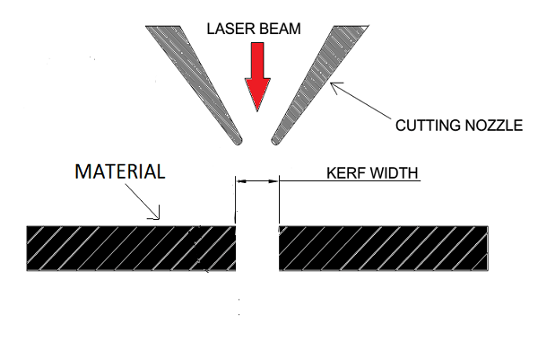
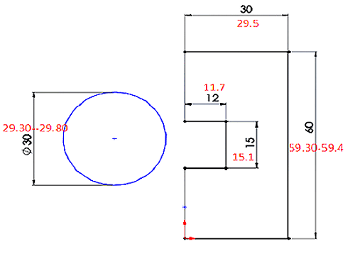
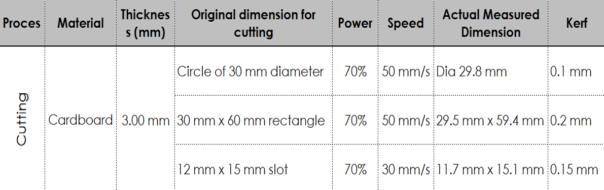
What is Kerf in laser cutting: When a laser cuts through a piece of material, the lasers own width displaces a little extra material than is specified in the original design. The amount of material that is burned away is known as the kerf in laser cutting (see the image below). The size of the kerf depends on the laser being used and the material being cut. It not only changes as per each material, but it changes based on speed, beam power, cutting geometry, assist gas and a few other factors.
Schematic of a Laser cutting and Kerf
 |
 |
Objectives of this Group Assignment:
- Understand the Laser cutting machine, its specifications
- Understand how to operate the machine
- Learn safety precautions while operating the Laser Cutting Machine
- To find out the optimum speed and power values along with calculating the Kerf value for various materials
These values are now helpful for us while working on laser cutting for our individual assignments and project. Once we have optimum speed, power and Kerf values, we can modify our CAD models parametrically based on these values.
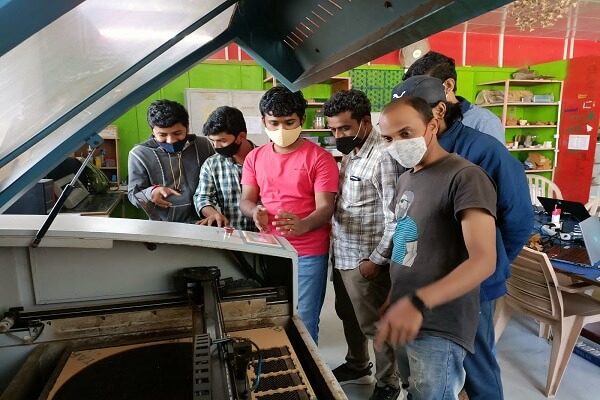
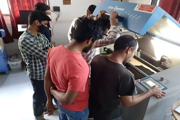
We have documented how we calculated kerf values for different materials in detail in subsequent sections of the assignment below. Following are some of the glimpes of our team work.
 |
 |
Understand the laser cutter
Laser Cutting is arguably one of the most useful manufacturing process that Fablabs possess. It is capable of engraving or cutting various different types of materials. They are available in different wavelength, power levels and bed sizes for different applications. The ones that are seen most often commercially are- Fiber Laser, CO2 Laser, Diode Laser. These cutting Machine are versatile and have various applications in signage, art & craft, gift, shoes, toys, garments, model cutting, papers & packaging, wood & MDF cutting industry, interior, decorators and many more.
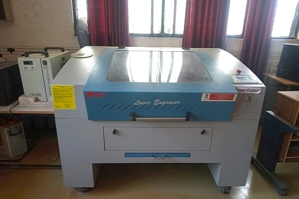
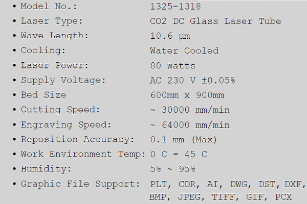
The Vigyan Ashram Fablab owns an 80-watt CO2 Laser Cutting Machine by SIL. Here is a picture of the machine along with its specifications:
 |
 |
For more information about this laser cutter, please visit this page: SIL CO2 Laser Cutter
Precautions while operating the Laser Cutting Machine
- Do not put your hand between the lenses when the laser beam in ON
- While the machine is ON during cutting or engraving, keep the door always shut closed
- After cutting or engraving is done, do not open the door immediately. Let all the smoke vent out through the exhaust fan. Inhaling this smoke is hazardous to our health
- Do not cut/engrave certain material like Polycarbonate (PC, Lexan sheets), any material containing chlorine, PVC (Sintra), Vinyl, Glass, Fiberglass, Carbon fiber, etc. as they contain certain compounds that are hazardous
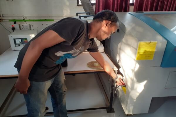
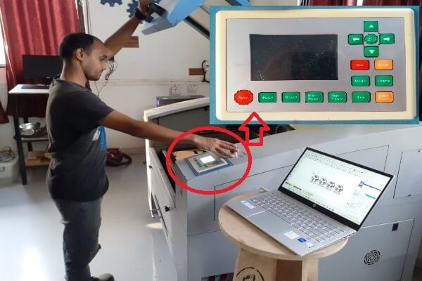
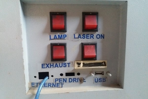
Turning the Laser on
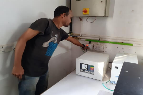
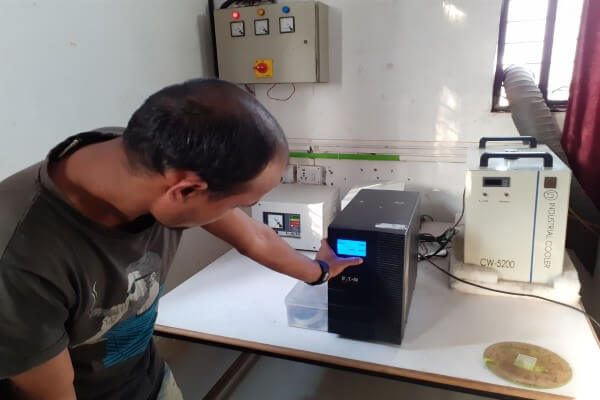
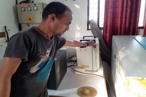
Since the Vigyan ashram is situated in a remote rural area, there are frequent power cuts and voltage fluctuations. This is a major issue that could harm a laser cutter. So, in order to ensure that the machine stays safe, there are a number of peripherals that are used to reduce the fluctuations. Therefore to turn the machine on, there are certain steps that one must to go through. Here are the things that need to be done to make the machines work:
1. First, switch ON the servo voltage stabilizer: A servo voltage stabilizer is a closed-loop control mechanism which serves to maintain balanced 3 or single-phase voltage output despite fluctuations at the input owing to unbalanced conditions (Source: Elprocus.com)
2. Next, switch ON the isolation transformer: An isolation transformer is a transformer used to transfer electrical power from a source of alternating current (AC) power to some equipment or device while isolating the powered device from the power source, usually for safety reasons. Isolation transformers provide galvanic isolation; no conductive path is present between source and load. This isolation is used to protect against electric shock, to suppress electrical noise in sensitive devices, or to transfer power between two circuits which must not be connected. A transformer sold for isolation is often built with special insulation between primary and secondary, and is specified to withstand a high voltage between windings (Source: Wikipedia)
 |
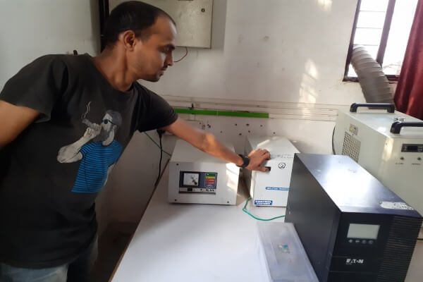 |
3. Switch ON the inverter: This component makes the machine run for x time after the main power has been disconnected. Helps to turn off the machine in a controlled manner in the event of a power cut. To turn it on, the button has to be pressed until the display shows that the load is connected.
4. Next, switch ON the Chiller/Cooler: This component is used to cool the CO2 laser tube, and needs to be filled with de-ionised water, or atleast RO purified water. Pressing the red button turns it on. We need to stop the operation if chiller gives a high temperature warning buzzer.
 |
 |
 |
 |
 |
 |
What we did
As mentioned earlier, we divided ourselves in 3 groups. One group worked on carboard, second one worked on the acrylic and third group worked on plywood and MDF sheets. Each group made their drawings for cutting and scanning and experimented with different settings of speed and beam power.
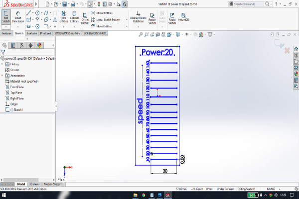
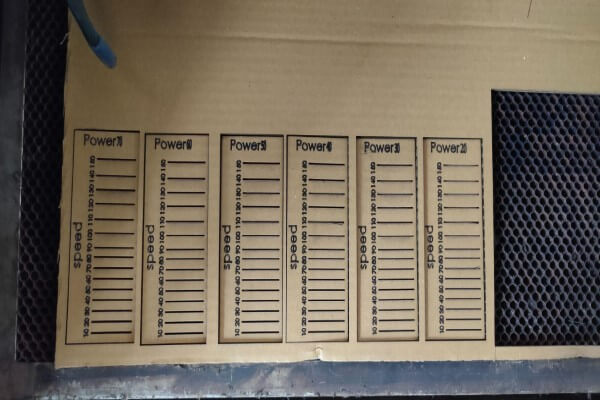
1. Carboard cutting
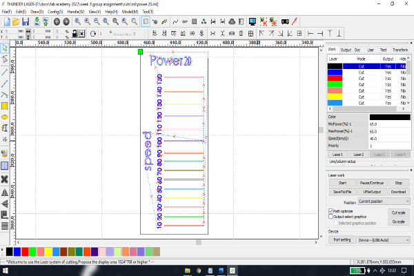
Preparations: Selected a 3 mm thick cardboard sheet. To find out how the machine would work with different speed and power settings while cutting cardboard, the team designed a sketch in solidworks. Generated a dxf file, which was imported in a machine software called RDWorks. This software is used to send the inputs to the laser cutting machine. Below are the snapshot of the dxf file and layout in RDWorks. Then, we assigned different colors to the cutting paths in RDWorks where each color represents different speed and power.
 |
 |
Results and conclusion:
Below are the pictures of the carboard sheets that we used for cutting operation. The right most image is the backside view of the sheet to check for, which setting, the cuts are through. Looking at the results, we concluded that for a 3 mm cardboard sheet, if we want to cut with a speed of 50 mm/s, we will need to use 70% of the power. If we want to cut with 40 mm/s speed, we will need 50% power. We can use 40% power but the part is not cut through, we will need to push the piece to take it apart from the sheet. It is recommended to increase the power or decrease the speed appropriately to get results. Also, do a small test cut on the material always to check the results of the defined power and speed.
 |
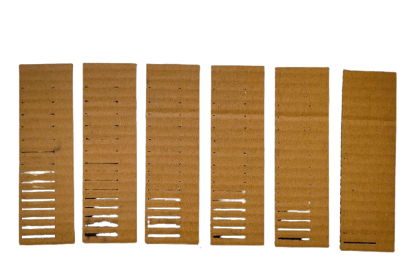 |
Then we calculated the kerf for 3 mm cardboard sheet by measuring the actual dimensions and comparing them to the designed dimensions. The difference between these two dimensions gave us the kerf value.
 |
 |
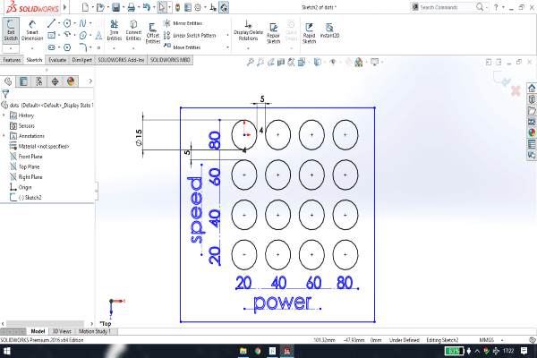
2. Carboard- Marking Dots
Preparations: Again used a 3 mm thick cardboard sheet. To find out how the machine would work in marking dots with different speed and power settings, the team designed a sketch in solidworks. Generated a dxf file, which was imported in RDWorks. Below are the snapshot of the dxf file and layout in RDWorks. Then, we assigned different colors to the cutting paths in RDWorks to assign different speed and power.
 |
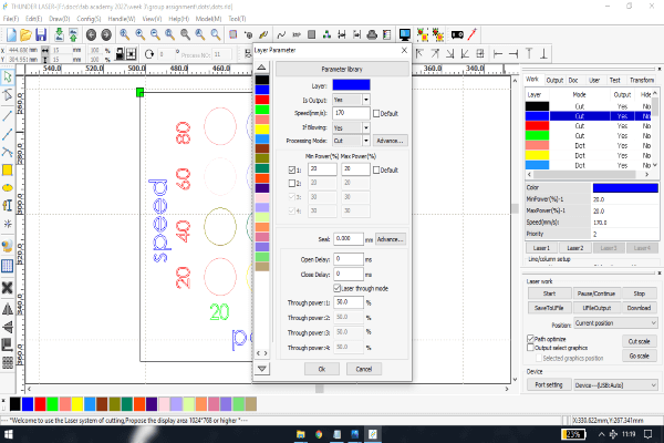 |
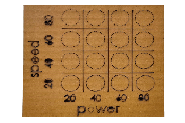
Results and conclusion:
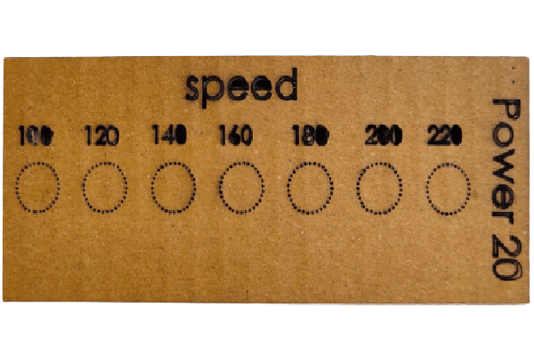
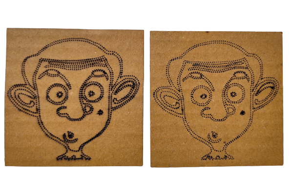
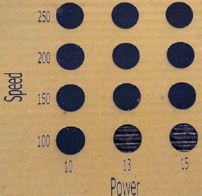
Below are the pictures of the carboard sheets that we used for creating dots operation. Looking at the results, we saw that for a 3 mm cardboard sheet, the machine was able to mark the dots properly with 80 mm/s speed and 20% power. The right most image is of the experiment to see how fast we can cut the cardboard with 20% power, we made another file and tested it. It was concluded that the laser cutting machine was easily able to cut dots with 220 mm/s speed and just 20% power. At the end, we traced an image from inkscape and cut that with dot pattern in the machine. However we also used 200 mm/s speed and 20% power.
 |
 |
 |
3. Carboard scanning
Preparations: We used a 3 mm thick cardboard sheet. To find out how the machine would work in scanning/engraving with different speed and power settings, the team used the same dxf file that was used in marking dots, modified it to edit the text for the settings. It was then imported in RDWorks.
Results and conclusion:
Below is the snapshot of final part with engraving done. Looking at the results, we concluded that for a 3 mm cardboard sheet, the machine was able to engrave properly with 200 - 250 mm/s speed and 10% - 13% power. As we increased the power and reduced the speed, it resulted in deep engraving with not so good quality of engraving.
 |
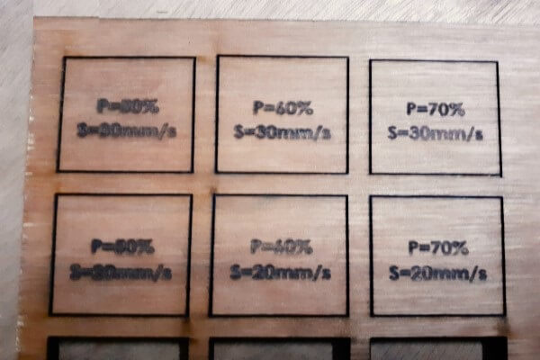
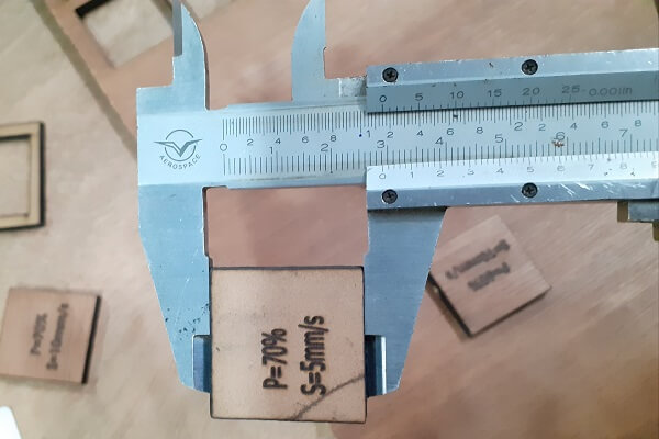
4. Plywood and MDF cutting
Preparations: Selected a 4 mm thick plywood and MDF sheets. To find out how the machine would work with different speed and power settings for both plywood and MDF, the team designed a sketch in solidworks. Generated a dxf file, which was imported in RDWorks. Below are the snapshot of the sketch and dxf file. Then, we assigned different colors to the cutting paths in RDWorks where each color represents different speed and power.
 |
 |
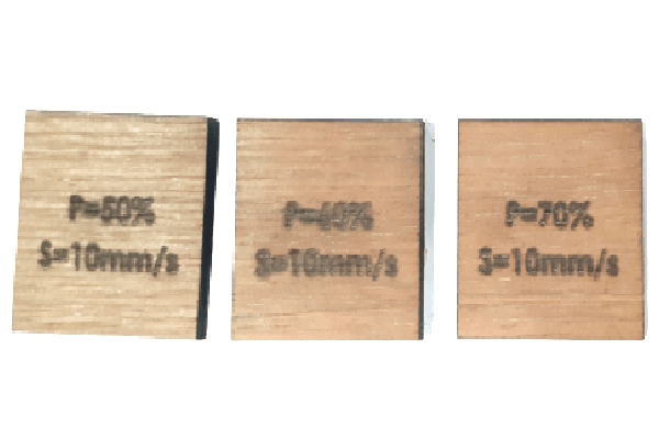
Results and conclusion:
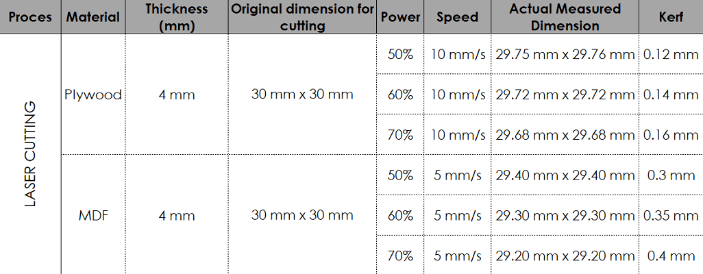
Below are the pictures of the plywood and MDF sheets that we used for cutting operation. The right most images in both the rows of pictures below show the through cut pieces. The left most images in both the rows show that the machine was not able to cut through the sheets at those settings. Looking at the results, we concluded that for a 4 mm plywood sheet, if we want to cut with a speed of 10 mm/s, we will need to use 50% - 70% of the power. If we want to cut a 4 mm MDF sheet, we need to reduce the speed to 5 mm/s with 50% - 70% of the power for material to cut through. We can not cut plywood at a speed of 20 mm/s and above. Similarly, MDF can not be cut at 10 mm/s and above.
 |
 |
 |
 |
Then we calculated the kerf for 4 mm plywood and MDF sheets by measuring the actual dimensions and comparing them to the designed dimensions. The difference between these two dimensions gave us the kerf value. The more power we use, more will be the kerf value.
 |
 |
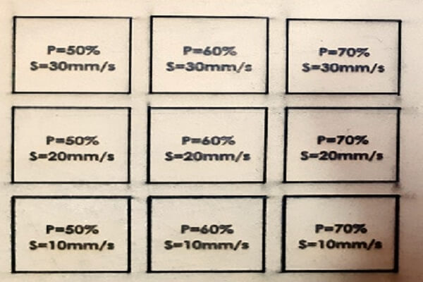
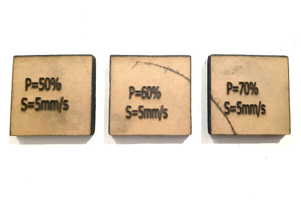
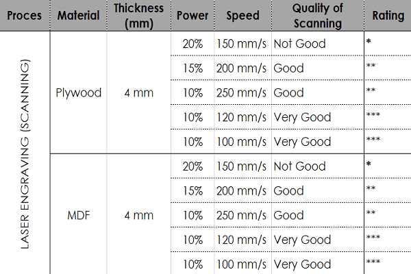
5. Plywood and MDF scanning
Preparations: We used 3 mm thick plywood and MDF sheets. To find out how the machine would work in scanning/engraving with different speed and power settings, the team created one dxf file in Inkscape for plywood and MDF both. It was then imported in RDWorks to apply speed and power settings. Below are the snapshot of the dxf file and layout in RDWorks.
 |
 |
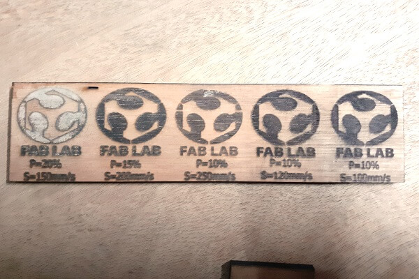
Results and conclusion:
Below are the snapshots of plywood and MDF sheets with engraving done. Looking at the results, we concluded that for 4 mm plywood and MDF sheets, the machine was able to engrave with a very good quality at 100 - 120 mm/s speed and 10% power. As we increased the power and reduced the speed, it resulted in deep engraving with poor quality of engraving. Similarly, with low power and high speed also, the quality of engraving was good, it was not that bad.
 |
 |
 |
6. Acrylic cutting and scanning
Preparations: Selected a 4.4 mm thick acrylic sheet. To find out how the machine would work with different speed and power settings for acrylic material, the team designed a sketch in solidworks. Generated a dxf file, which was imported in RDWorks. Then, we assigned different colors to the cutting paths in RDWorks where each color represents different speed and power. Below are the snapshot of the actual parts cut.
 |
 |
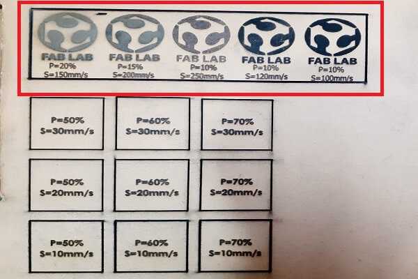
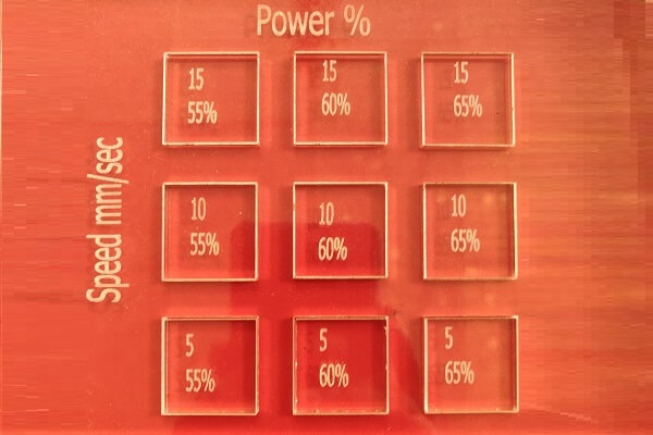
Results and conclusion:
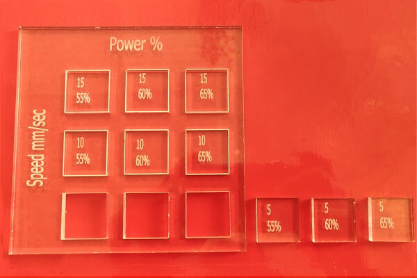
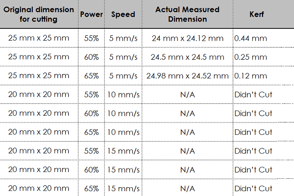
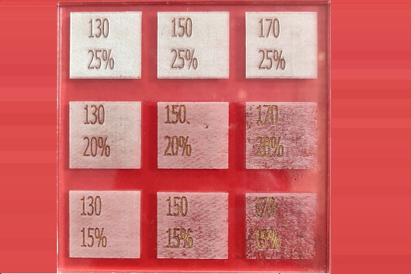
We then calculated the optimum speed and power settings for 4.4 mm thick acrylic sheet. The left most image below show that the machine was not able to cut through the sheets at a speed of 10 mm/s even at a power of 65%. If we had increased the power above 65%, the acrylic sheet would have started melting. Looking at the results, we concluded that for a 4.4 mm acrylic sheet, if we want to cut with a speed of 5 mm/s, we will need to use 55% - 65% of the power. After that, we also calculated kerf values. The right most image below shows the engraving done on acrylic sheet. We were able to engrave with very good quality for the same acrylic sheet at a setting of 25% power and speed of 130 - 150 mm/s.
 |
 |
Learning outcomes
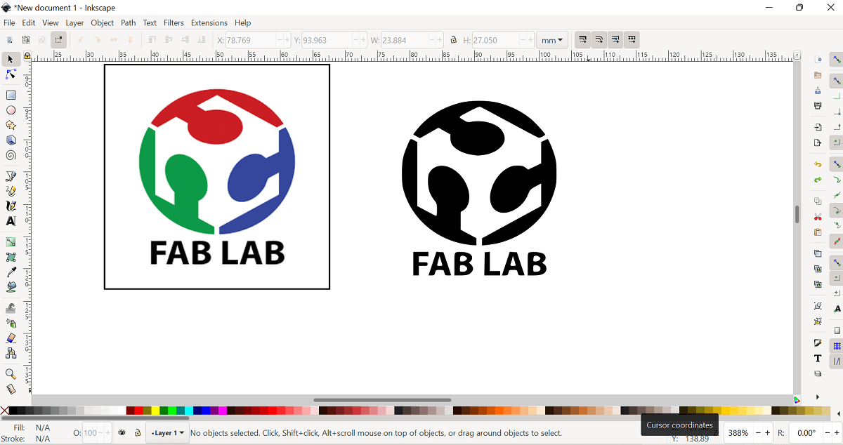
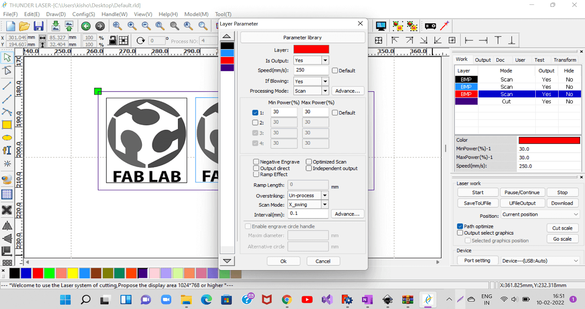
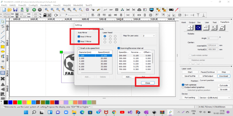
While importing the dxf file in RDWorks softwaee, we did not pay attention to the orientation of the drawing downloaded in to the machine. It was mirror image of original sketch along Y axis. When we started the engraving operation, we realized that only when the engraving operation started. We then went in to the settings of RDWorks and checked the mirror image settings and applied it to both X and Y axis. It was then, it engraved the image as is. Below are the snapshot of the actual part and settings we did in RDWorks.
 |
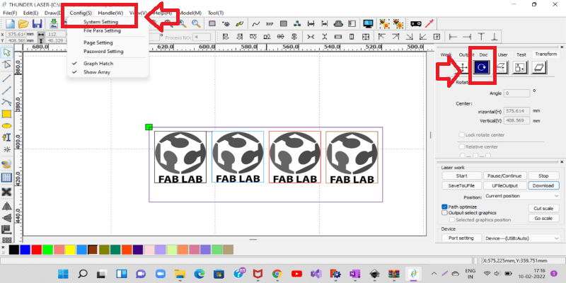 |
 |