Group Assignment #6: Embedded Programming
This assignment is about documenting what we learned in Embedded programming week that includes understanding the data sheets of microcontrollers, compare the performance and development workflows for other architectures. We used ESP32 board, which is from Xtensa family of microcontrollers. We used micropython to program the ESP32 through Thonny IDE to blink an inbuilt as well as external LED attached to this board.
Objectives of the Group Assignment:
- Understanding the data sheets of microcontrollers
- Compare the performance and development workflows for other architectures
 |
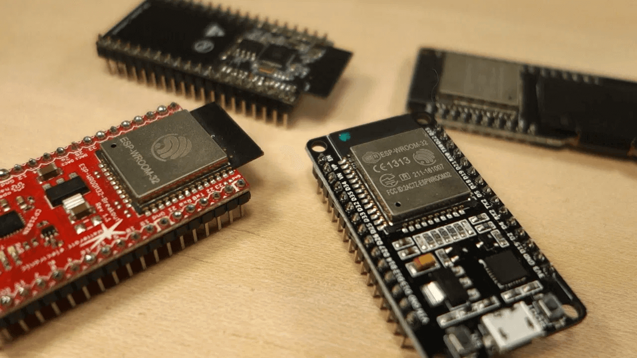 |
ESP32 Development Board
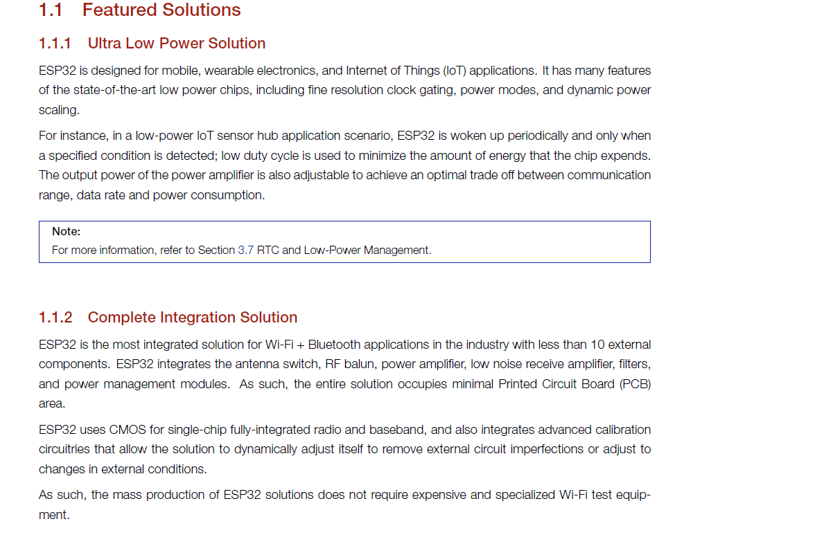
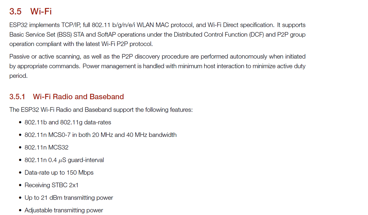
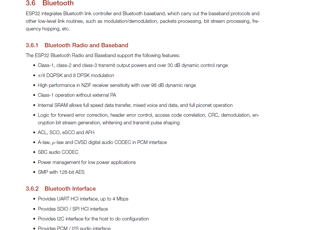
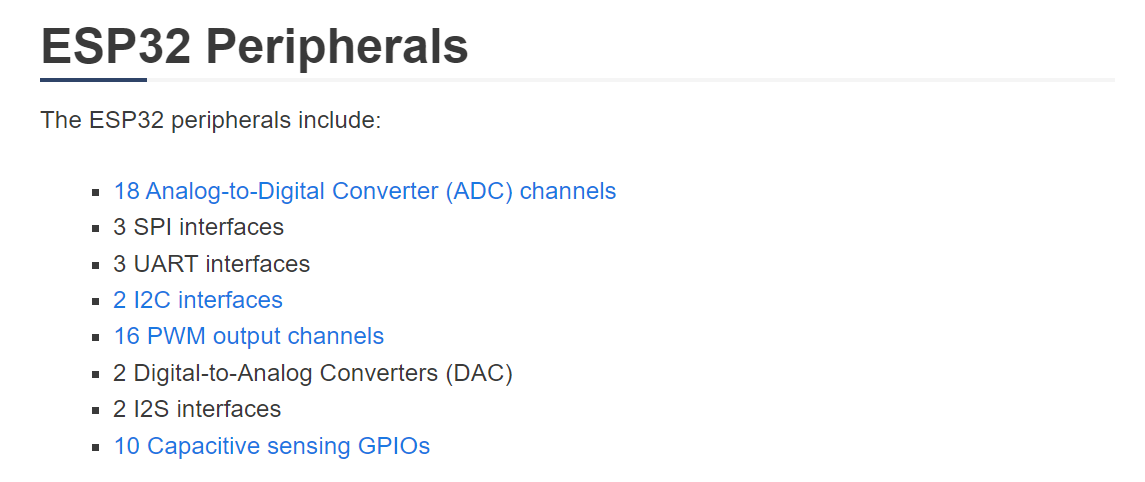
For this group assignment, we worked on understanding ESP32 development board, it's datasheet and then we did embedded programming on this board. If you are familiar with the ESP8266, the ESP32 is its successor. The ESP32 is loaded with lots of new features. The most relevant: it combines WiFi and Bluetooth wireless capabilities and it's dual core. Following are the specifications of ESP32 chip and ESP32 Development board
 |
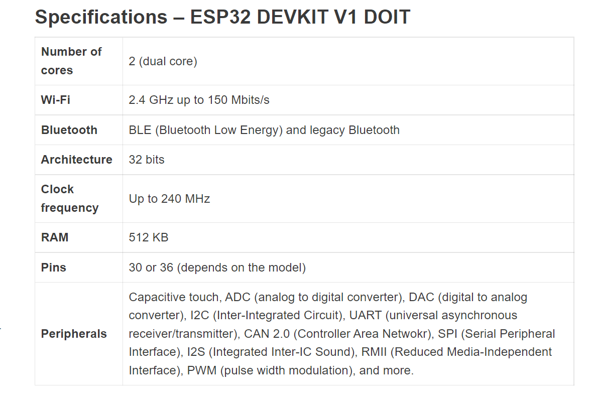 |
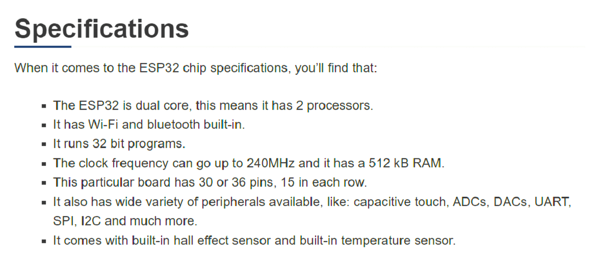
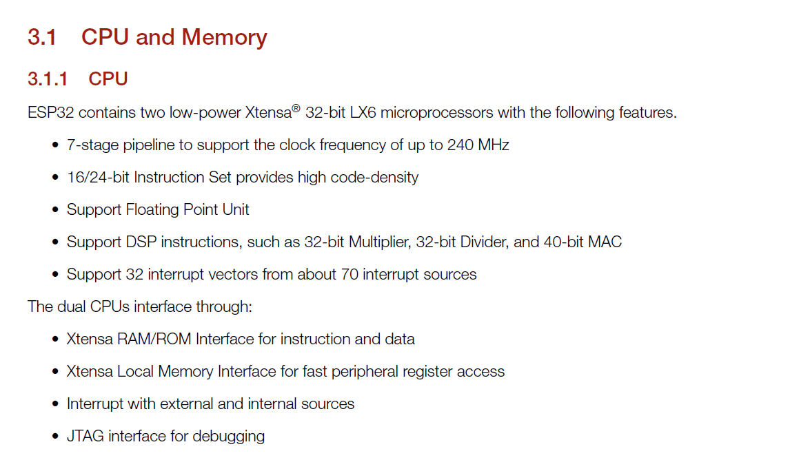
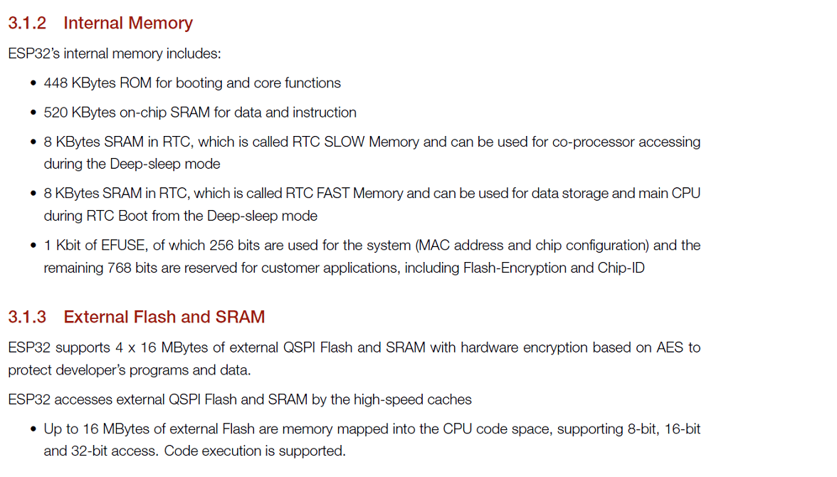
ESP32 Datasheet
A data sheet, data-sheet, or spec sheet is a document that summarizes the performance and other characteristics of a product, machine, component (e.g., an electronic component), material, subsystem (e.g., a power supply), or software in sufficient detail that allows a buyer to understand what the product is and a design engineer to understand the role of the component in the overall system. Typically, a data sheet is created by the manufacturer and begins with an introductory page describing the rest of the document, followed by listings of specific characteristics, with further information on the connectivity of the devices. In cases where there is relevant source code to include, it is usually attached near the end of the document or separated into another file. Data sheets are created, stored, and distributed via product information management or product data management systems. Click here to read more. Following is our understanding after datasheeet of ESP32 microcontroller.
 |
 |
 |
 |
 |
 |
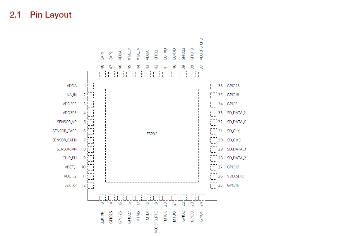
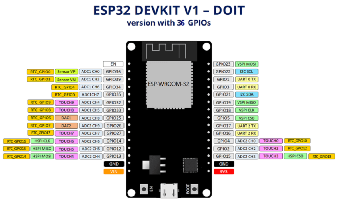
ESP32 Pinout Guide
 |
The ADC (analog to digital converter) and DAC (digital to analog converter) features are assigned to specific static pins. However, with the ESP32 you can decide which pins are UART, I2C, or SPI - you just need to set that on the code. This is possible due to the ESP32 chip's multiplexing feature that allows to assign multiple functions to the same pin. If you don't set them on the code, the pins will be used as default - as shown in the figure below (the pin location can change depending on the manufacturer).
 |
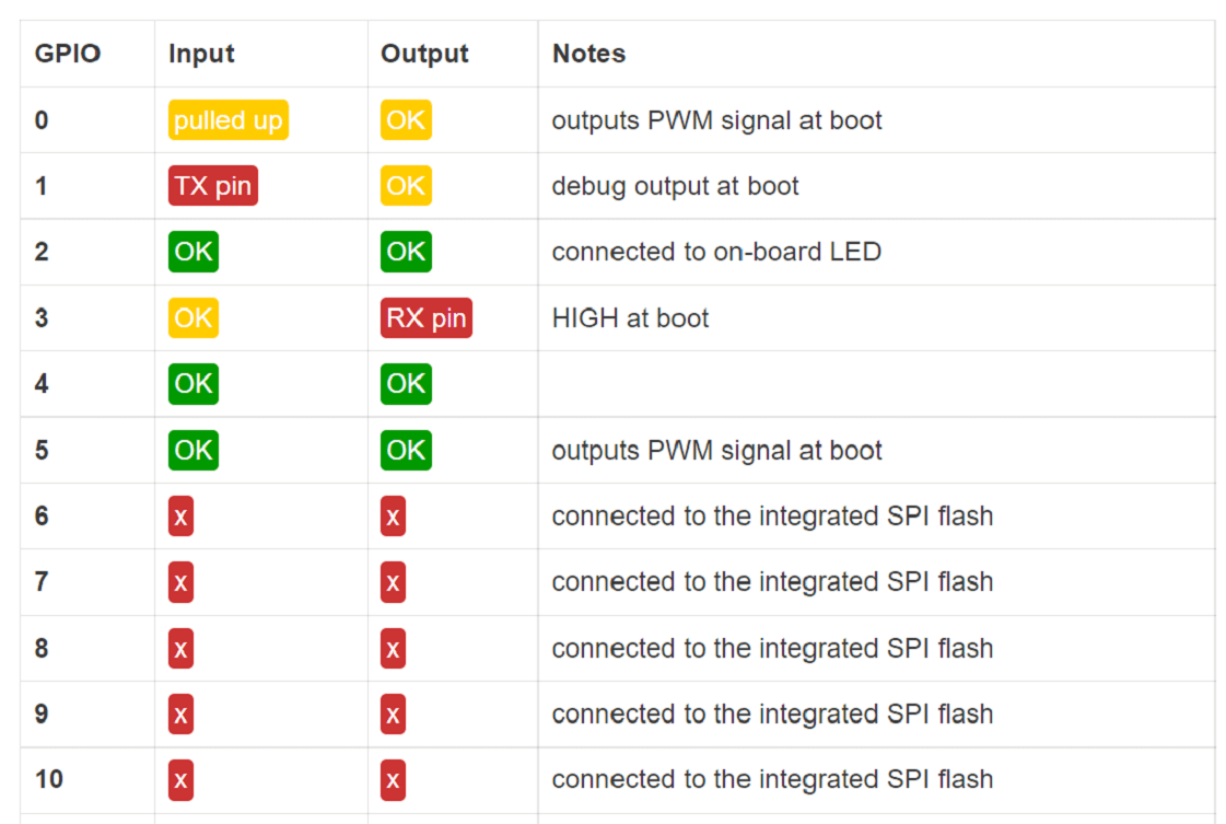
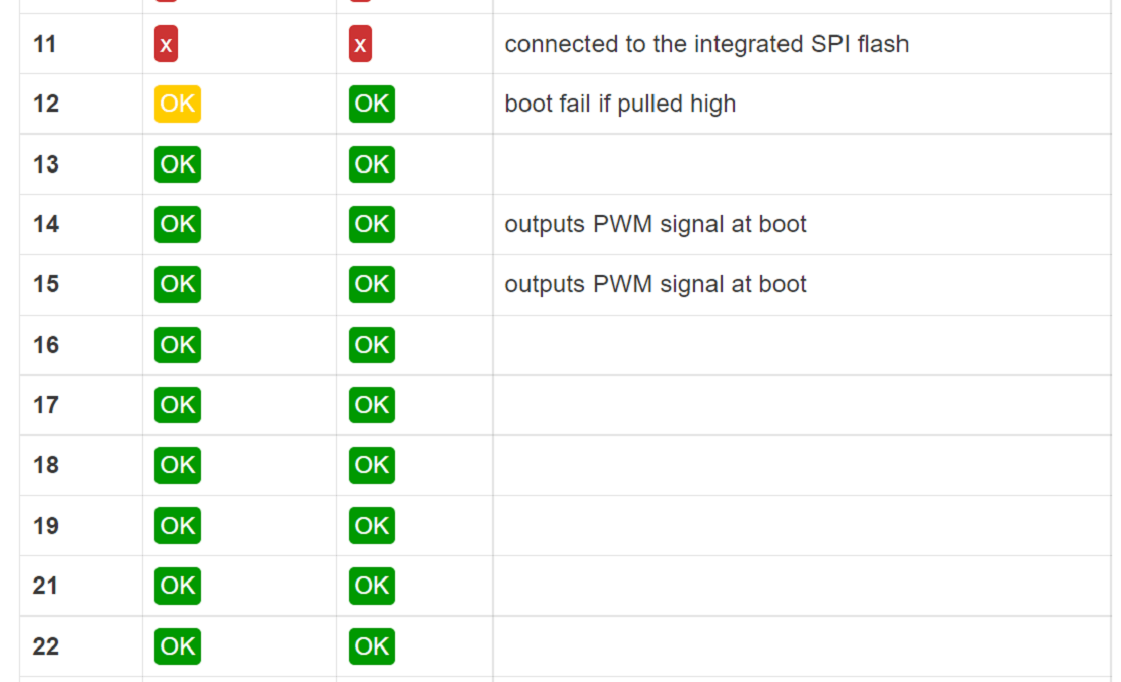
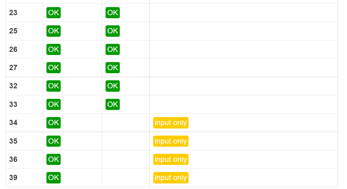
Additionally, there are pins with specific features that make them suitable or not for a particular project. The following table shows what pins are best to use as inputs, outputs and which ones you need to be cautious.
The pins highlighted in green are OK to use. The ones highlighted in yellow are OK to use, but you need to pay attention because they may have an unexpected behavior mainly at boot. The pins highlighted in red are not recommended to use as inputs or outputs.
 |
 |
 |
Comparison of Microcontrollers
| Parameters | Arduino Uno | ESP 32 | ESP8266 | Raspberry Pi Pico |
|---|---|---|---|---|
| Microcontroller | ATMega328P | ESP32 | ESP8266 | RP2040 |
| Core | Single core | Dual core | Single core | Dual core |
| Architecture | 8 bit RISC | 32 bit LX6 with 600 DMIPS | 32 bit LX106 | 32 bit ARM cortex M0+ |
| Clock Speed | 16 MHz | Up to 240MHz | Up to 160MHz | Up to 133MHz |
| Operating voltage | 5v | 3.3v | 3.3v | 3.3v |
| GPIO Voltage | 5v | 3.3v | 3.3v | 3.3v |
| Digital pins | 14 | 36 | 16 | 26 |
| PWM pins | 6 | 32 | 16 | 16 |
| Analog pins | 6 | 15 | 1 | 3 |
| SPI/I2C/UART/I2s | 1/1/1 | 4/2/2/2 | 2/1/2/2 | 2/2/2 |
| Wifi | NO | YES | YES | NO |
| Bluetooth | NO | YES | NO | NO |
| Built-in sensor | NO | Touch, Temperature, Hall Effect sensors | NO | Temperature sensor |
| Programming Language | Arduino IDE, C/C++ | Arduino IDE, C/C++, Micro Python | Arduino IDE, C/C++, Micro Python, Javascript | C/C++, Micro Python |
| On board Programming LED | D13 pin | D2 pin | D0 pin | GP25 pin |
| Flash | 32KB | 4MB | 4MB | 2MB |
| RAM | 264KB | 520KB | 128KB | 264KB |
| EEPROM | 1KB | NO | 520B | NO |
| Advantages | Best for beginners and Pro because there are so many modules and library. | Best for IoT projects | Best for IoT projects | Best for Machine Learning |
ESP32 vs ESP8266 - Pros and Cons
What's the difference between ESP32 and ESP8266? Should you use the ESP32 or the ESP8266 in your projects? The ESP32 and ESP8266 are cheap Wi-Fi modules perfectly suited for DIY projects in the Internet of Things (IoT) and Home Automation fields. Both chips have a 32-bit processor. The ESP32 is a dual-core 160MHz to 240MHz CPU, whereas the ESP8266 is a single-core processor that runs at 80MHz.
These modules come with GPIOs that support various protocols like SPI, I2C, UART, ADC, DAC, and PWM. The best part is that these boards come with wireless networking included, which makes them apart from other microcontrollers like the Arduino. This means that you can easily control and monitor devices remotely via Wi-Fi or Bluetooth (in the case of ESP32) for a very low price.
Alternatively, if you don't need to use its wireless capabilities, you can use the ESP32/ESP8266 to control inputs and outputs as you would do with an Arduino. However, you should take into account that the Arduino works with 5V logic, the ESP32 and ESP8266 work at 3.3V.
The ESP32 is the ESP8266 successor. It adds an extra CPU core, faster Wi-Fi, more GPIOs, and supports Bluetooth 4.2 and Bluetooth low energy. Additionally, the ESP32 comes with touch-sensitive pins that can be used to wake up the ESP32 from deep sleep, a built-in hall effect sensor, and a built-in temperature sensor (recent versions of the ESP32 don't come with a built-in temperature sensor anymore).
The ESP8266 is cheaper than the ESP32. Although it doesn't have as many functionalities, it works just fine for most simple DIY IoT projects. However, it has some limitations in the GPIO mapping, and it might not have enough pins for what you intend to do. If that's the case, you should get an ESP32.
The ESP32 is much more powerful than the ESP8266, comes with more GPIOs with multiple functions, faster Wi-Fi, and supports Bluetooth. However, many people think that the ESP32 is more difficult to deal with than the ESP8266 because it is more complex. On the contrary, it is as easy to program the ESP32 as the ESP8266, especially if you intend to program it using the "Arduino language" or MicroPython.
Programming ESP32 using Micro-python
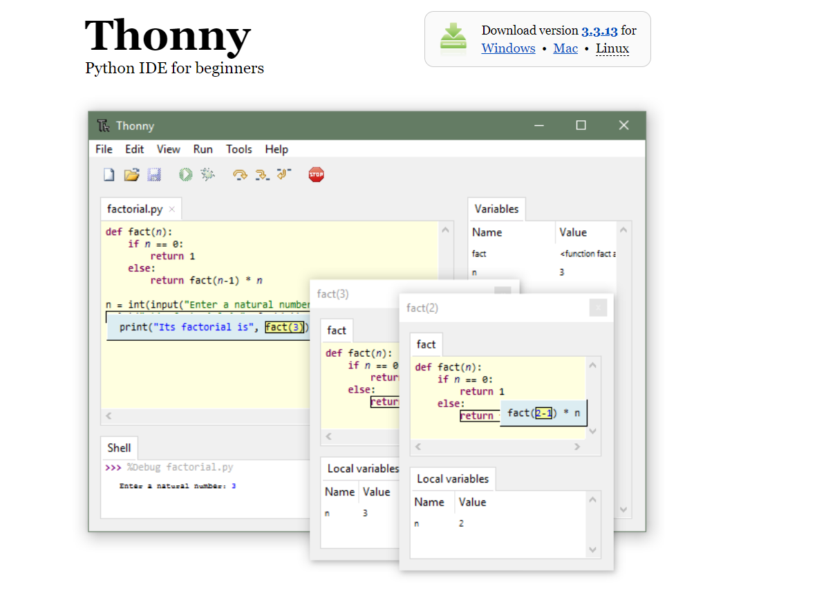
If we want to program your ESP32 and ESP8266 with MicroPython firmware, it's very handy to use an IDE. We programmed the ESP32 boards using MicroPython, and Thonny seemed a good choice. It is compatible with Windows, Mac OS X, and Linux. It even comes installed by default on the Raspberry Pi OS. Additionally, it's easy to install.
What is MicroPython?
MicroPython is a Python 3 programming language re-implementation targeted for microcontrollers and embedded systems. MicroPython is very similar to regular Python. Apart from a few exceptions, the language features of Python are also available in MicroPython. The most significant difference between Python and MicroPython is that MicroPython was designed to work under constrained conditions. Because of that, MicroPython does not come with the entire pack of standard libraries. It only includes a small subset of the Python standard libraries, but it includes modules to easily control and interact with the GPIOs, use Wi-Fi, and other communication protocols.
Installing Thonny IDE
To install Thonny on Windows PC, we followed the next steps:
1. Click here to go to thonny website.
2. Download the version for Windows and wait a few seconds while it downloads.
 |
3. Run the .exe file:
 |
 |
4. After completing the installation, open Thonny IDE. A window as shown in the following figure should open.
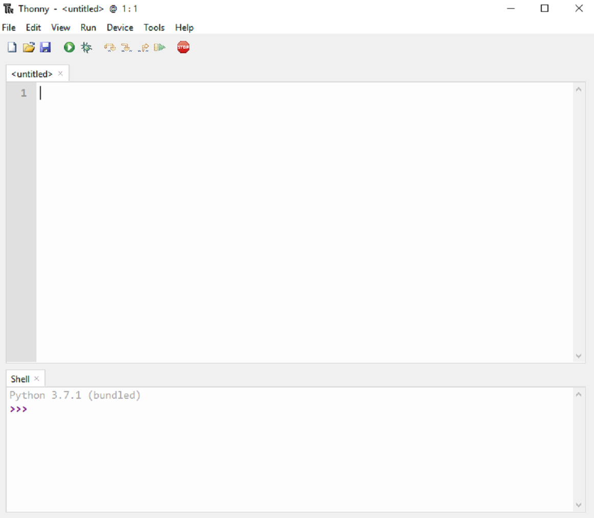 |
Flashing MicroPython Software
MicroPython isn't flashed onto the ESP32 or ESP8266 boards by default. The first thing you need to do to start programming your boards with MicroPython is flash/upload/burn the firmware.
Downloading MicroPython Firmware
1. Click here to go to the MicroPython Downloads page.
2. Install micro-python if you don't have it installed already
3. Here is the quick link for ESP32 board. You should see a similar web page (see figure below) with links to download .bin files. Download the latest release.
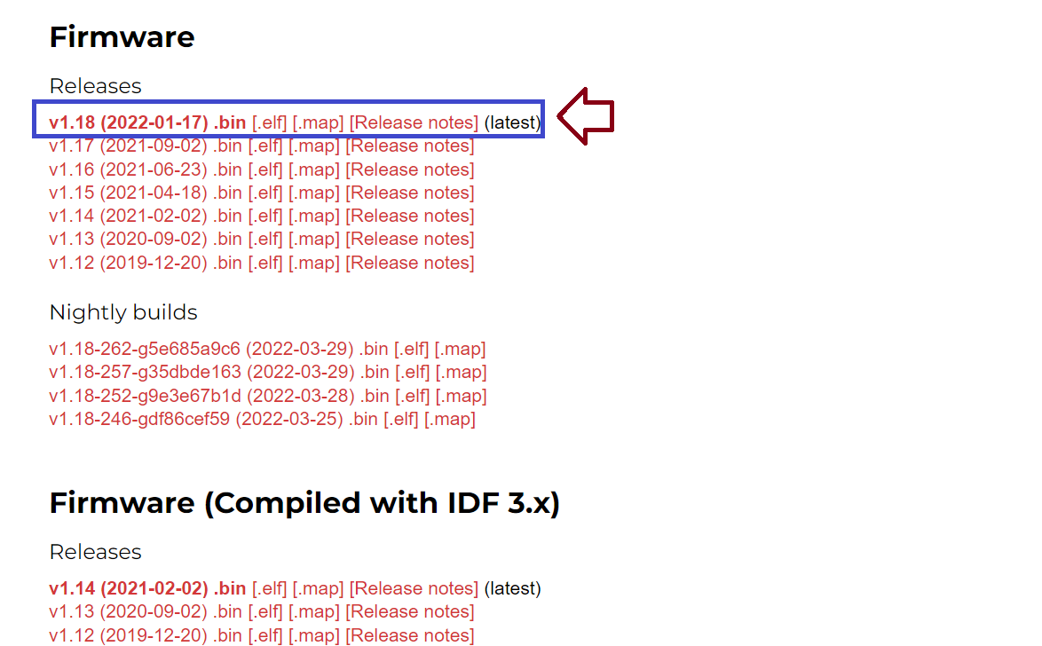 |
Flashing MicroPython Firmware using Thonny IDE
We followed the next steps to flash MicroPython firmware on our board using Thonny IDE.
1. We connected our ESP32 board to oour computer.
2. Opened Thonny IDE. We then went to Tools > Options > Interpreter.
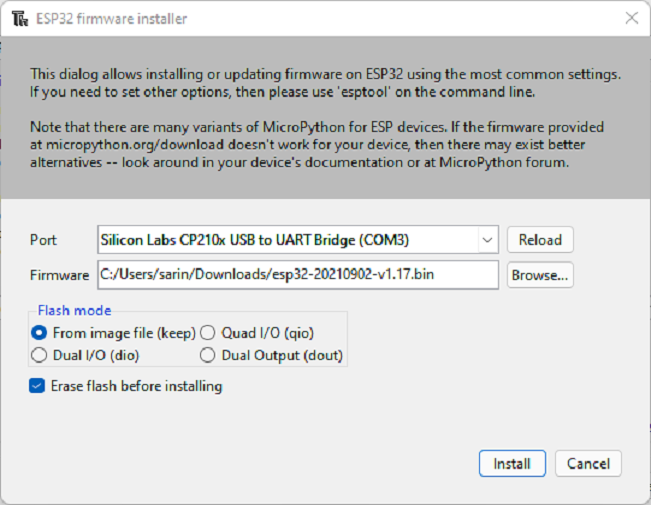
3. We selected the interpreter we wanted to use accordingly to the board we are using and select the COM port the board is connected to. Finally, we clicked on the link Install or update firmware. After that, we selected the port once again, and then clicked on the Browse button to open the .bin file with the firmware we downloaded on the previous step. We selected the options as shown in the picture below and finally click on Install. After some time, the installation should be completed.
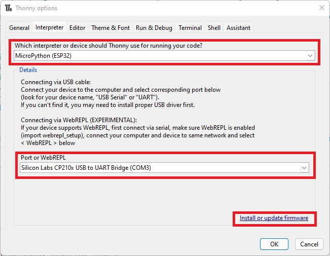 |
 |
Testing the Installation
We connected the board to computer using a USB cable. To test the installation, we needed to tell Thonny that we want to run MicroPython Interpreter and selected the board we were using.
1. Then we went to Tools > Options and selected the Interpreter tab. We made sure that we selected the right interpreter for our board as well as the COM port.
2. Thonny IDE got connected to our board and we saw the prompt on the Shell.
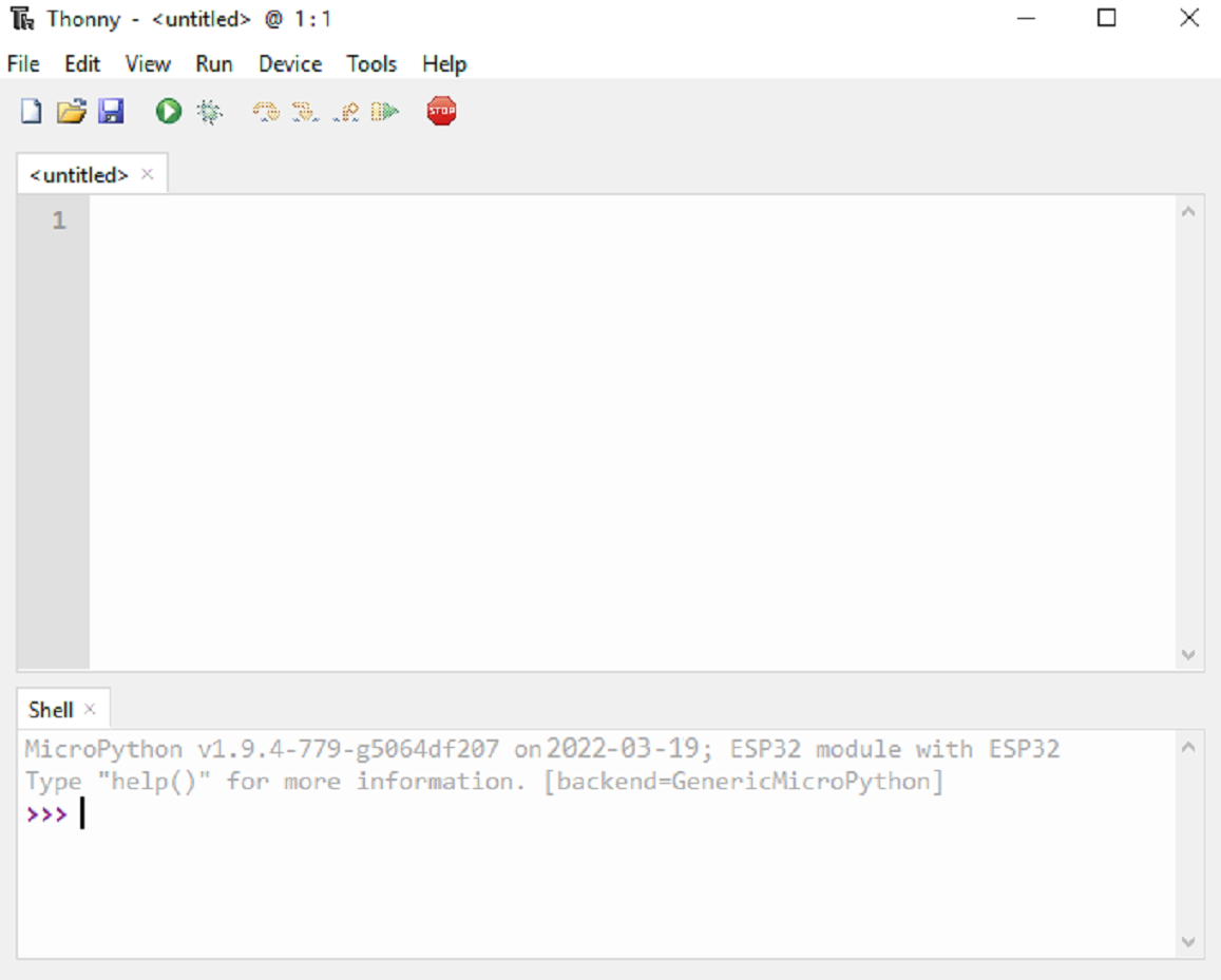 |
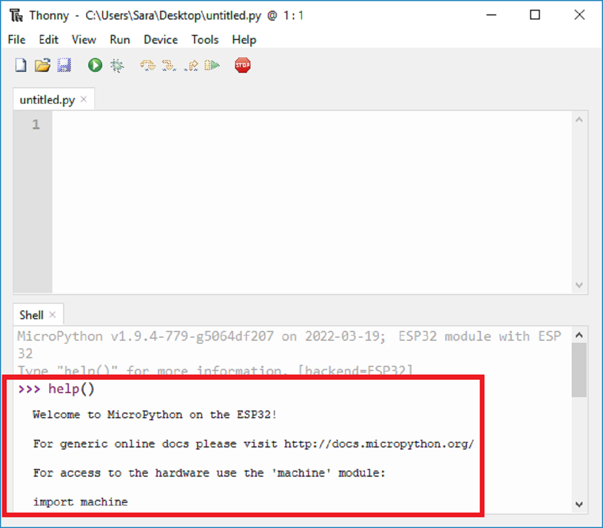
3. We typed the command help() in the Shell and saw if it responds back. It responded back, everything is working fine. Now, we were ready to do blink programs.
 |
Programming ESP32- Blink
We did programming to blink the inbuilt LED on ESP32 development board and also externally connected LED. Following is the video of the same.
Programming ESP32 using VS Code
OS used: MacOs
Softwares used: VS Code, Esptool, Terminal, VS Code Extension Pymakr
1. First open your browser and search for esp32 firmware by clicking this.
-Then open your Terminal and type the commands "cd mkdir $folder_name" to create a folder to work in
-Then move the downloaded .bin file to the $folder_name.
-Then open another Terminal window in the $folder_name directory.
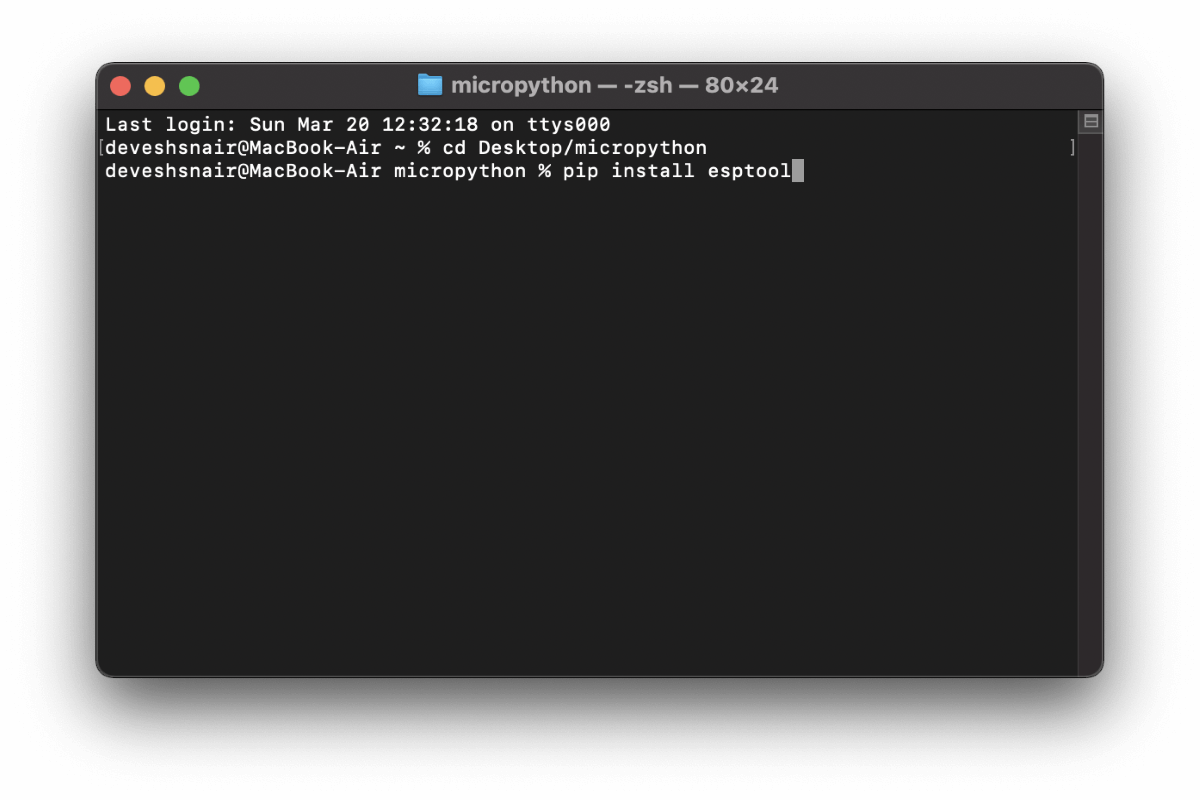
-Type the commands "pip3 install esptool" as shown below.
 |
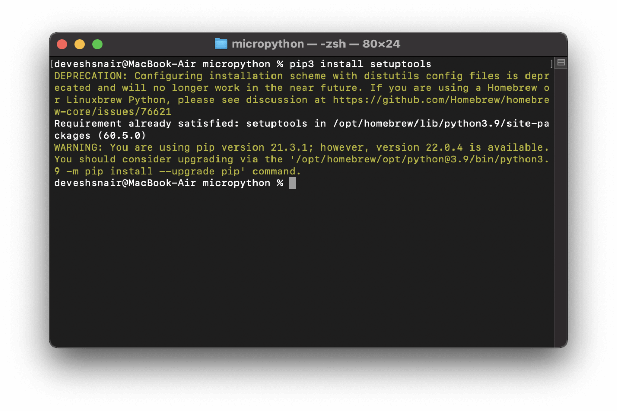
After the installing esptool we need setups so type "pip3 install setuptools"
 |
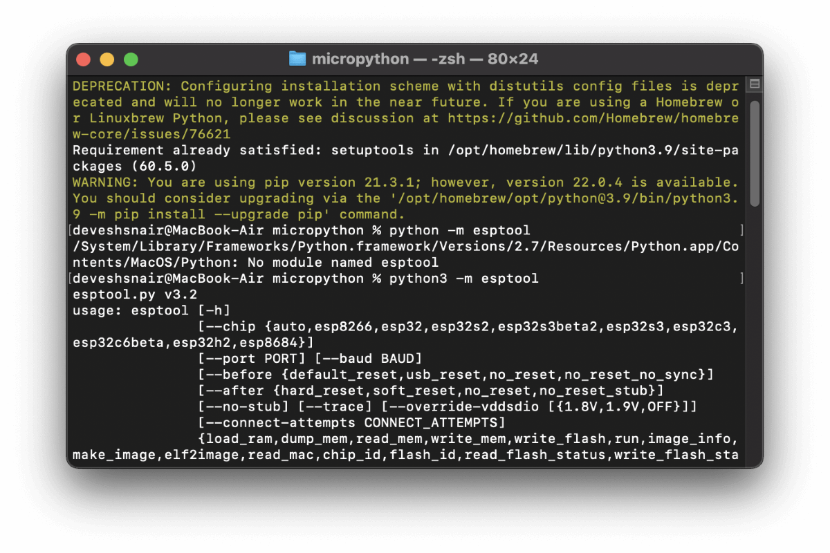
Since all the necessary softwares are downloaded and installed now connect the ESP32 to the USB port. Then type the command "python3 -m esptool". (This command will check esptool is working fine on the PC or not). You should get an output shown below. It means that esptool software is working fine.
 |
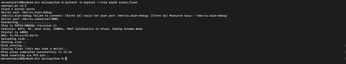
Now type the command "python3 -m esptool -chip esp32 erase_flash". Esp32 will be flashed.
 |
After which type the command shown in the image below. The bootloader will be flashed to esp32.
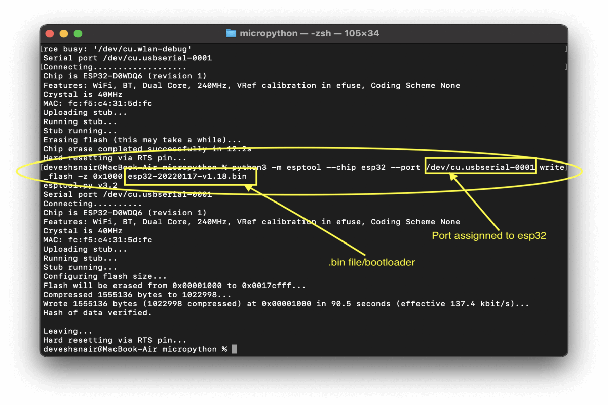 |
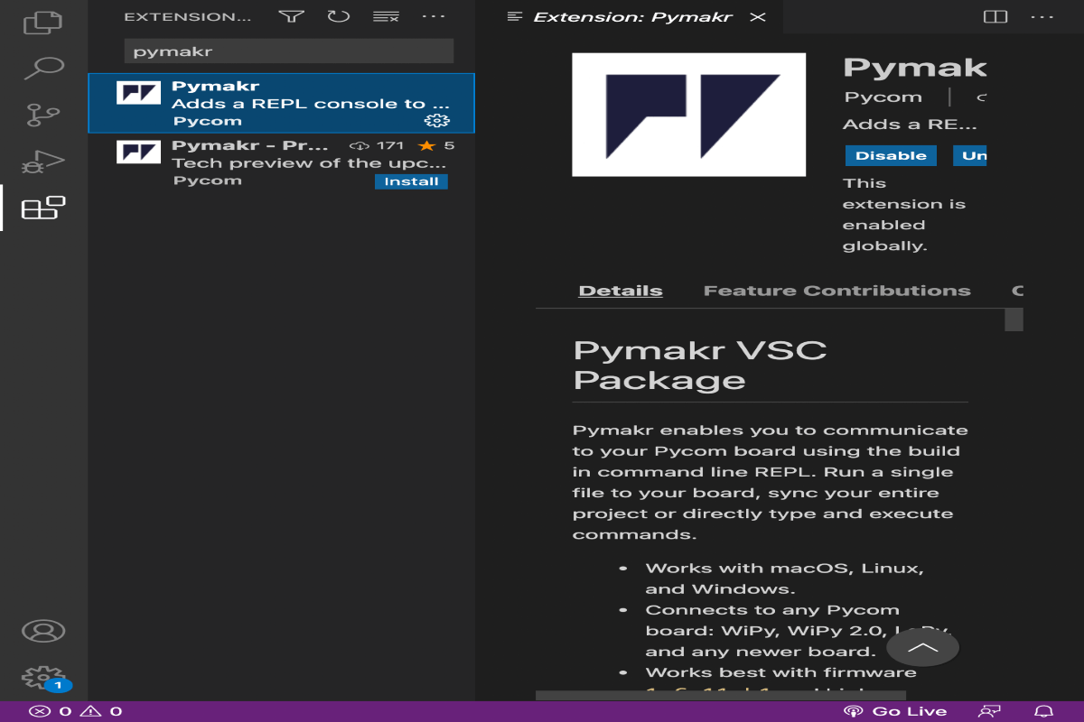
Now Open VSCode. In the Extensions tab search for "pymakr". The extension has two versions currently and we used preview one for the Mac i.e V.2.0, windows user can use V.1.7.7. Then, istall the extension, remember to install Node.js it is a dependency for the software. Create a new .py file in the directory and save.
Go to terminal, choose the drop down arrow in the terminal and choose "pymakr" and select the port to which ESP32 is connected. Do the setup.
 |
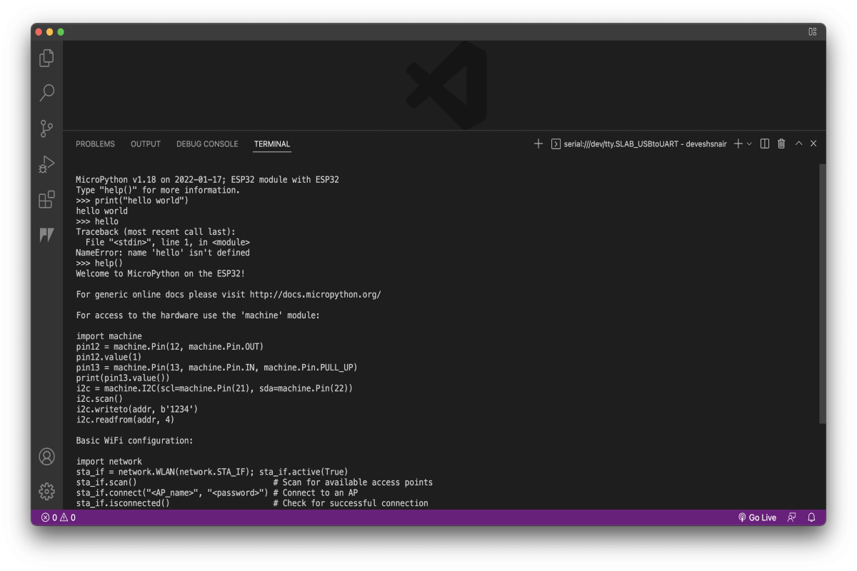
After the set up, your ESP32 board should be ready to communicate with your pc.
Just type "help()" in the terminal for checking the connection if you get the an output shown below then Bingo!
 |
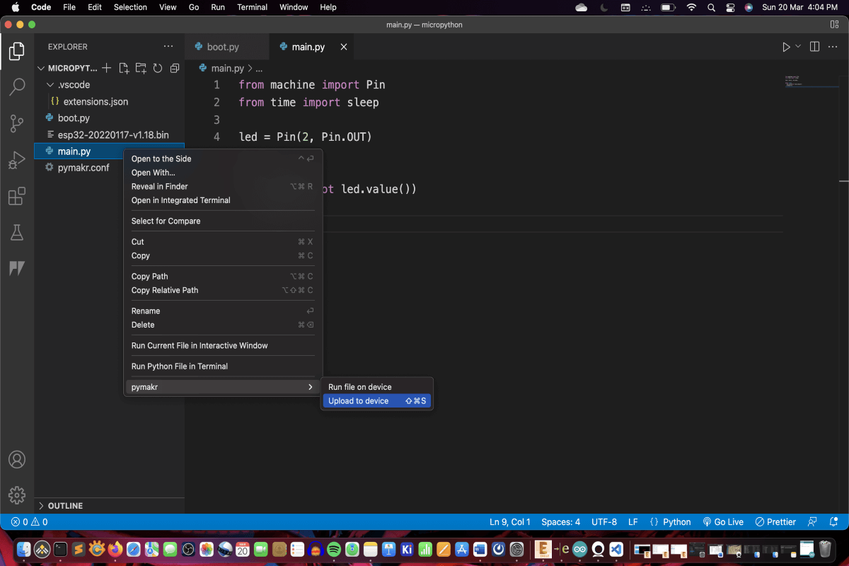
Then, go to the .py file that you wrote for ESP32. We wrote a blinking LED code for the same, then right click and click upload to device from the menu.
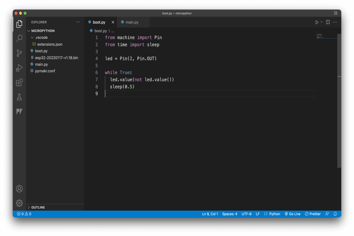 |
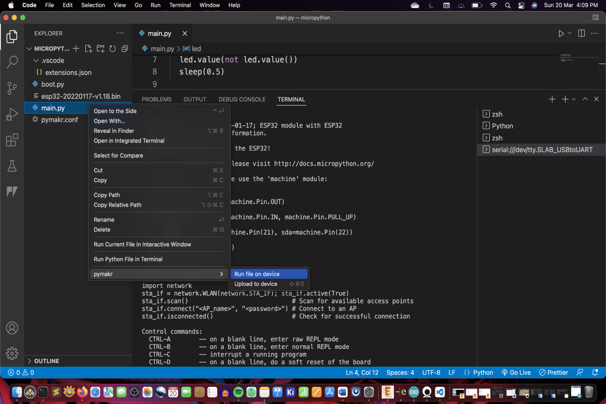
After this, follow the steps shown below to upload and run the code in your ESP32. Select the port for ESP32 is connected to and press enter to upload.
 |
Select the port for ESP32 is connected to and press enter to run. The code should be running on ESP32. Tip: If ports are not shown in pymakr's extension tab, then click add device and follow the procedure.
 |
Refrence link used for the ESP32 programming: