Group Assignment #11: Interface and Application Programming
This assignment is about documenting what we learned in Interface and Application Programming week that includes understanding different tools for developing applications and interface programming. We also learned how to use these tools, their features and and their purposes.
Objectives of the Group Assignment:
- Compare as many tool options as possible
For the purpose of this group assignment, we learned different application tools like MIT app Inventor, Processing, etc. We have explained brief about each of these tools and how did we use them.
1. Processing:
Processing is the language; with the help of this, we can learn to code with visual arts. Processing is helpful for students, artists, designers, researchers, and hobbyists who use Processing for learning and prototyping. Processing is the programming language for learning how to code in the context of the visual arts and visual literacy within technology. Processing is a free graphical library and integrated development environment (IDE) that facilitates computer programming in a visual setting for learners with limited programming knowledge. Processing employs the Java programming language; we can add classes, mathematical function operations, etc. It also includes a graphical user interface to help with the compilation and execution stages. Click here to go to the Processing Website.
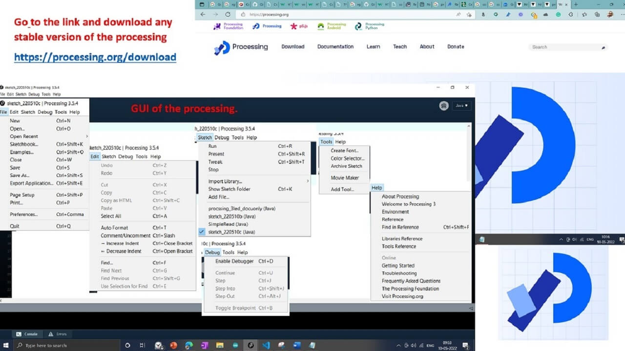
The graphical user interface of the Processing IDE is just like the Arduino IDE. We downloaded Processing software from the Download section on the Processing website.
Features of Processing:
- Processing includes a sketchbook, a minimal alternative to an integrated development environment (IDE) for organizing projects.
- Every Processing sketch is actually a subclass of the PApplet Java class (formerly a subclass of Java's built-in Applet) which implements most of the Processing language's features.
- When programming in Processing, all additional classes defined will be treated as inner classes when the code is translated into pure Java before compiling.
- Processing also allows for users to create their own classes within the PApplet sketch.
- Interactive programs with 2D, 3D, PDF, or SVG output
Credits and Reference: Click here.
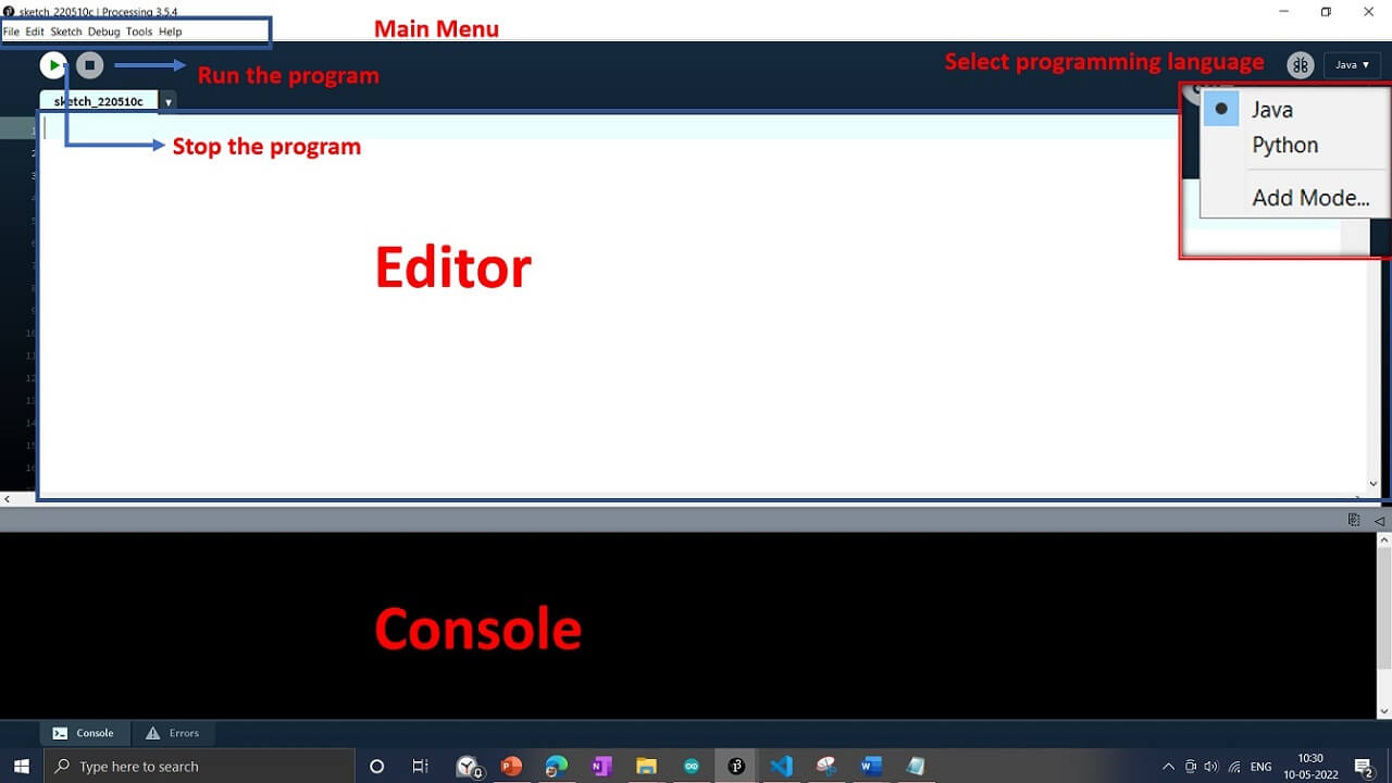 |
Different options are available in the menu bar shown below.
 |
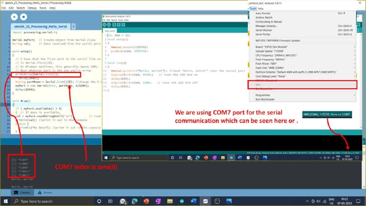
Like Arduino, the Processing code consists of three sections: initially, we call the libraries and then declare variables. Then there's a void with Setup and another with the "draw" loop. printArray(Serial.list()); command is used to print the list of available COM ports for the serial communication. Then a list of the array gets available on the console; we need to select the com port that we have selected in the Arduino ide to send the command. Command used to select the COM port is Serial.list()[0].
1a. Using Processing for controlling RGB LED ON/OFF:
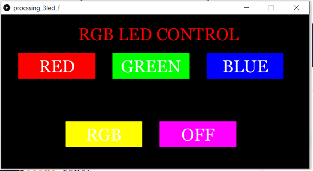
For this assignment, we have developed an application that consists of 5 buttons, three for individual LEDs, one for ON all LEDs at the time, and one for off all lEDs as shown below.
In our case, we are using COM7 for the serial communication; the processing console shows the list, and the com7 index is 0; hence we have added the command Serial.list()[0] and assigned the variable as port name to it.
 |
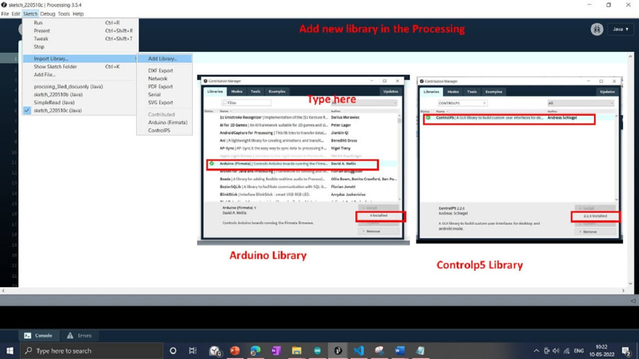
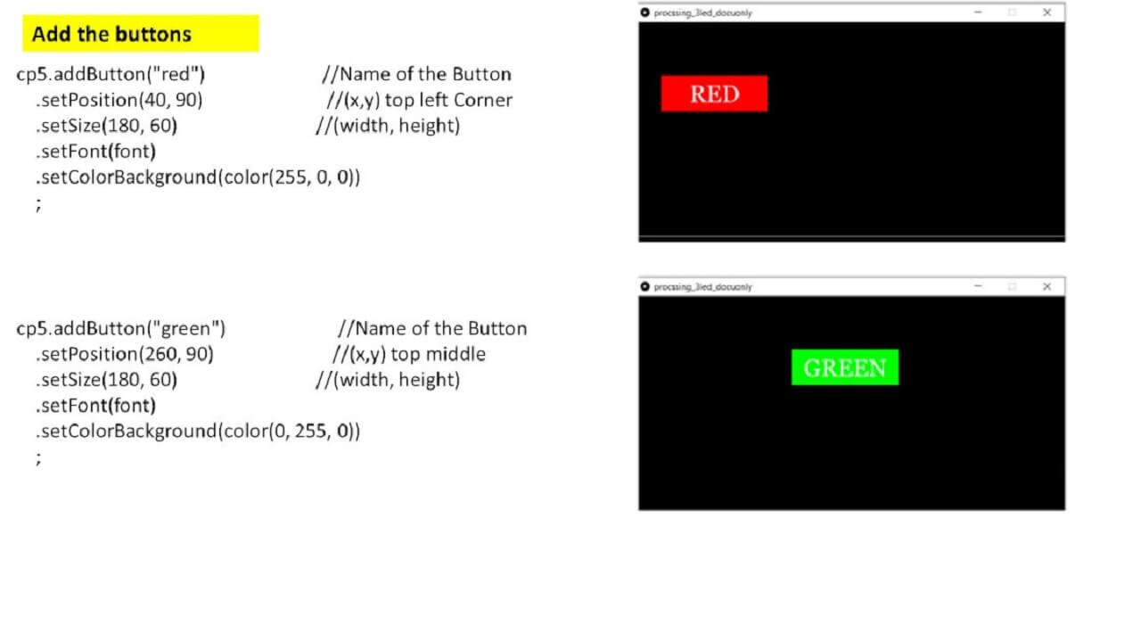
We want to create the button for three different LEDs and control them during the Processing. We used the control5library controlp5. controlP5 A GUI (graphical user interface) library for Processing. With the help of the controlp5 library, we can add include Sliders, Buttons, Toggles, Knobs, Textfields, RadioButtons, and Checkboxes, amongst others, and can be easily added to a processing sketch. We have referred to some examples here. We found this example for the button code. Then we modified this code as per our requirement. Modifications in code and final code are shown below.
To add the buttons, we have added the controlp5 library using command line import controlP5.*;
 |
We have developed an application that consists of 5 buttons, three for individual LEDs, one for ON all LEDs at the time, and one for off all lEDs.
 |
 |
Final Application:
 |
Then we used the application to control 3 LEDs using our board as seen in the video below:
1b. Using Processing to develop Temperature Monitor GUI:
We also have developed an application to graphically display the Temperature monitor for one of our projects using DS18B20 sensor as shown below.
 |
Developing Temperature monitor GUI:
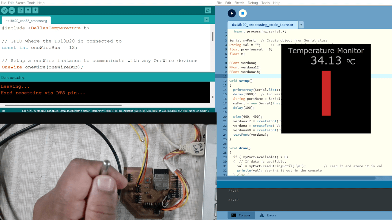
The next task is to make a visual representation of the temperature values from a sensor and display it on the screen . In this case, we have used the Arduino program in, which we read the temperature of the DS1820 sensor using the Serial.print(temperatureC); command as shown in the code below.
Below is the code that we have written in Processing IDE for developing the temperature monitor GUI. We will explain the code below.
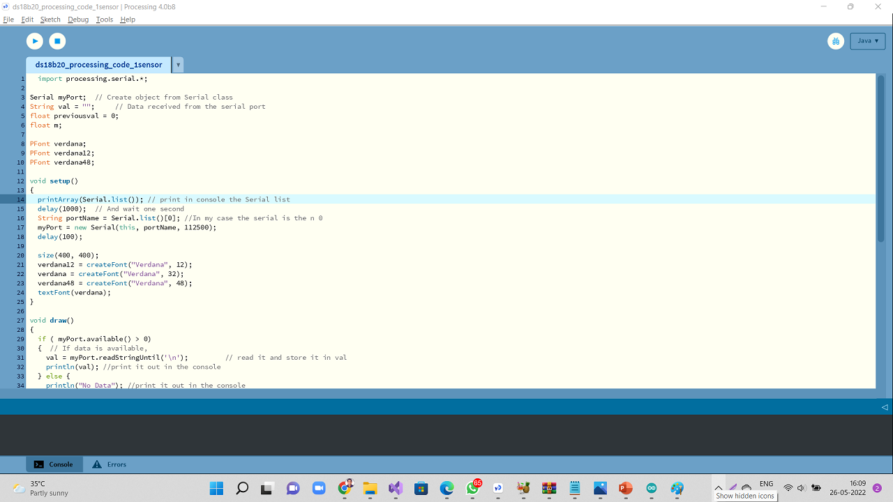 |
Copy/Download the processing sketch for Temperature monitor GUI:
Click here to see/copy the above processing sketch/program for temperature monitor GUI.
Explaination of the code:
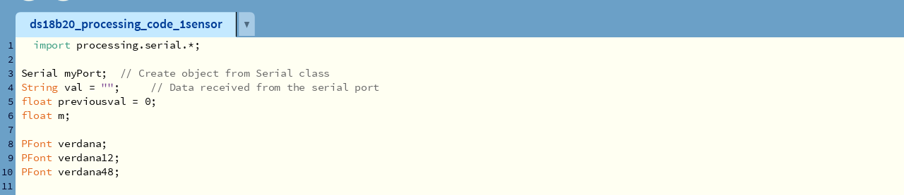
First, we called the processing.serial.* library. Added myPort as an object to be created from the serial class. We defined "val" as a string to store data received from the serial port. Defined floats and other variables for fonts used.
 |
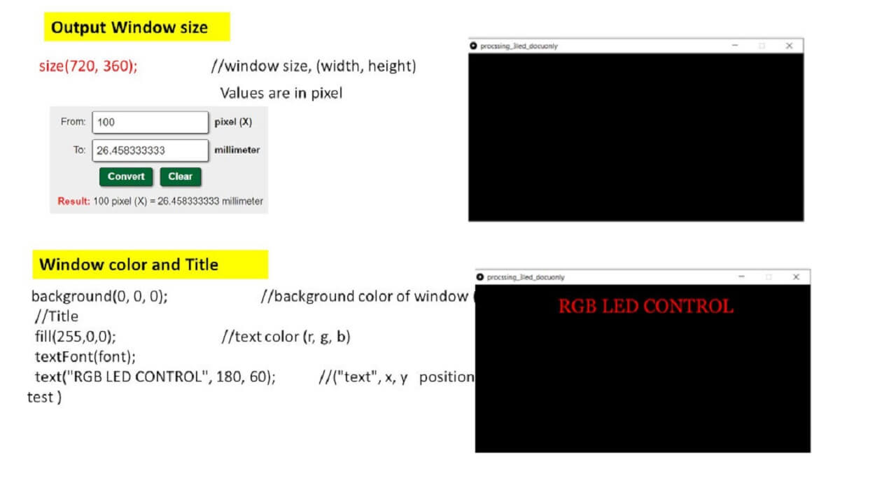
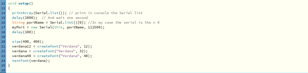
In void setup(), added command Serial.list()[0] for port COM17 from, which the data is received from the project board. It is also displayed in to the console with a baud rate of 112500 (same as that of in arduino IDE program). We have also set-up font sizes for the monitor here. A 400x400 pixels screen with size (400, 400) has been set-up for GUI.
 |
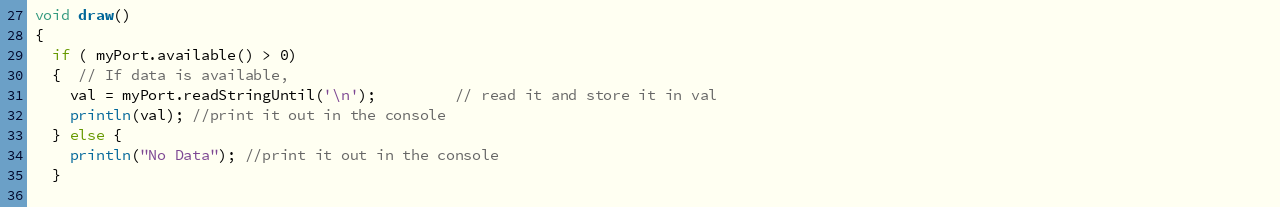
In void draw(), data received from the serial port is printed against a variable "val" that we had already declared at the beginning of the code. If the port does not receive a data, it will show, 'No Data' in to console.
 |
Now, we have defined parameters for the temperature monitor GUI including its background color, font, fontsize, and text to be displayed in to the GUI.
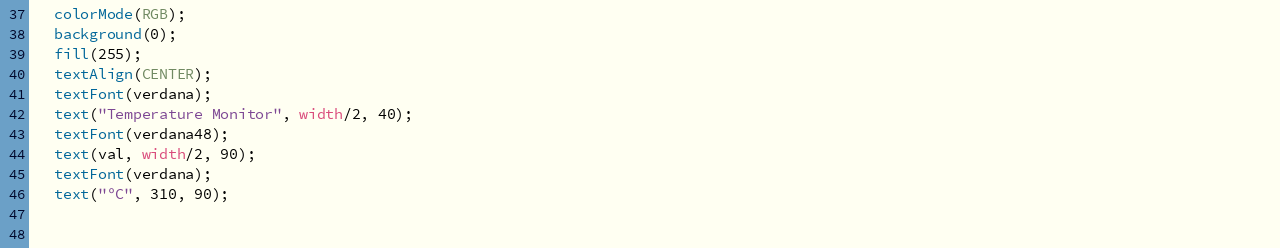 |
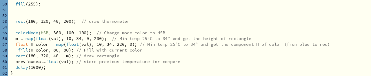
In this last section of the code, we have defined Colors for varying temperature values to be displayed on the GUI as per the serial data being received.
 |
2. MIT App Inventor:
MIT App Inventor is a block-based programming tool through, which one can create fully functional apps for Android devices such as smartphones, tables, etc. It was originally provided by Google, and now maintained by the Massachusetts Institute of Technology (MIT). MIT App Inventor is an open source software, which can be easily used by everyone as it is a simple tool for beginner for making their first application. Go to MIT app inventor website by clicking here.
The graphical user interface of the Processing IDE is just like the Arduino IDE. We downloaded Processing software from the Download section on the Processing website.
Features of MIT App inventor:
- MIT App Inventor is an open source software.
- We can create more than one project in MIT App Inventor and can make changes in it whenever required.
- In MIT App Inventor, we have to write a code by connecting the blocks as it has block level programming.
- We can generate QR code of our project and scan it using MIT AI companion app to open our application on any android device. We can also download .apk file and install on that android device instead of scanning through AI companion app everytime.
Collecting DS18B20 Temperature sensor data on application developed through MIT app inventor and Google Firebase.
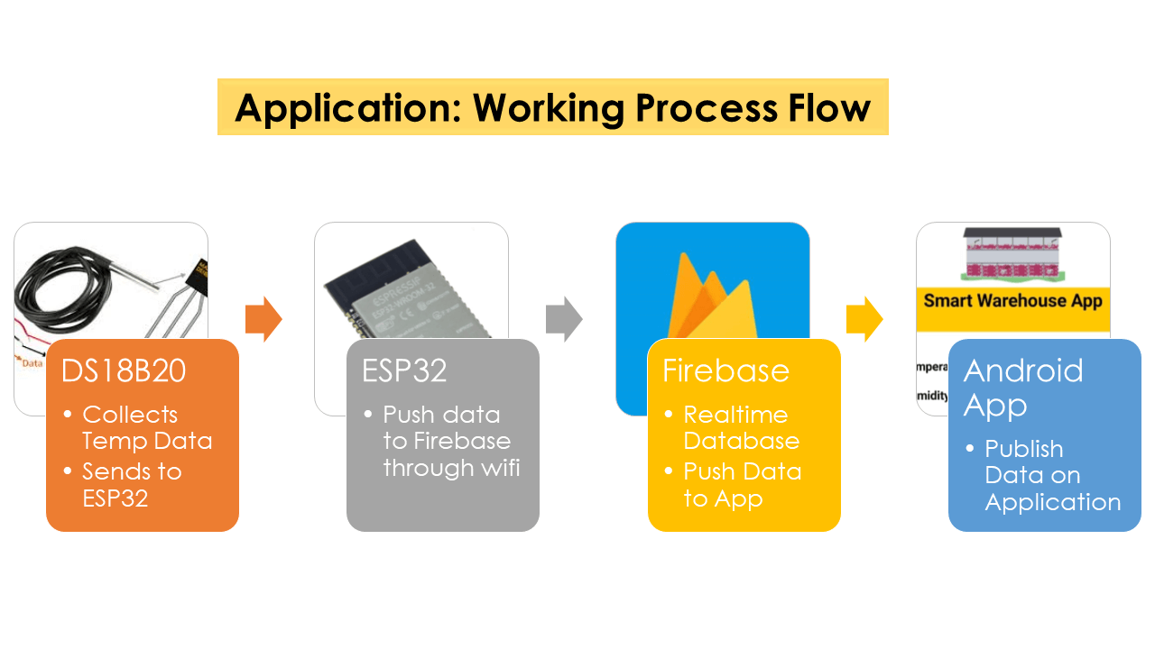
We have developed android app using MIT app inventor. To do this, we are sending sensor data to the Android app through Google Firebase using Arduino IDE. The application displays sensor readings on our smartphone. The sensor readings could be accessed anywhere and anytime conveniently. We have used Arduino IDE to program the project board (ESP32- Wroom), which is be connected to multiple DS18B20 sensors. The sensor readings are sent to the Google Firebase database, which will push the sensor readings in real-time through the app built using MIT App Inventor.
Following is a work process flow of the application:
 |
Following is Google Firebase webpage.
.png) |
Following is MIT app inventor webpage.
.png) |
Inside MIT app inventor, you will have a designer screen. This is, where the user interface of the app has been designed. We can add text, buttons, images and various other functionalities to our app by dragging and dropping components from the palette (the one on the left) to the viewer area (second from the left). Then we can set their attributes through the 'Properties' area on the very right side of the screen. The selected components will be listed in the second column from right as highlighted in the image below.
.png) |
Creating User Interface:
This is how the UI in designer workspace looked like after required component placement.
.png) |
Working in Blocks layout:
THe block programming screen for the application development.
.png) |
After completing block programming, go to the Designer workspace and click on 'Connect > AI companion' tab on the top.
.png) |
This opened up the QR code and 6 digit code on the screen for us to be able to connect to the AI companion app on android.
.png) |
Go to playstore and install the 'AI companion app' and once installed, scan the QR code on the computer screen by clicking on 'scan QR code' button on AI companion app or use 6 digit code to connect as shown below.
.jpg) |
.jpg) |
The app displays the temperature values as shown in the images below.
.jpg) |
.jpg) |
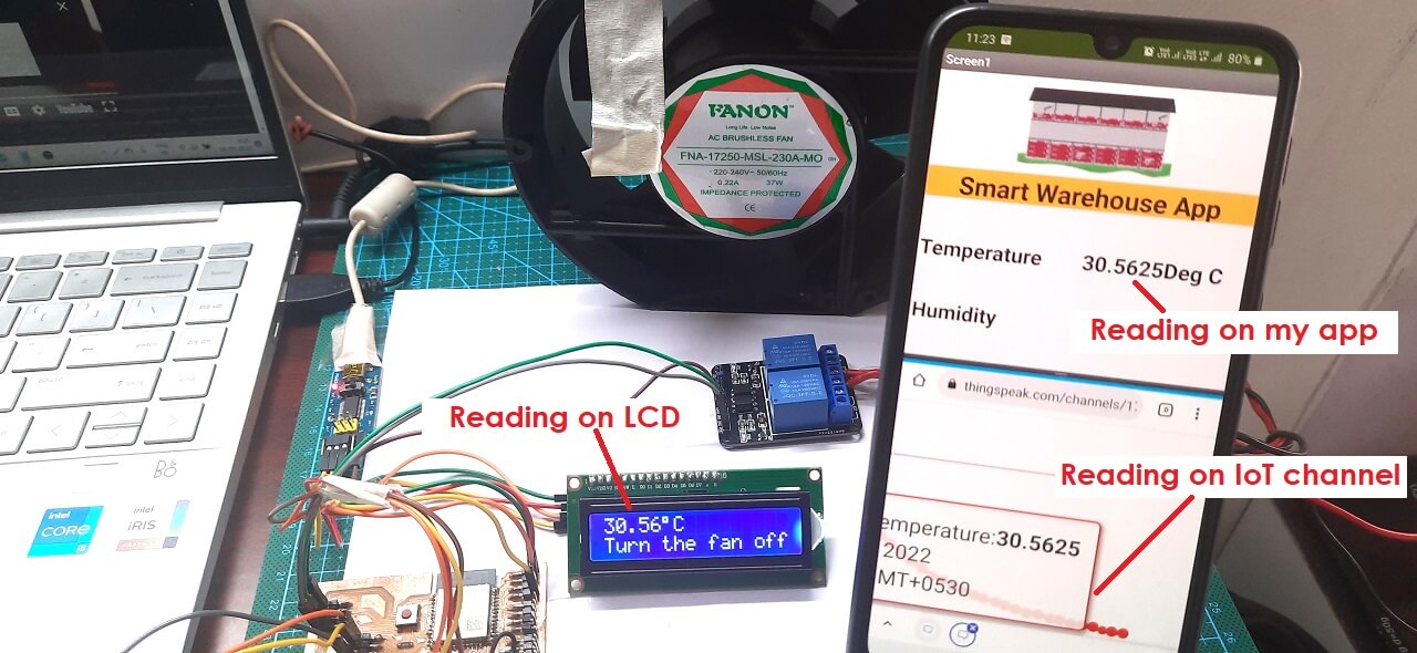 |