Group Assignment: Mechanical Design, Machine Design
This assignment is about documenting what we learned in Mechanical Design and Machine Design week that includes what all we did as a group in making a machine. The tasks were divided as per the processes and yet work was completed through a collaborative and concurrent approach. This documentation includes our concept, brainstorming and processes (work break-down) we followed in designing and constructing our machine.
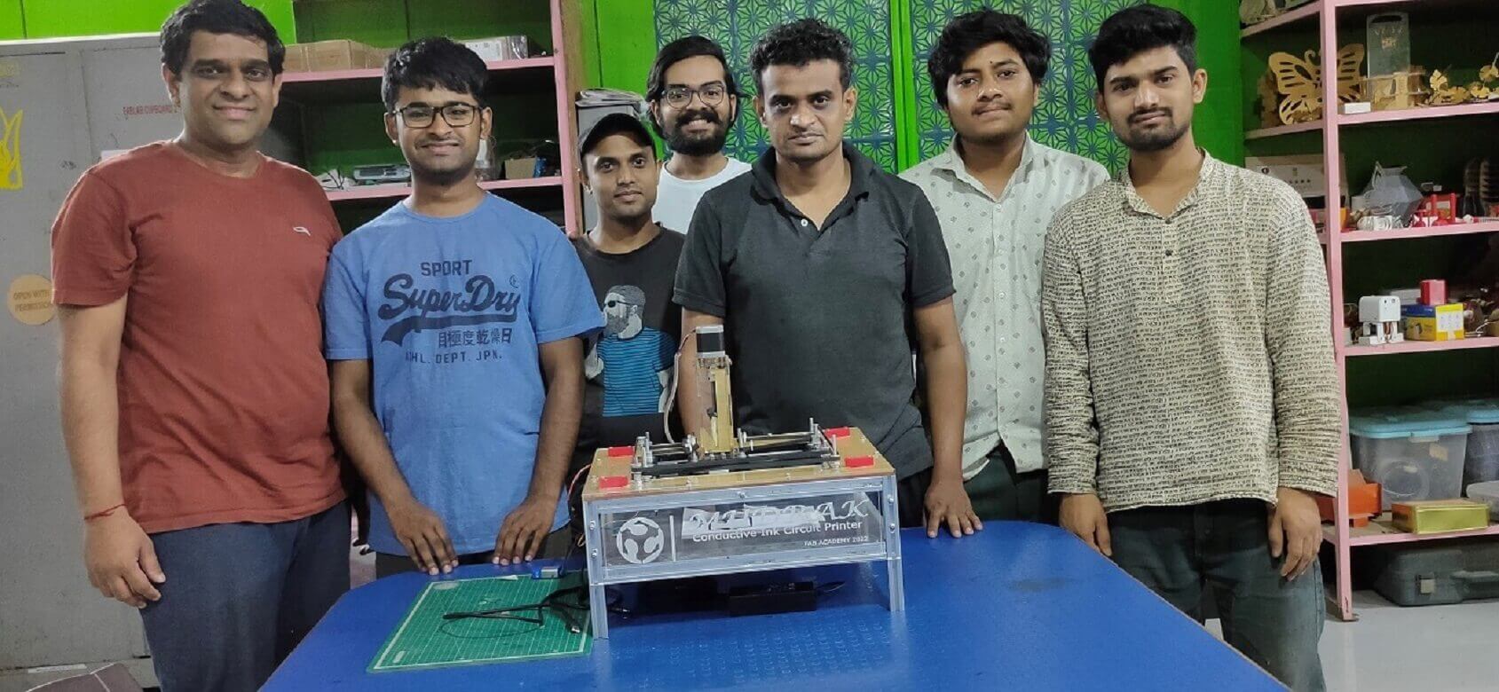
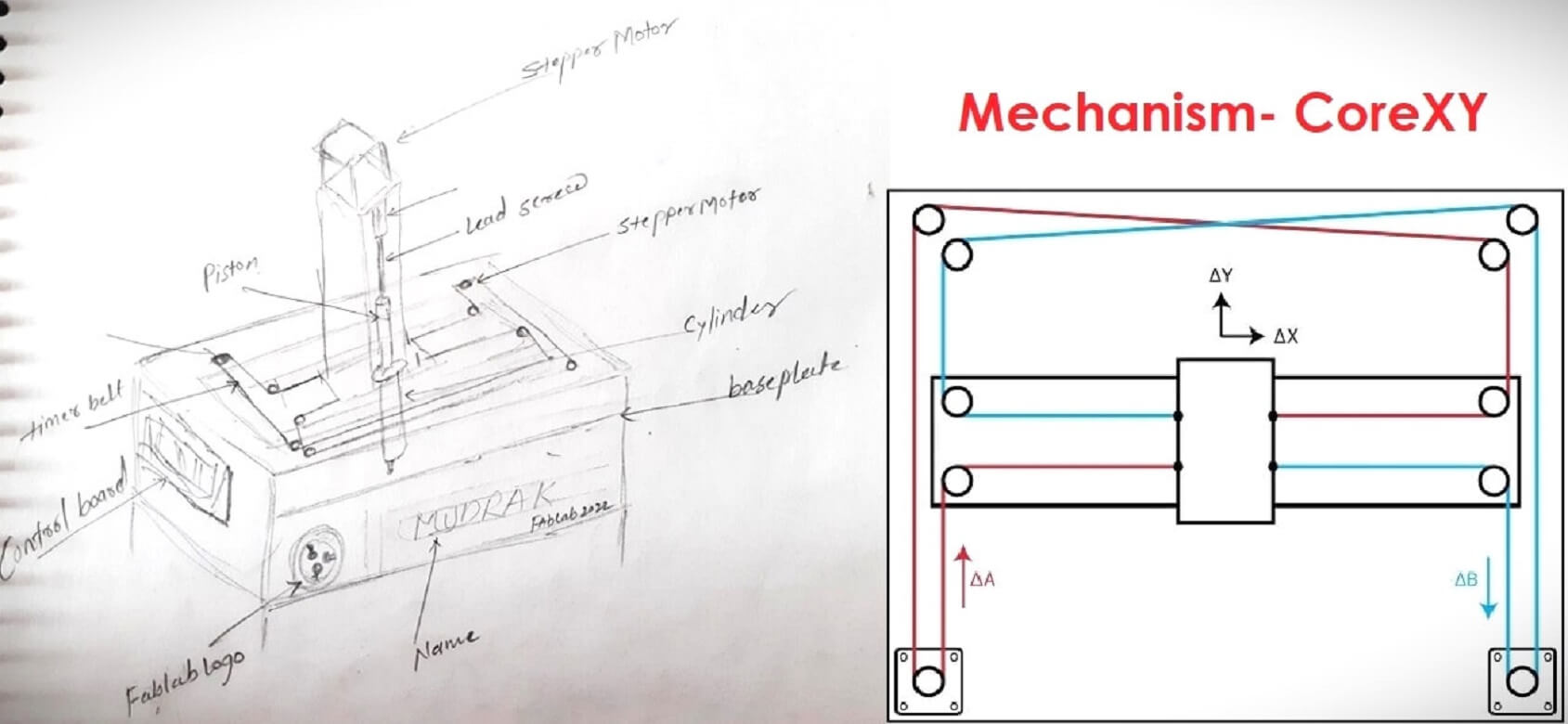
Name of our Machine is 'Mudrak'. It is a Hindi word, which in English means a 'Printer'.
Objectives of the Group Assignment:
Mechanical Design
- Design a machine that includes mechanism + actuation + automation + application
- Build the mechanical parts and operate it manually
- Document the group project and your individual contribution
Machine Design
- Actuate and automate your machine
- Document the group project and your individual contribution
Our Hero shots and videos:
 |
 |
 |
 |
Concept
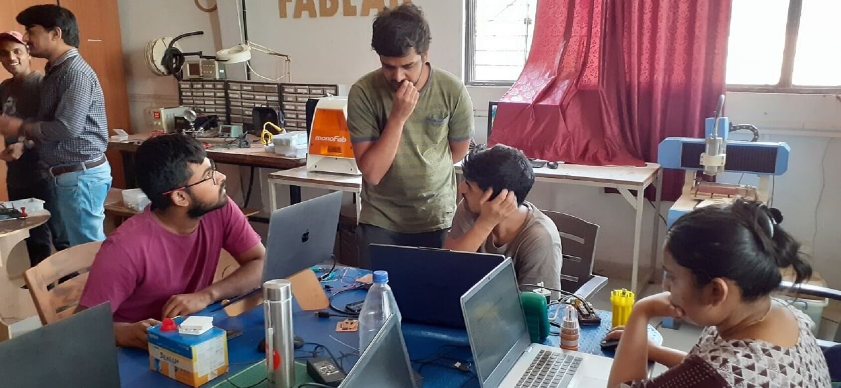
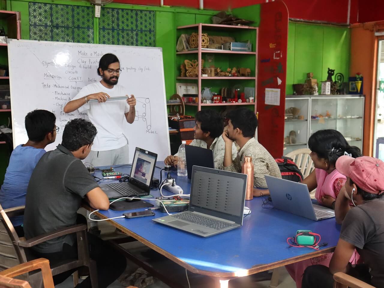
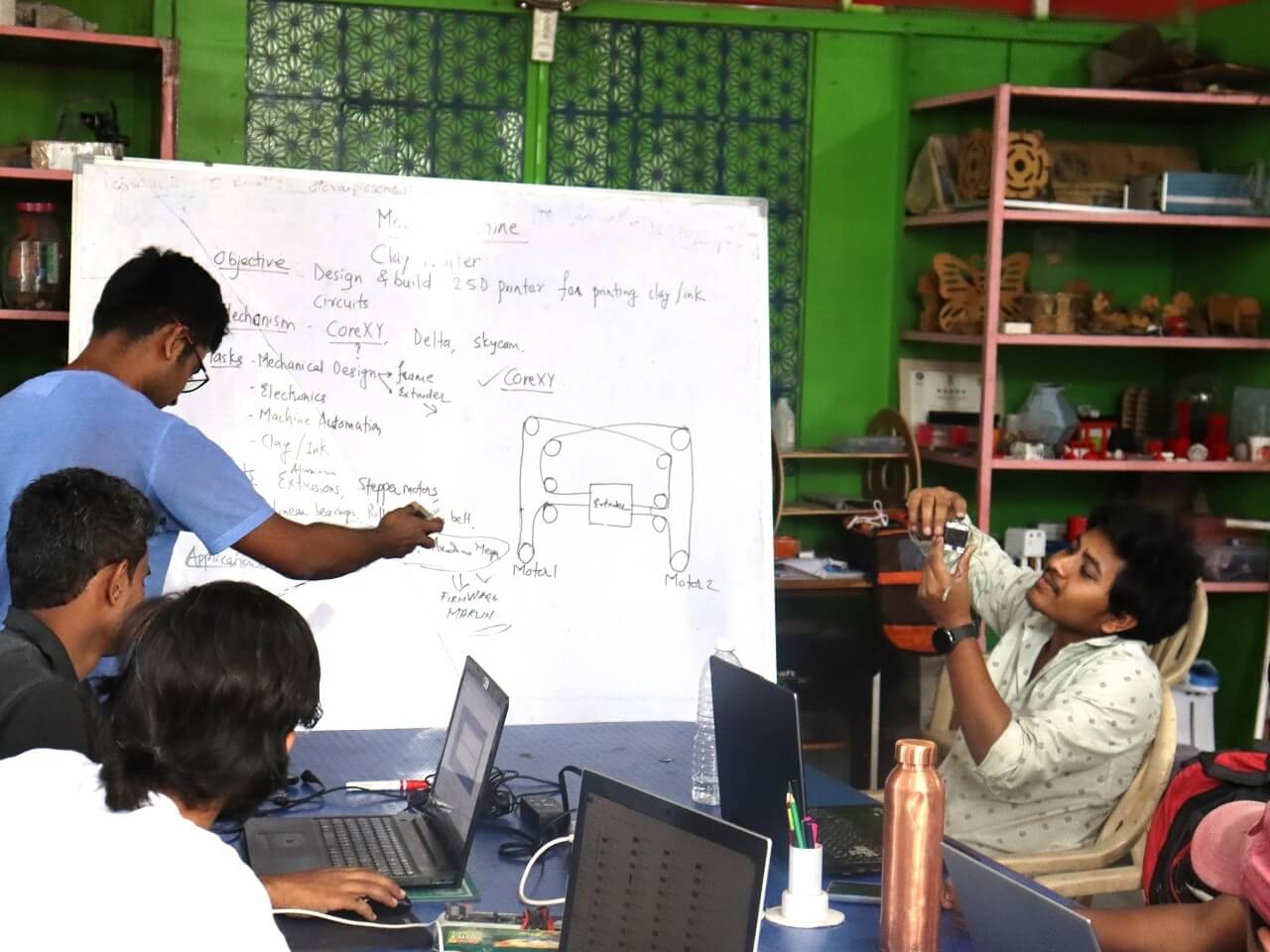
We had a brainstorming session to decide on the machine, it's applications and what kind of mechanism should the machine have. We had different ideas; however, we thought of making a machine that can print circuits using materials like conductive clay or ink, etc.
 |
 |
The idea behind using a conductive clay or ink is to make a low-cost material, which is easily available. We thought of making the conductive clay using a play dough (made of common flour) that can be safely handled by the children. We went through the following video to know more about the conductive clay. Source and Credit for the literature: TED Talk youtube channel
We also went through Squishy circuits website and other websites for refrence.
Selection of a Mechanism:
Together as a group, we went through different mechanisms that can be best suited to design and build a printer. We concluded to use CoreXY mechanism in our printer. Click here for Reference and credits.
 |
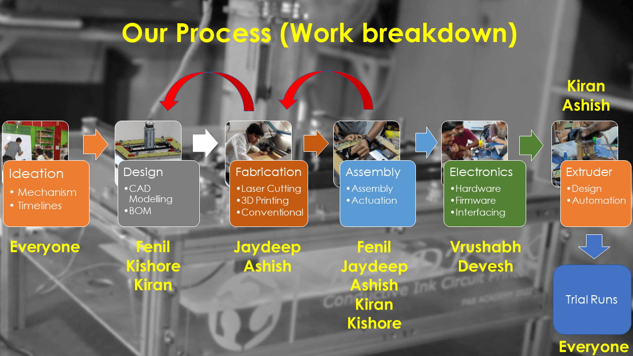
Process Flow
We assigned following tasks amongst ourselves building the machine.
1. Fenil and Kishore took the responsibility to design the CoreXY mechanism and gantry of the machine.
2. Kiran had the responsibility to design the extruder and prepare the conductive ink.
3. Jaydeep took the responsibility of all the fabrication like laser cutting, 3D printing, conventional cutting and grinding.
4. Devesh and Vrushabh had the responsibility of electronics part, which included electronics hardware, firmware and interfacing.
5. Ashish was majorly contributing in to assembly process (entire machine including the extruder assembly) and preparing the conductive ink.
It was decided that after all the sub-assemblies and ink become ready, everyone will participate in the assembling and testing of the machine through test runs followed by the testing of the application (working on the circuit printed using the conductive ink).
 |
Mechanical Design
We designed the entire mechanism and other parts in solidworks. Below is our 3D model of the machine.
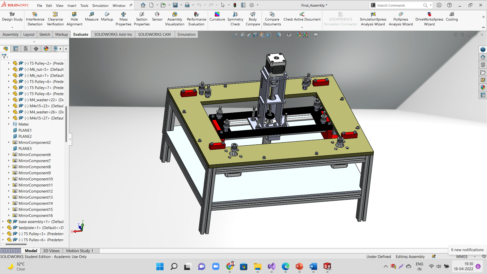 |
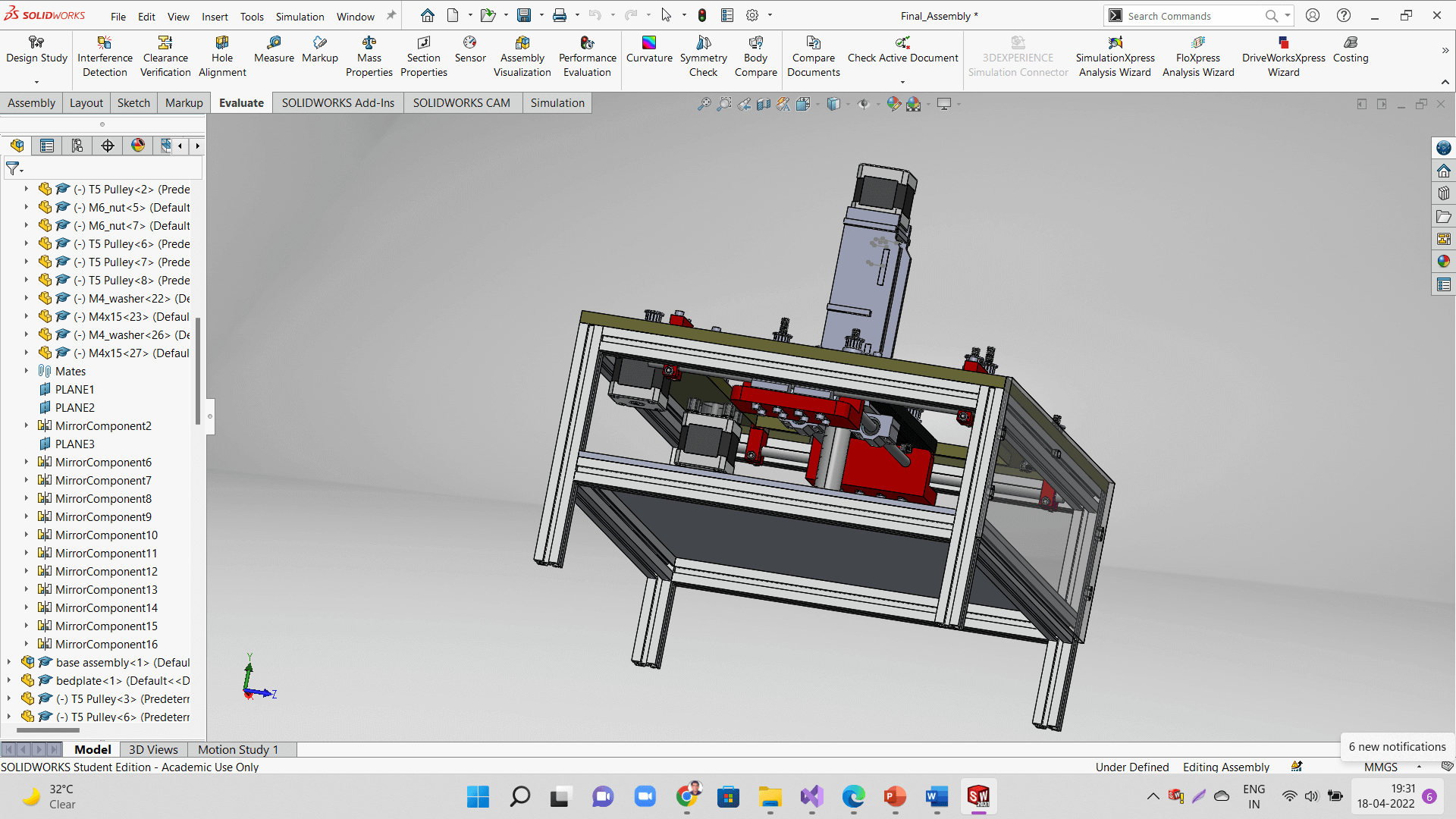 |
Below is an animation we captured from the assembly file.
Following are the sub-assemblies of the machine.
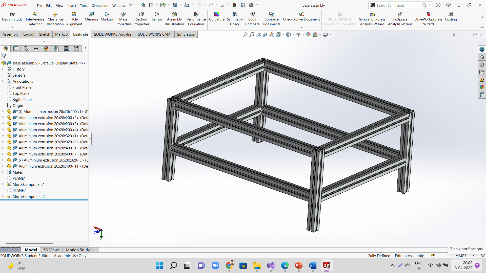 |
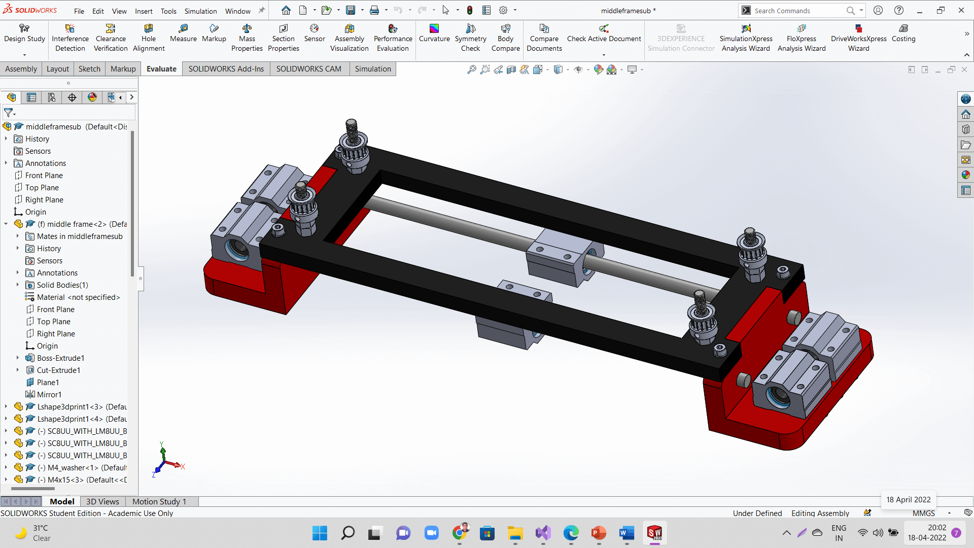 |
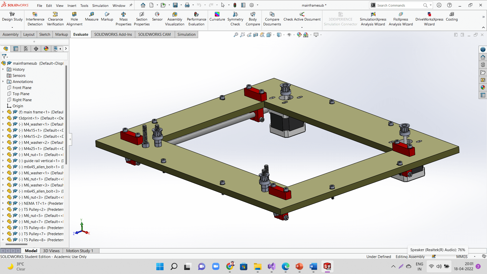 |
 |
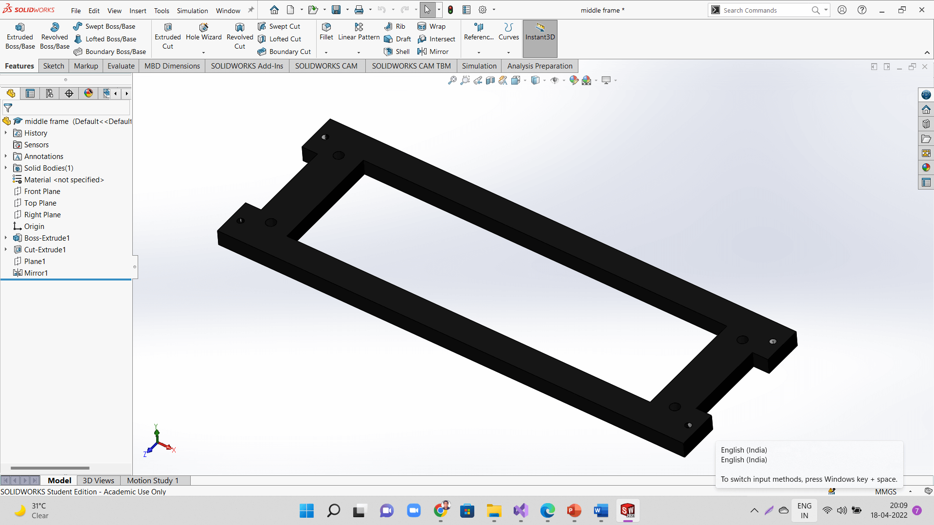
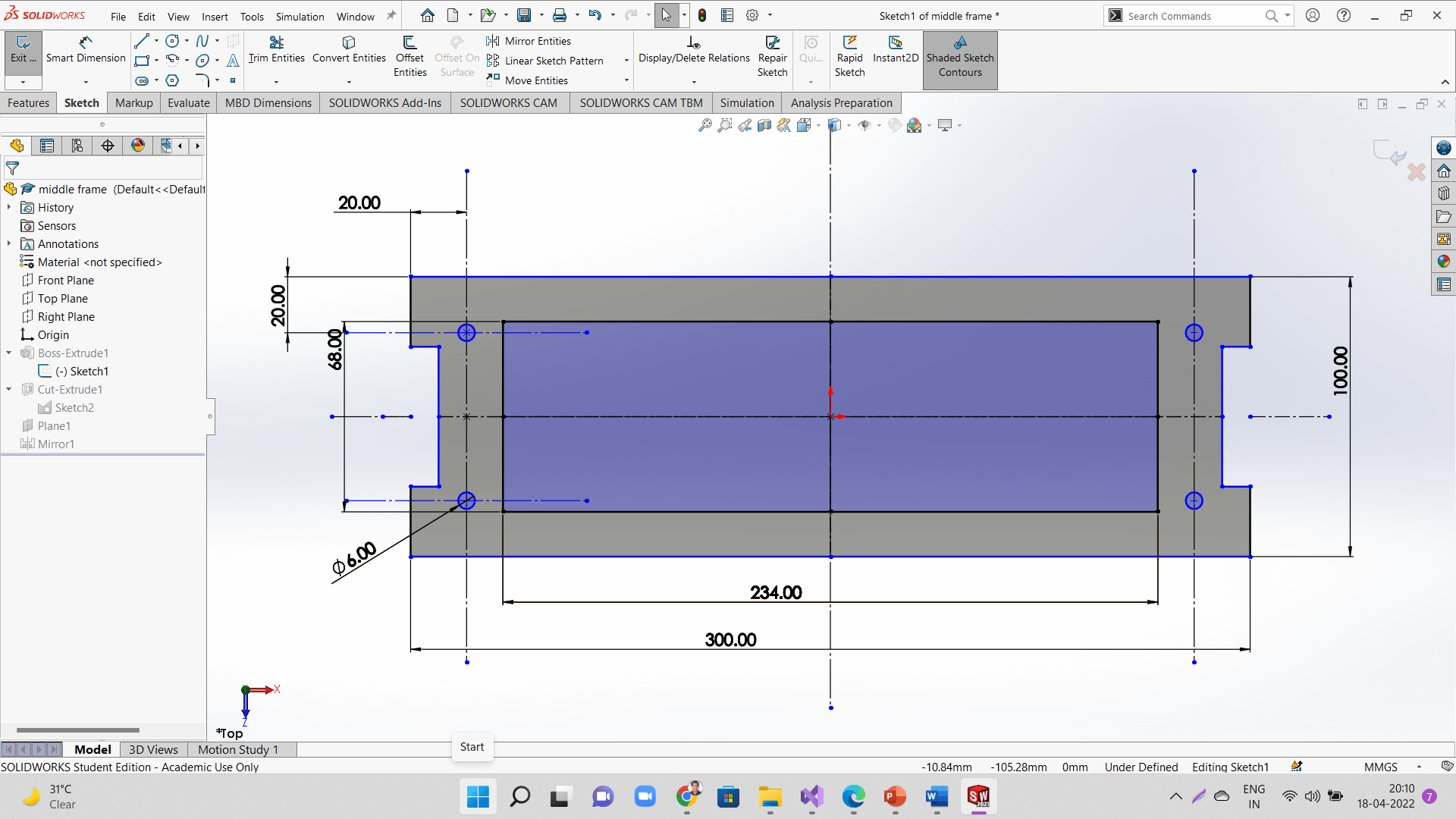
Following are the 3d models of sketches of some of the major parts.
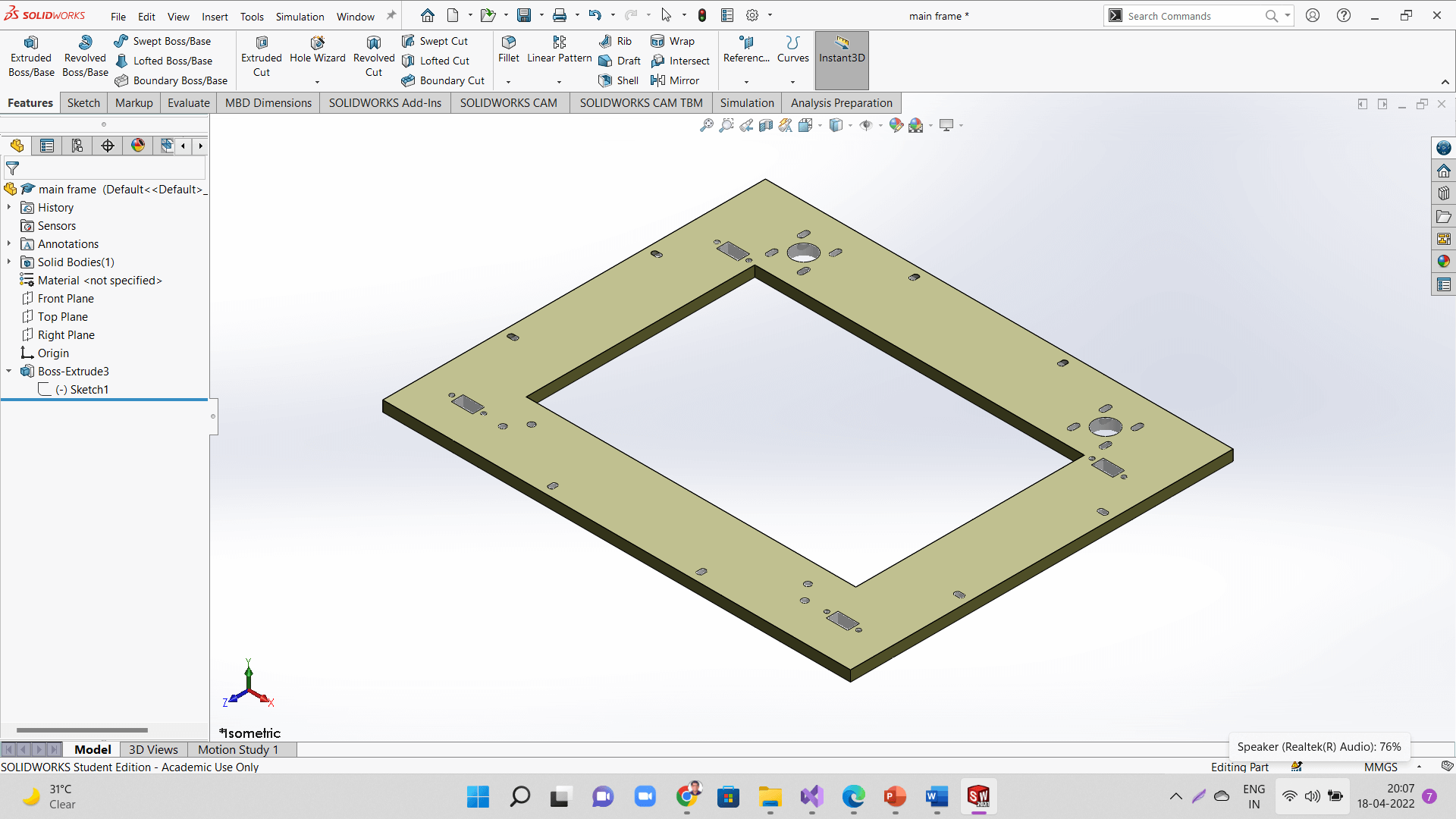 |
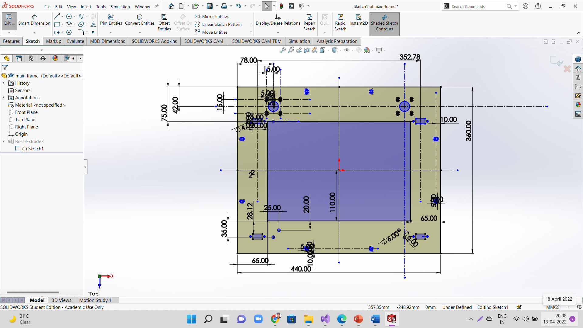 |
 |
 |
 |
 |
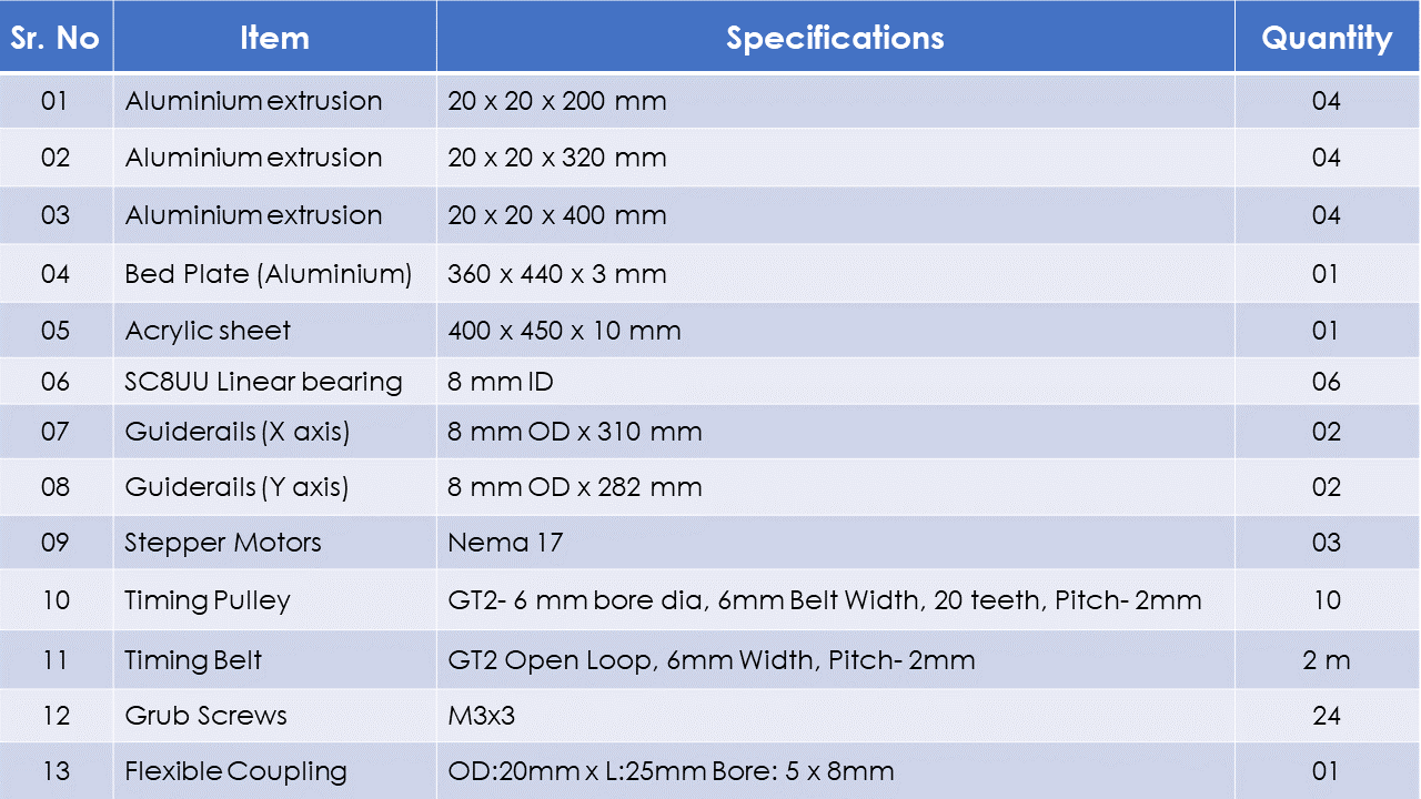
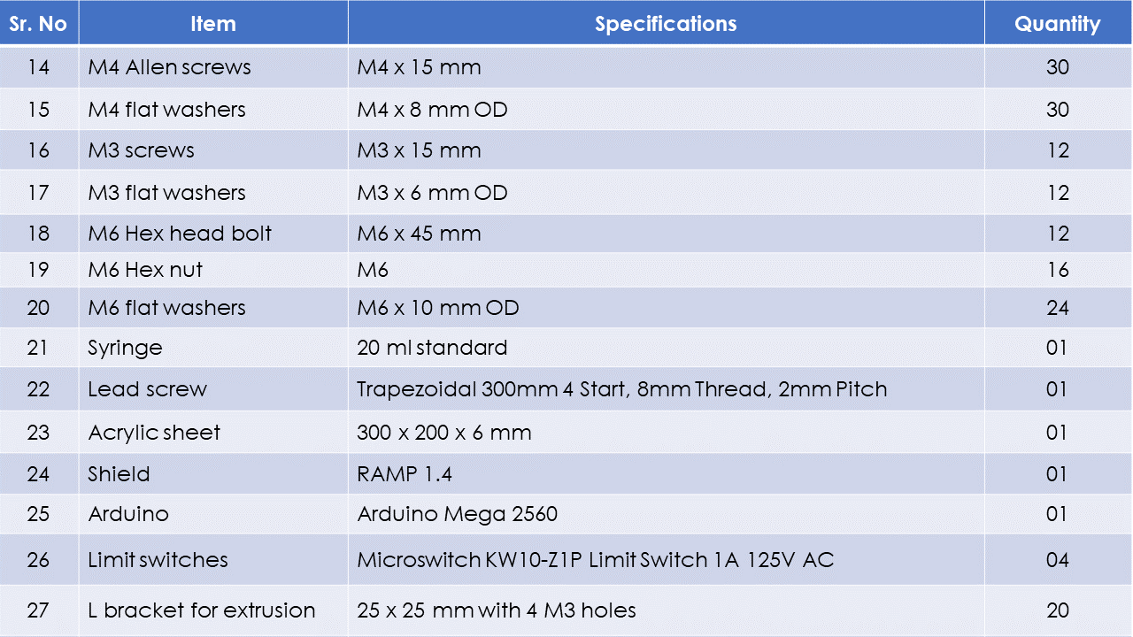
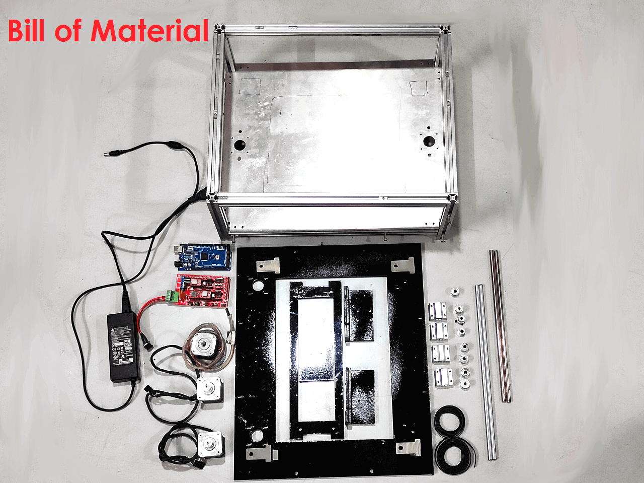
Below is our engineering and manufacturing Bill of Material of our entire machine. We did not include wires and power supply accessories in to the BOM.
Bill of Material:
 |
 |
Fabrication
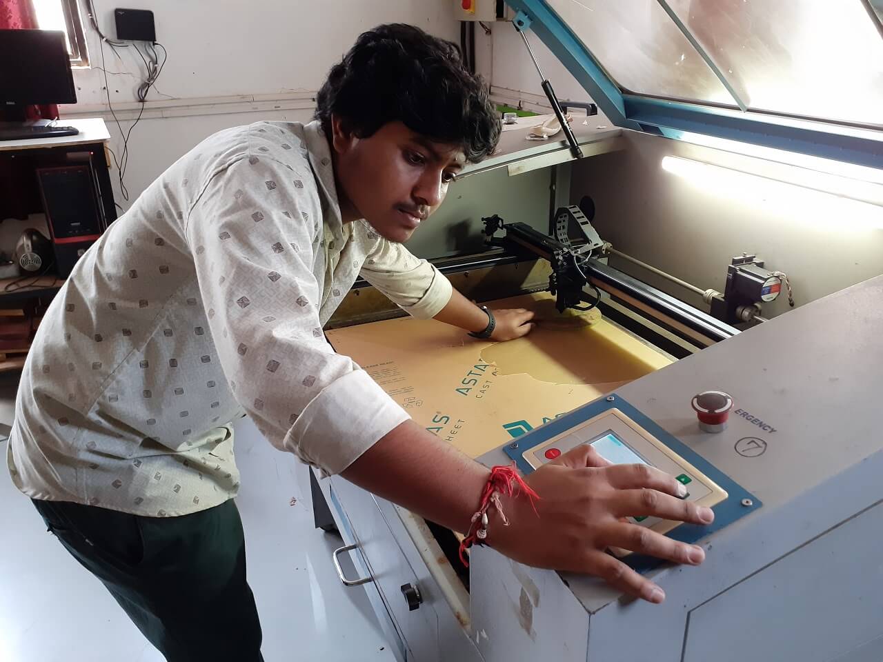
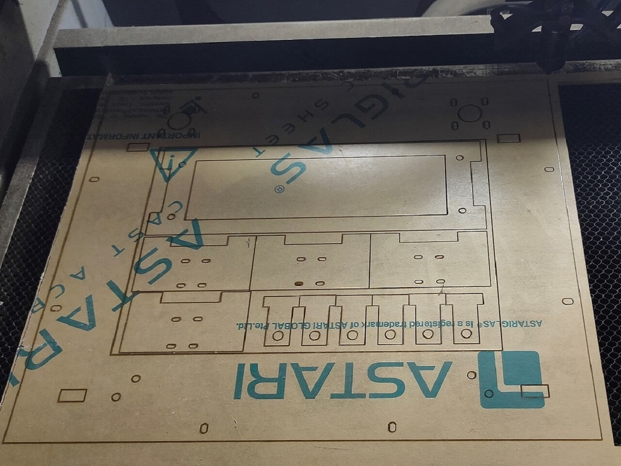
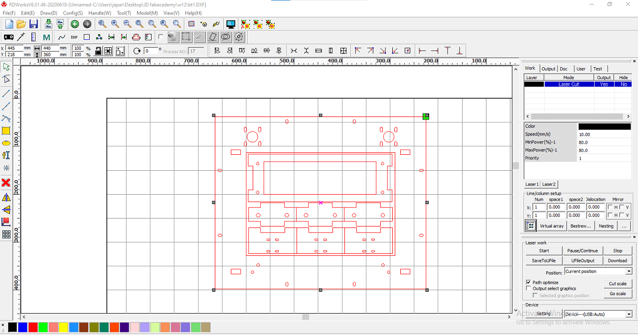
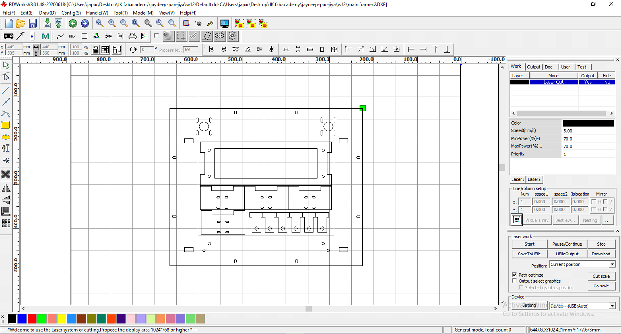
1. Laser Cutting
We laser cut the main frame, middle frame plates. We also had cut the L shape bracket and T-slot brackets using the laser cutting.
 |
 |
 |
 |
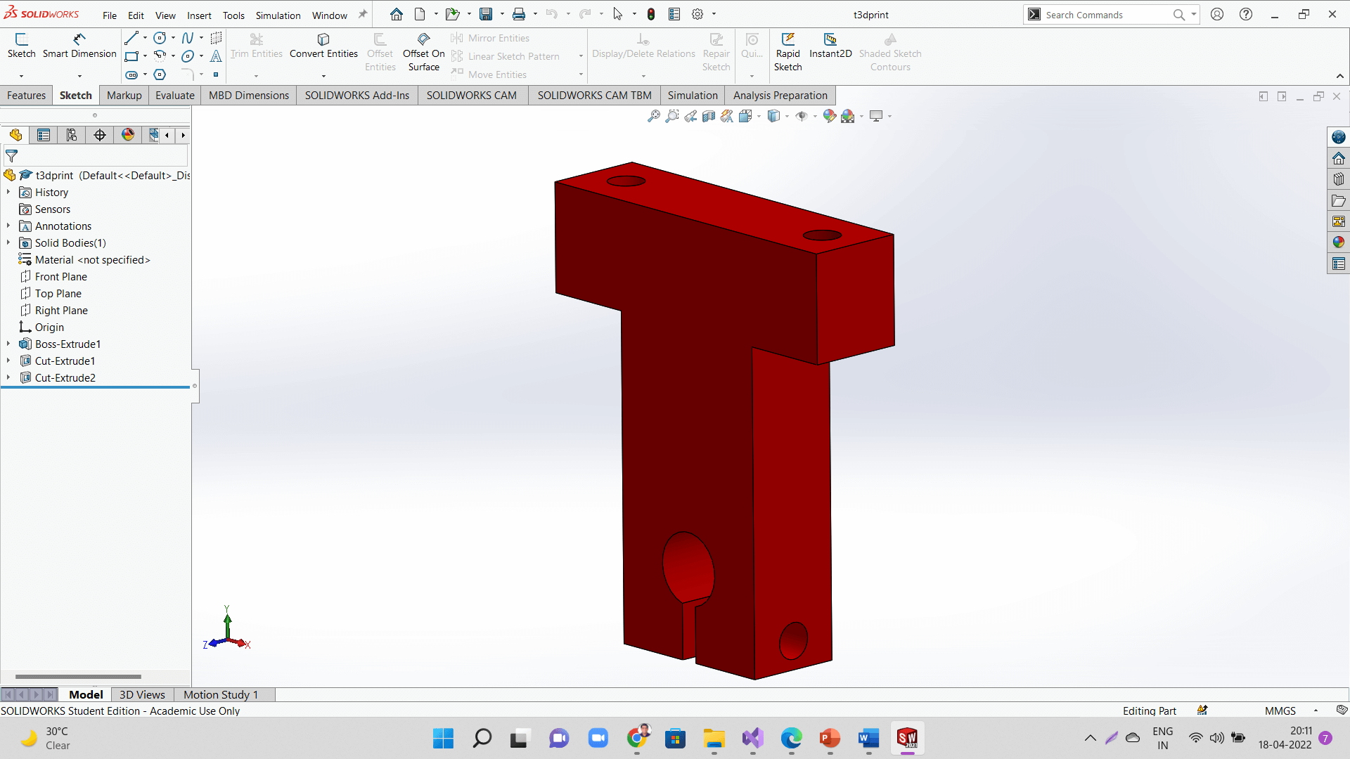
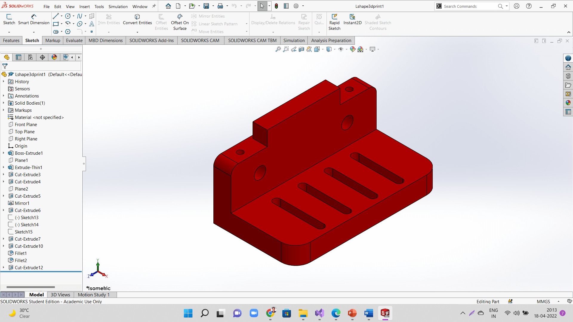
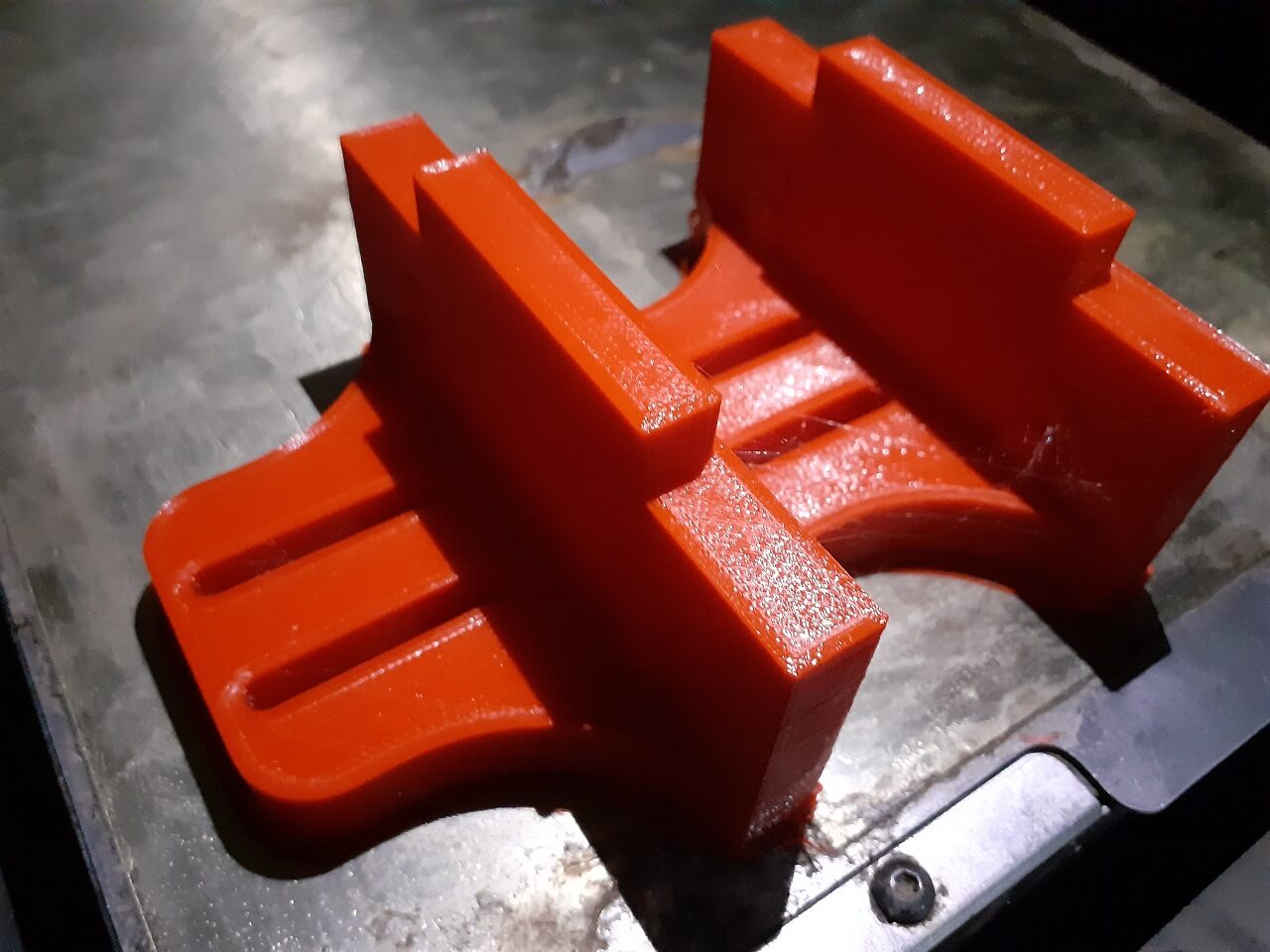
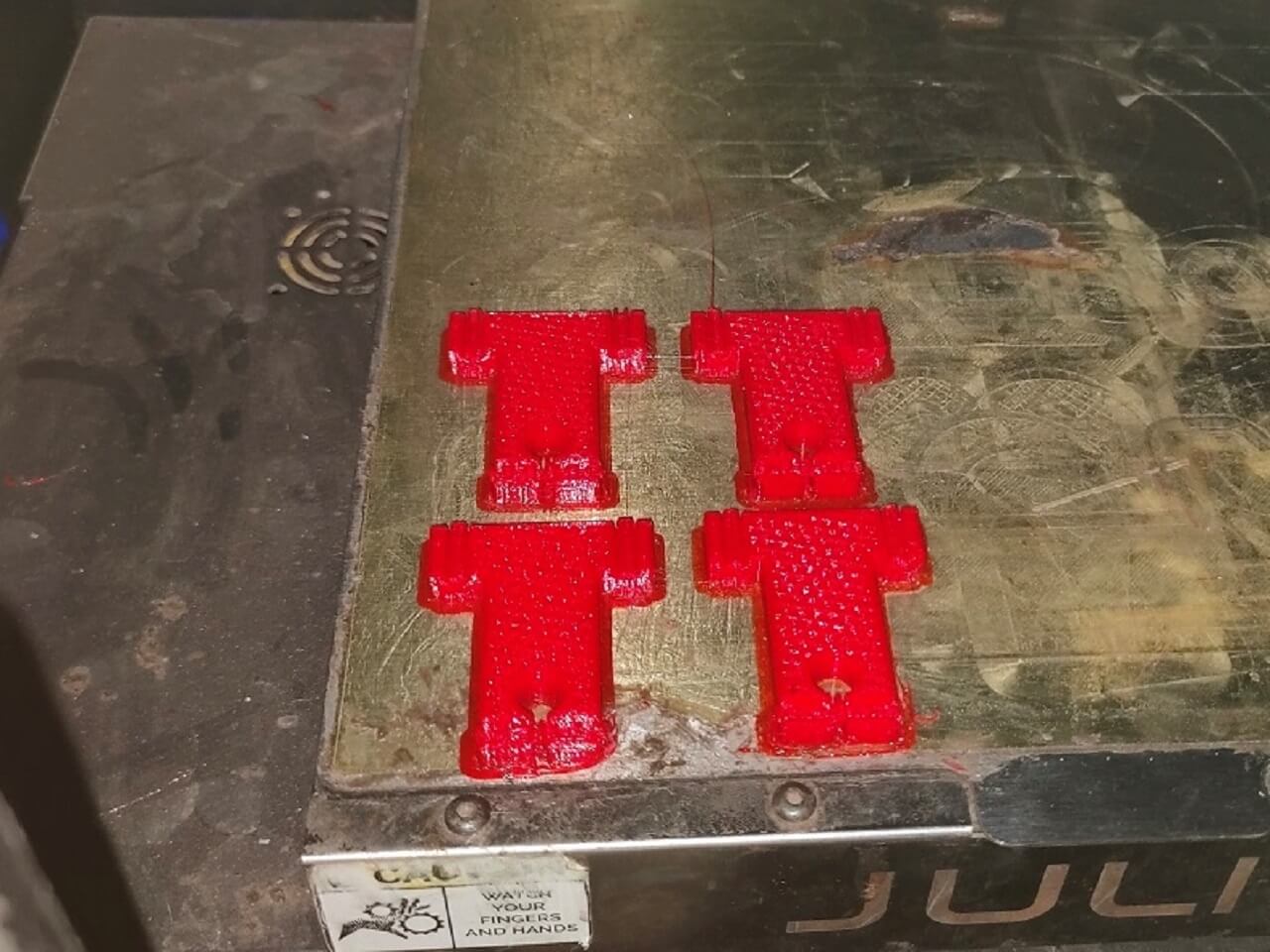
2. 3D Printing
We 3D printed the L shape bracket for mounting linear bearings for Y axis and also T holders for guiderails after we found issues in assembly later. We have mentioned the issue later in the document below.
 |
 |
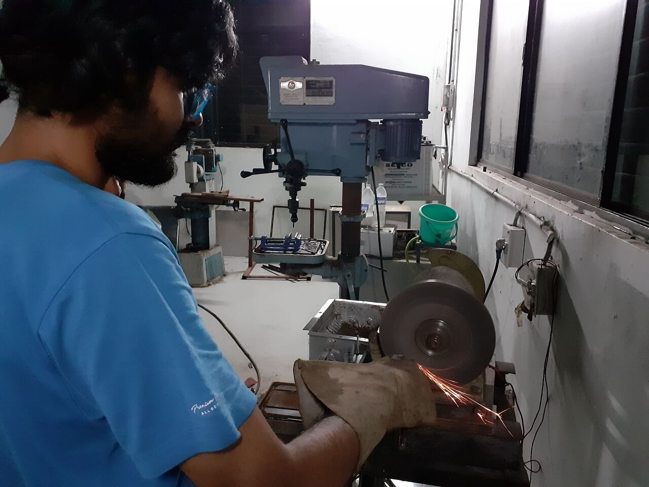
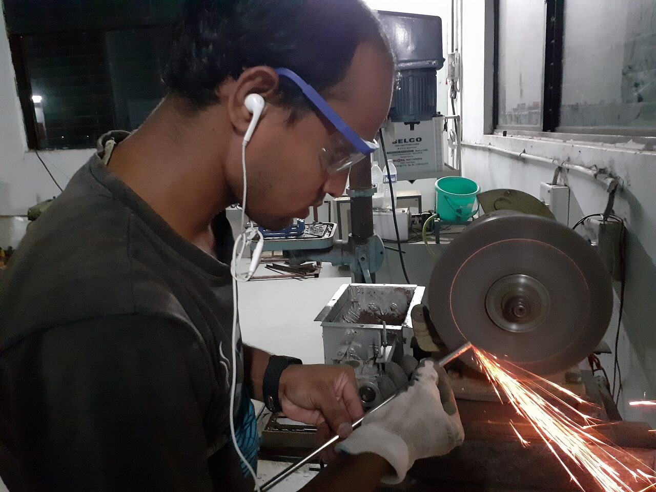
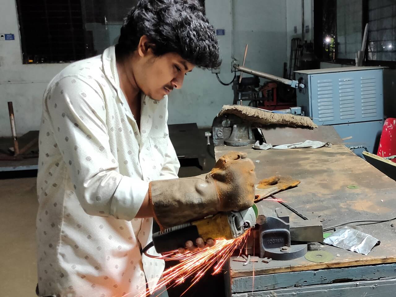
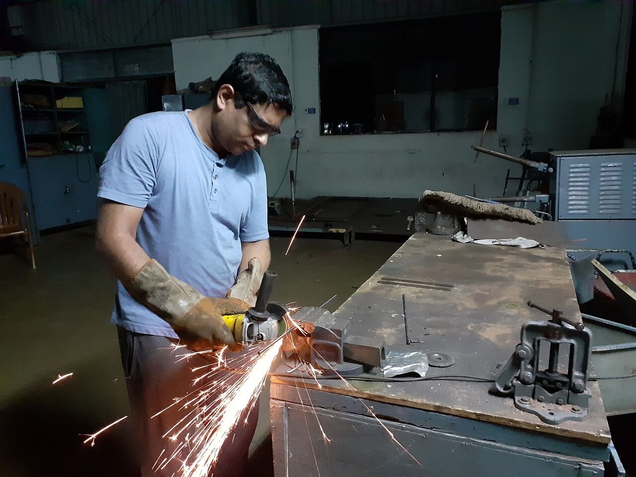
3. Cutting and Grinding
We needed to cut the guiderail shafts and one aluminium extrusion as per our design, we used a power cutting and grinding tools for these operations, we also provided a chamfer on the edges on guiderail shafts.
 |
 |
 |
 |
Assembly
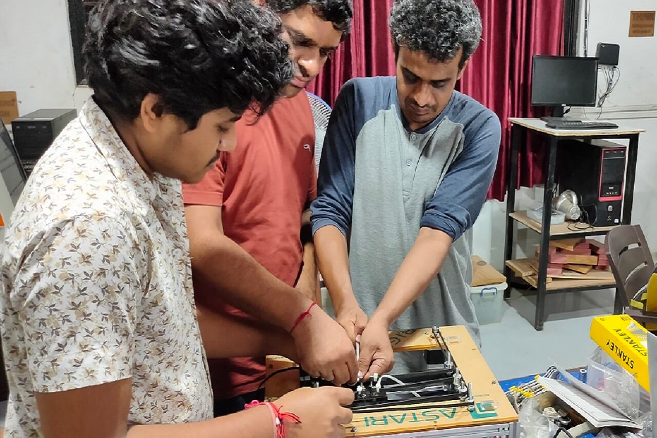
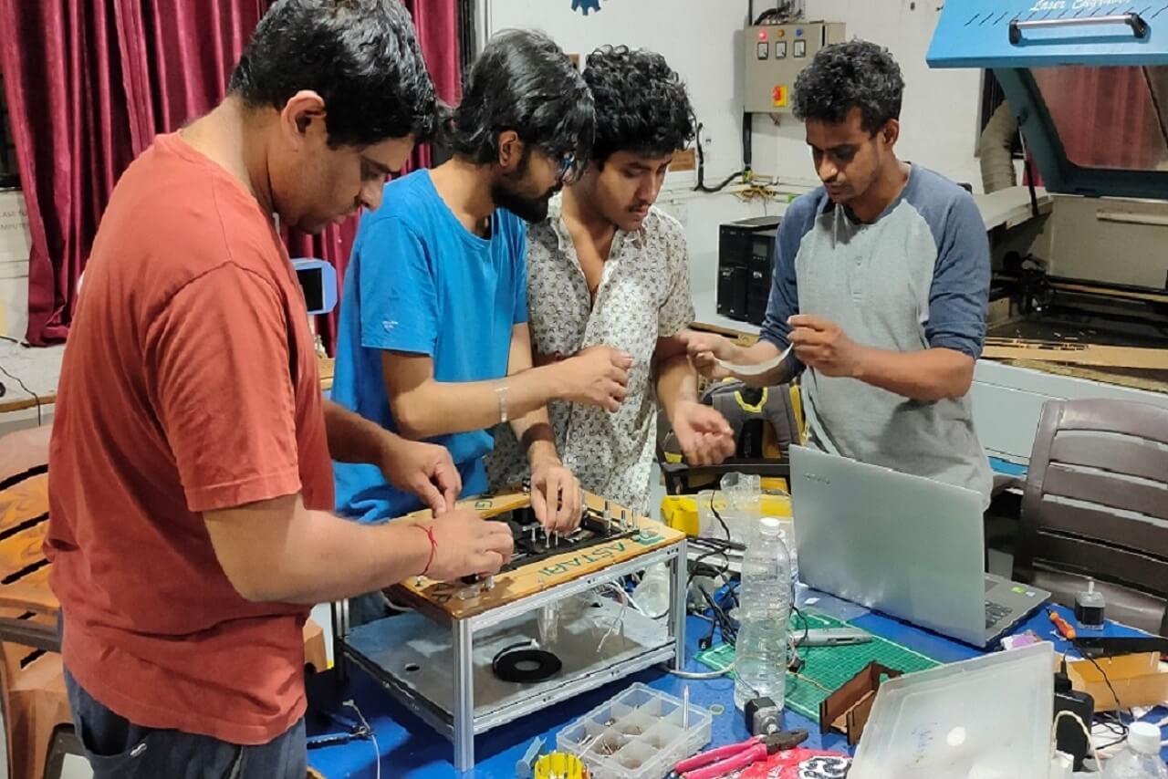
Once all the parts were in place (either purchased, laser cut or from our lab inventory), we started to assemble the machine. Following is a picture of all the material in place.
 |
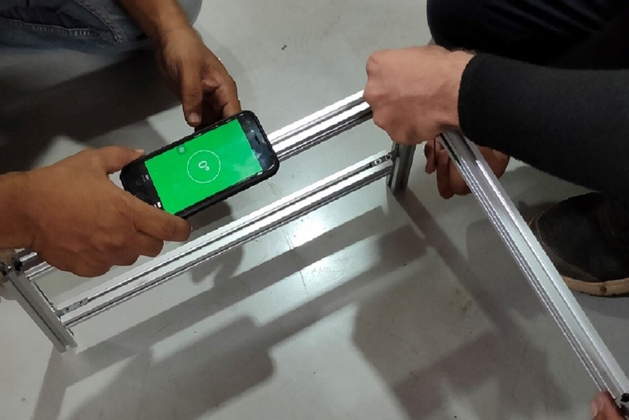
We started with building the base frame with the aluminium extrusions we had. We levelled them as we were assembling them. We started assembling the main frame sub-assembly and middle frame sub-assembly.
 |
 |
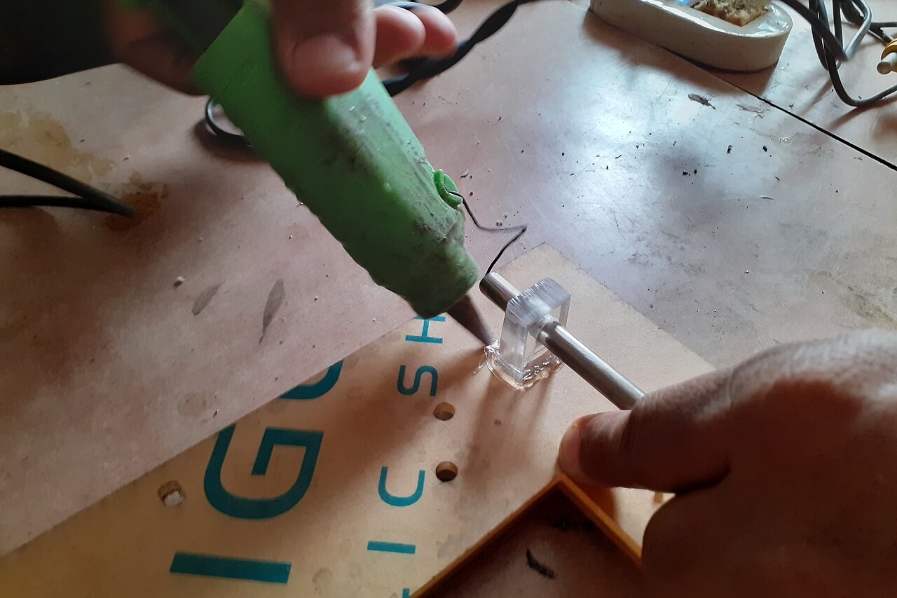
The T-slots we had cut on laser were not cut as per the designed specifications. So, they were not sitting in place. We fixed them using the glue just to check if the assembly works. This was not a permanent solution though.
 |
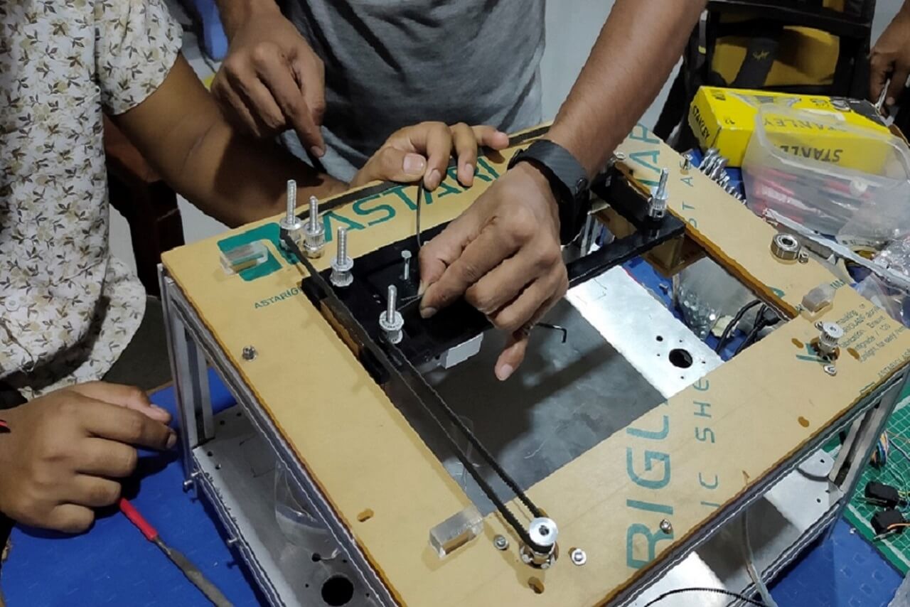 |
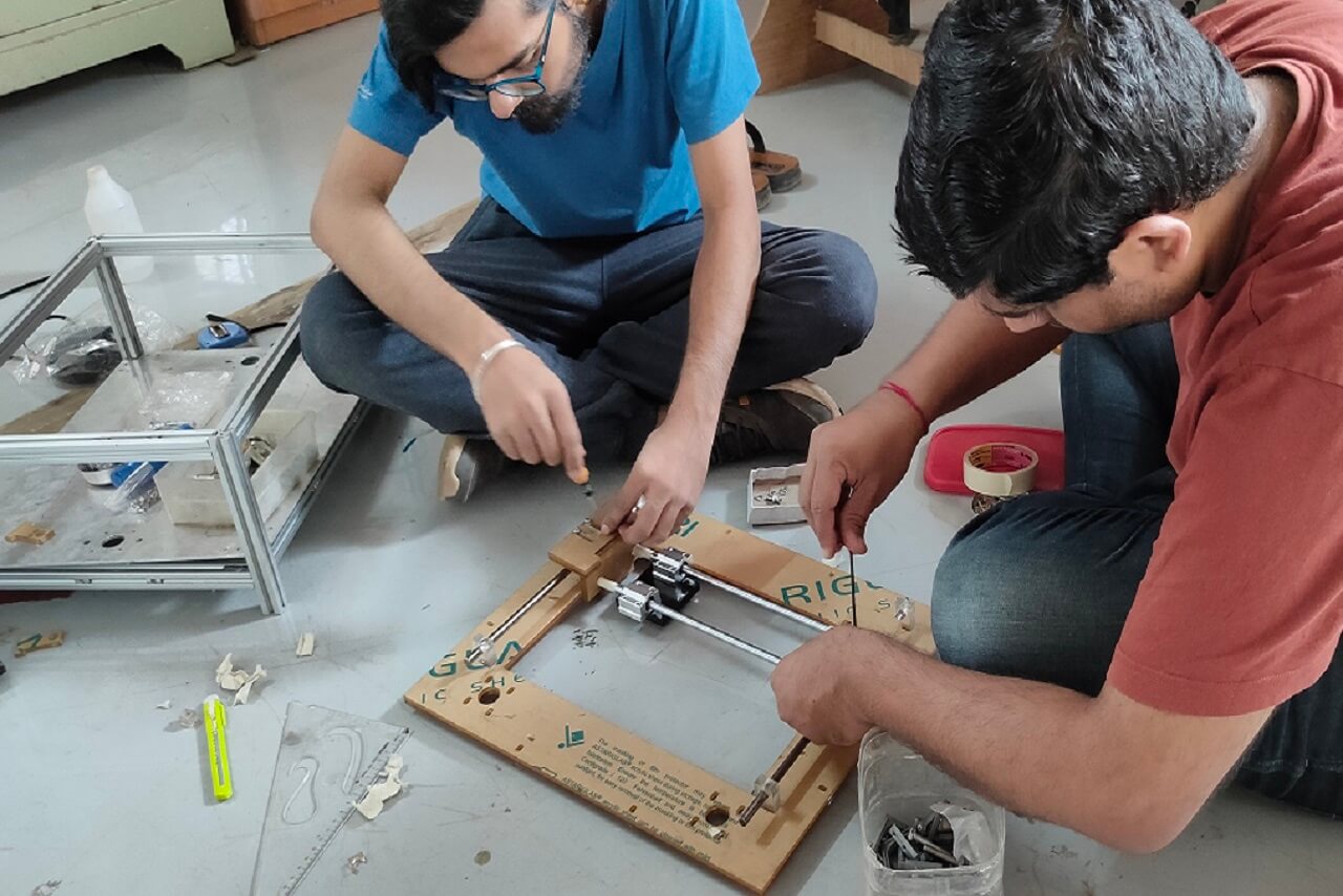
We started assembling all the parts to the assembly, like stepper motors, pullies, timing belt, hardware, etc.
 |
 |
 |
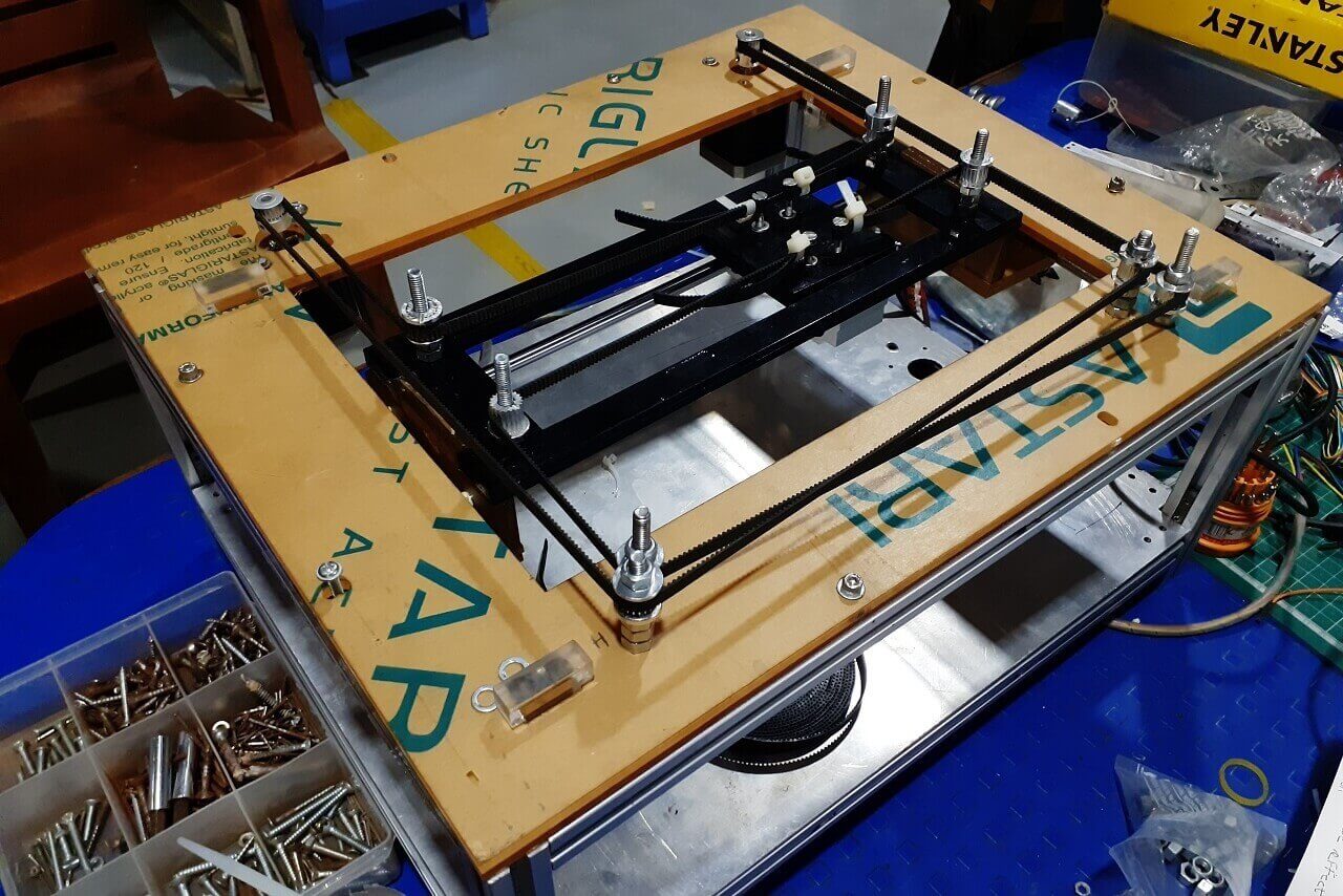 |
However, during the assembly process, we had fitment and alignment issues with T slot brackets that hold the guiderails along the Y axis, L shape bracket that hold the linear bearings. The T-slots cut by laser were not having proper press-fit and the L-shape bracket was not at perfect 90 degrees. Apart from that these guiderails had single linear bearing each, so the movement of the mechanism along the Y axis was not happening smoothly, it was wobbeling too much.
So we decided to go for 3D printing of T brackets for holding guiderails and L bracket for mounting linear bearings. Also we added an extra bearing each to the Y-axis guiderails as shown below.
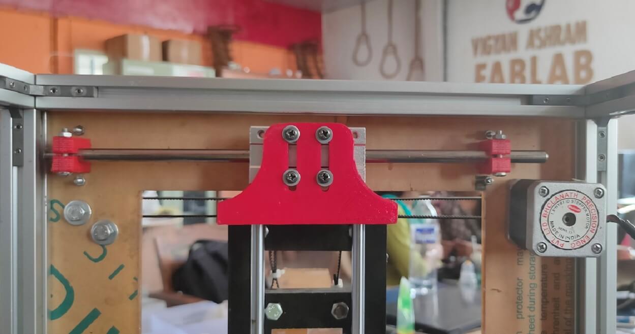 |
This major hurdle in building our machine was thus removed successfully after implementing this solutions. The mechanism was working perfect now.
Actuation
After we replaced these parts and adding extra bearings, we re-assembled all the parts again and we were able successfully actuate the mechanism as shown in the video below. It works pefrectly fine on all 6 different movements.
Electronics
Vrushabh and Devesh took responsibility of electronic and software designs for the machine, out of, which Vrushabh focused on the electronic part of the machine that includes testing and connecting various electronic parts such as stepper motors, drivers, shield, controller board, end switches, cables, etc. and integrating all of this with the software part of the machine.
A. Electronic Hardware
Selection of the electronic components:
We refered diferent CoreXY based CNC plotters, they all have used the below components specifically when using Marlin as a firmware-
- Stepper motor
- Stepper motor drivers
- Driver shield
- Control board
- End Stopper switch
- External power supply
Selecting the stepper motors and stepper drivers:
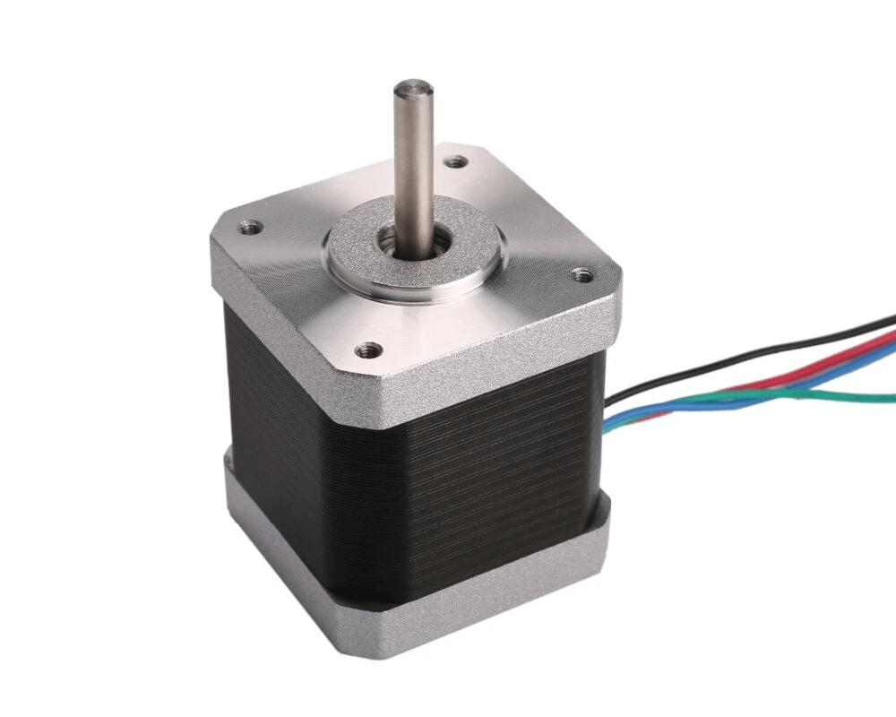
Based on the requirements of the mechanical design of the machine, we selected Nema 17 stepper motor with 5.5 kg-cm torque to drive the machine axis. We selected two such motors for running XY axis in CoreXY and one for extruder.
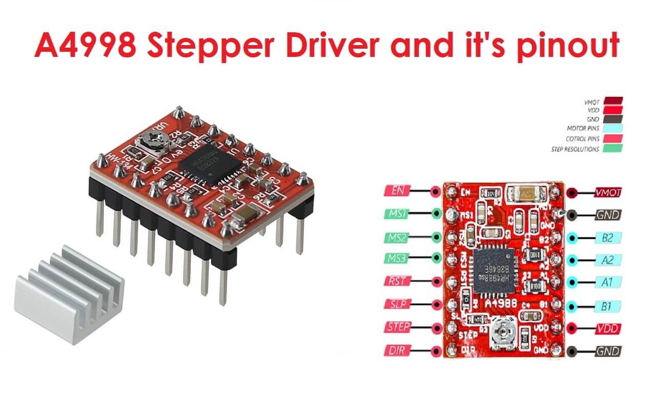
For running the stepper motors, we required stepper drivers. For, which we had multiple options. However, considering the driver configuration availability in Marlin firmware and the inventory we had in our lab, we went with A4988 as a motor driver.
 |
 |
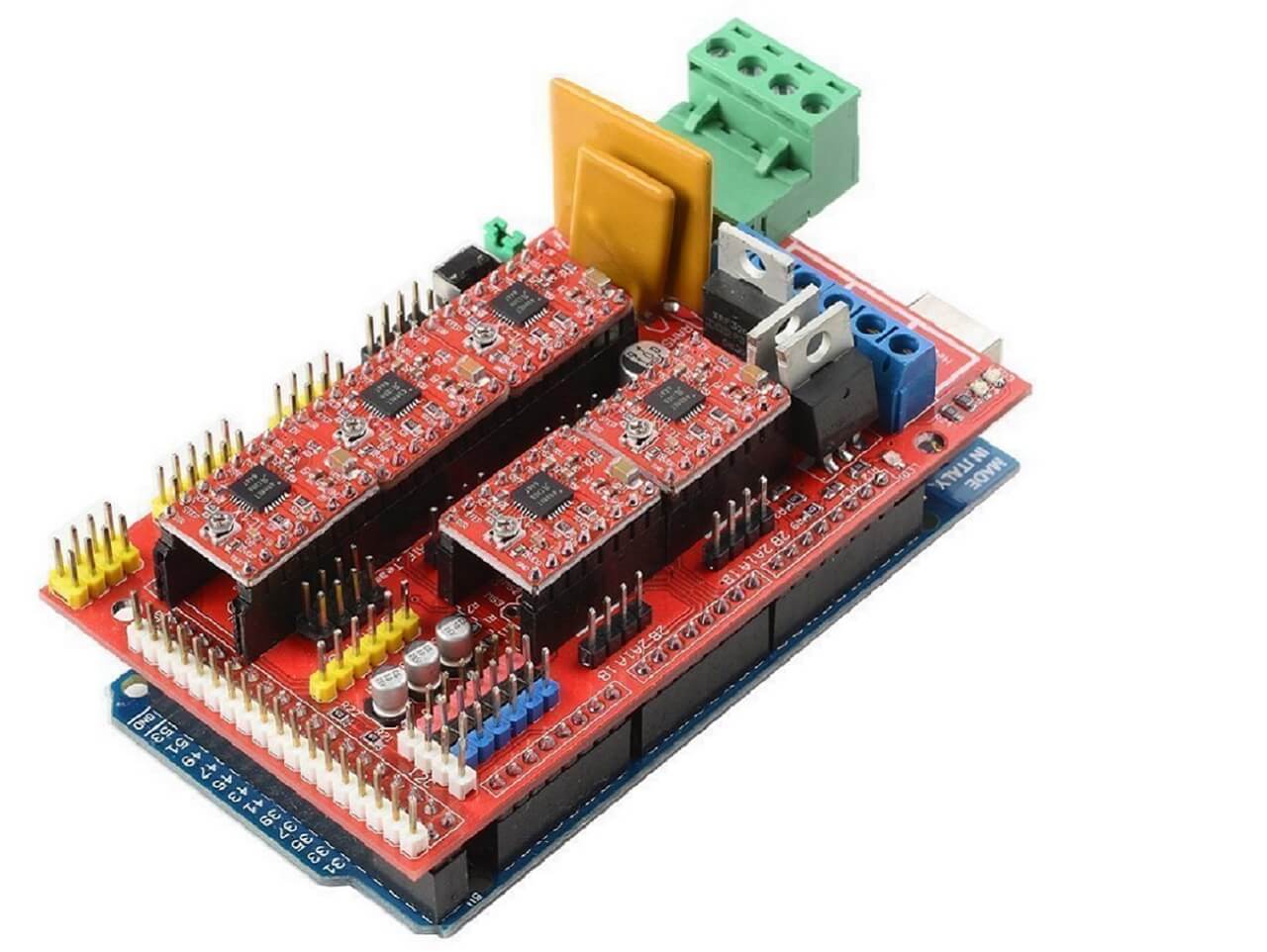
Selecting the CNC stepper driver shield and controller board:
There are so many types of CNC stepper driver shields available, out of, which we had in our lab, Arduino CNC V3 shield, Ramp MKS 1.4 V, and Ramp 1.4 CNC shield. We selected Ramp 1.4 CNC shield because of its strong community support and availability of multiple such shields in our inventory.
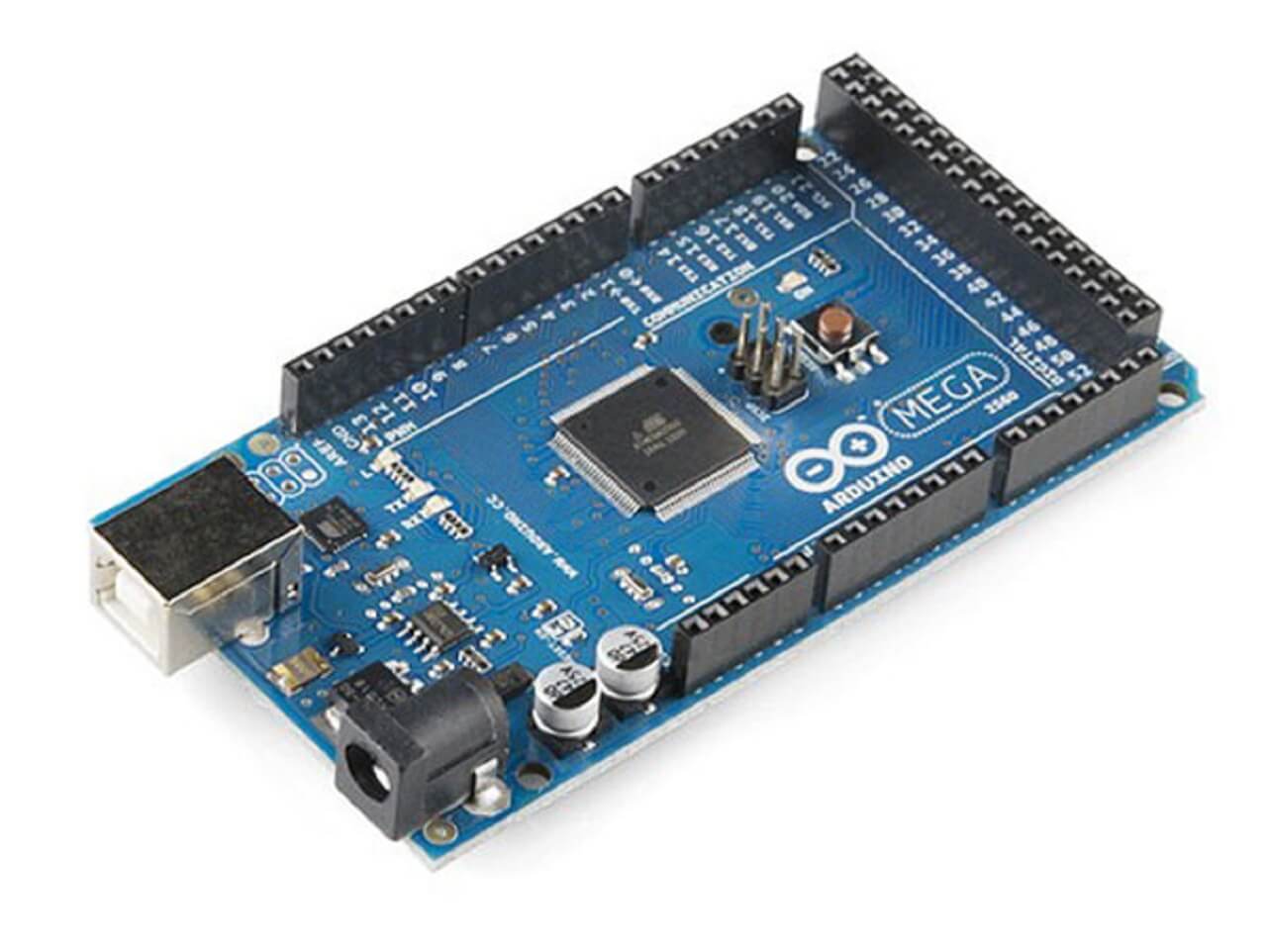
As the Ramp 1.4 boards are built for Arduino Mega 2560, we had no other option for selecting the controller board than Arduino Mega 2560.
 |
 |
Selecting the power supply:
As per the requirement of current consumption and voltage requirement for electric components for our machine, we chose 12V 5A power supply for powering up the machine.
Testing of electronic components:
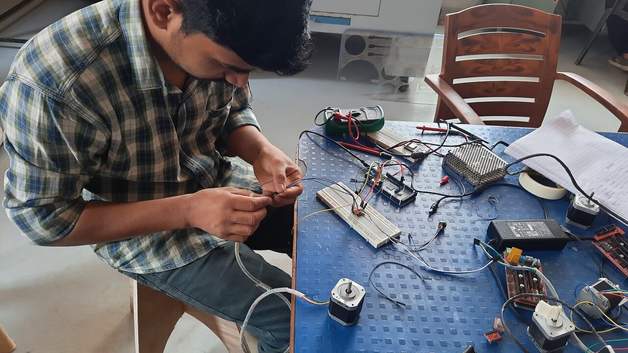
1. Testing stepper motor and stepper motor drivers.
We wanted to test the stepper motor before setting up our electronic for our printer. As we were going to use Marline firmware and it is not configured yet, so we decided to test the stepper motor first. We started with testing individual stepper motors for, which we referred the blog from last-minute engineers. We tested all the motors and drivers and they were working fine.
 |
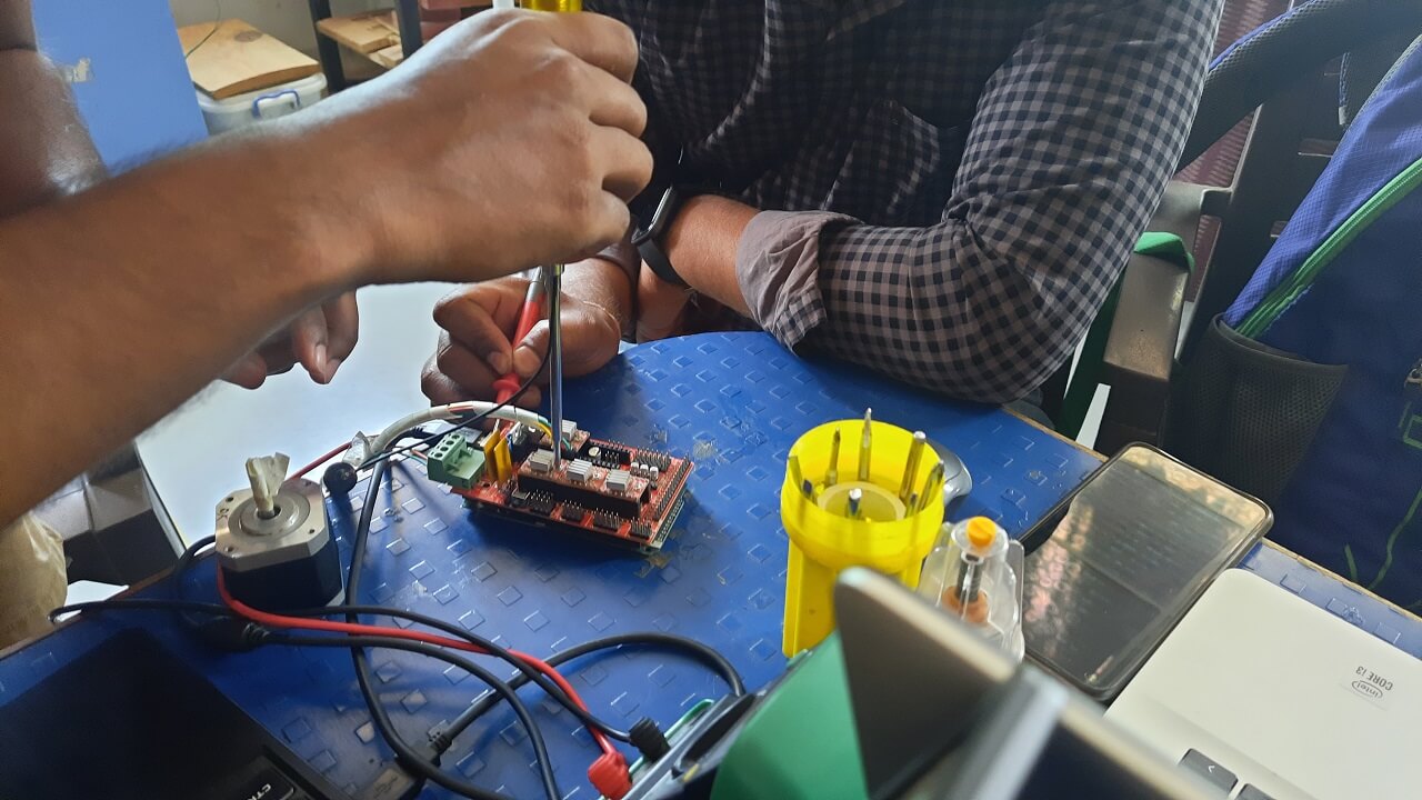 |
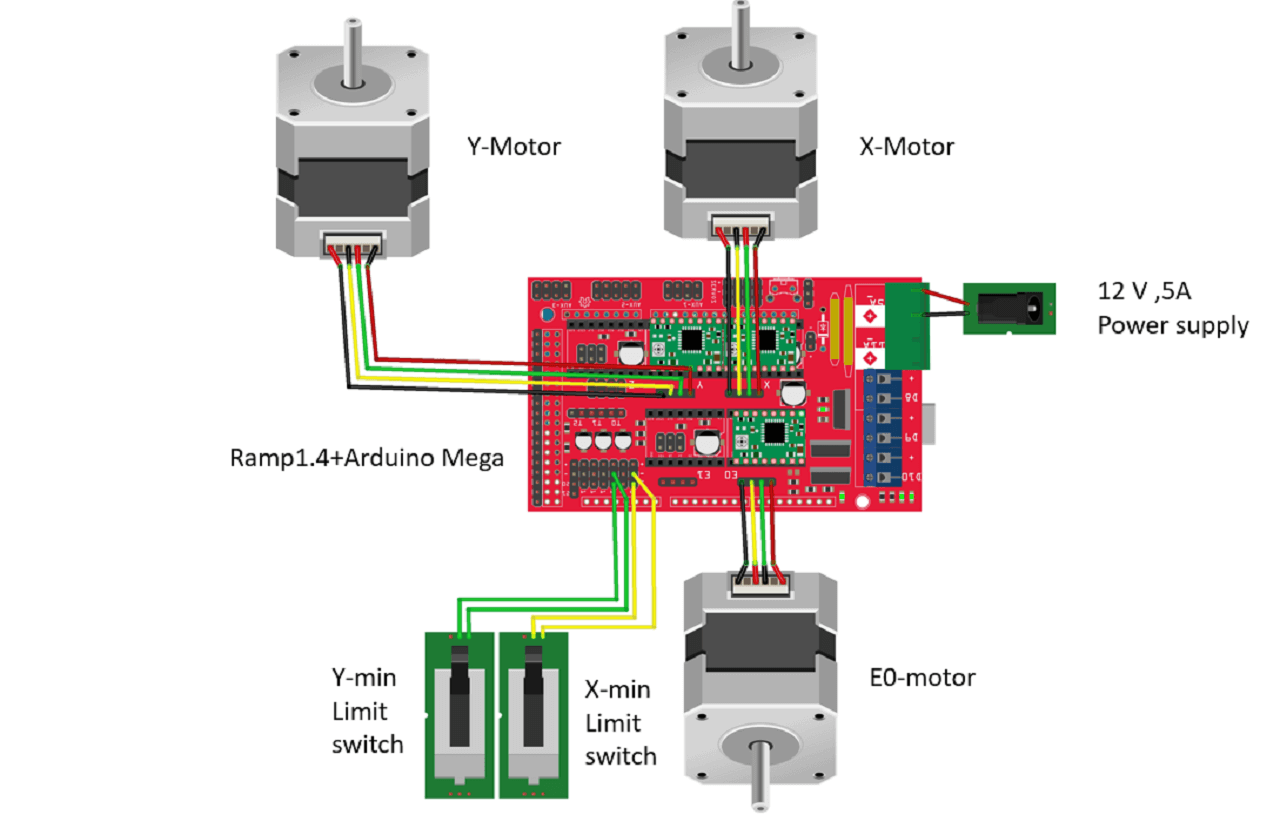
2. Testing stepper motors with Ramp 1.4 shield.
After testing motors individually, we tried to run them through Ramp 1.4 shield. For that, we referred this site for more details on Ramp 1.4. We referred this site for understading Ramp 1.4 connections.
 |
we assembled the motor drivers on the Ramp, attached the 12V 5A supply to the board and set everything ready to test. We used the same test code to try to run the motor on-ramp shield after checking the dir and step pins from the schematic diagram of the ramp board for the X-axis motor.
To know the pinout for X-axis, we referred this site for more details. For X axis- it is A0 and A1 for dir and steps respectively. After we made the connections, we uploaded the code but it did not work, the motors did not run. Then we checked for the power supply for Ramp board, arduino mega connections and also did the cable output continuity testing. But the motors did not run.
After several trials to run the stepper motor on Ramp 1.4, finally we found that Ramp library is missing in the arduino code and it needed to be installed as well. We got the Ramp library from this site. Sign in on github in case the page shows 404 error. We used the arduino code from this site and made custom changes to it according to our requirements to run all the motors. Sign in on github in case the page shows 404 error. All these steps helped us in running the steppers using ramp board successfully before configuring the hardware with Marlin.
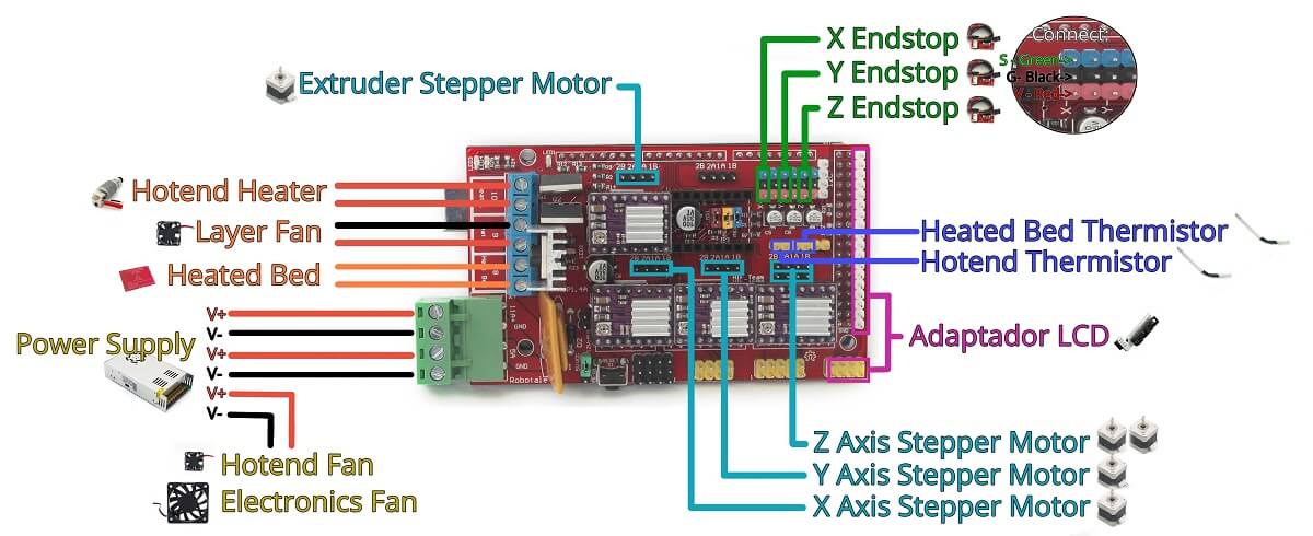
3. Assembling limit switches and circuit diagram.
This is our final circuit digram of the electronic on our machine. We will discuss more about setting home position of the machine using limit switches in the subsequent sections below.
 |
4. Connections and routing on the machine.
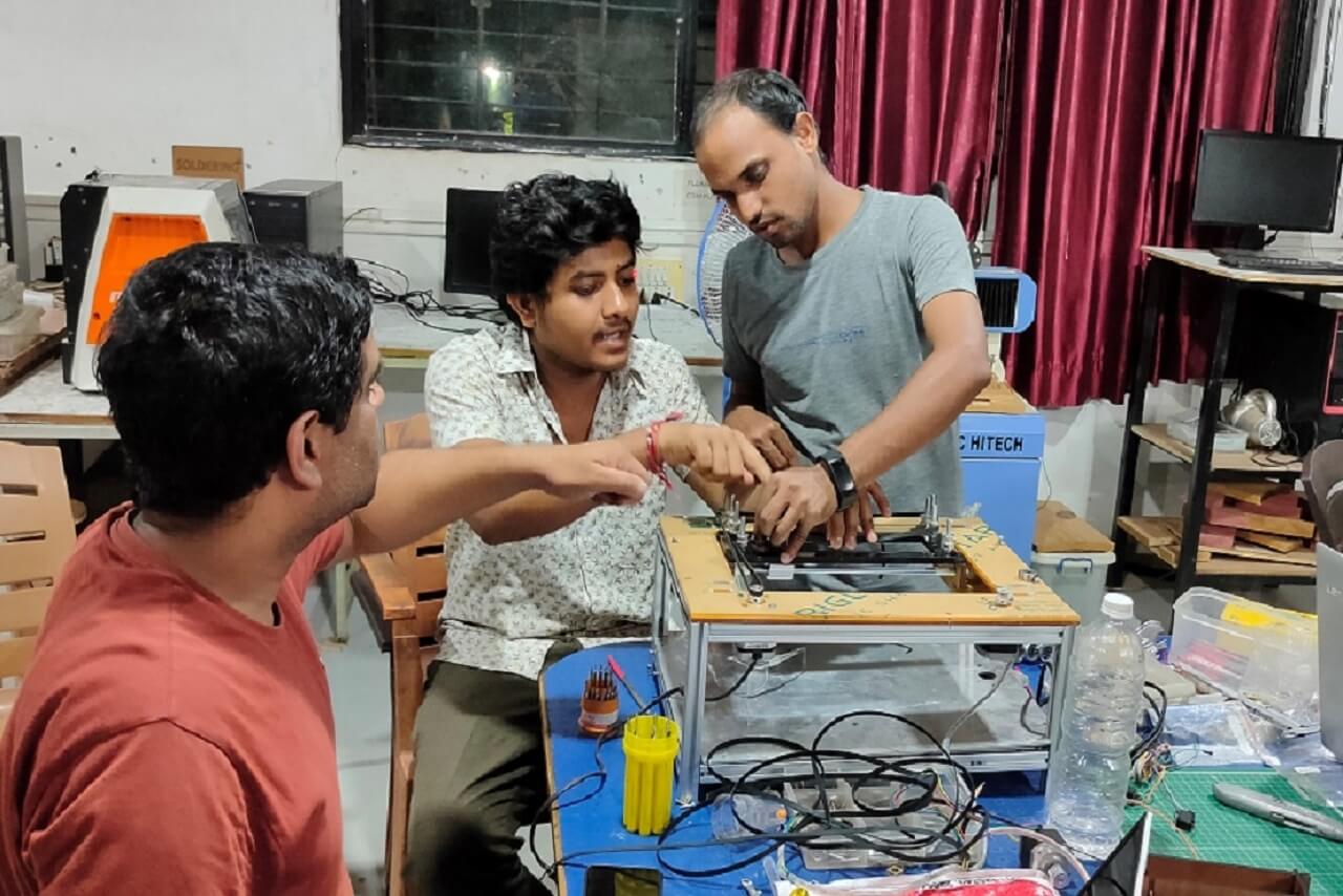
For final testing of machine, we assembled all electronic hardware components on the machine as shown in the image below. We then uploaded the marline code in Arduino mega board. Important note: Remove the ramp shield during uploading the code.
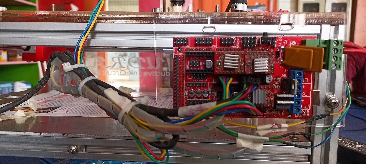 |
B. Firmware and Interfacing
For final testing of machine, we assembled all electronic hardware components on the machine as shown in the image below. We then uploaded the marline code in Arduino mega board. Important note: Remove the ramp shield during uploading the code.
Selection of the Software:
After our brainstorming session, our group came to the conclusion to use Marlin as a base firmware for our printing machine since it is hugely popular and it has a great support from the community. Read more about Marlin here.
Selection of the firmware enabled us to focus only marlin for a couple of days and gave us a headstart. Marlin firmware was spun-off in 2011 for Reprap and Ultimaker by Erik Zalm. It is the perfect firmware for our needs highly customizable and easier to compile.
The best part is that it still supports older ramps shields which was available in our lab. The downside is that the code is a bit heavy and the compile times are higher than expected. After making some changes to the code the user has to wait for almost 10 minutes to compile and upload the code to an Arduino Mega development board.
Though there were other options for the hardware selections we were just beginners and want to try something on already test hardware for better support. The RepRap community is huge and has alot of fixes for the issues it was like a treasure trove of knowledge.
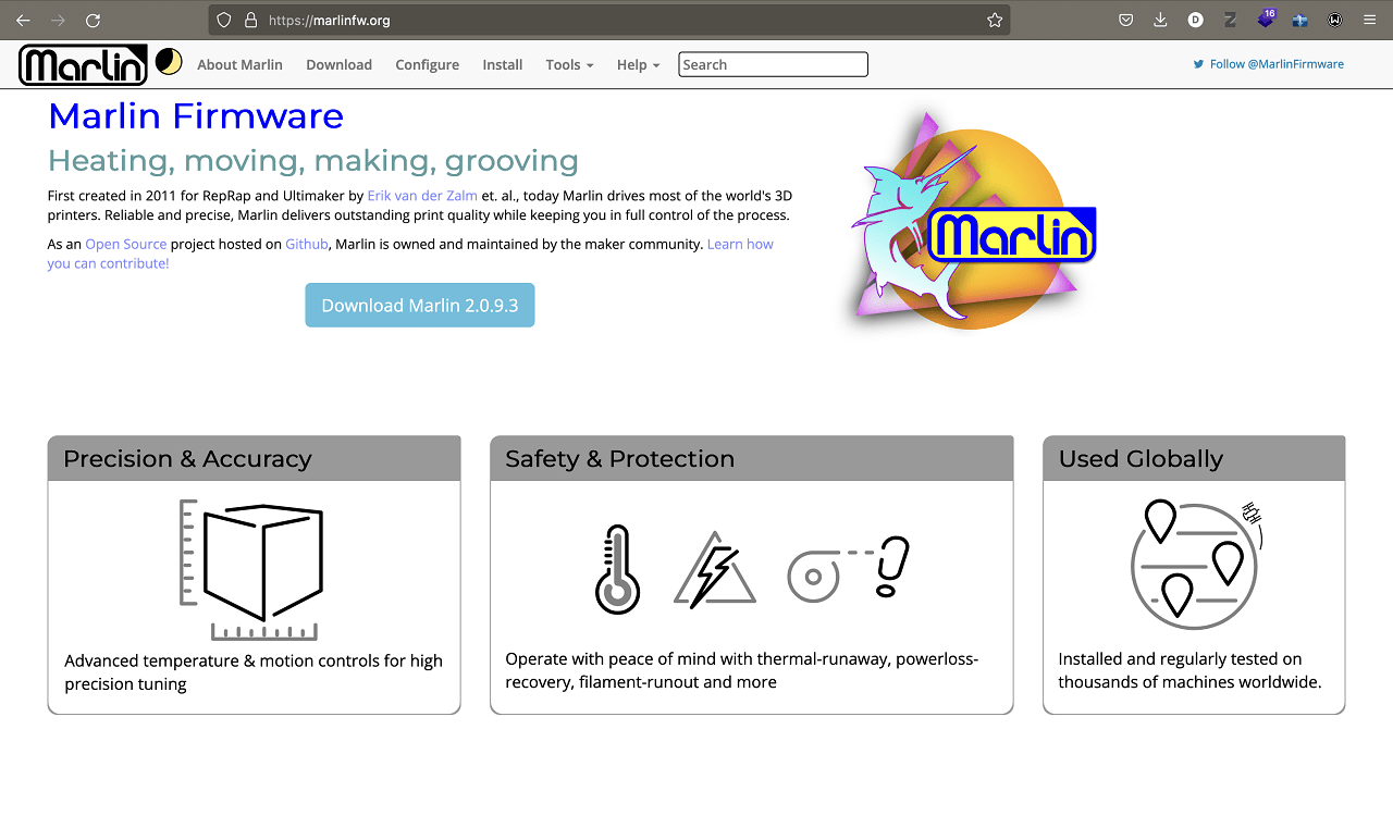 |
Downloading the firmware:
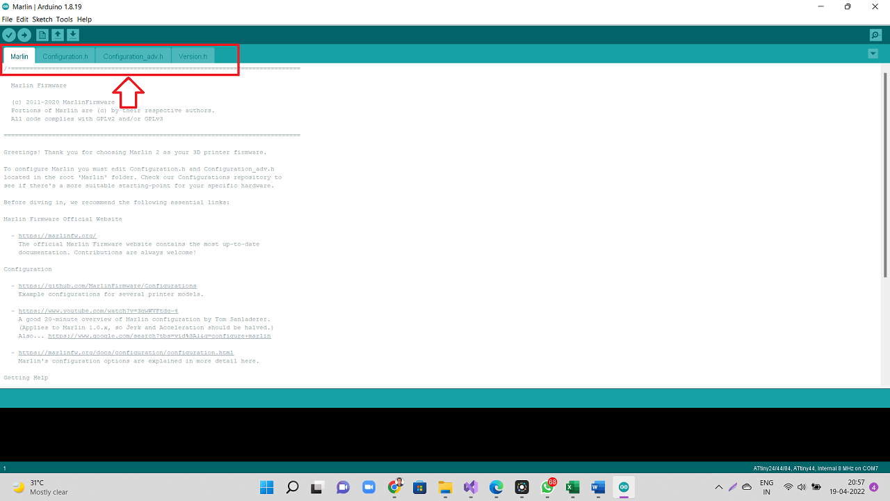
Go to the Marlin Website. Follow the steps involved and choose Marlin Ver 2.0.9.3 while downloading in the downloads page. Your marlin files will appear in the downloads folder. Extract the folder and locate the Marlin folder in it and search foe Marlin.ino file which opens up in Arduino IDE.
When the file opens, there will be a total of four files opened simultaneously, one of them would be Configuration.h and another is Configurationadv.h. These are the files that contain the code for marlin firmware. Edit the necessary parameters and boom your barebone firmware ready.
 |
Editing and updating the firmware:
Customizing the marlin firmware was easy but there were some bits that even we didn't understand like giving the temperature setting for the extruder etc.
Marlin is highly customizable but we had to seek help of one of our instructors initially to get the code running as he was the one, who recommended us to use Arduino IDE to compile the firmware. In the end after two days of compiling and debugging the firmware was ready to be tested on the assembly. Below is the video of us testing the software and the hardware initially.
Automating the machine:
After editing the firmware and configuring pronterface, we did initial trials running motors on the machine and check if our automation is working perfect. We gave small steps to each motor and saw the motors moving and thus moving our CoreXY mechanism in desired directions through automation.
Testing and calibration phase:
For testing and controlling the motors, we used a software interface called Pronterface. This interface allow you to connect and control your shield with the PC. The image below shows a Glimpse of Pronterface.
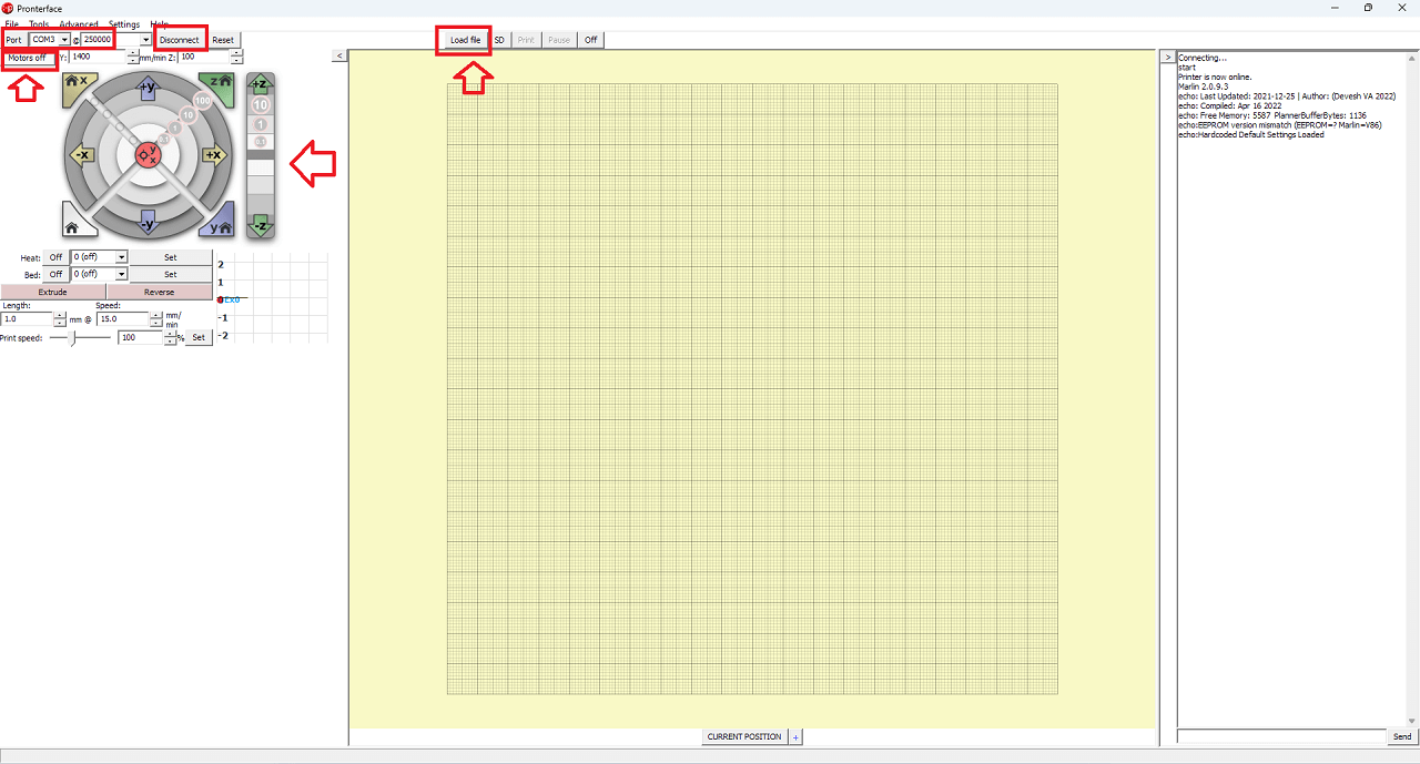 |
To use pronterface just connect the shield first to the PC and then run pronterface on the machine. You will see the com ports define on the top left with the baud rate. Click on the 'Connect' button, you will notice that the shield will provide some information about itself through the firmware and says its connected.
Control the motors and check if the hardware is working with the software by clicking the X, Y and Z axis controls if necessary. Through trial and error now we can determine and set the direction of the machine (+X, -X, +Y and -Y) as seen in the video below.
For calibration and feed rate, we used the prusa calculator. to set our values in the firmware and have and made a bit of trial and error cases also. We installed limit switches and set-up the machine home position by activating the limit switches as seen in the video below.
Reference tutorial for calibration:
Reference tutorial for homing and offset:
Some Important G and M codes:
Machine codes like G code and M codes are used to control a cnc machine through a CLI. In pronterface we could individually send G code and M codes to setup the homming and perform other functionality.
1. G28 - Homing position
2. G90 - Absolute positioning
3. M1 - Sleep
4. M2 - Program End
5. M12 - Enable stepper motors
6. M30 - Program Stop
7. M84 - Motors Off
8. M114 - Get Current Values
9. M428 - Set an arbitary Value
10. M500 - Stores the set value
How to Generate G-code using Slic3r:
We are assuming that the bed size is set to 80x80 mm.
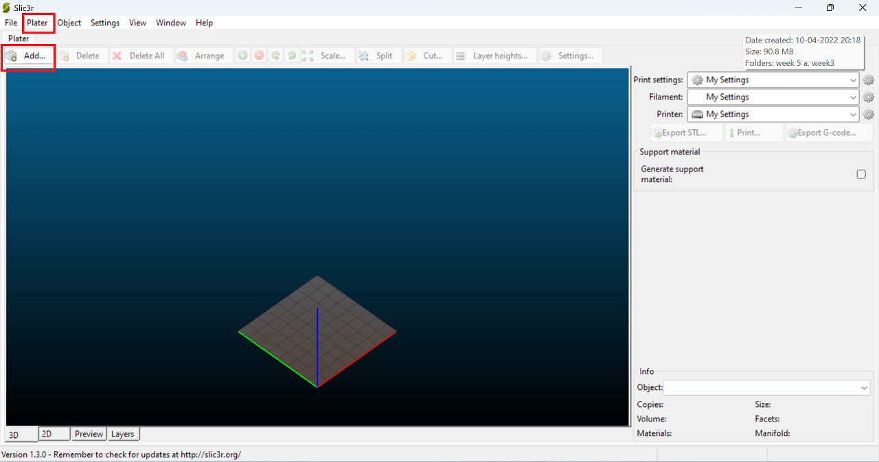
- Open slic3r application as shown in the image below. Click Add in plater tab and import an .stl file
 |
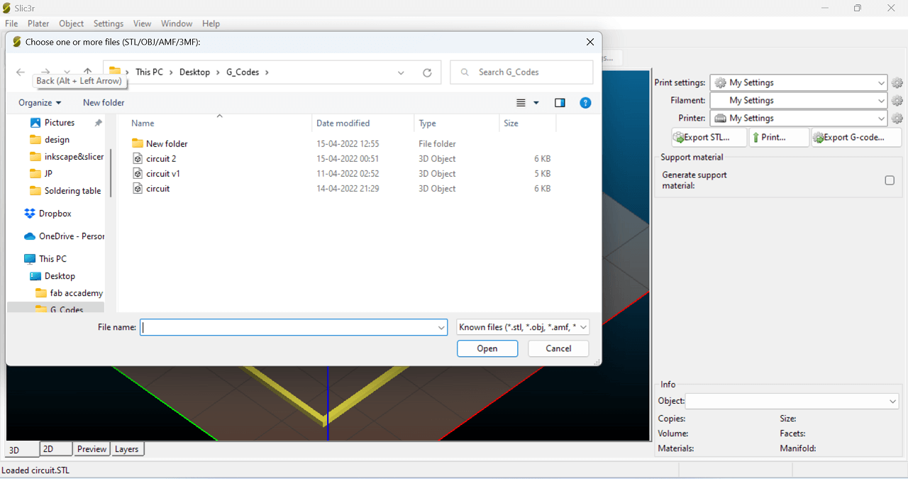 |
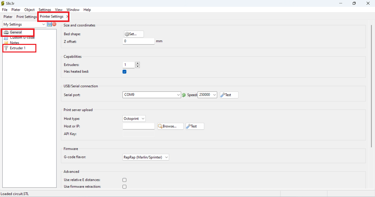
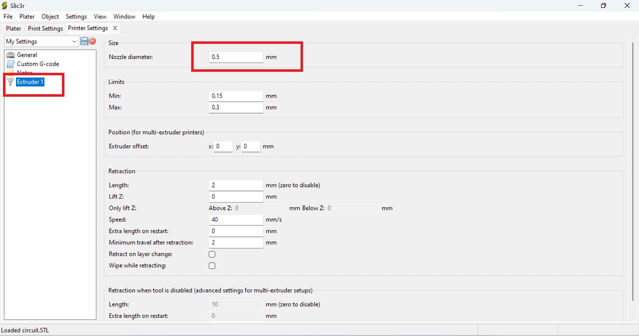
The file appear on the 3D plater tab. After which we have to check some parameters. Click Printer settings tab, general and set bed size, click Extruder1 and change the nozzle diameter if needed.
 |
 |
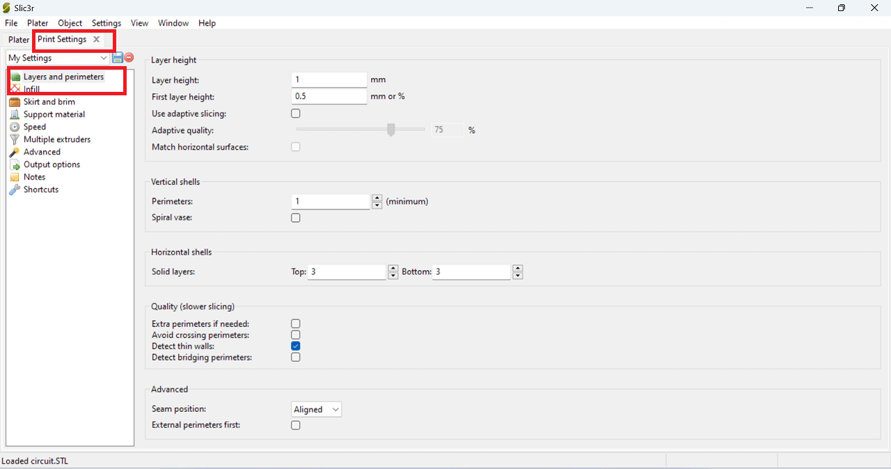
Click Print setting and set the Layer height and First layer height as shown in the image below.
 |
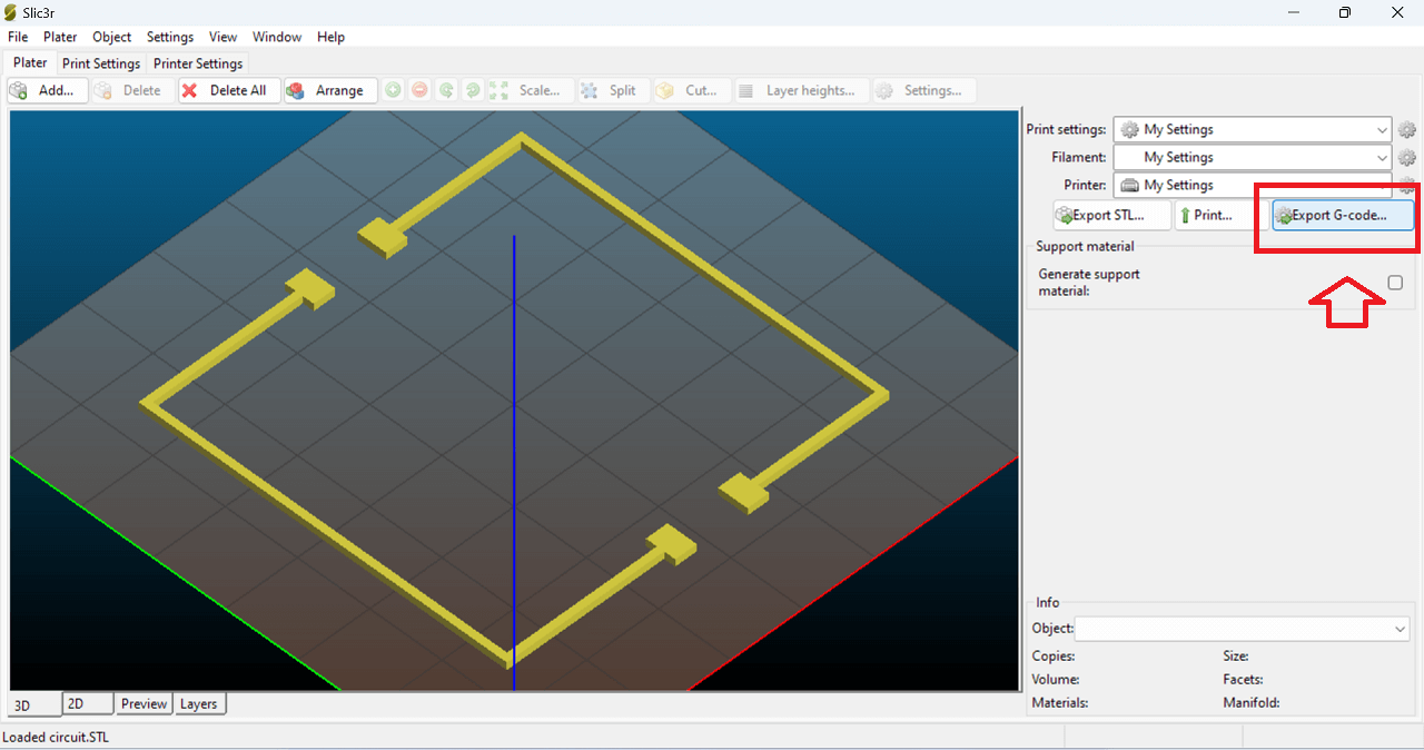
Then, go to the plater tab and click "Export to Gcode", give the desired name location of the file.
 |
Important points (learning) that we listed for electronics part:
- Know the board that you are using in this case it is an Arduino mega and a ramps shield. Note:- Do check the support list on Marlins site about the hardware that you are going to choose.
- Compile and Upload the Code on to Arduino mega.
- After uploading download Pronterface. (Pronterface is a software that provides an interface for controlling the motors of our machine.)
- After installing pronterface open and click connect to connect the Mega cum Ramps to pronterface to control the motors.
- Check the movement of the motor. Check the stepping. Mount the motor to the gantry assembly and check the XY movements. If the gantry isn't assembled properly there will be a jerking motion on XY movement else everything will go smoothly.
- Check the extruder motions. After this the next step is to set the homing positions of the machines using limit switches/end-stops.
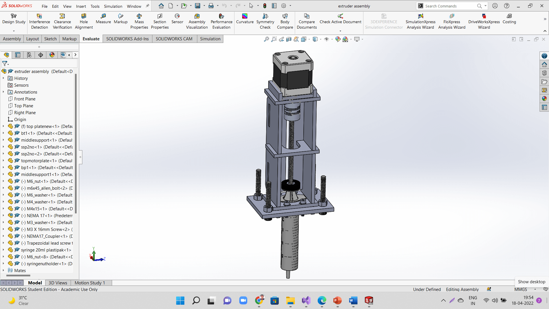
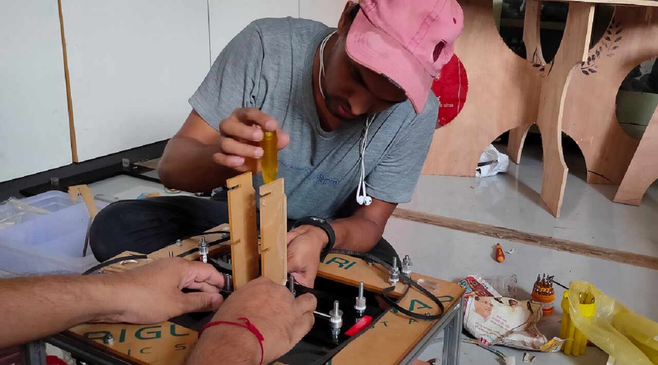
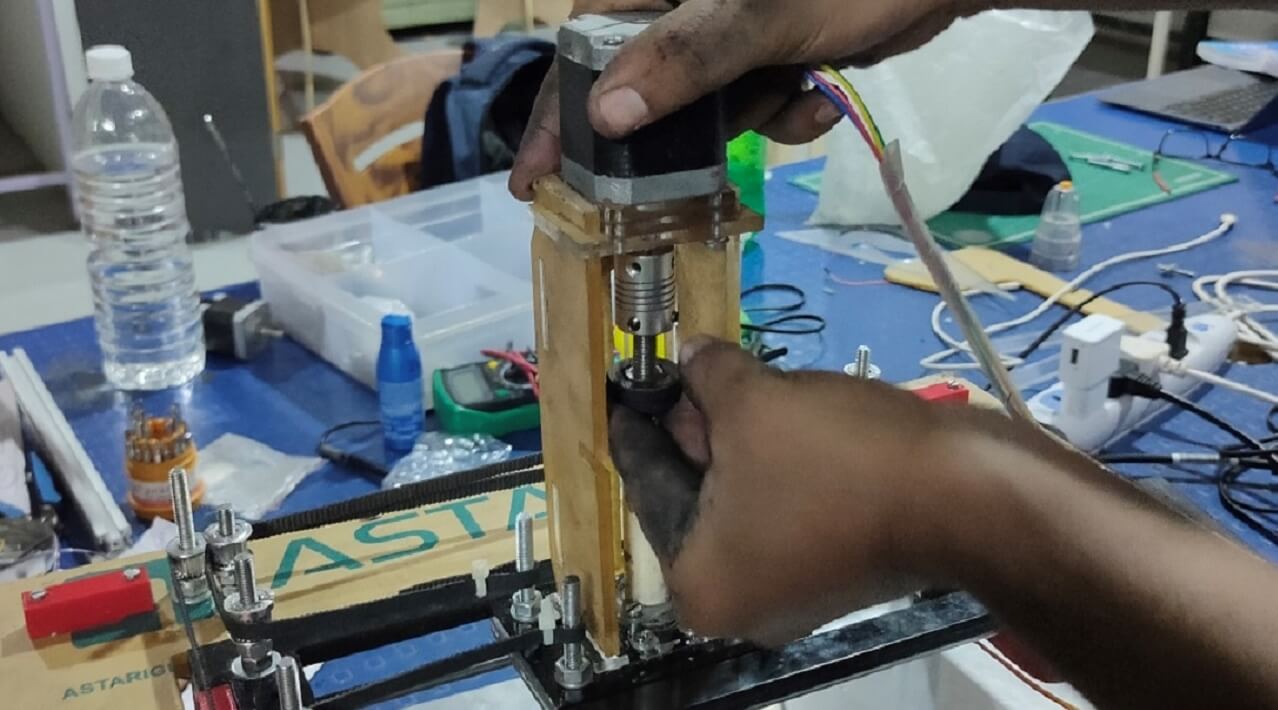
Extruder Design, assembly and Printing material preparation:
We laser cut parts for extruder assembly and also used some of the standard bought out parts like syringe to build it's assembly as shown below.
 |
 |
Video below shows simulation of extruder assembly.
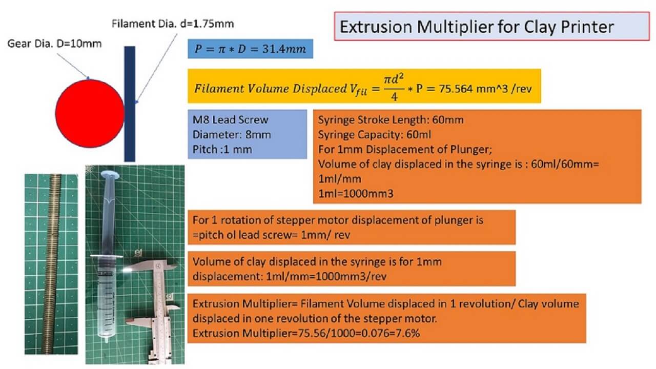
Following picture shows calculations we did to find out the extruder lead screw rotations and displacement to meet the best printing feedrate
 |
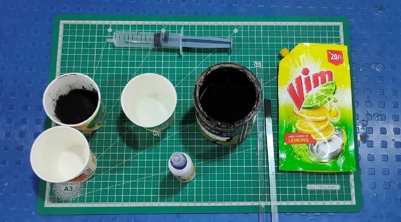
Following are the material that we used to prepare the conductive ink.
 |
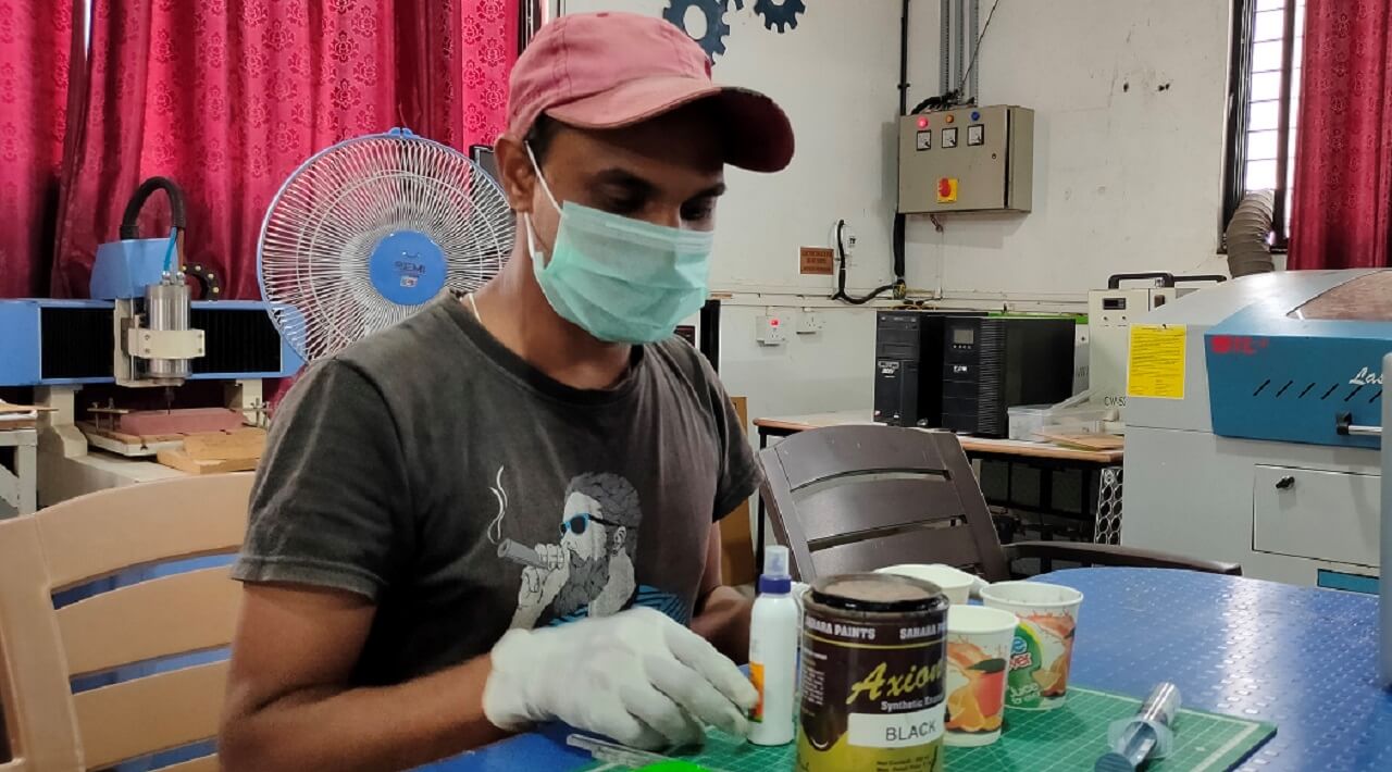 |
Video below shows the way we prepared conductive ink.
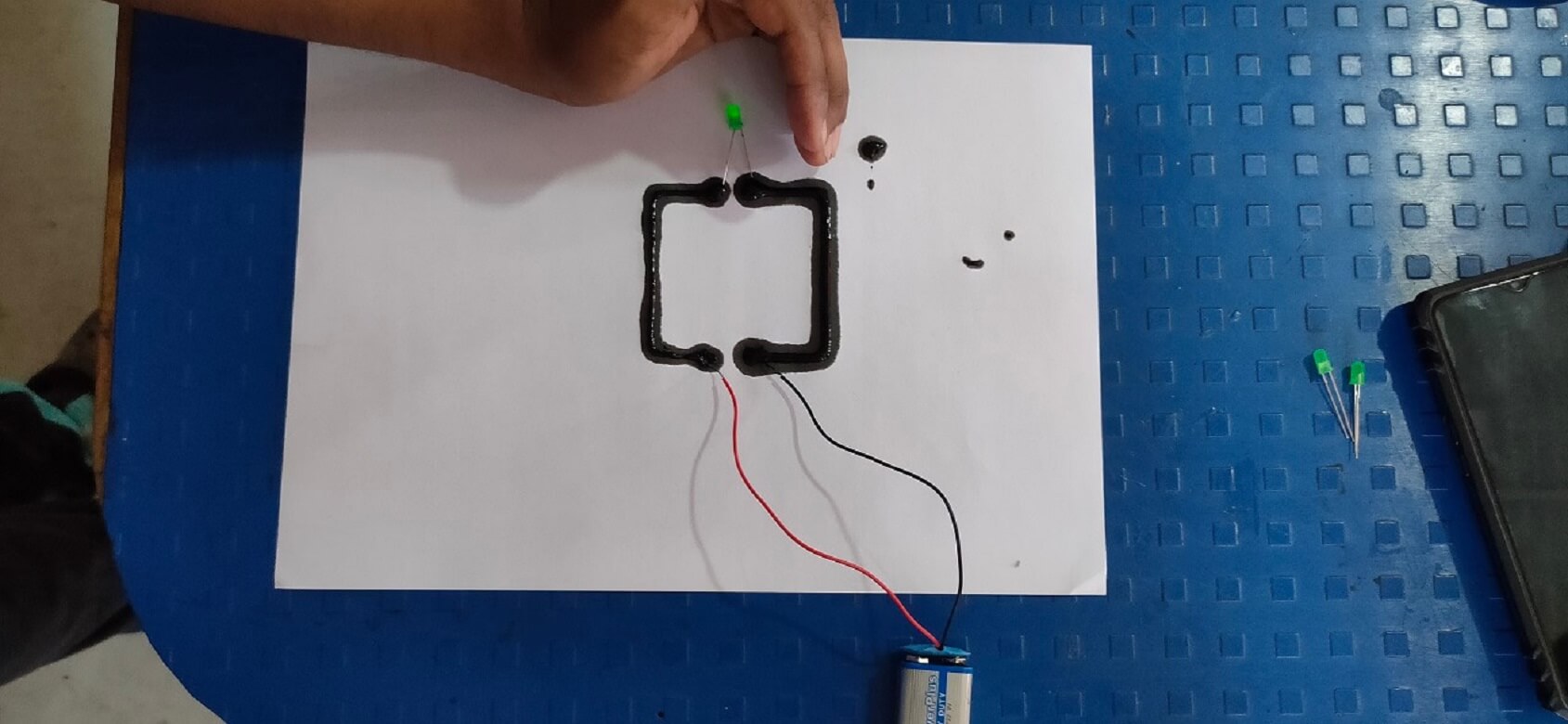
Conductivity test of the ink is shown below. The voltage across the ink drops to around 5 V enough to turn the LED on as shown in the pictures below.
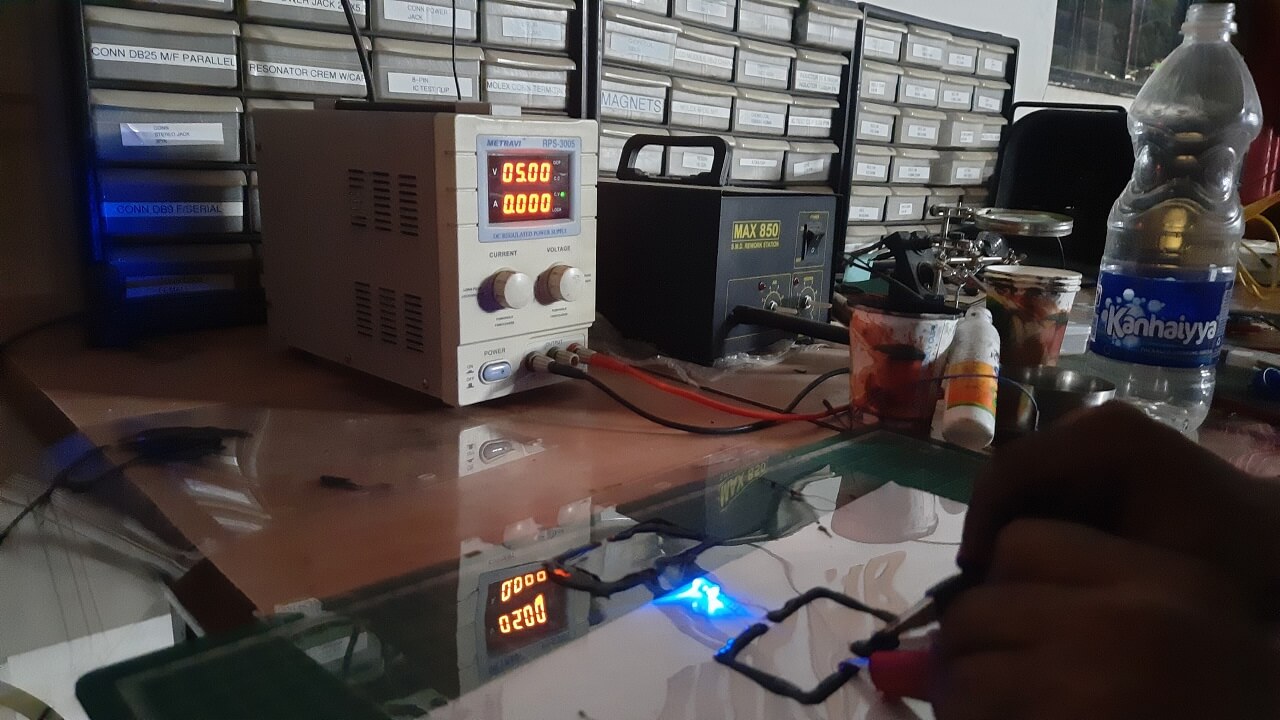 |
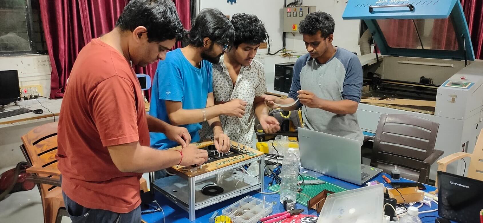
We did multiple trials on extruder to see if it is extruding the ink properly and as per the desired circuit diagram we have through g-code. Following is video of one such testing.
Test Runs:
Following is a video that we were waiting for all these two weeks :-)
We also did trials on the machine by preparing the conductive dough/clay as shown below. We will do trials using this dough in coming days.
 |
Final video link
Original Files for download:
Click here to download CAD files.
Click here to download our firmware files.