Group Assignment #2: Electronic Production
This week, we worked on Electronic Production group assignment. This assignment is about documenting what we learned in Electronics Production that includes PCB fabrication processes, PCB material, components, PCB assembly (including processes and tools). We have also documented how we used machining process for PCB, tools, what precautions need to be taken while operating the milling machine.
 |
 |
Objectives of this Group Assignment:
- Understand PCBs, their types, fabrication processes, material and tools
- Understand how to operate the PCB milling Machine
- Learn safety precautions while operating this Machine
- Characterize the design rules for your in-house PCB production process
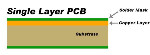
What is PCB: A printed circuit board (PCB) is a laminated sandwich structure of conductive and insulating layers. PCBs have two complementary functions. The first is to affix electronic components in designated locations on the outer layers by means of soldering. The second is to provide reliable electrical connections (and also reliable open circuits) between the component's terminals in a controlled manner often referred to as PCB design.
PCBs mechanically support electronic components using conductive pads in the shape designed to accept the component's terminals, and also electrically connect them using traces, planes and other features etched from one or more sheet layers of copper laminated onto and/or between sheet layers of a non-conductive substrate.[1] Components are generally soldered onto the PCB to both electrically connect and mechanically fasten them to it. Printed circuit boards are used in nearly all electronic products and in some electrical products, such as passive switch boxes.
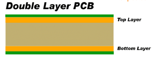
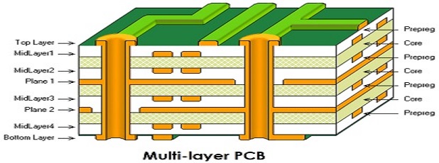
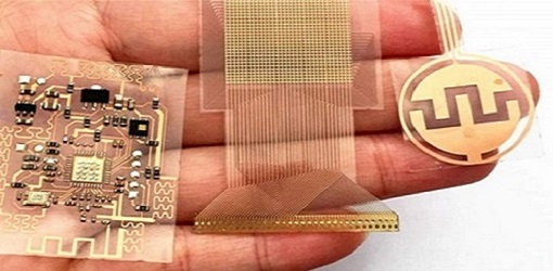
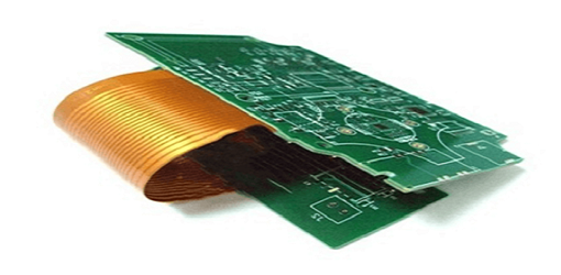
There are many types of PCBs like single layer PCB, Double layer PCB Multiple layer PCB, flexible PCB, rigid-flexible PCB, etc.
Types of PCBs
 |
 |
 |
 |
 |
PCB Fabrication (Process, Material, Machine and Tools)
In this section, we are documenting machining (end milling) as process for PCB fabrication and required PCB material, machines and tools.
Machining (Milling) for PCB Fabrication
Printed circuit board milling (also: isolation milling) is the process of removing areas of copper from a sheet of printed circuit board material to recreate the pads, signal traces and structures according to patterns from a digital circuit board plan known as a layout file. Similar to the more common and well known chemical PCB etch process, the PCB milling process is subtractive: material is removed to create the electrical isolation and ground planes required. However, unlike the chemical etch process, PCB milling is typically a non-chemical process and as such it can be completed in a typical office or lab environment without exposure to hazardous chemicals. High quality circuit boards can be produced using either process. In the case of PCB milling, the quality of a circuit board is chiefly determined by the system's true, or weighted, milling accuracy and control as well as the condition (sharpness, temper) of the milling bits and their respective feed/rotational speeds. By contrast, in the chemical etch process, the quality of a circuit board depends on the accuracy and/or quality of the mask used to protect the copper from the chemicals and the state of the etching chemicals. Click here to read more.
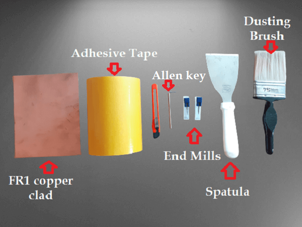
Material, Machine and Tools used in PCB Machining (Milling)
Material:
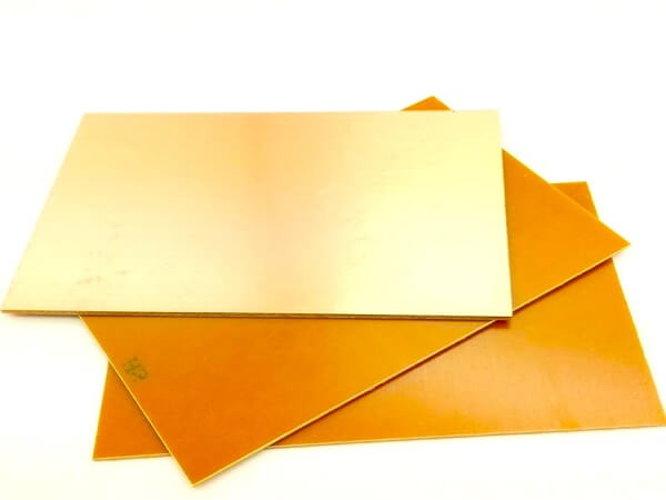
- FR1-Phenolic paper is a material often used to make printed circuit board substrates (the flat board to which the components and traces are attached). It is a very tough board made of wood fibre and phenolic polymers. It is most commonly brown in colour, and is a fibre reinforced plastic. These PCB materials are known as FR-1 and FR-2.
- Epoxy Film Electrical Tape with Thermosetting Acrylic Adhesive
- Electronic componets
Machine:
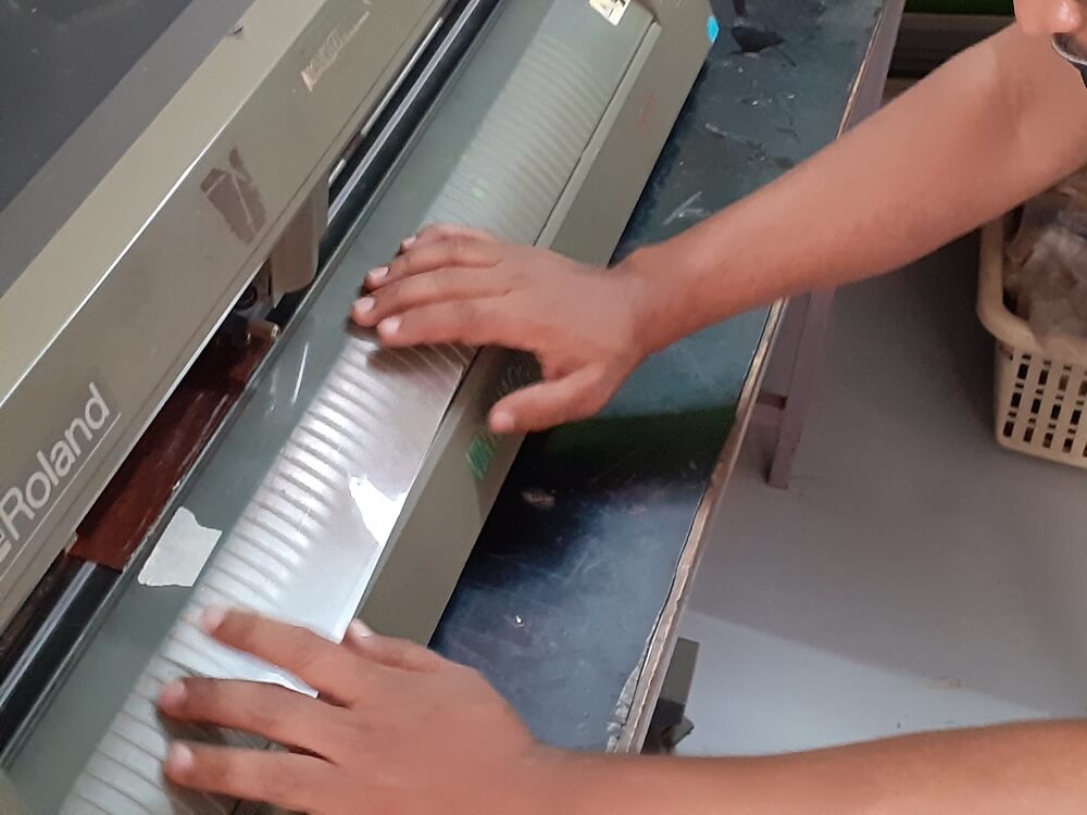
- The mechanics behind a PCB milling machine are fairly straightforward and have their roots in CNC milling technology. A PCB milling system is similar to a miniature and highly accurate NC milling table. For machine control, positioning information and machine control commands are sent from the controlling software via a serial port or parallel port connection to the milling machine's on-board controller. The controller is then responsible for driving and monitoring the various positioning components which move the milling head and gantry and control the spindle speed.
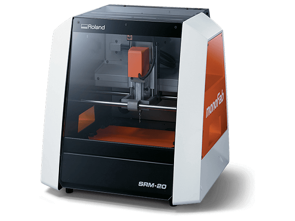
- e.g. Roland SRM-20 is a precision three-axis machining, including PCBs down to 0.25 mm feature size, and machineable wax to make tooling for molding and casting
Tools:
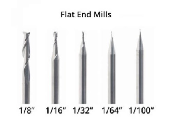
- PCBs can be machined with conventional endmills. Flat end mills have many advantages. Their straight profiles and consistent diameters ensure that milled traces are of a consistent width, even if the FR-1 PCB blank used is not perfectly flat. Flat end mills are also great at clearing large areas of material, and large flat end mills can remove material very quickly.
 |
 |
 |
 |
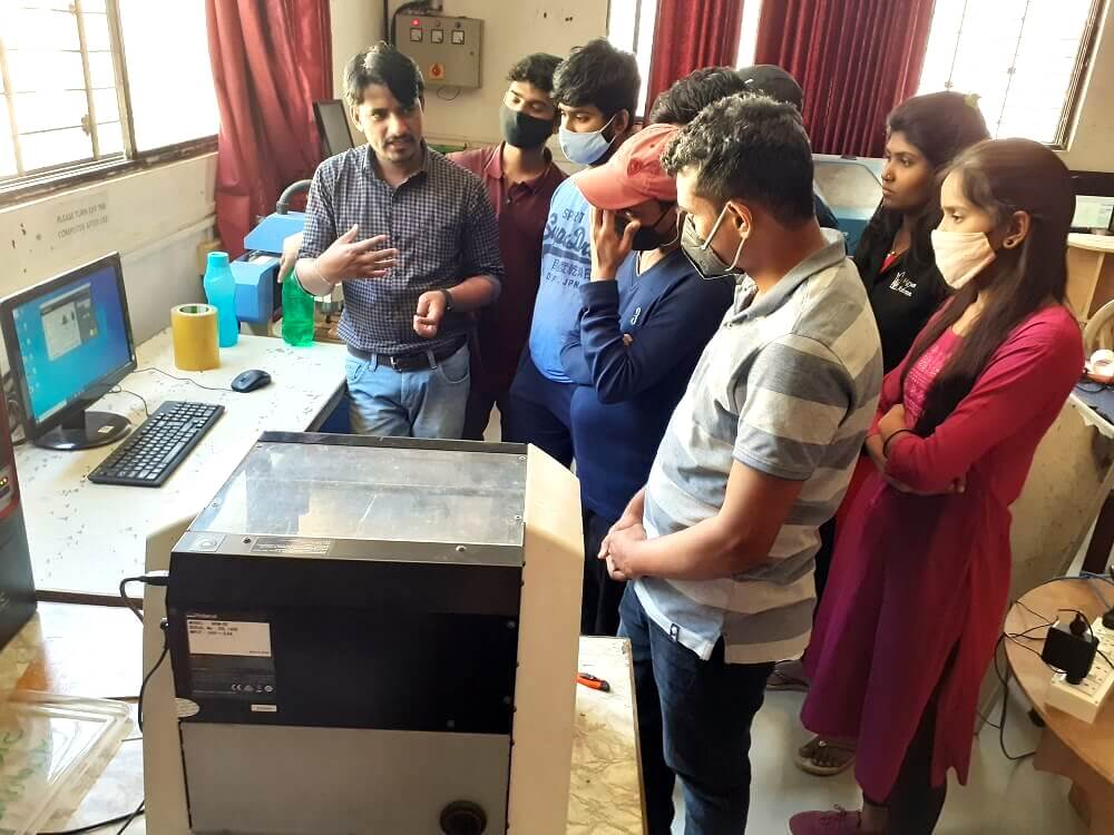
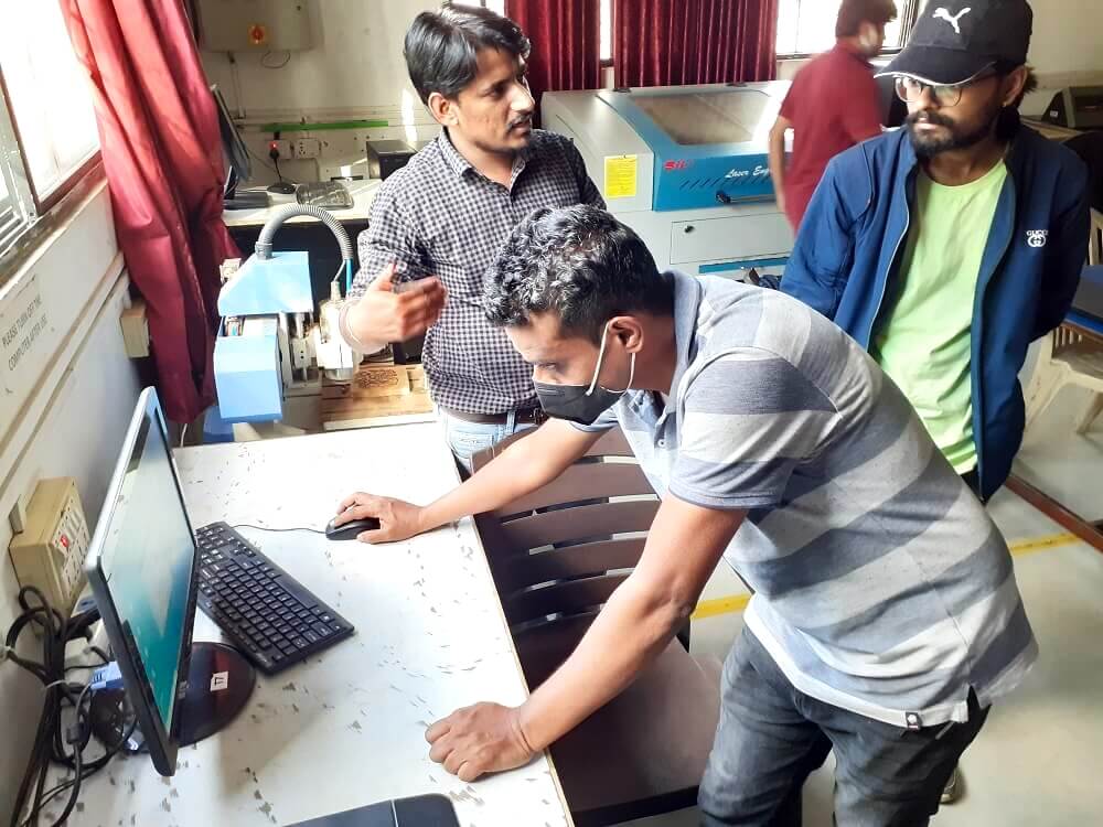
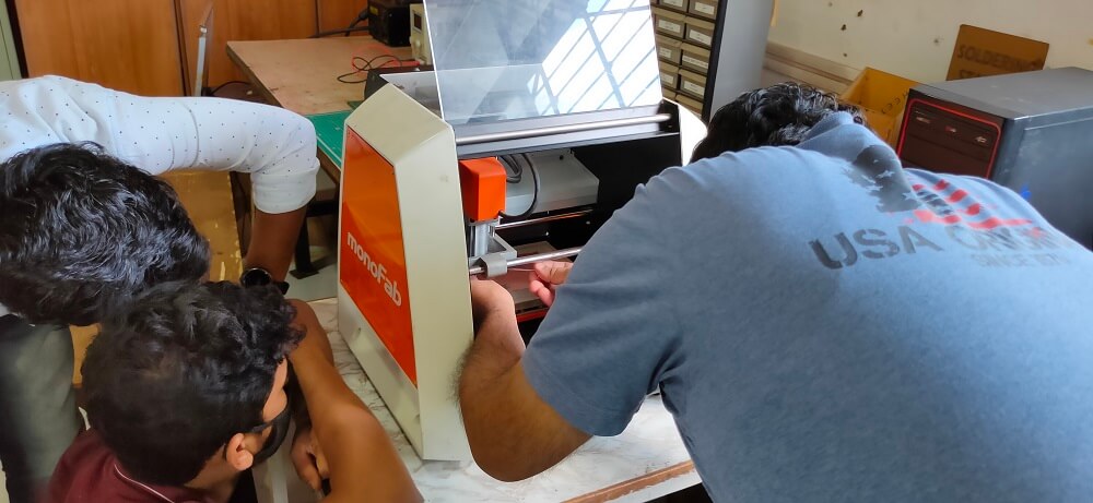
Operate PCB milling machine
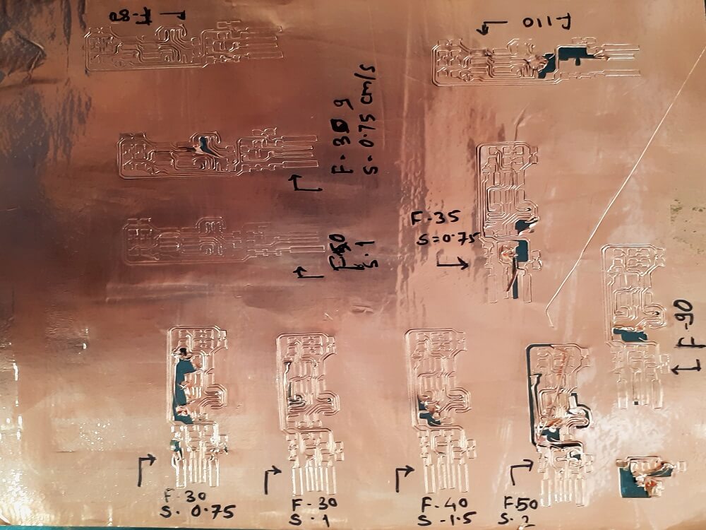
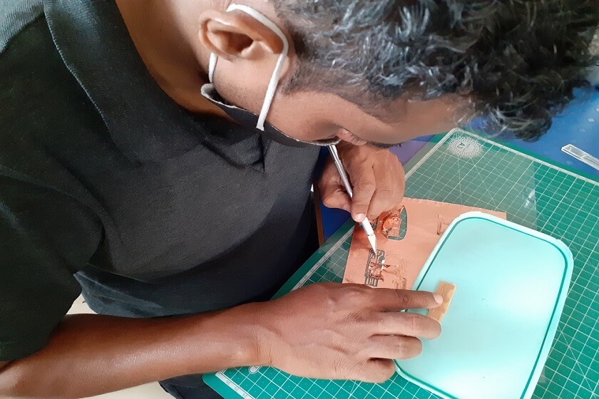
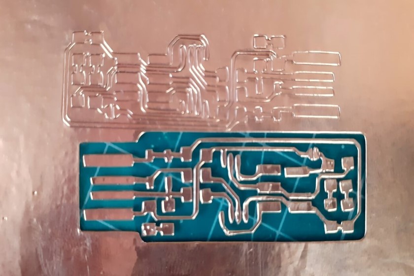
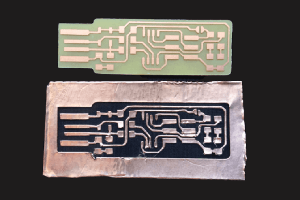
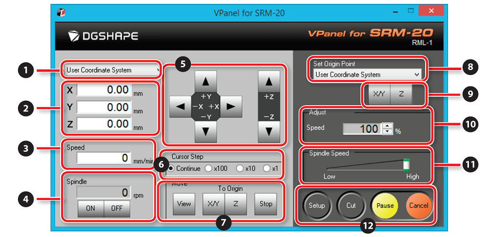
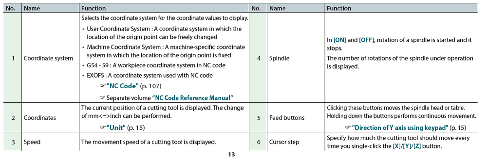
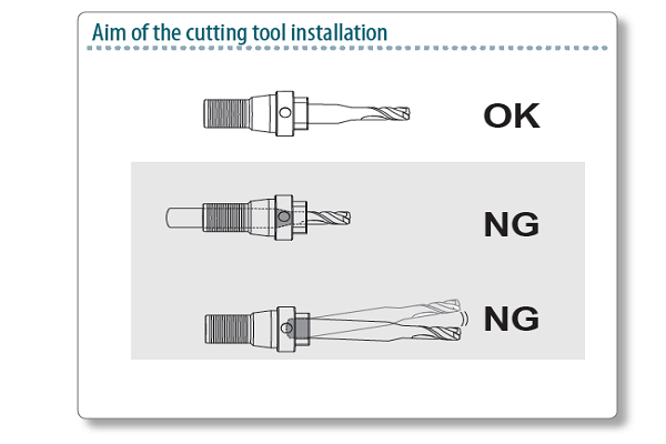
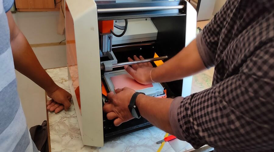
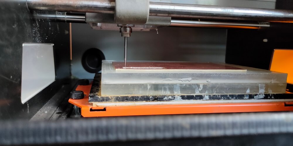
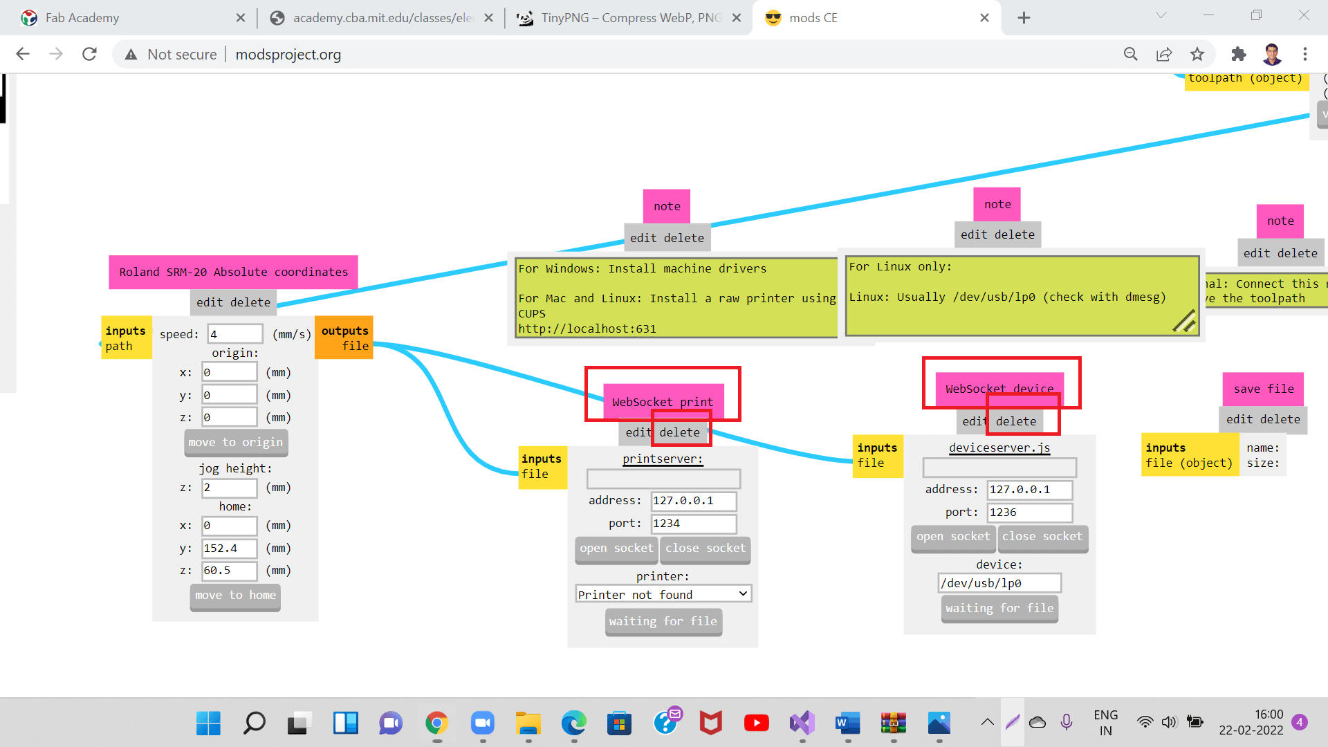
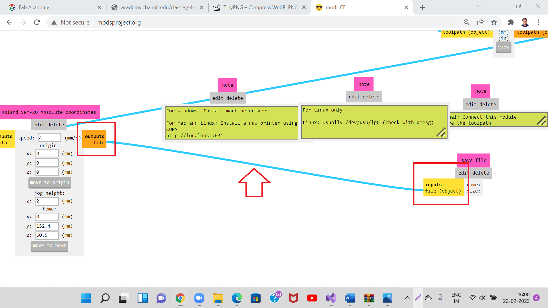
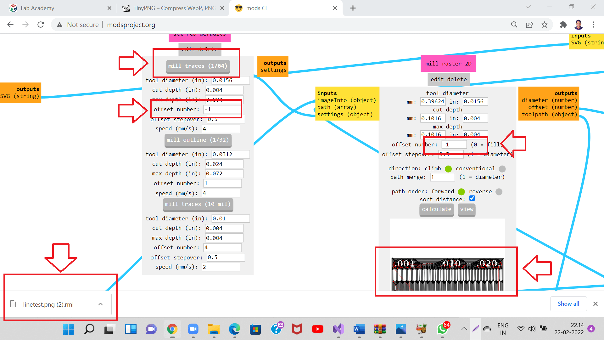
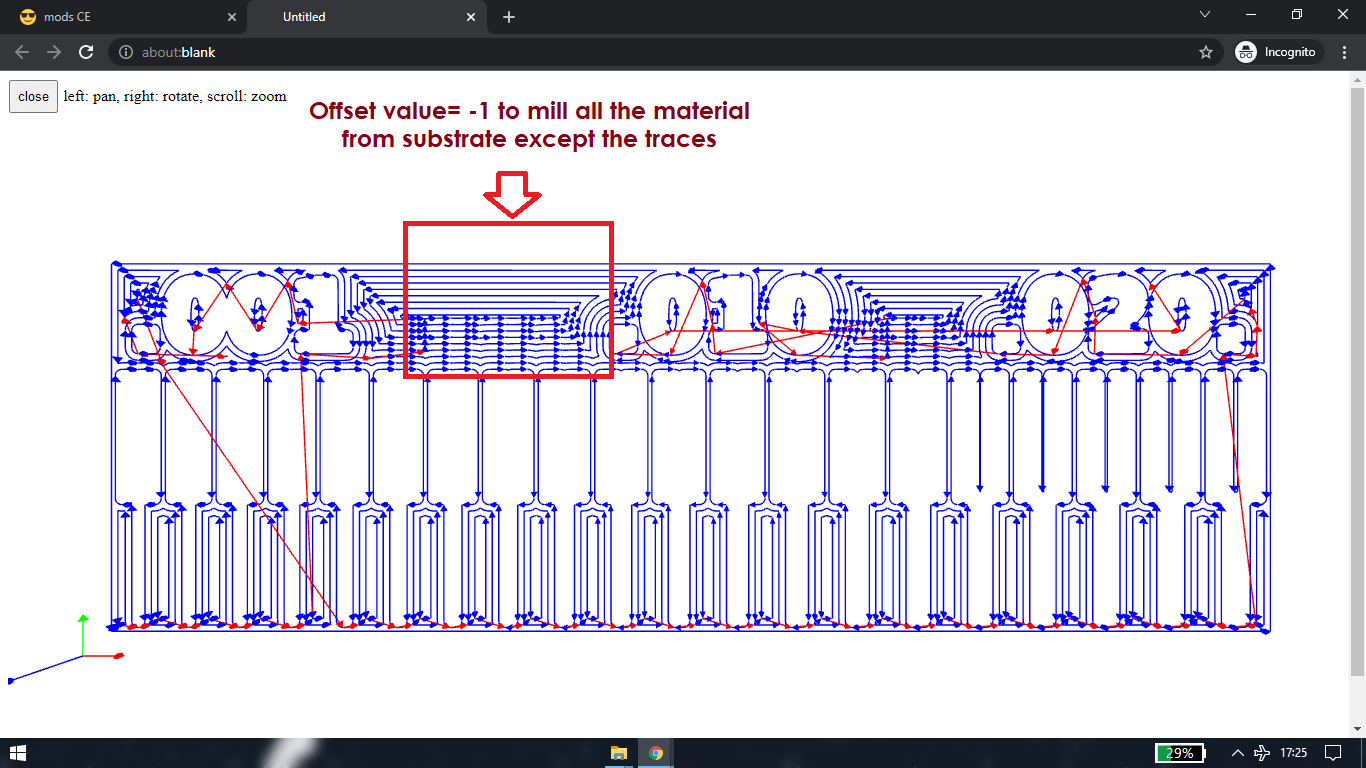
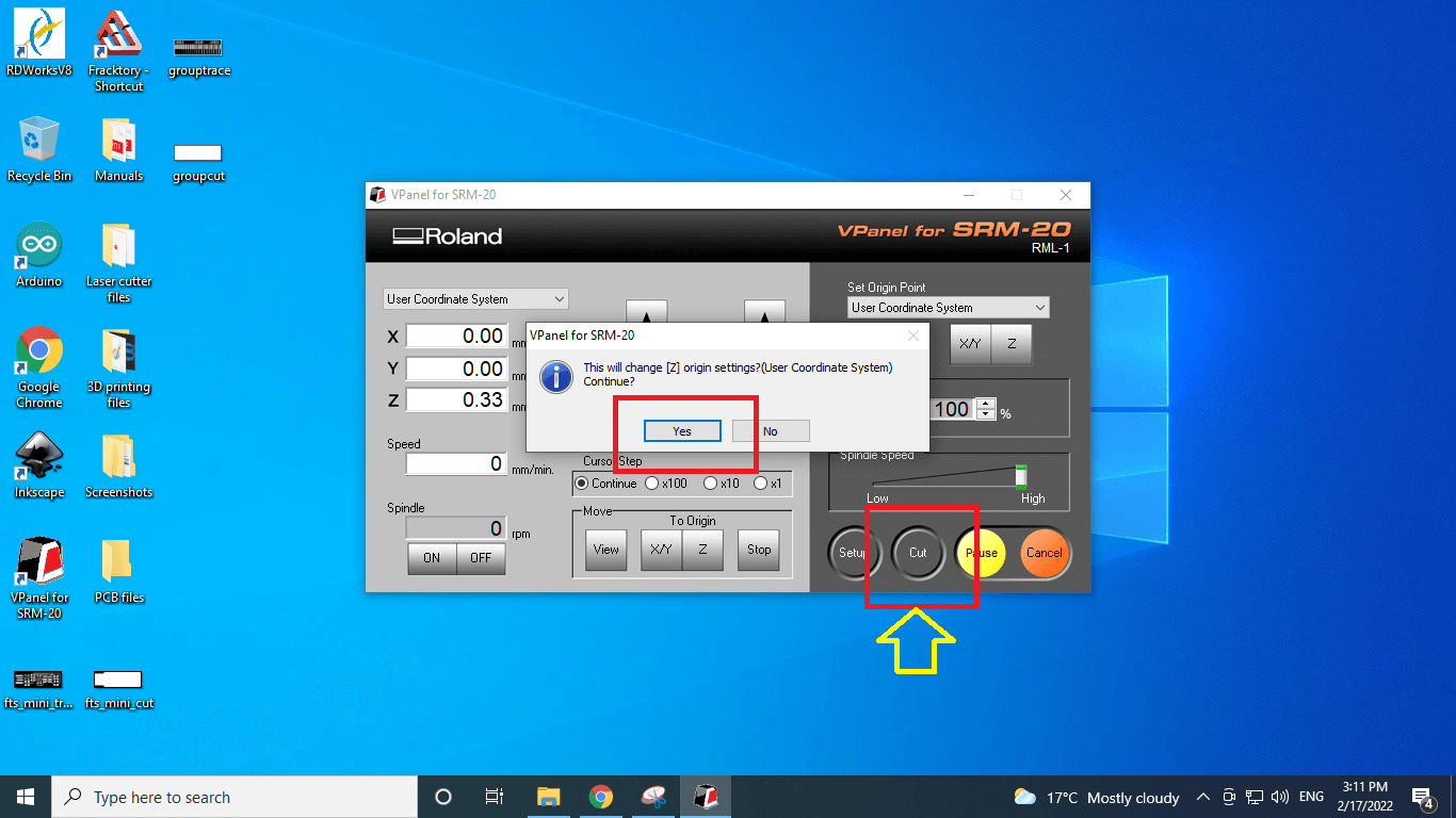
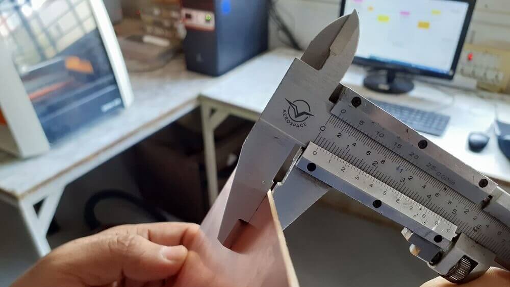
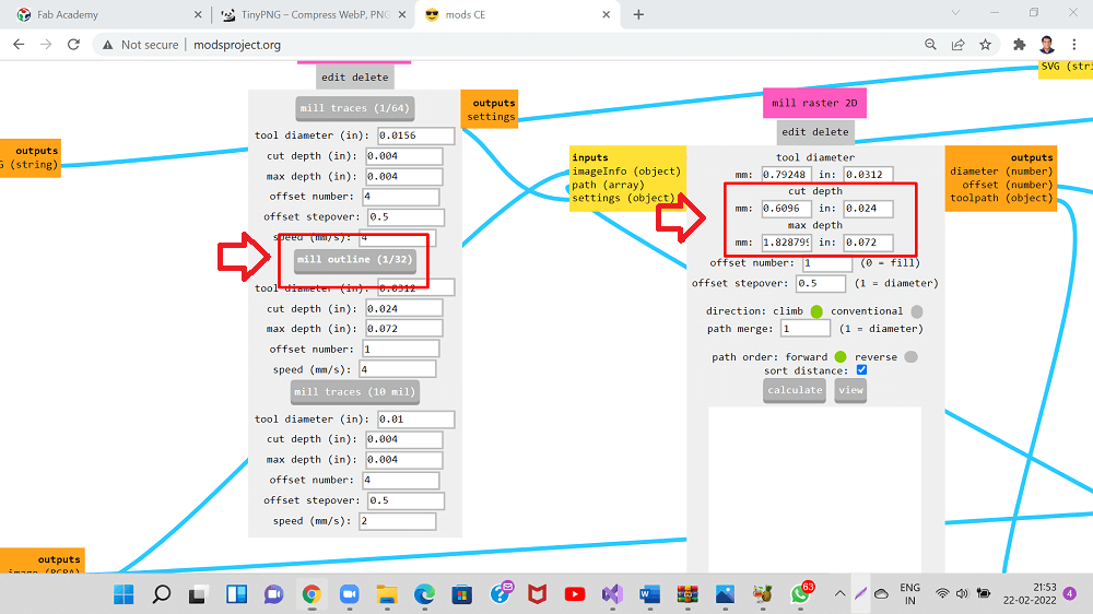
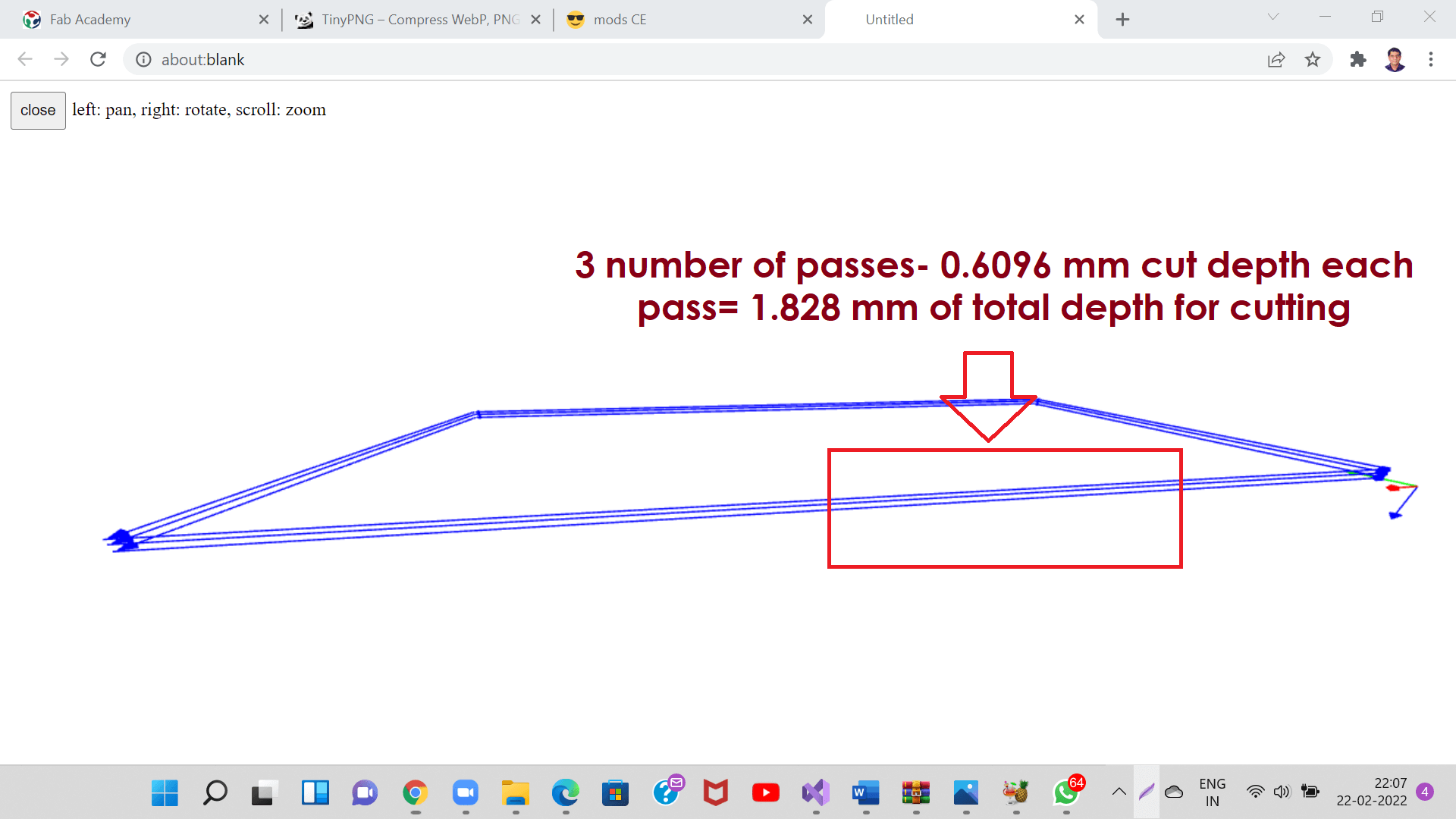
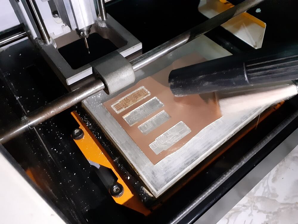
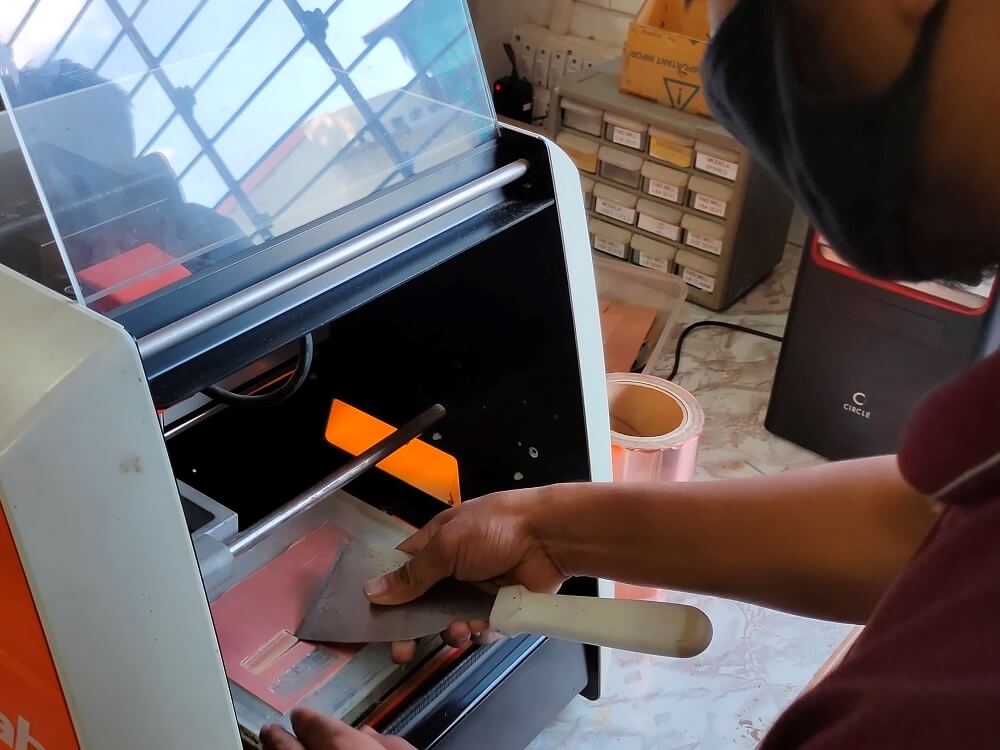
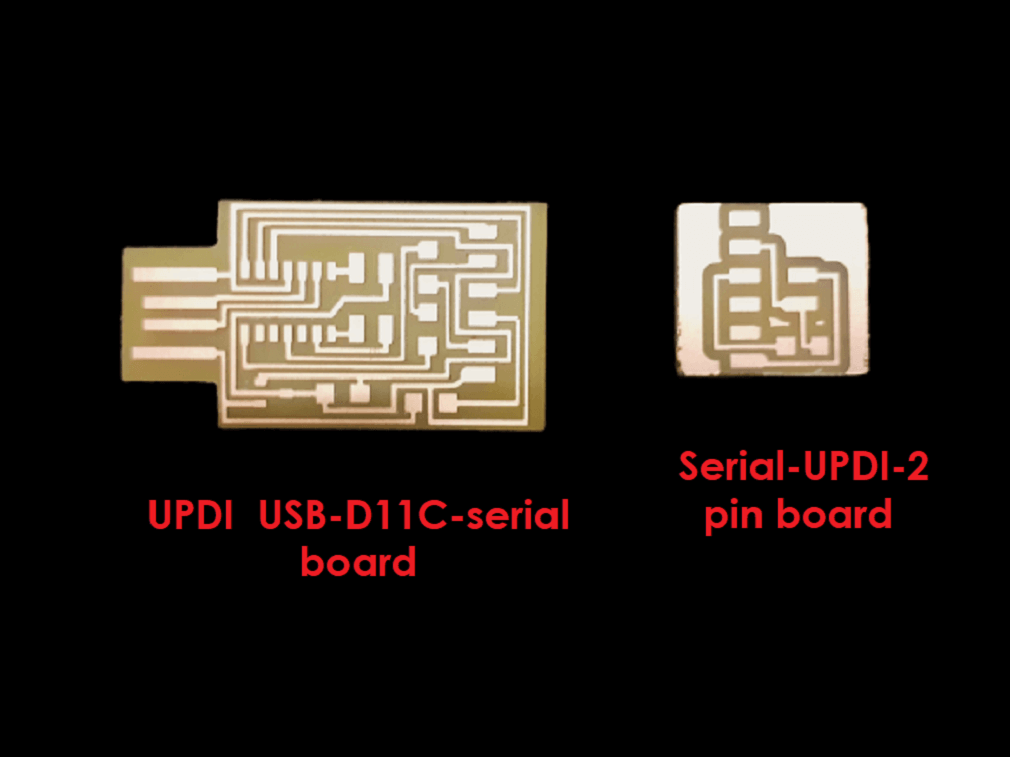
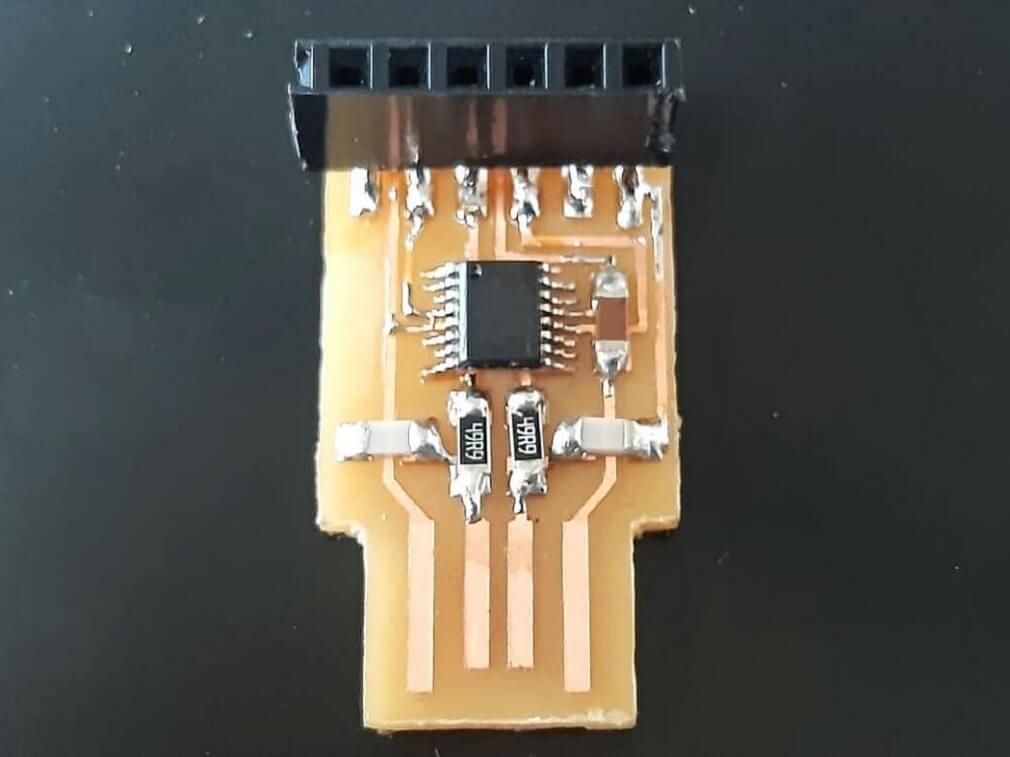
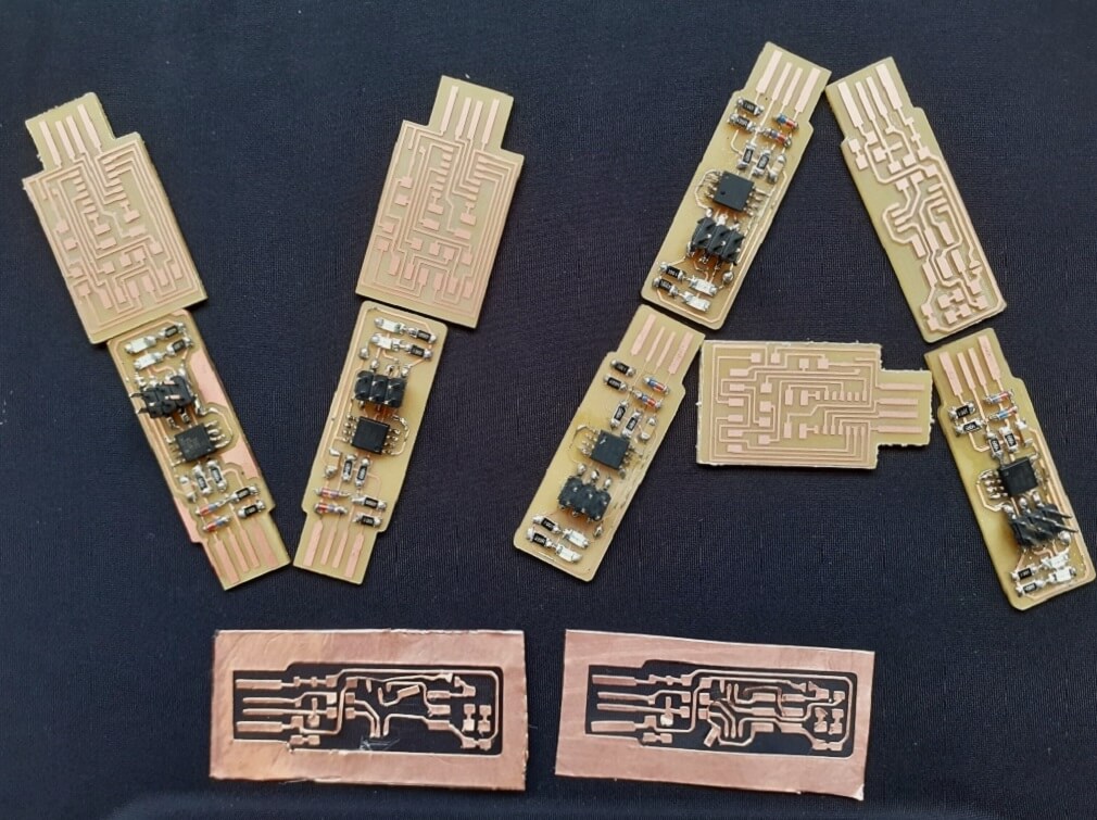
We understood the basics of the Roland SRM-20 desktop milling machine before we started operating it. Following are the details of the machine. VPanel controller of SRM20: Following are the menu on Vpanel controller and functions of each one of them. Following are the steps we followed to operate the milling machine properly. All of us operated it and ran it dry 3-4 times without using the tool just to practise. For better quality of the PCB milling and improved tool life, it is very much important to follow specific recommended steps in setting-up the end mills. Following are the steps that we follwed for the same. The right most picture in the first row below shows the correct alignment of the tool with respect to the spindle axis. Similar to setting up the cutting tool, it is important to set-up the substrate on the table correctly. Following are the steps that we followed: Before you start cutting, you must set the origin point. When you cut with this machine, you need to set the X, Y, and Z origins. - Click [X][Y] cursor button, move right above the origin point. - Click [X/Y][Z] of set origin point. First, We downloaded the trace and cut layout PNG files for FabISP programmer. - Then, we opened mods project through browser. - Clicked 'WebSocket Print delete' and ''WebSocket device delete' buttons. We then added 'Save file' - Next, we clicked 'mill trace (1/64)' and changed 'offset number=-1'. Then 'offset number'= -1 got automatically reflected under 'mill raster 2D'. This -1 offset was given to remove all the material from the substrate except traces and paddings. Cutting speed for tracing was 4 mm/s. - Lastly, after the XYZ coordinates on machine are set to Zero as mentioned in earlier steps, we browsed the toolpath file in VPanel controller through cut button. Below is a video we captured as the trace milling process started. For cutting the board, once tracing was done, we moved the X and Y axis to its origin point, by clicking on the 'XY' button under 'to origin'. Once the X and Y axis are positioned, we inserted the 1/32 endmill into the collet the same way we did it with 1/64 endmill. Since the measured thickness of the substrate was 1.82 mm, the maximum depth of cut was set to be at 1.823 mm as seen in the pictures below, which was achieved in 3 passes, one pass was of 0.6096 mm each. Cutting speed was 4 mm/s. Rest of the procedure on Vpanel was same to cut the substrate using cut PNG file. Once the jobs are done, we vacuum cleaned the table top and machine to remove the waste safely. We took out our board using spatula. Finally, following are the pictures of our final board we cut to characterize the design rules for our in-house PCB production process. 1. The gap between two traces has to be more than the tool diameter. In our case, the tool diameter was 1/64 inch, i.e. 0.0156 inch, the tool did not create traces, where the gap between two traces was less than 0.0156 inch. The CAM software itself does not create the tool path, where the gap between two traces is less than the tool diameter. We machined three more programmer boards namely UPDI- USB D11C-serial, serial UPDI-2 pin, FTDIUSB-FT230X-UPDI and JTAG boards. We assembled and tested FTDI and JTAG boards. We made a flexible PCB using 3M Copper Foil Tape pasted on PVC sheet. We did multiple trials with different settings of cutting force and speed. Initially, we started with a force of 30gf and speed of 0.75 cm/s. However, it could not cut the foil properly. It damaged the traces. Then we gradually increased cutting force to 40 gf, 50gf, 80 gf, 90gf, 110 gf and finally 120 gf. We also varied speed from 0.75 cm/s to 2 cm/s. It could not improve much until a cutting force of 90 gf. As we went on increasing cutting force, it was able to trace better than the previous settings and we arrived at an optimum setting, where the machine could cut the traces properly. They are cutting force=120 gf and speed of 2 cm/s. We could see from behind the PVC sheet that all the traces are cut properly. We enjoyed weeding this PCB using tools. Finally this is how our first ever flexible PCB is cut on vinyl cutter.
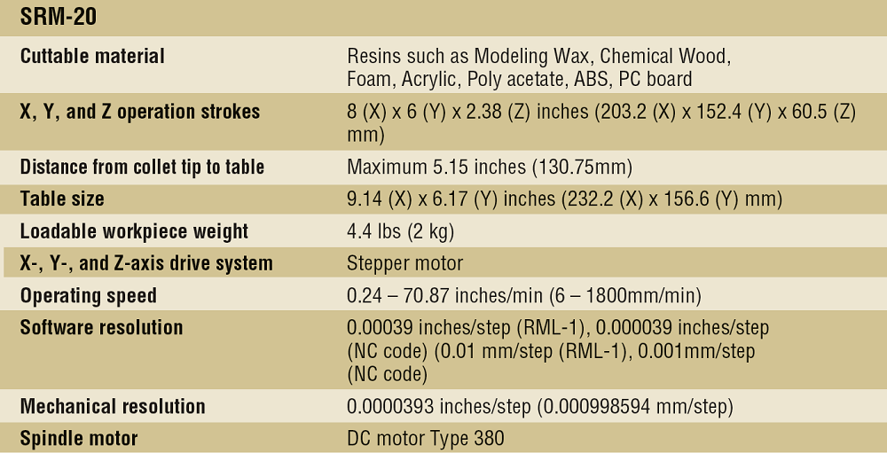
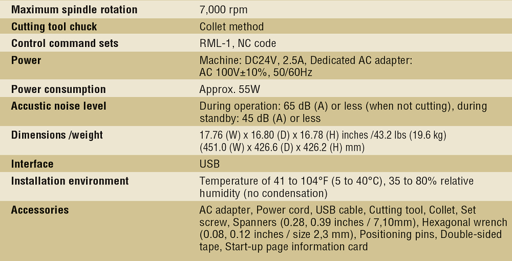
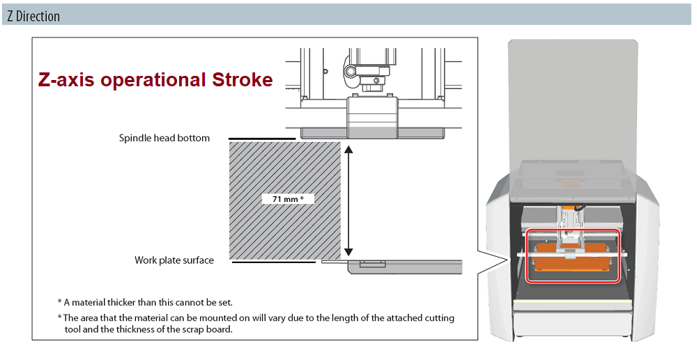
Roland SRM20 Milling machine is a precision three-axis machining, including PCBs down to 0.25 mm feature size, and machineable wax to make tooling for molding and casting. A wide range of materials, including modeling wax, chemical wood, foam, acrylic, poly acetate, ABS and PC board can be precision milled using the SRM-20 small milling machine, allowing you to create realistic 3D prototypes that are virtually identical to production parts. Engineered for optimum efficiency and productivity, the SRM-20 is a next-generation desktop mill that boasts a micro-step motor drive system for clean and precise contours and a phenomenal feed rate that is two times faster than previous generations.
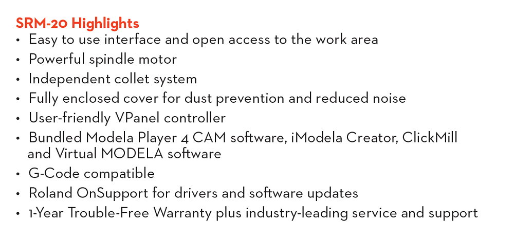
The SRM-20 has touch-button VPanel controller to regulate feed rate, spindle speed and milling on a complete X, Y, Z axes, and a new independent collet system that allows for faster setting of the Z-axis base point and quick tool changes. Click to know more
SRM-20 Highlights
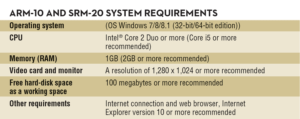
Specifications and system requirements of SRM-20
How to operate the PCB milling machine:
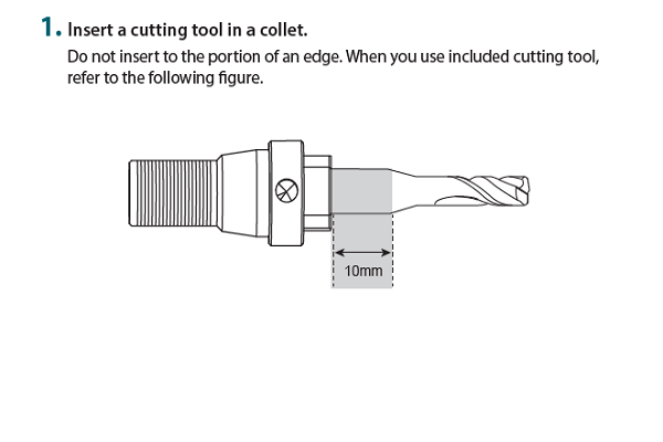
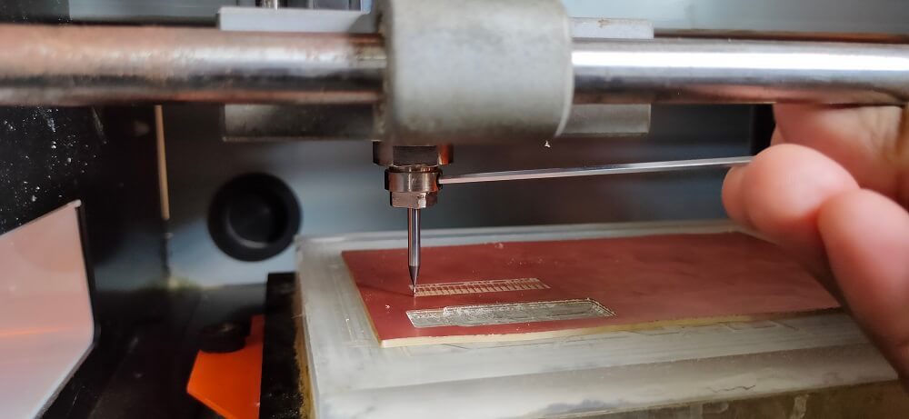
1. Setting up the cutting tool (End mill):
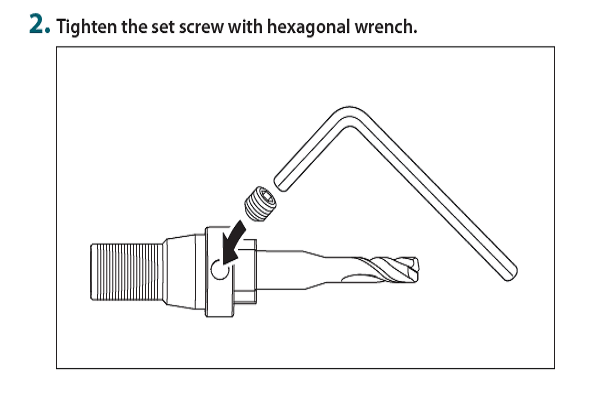
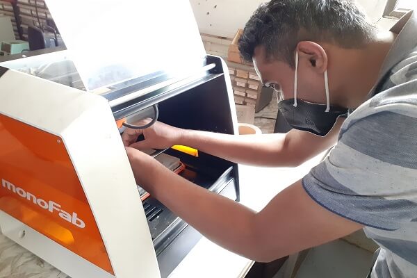
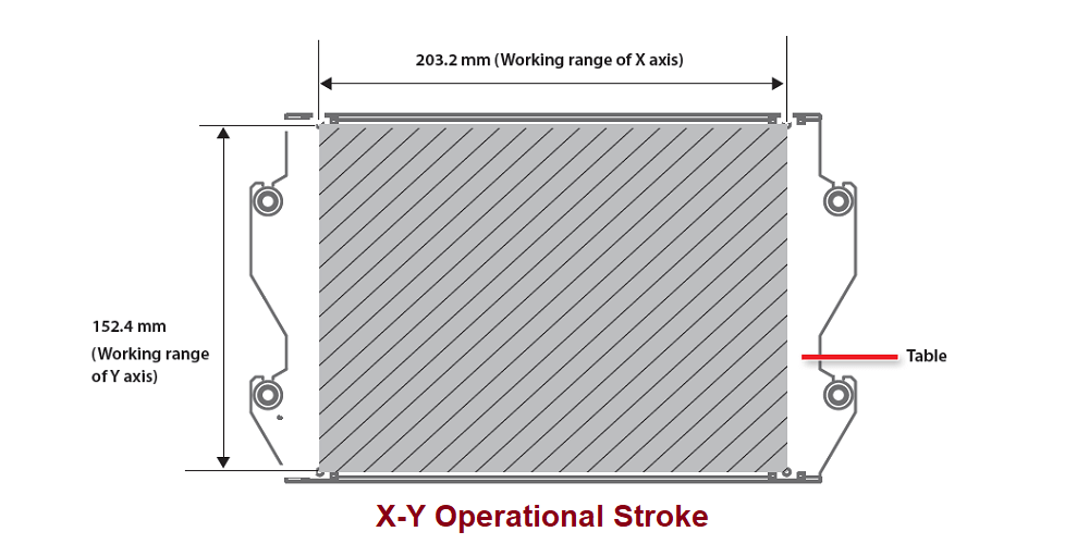
2. Setting up the substrate on the machine table:
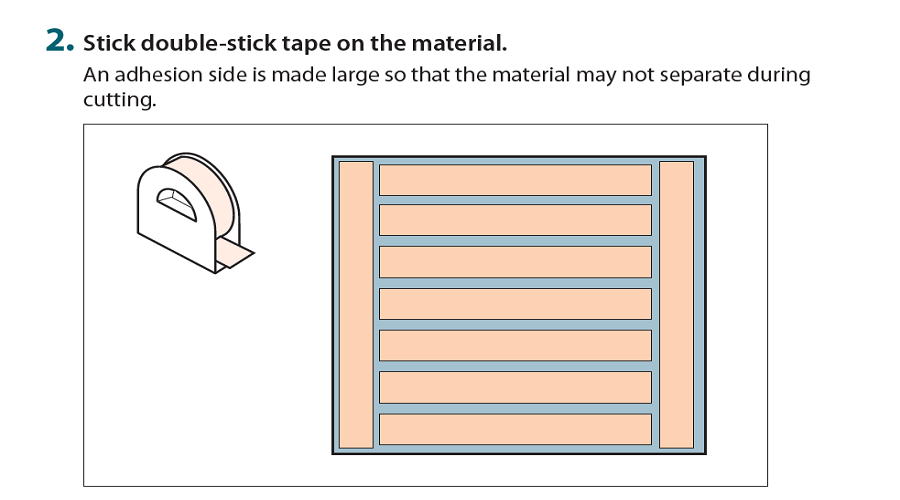
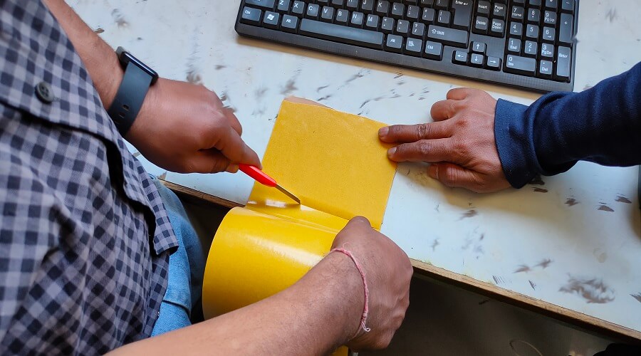
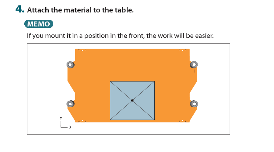
1. Put the double sided adhesive tape at the backside of the substrate surface. Make sure, it does not get bubbles and adhesive is applied uniformly. Cut the excess adhesive with cutter.
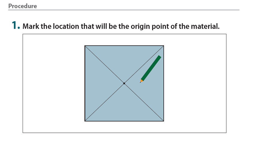
2. Place the substrate on the table We use the VPanel controller to move the machine table and bring it forward to be able to place the substrate properly in view mode. Set-up the substrate uniformly across the table in such a way that it has uniform level on the entire plane. Apply gentle pressure and check with spirit level. Then mark the Zero position on XY axis and mark it on the substrate with marker if possible to use the substrate properly without much of a wastage.
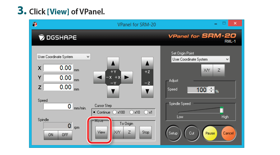
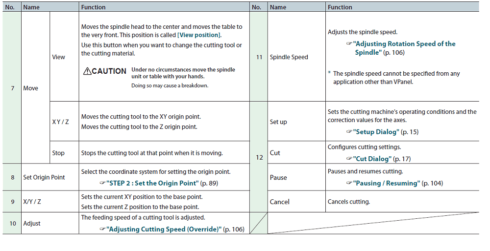
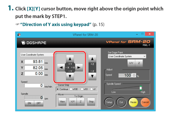
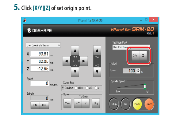
3. Prepare to set-up the origin point:
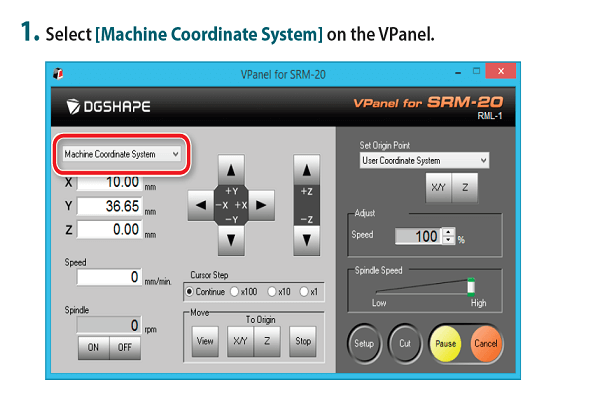
- First, Select [Machine Coordinate System] on the VPanel.
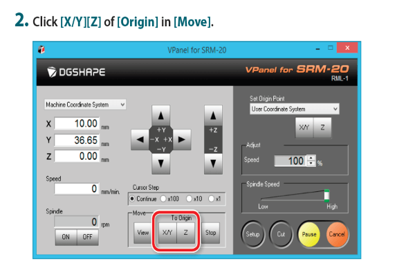
- Click [X/Y][Z] of [Origin] in [Move].
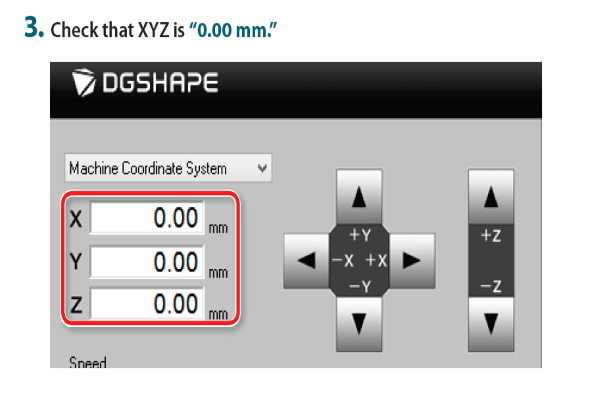
- Check that XYZ is 0.00 mm.
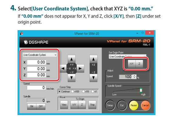
- Select[User Coordinate System], check that XYZ is 0.00 mm. If 0.00 mm does not appear for X, Y and Z, click [X/Y], then [Z] under set origin point.
4. Set-up the origin point:
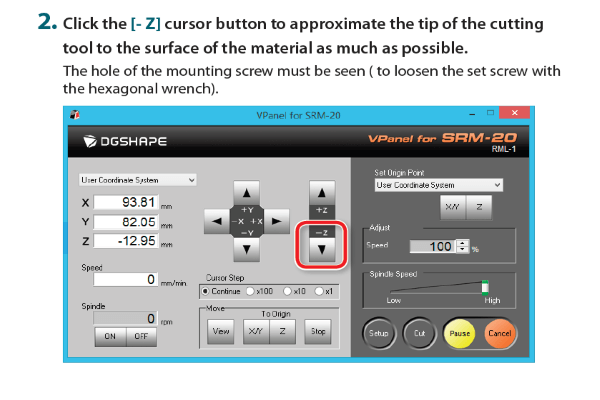
- Click the [- Z] cursor button to approximate the tip of the cutting surface of the material as much as possible. The hole of the mounting screw must be seen ( to loosen the set screw with the hexagonal wrench).
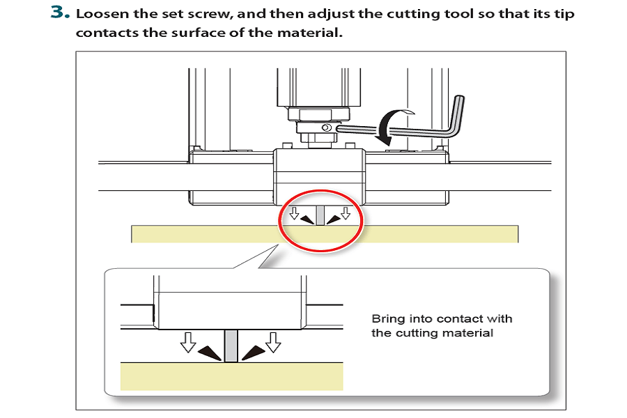
- Loosen the set screw, and then adjust the cutting tool so that its tip contacts the surface of the material.
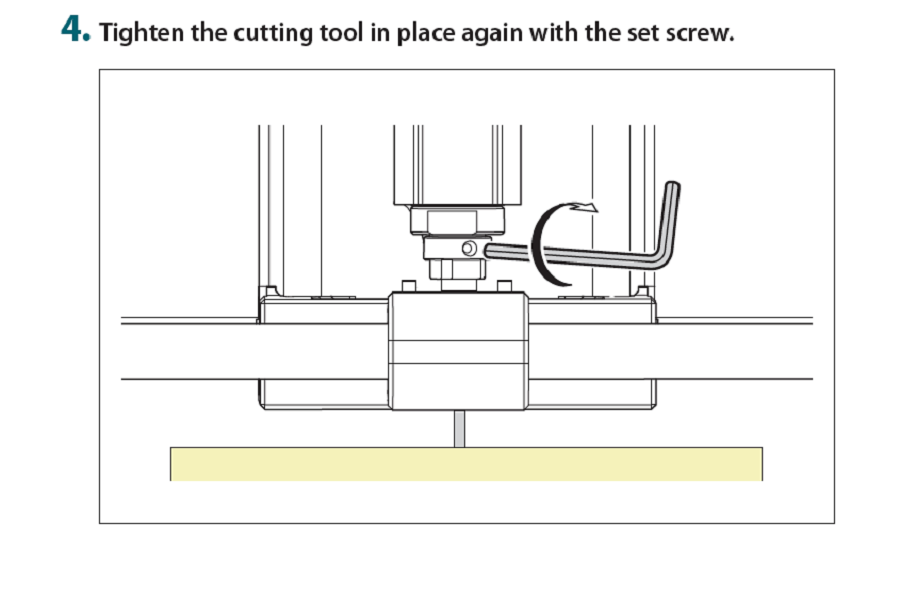
- Tighten the cutting tool in place again with the set screw.
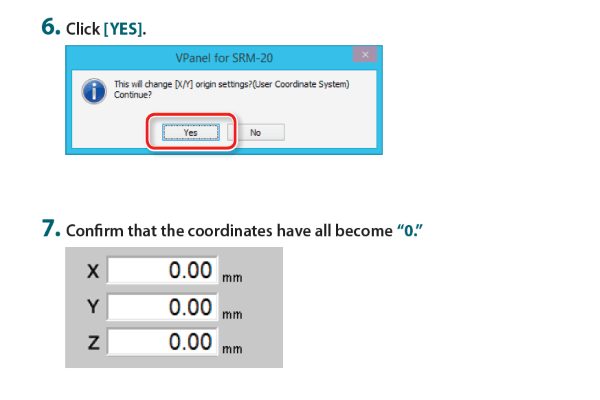
- Click [YES] and Confirm that the coordinates have all become 0.
5. Generate the tool path for tracing and cutting:

- Selected the trace PNG file first as shown in the picture below. We then set-up Zero for X, Y and Z absolute coordinate system.
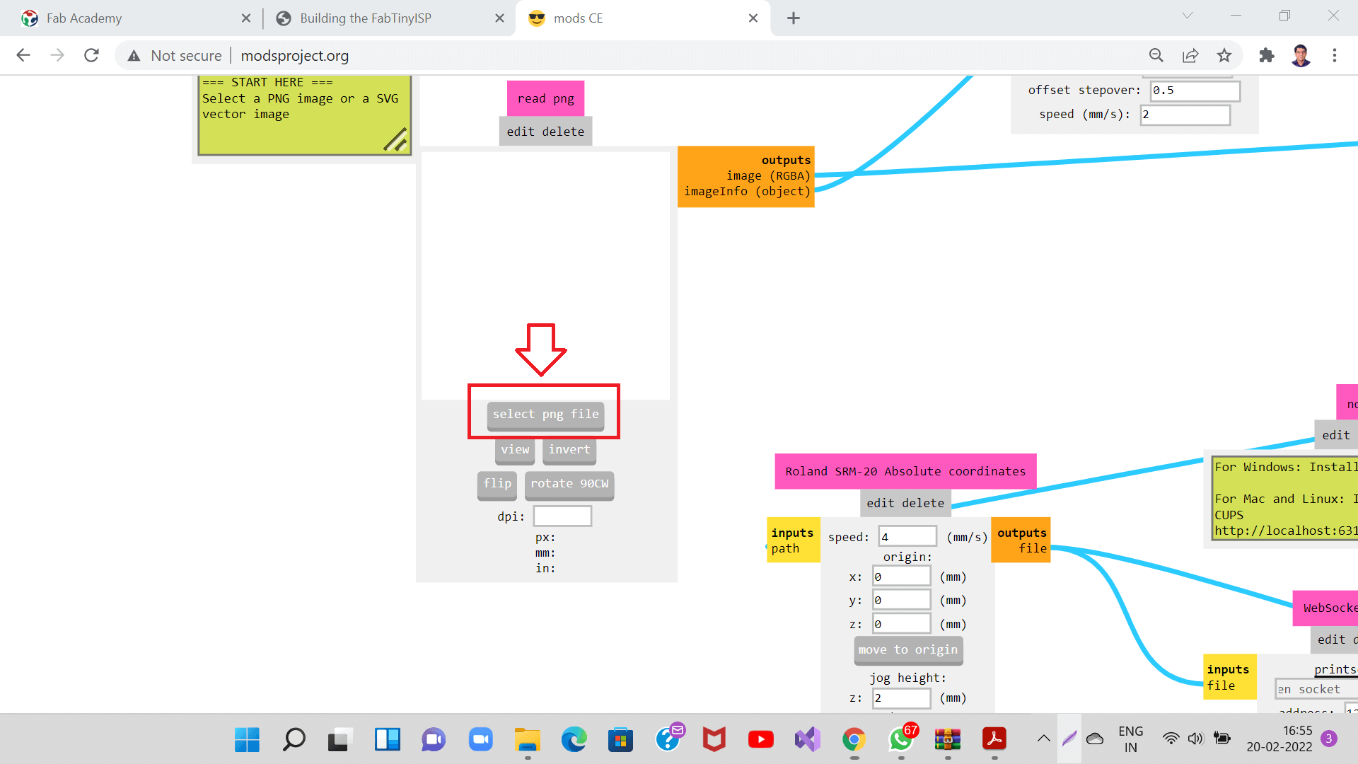
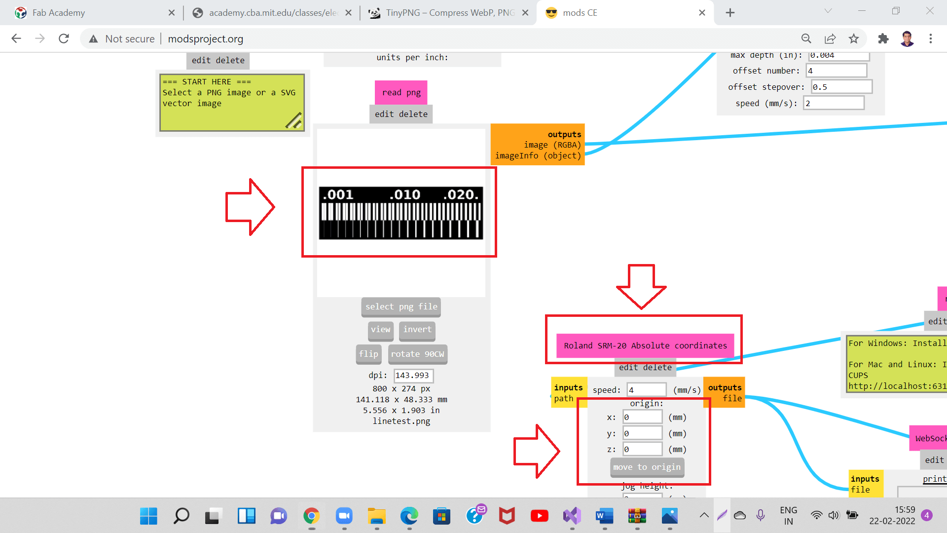
- We then connected output file of machine absolute coordinate to the 'save file button'.
- We then clicked 'calculate' button under 'mill raster 2D'. Then tool path for tracing was generated and got downloaded automatically as shown in the picture below. We will use this tool path in VPanel controller to be sent to the milling machine to start tracing.
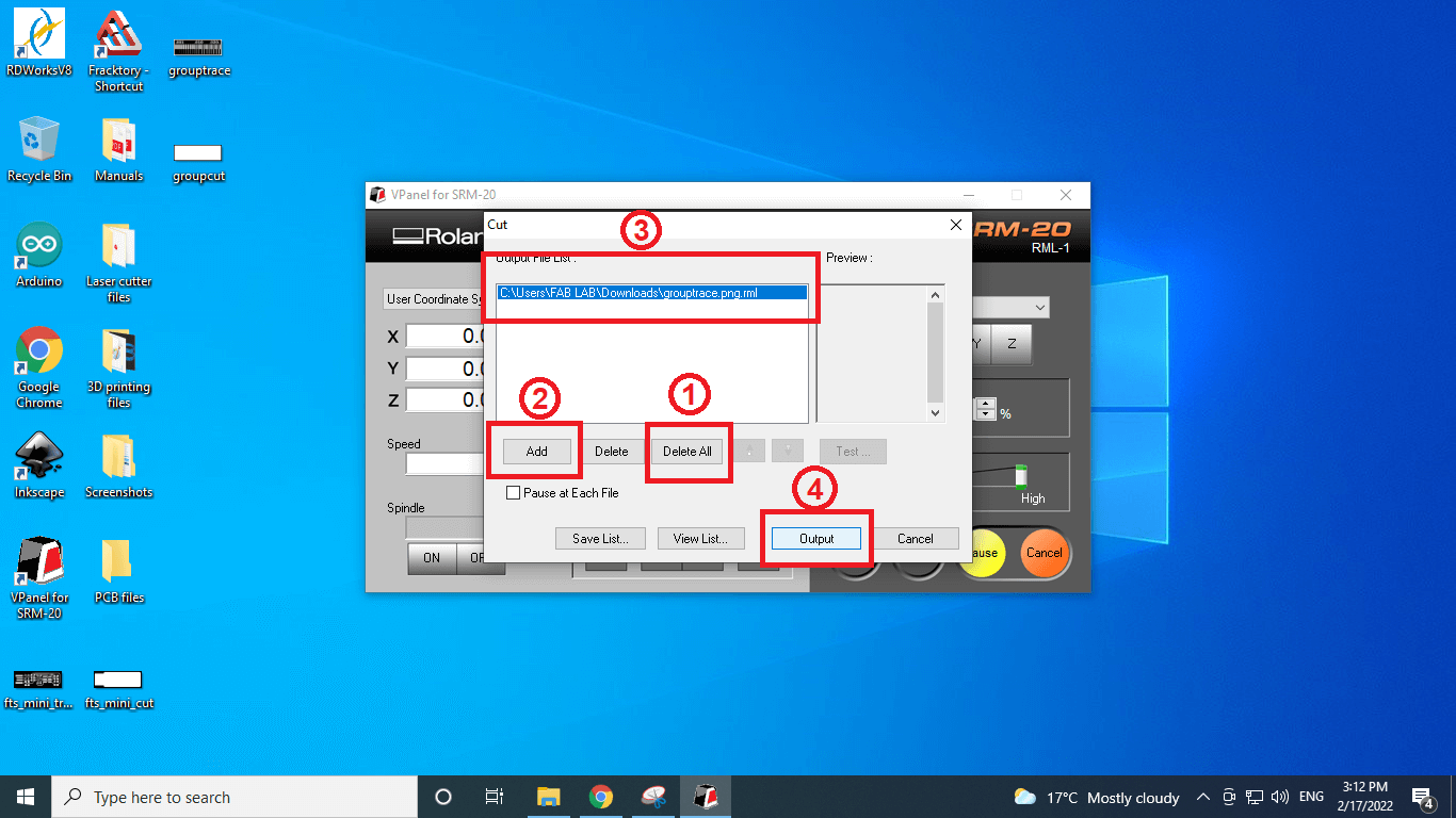
- We then deleted any previous paths and added new path. Selecting the newly added toolpath, I clicked on 'output' button to start the tracing operation inside the machine.
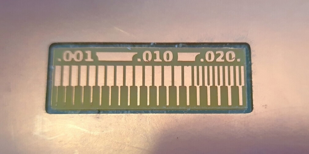
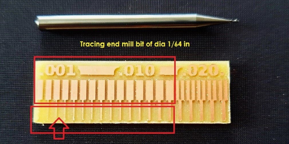
Conclusion from this assignment:
2. The minimum width of the trace has to be little more than the tool diameter. In our case, the tool diameter was 1/64 inch, i.e. 0.0156 inch. The traces were not cut properly, where the trace width is less than 0.0156 inch. Towards the left side of the board, where the trace widths are gradually decreasing, the tool could not cut the trace properly. The traces were removed off of the surface, which is not a good practice of machining PCB.Assembly of other Programmers like UPDI, FTDI and JTAG
Operate Vinyl Cutter for flexible PCB