
Assignment#12: Input Devices
This assignment is about documenting what I learned in Input Devices that includes types of input devices, their working principles and how to connect them to different microcontroller boards including the one that I made for this week. I have documented how I used my board with both input and output devices that I want to use in my final project. I was able to troubleshoot my board this week and I could program my board. I connected temperature, humidity and methane gas detection sensor. I am also documenting what went well, what went wrong, how I would do things differently in next assignment and my learning outcomes.
My Hero shots for this week
1. Connecting and Testing DS18B20 temperature sensor as an input device on my board
 |
 |
2. Connecting and Testing MQ2 gas sensor as an input device on my board
 |
 |
 |
My Hero videos for this week
1. Connecting and Testing DS18B20 temperature sensor as an input device on my board
2. Using DS18B20 temperature sensor as an input device and Relay as an Output device on my board
2. Connecting and Testing MQ2 gas sensor as an input device on my board
Click here to go back to the top
Basics of Input Devices
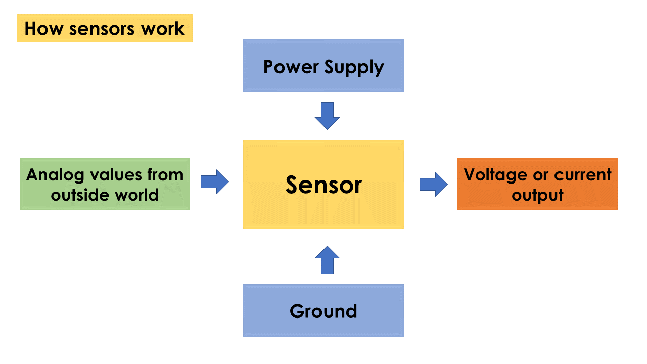
An input device responds to changes in the environment and produces a suitable electrical signal for processing in an electronic circuit. In all input devices, other forms of energy are transformed into electrical energy. In simple terms, a sensor is a device that detects changes and events in a physical stimulus and provides a corresponding output signal that can be measured and/or recorded. Here, the output signal can be any measurable signal and is generally an electrical quantity. The sensor is an element that produces signals relating to the quantity that is being measured. According to Instrument Society of America- a sensor is a device that provides usable output in response to a specified quantity which is measured. The word sensor is derived from the original meaning 'to perceive'. Sensors are devices that perform input function in a system as they 'sense' the changes in a quantity. The best example of a sensor is mercury thermometer. Here the quantity that is being measured is heat or temperature. The measured temperature is converted to a readable value on the calibrated glass tube, based on the expansion and contraction of liquid mercury.
The signal produced by the sensor is equivalent to the quantity to be measured. Sensors are used to measure a particular characteristic of any object or device. For example a thermocouple, a thermocouple will sense heat energy (temperature) at one of its junction and produce equivalent output voltage which can be measured by a voltage read by the voltmeter. All sensors need to be calibrated with respect to some reference value or standard for accurate measurement. Note that a transducer and a sensor are not the same. In the above given example of thermocouple. The thermocouple acts as a transducer but the additional circuits or components needed like the voltmeter, a display etc together from a temperature sensor. Hence the transducer will just convert the energy from one form to another and all the remaining work is done by the additional circuits connected. This whole device forms a sensor. Sensors and transducers are closely related to each other.
References: Reference#1, Reference#2, Reference#3
 |
 |
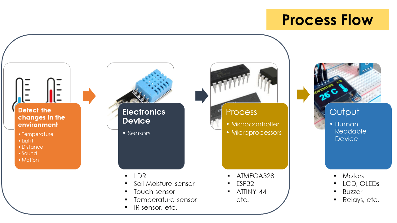 |
The world is full of sensors. In our day-to-day life, we come across automation in all the activities. Automation includes turning on lights and fans using mobile phones, controlling TV using mobile apps, adjusting the room temperature, smoke detectors, etc. All these are done with help of sensors. These days, any embedded system based product has inbuilt sensors in it. There are many applications like Mobile controlled CCTV camera, weather monitoring and prediction apps, etc. Sensors play a very vital role in Healthcare monitoring and detection. Therefore, before building an application-using sensor, we must understand what exactly does a sensor do and how many types of sensors are available.
Characteristics of Sensors
A good sensor should have the following characteristics:
- High Sensitivity: Sensitivity indicates how much the output of the device changes with unit change in input (quantity to be measured). For example the voltage of a temperature sensor changes by 1mV for every 1 Deg C change in temperature than the sensitivity of the sensor is said to be 1mV/Deg C.
- Linearity: The output should change linearly with the input.
- High Resolution: Resolution is the smallest change in the input that the device can detect.
- Less Noise and Disturbance.
- Less power consumption.
Sensor classification
1. Based on the quantity being measured, sensors are classified in to:
- Temperature: Resistance Temperature Detector (RTD), Thermistor, Thermocouple
- Pressure: Bourdon tube, manometer, diaphragms, pressure gauge
- Force/ torque: Strain gauge, load cell
- Speed/ position: Tachometer, encoder, LVDT
- Light: Photo-diode, Light dependent resistor.
2. Active and passive sensors: Based on power requirement sensors can be classified as active and passive.
- Active sensors: are those which do not require external power source for their functioning. They generate power within themselves to operate and hence called as self-generating type. The energy for functioning is derived from the quantity being measured. For example piezoelectric crystal generate electrical output (charge) when subjected to acceleration.
- Passive sensors: require external power source for their functioning. Most of the resistive, inductive and capacitive sensors are passive (just as resistors, inductors and capacitors are called passive devices).
3. Analog and digital sensor: An analog sensor converts the physical quantity being measured to analog form (continuous in time). Thermocouple, RTD, Strain gauge are called analog sensors. A digital sensor produces output in the form of pulse. Encoders are example of digital sensors.
4. Inverse sensors: There are some sensors which are capable of sensing a physical quantity to convert it to other form and also sense the output signal form to get back the quantity in original form. For example a piezoelectric crystal when subjected to vibration generates voltage. At the same time when a piezo crystal is subjected to varying voltage they begin to vibrate. This property make them suitable to use in microphone and speakers. Before I write what I did in this week of input devices, I am going to write about some of the sensors that I am going to evaluate for my project. We remember from our school science classes that the movement of molecules and atoms produces heat (kinetic energy) and the greater the movement, the more heat that is generated. Temperature Sensors measure the amount of heat energy or even coldness that is generated by an object or system, allowing us to 'sense' or detect any physical change to that temperature producing either an analogue or digital output. The two basic types of contact or even non-contact temperature sensors can also be sub-divided into the following three groups of sensors, Electro-mechanical, Resistive and Electronic and all three types are discussed below.
Source: Reference
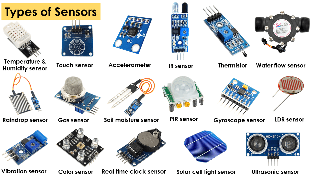
Types of Sensors
1. Temperature Sensors
A temperature sensor is an electronic device that measures the temperature of its environment and converts the input data into electronic data to record, monitor, or signal temperature changes. There are many different types of temperature sensors. Some temperature sensors require direct contact with the physical object that is being monitored (contact temperature sensors), while others indirectly measure the temperature of an object (non-contact temperature sensors). These types of temperature sensor use convection and radiation to monitor changes in temperature. They can be used to detect liquids and gases that emit radiant energy as heat rises and cold settles to the bottom in convection currents or detect the radiant energy being transmitted from an object in the form of infra-red radiation (the sun).
1. The Thermostat: The Thermostat is a contact type electro-mechanical temperature sensor or switch, that basically consists of two different metals such as nickel, copper, tungsten or aluminium etc, that are bonded together to form a Bi-metallic strip. The different linear expansion rates of the two dissimilar metals produces a mechanical bending movement when the strip is subjected to heat. The bi-metallic strip can be used itself as an electrical switch or as a mechanical way of operating an electrical switch in thermostatic controls and are used extensively to control hot water heating elements in boilers, furnaces, hot water storage tanks as well as in vehicle radiator cooling systems.
Source: Reference
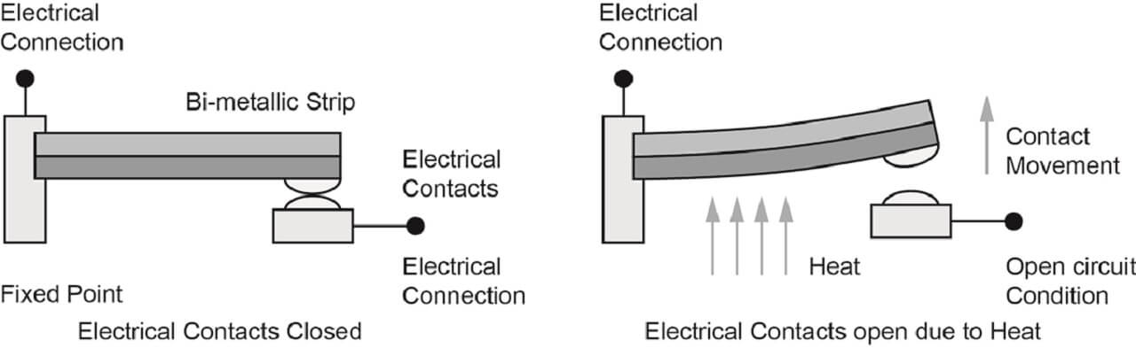
Image Source: Reference
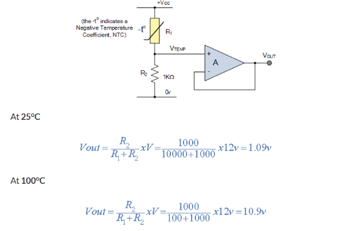
2. The Thermistor: The Thermistor is another type of temperature sensor, whose name is a combination of the words THERM-ally sensitive res-ISTOR. A thermistor is a special type of resistor which changes its physical resistance when exposed to changes in temperature. Thermistors are generally made from ceramic materials such as oxides of nickel, manganese or cobalt coated in glass which makes them easily damaged. Their main advantage over snap-action types is their speed of response to any changes in temperature, accuracy and repeatability.
Most types of thermistors have a Negative Temperature Coefficient of resistance or (NTC), that is their resistance value goes DOWN with an increase in the temperature, and of course there are some which have a Positive Temperature Coefficient, (PTC), in that their resistance value goes UP with an increase in temperature.
The following thermistor has a resistance value of 10KOhm at 25 Deg C and a resistance value of 100 Ohm at 100 Deg C. Calculate the voltage drop across the thermistor and hence its output voltage (Vout) for both temperatures when connected in series with a 1 kOhm resistor across a 12V power supply.
 |
3. Resistive Temperature Detectors (RTD): Another type of electrical resistance temperature sensor is the Resistance Temperature Detector or RTD. RTDs are precision temperature sensors made from high-purity conducting metals such as platinum, copper or nickel wound into a coil and whose electrical resistance changes as a function of temperature, similar to that of the thermistor.
Resistive temperature detectors have positive temperature coefficients (PTC) but unlike the thermistor their output is extremely linear producing very accurate measurements of temperature. However, they have very poor thermal sensitivity, that is a change in temperature only produces a very small output change for example, 1Ohm/Deg C.
Source: Reference
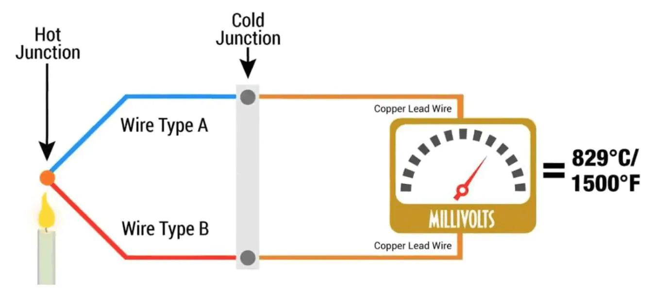
4. Thermocouples: The Thermocouple is by far the most commonly used type of all the temperature sensor types. Thermocouples are popular due to its simplicity, ease of use and their speed of response to changes in temperature, due mainly to their small size. Thermocouples also have the widest temperature range of all the temperature sensors from below -200 Deg C to well over 2000 Deg C.
Thermocouples are thermoelectric sensors that basically consists of two junctions of dissimilar metals, such as copper and constantan that are welded or crimped together. One junction is kept at a constant temperature called the reference (Cold) junction, while the other the measuring (Hot) junction. When the two junctions are at different temperatures, a voltage is developed across the junction which is used to measure the temperature sensor as shown below.
Source: Reference
 |
DS18B20 Temperature sensor
The DS18B20 is a 1-wire programmable Temperature sensor from maxim integrated. It is widely used to measure temperature in hard environments like in chemical solutions, mines or soil etc. The constriction of the sensor is rugged and also can be purchased with a waterproof option making the mounting process easy. It can measure a wide range of temperature from -55 Deg C to +125 Deg C with a decent accuracy of +/- 0.5 Deg C. Each sensor has a unique address and requires only one pin of the MCU to transfer data so it a very good choice for measuring temperature at multiple points without compromising much of your digital pins on the microcontroller. This is an advanced level protocol, where each sensor can be set with a 64-bit serial code which aids to control numerous sensors using a single pin of the microcontroller.
It supplies 9-bit to 12-bit readings of temperature. These values show the temperature of a particular device. The communication of this sensor can be done through a one-wire bus protocol which uses one data line to communicate with an inner microprocessor. Additionally, this sensor gets the power supply directly from the data line so that the need for an external power supply can be eliminated. The applications of the DS18B20 temperature sensor include industrial systems, consumer products, systems which are sensitive thermally, thermostatic controls, and thermometers.
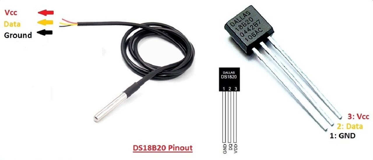
DS18B20 Pin Configuration
-Pin1 (Ground): This pin is used to connect to the GND terminal of the circuit
-Pin2 (Vcc): This pin is used to give the power to the sensor which ranges from 3.3V or 5V
-Pin3 (Data): The data pin supplies the temperature value, which can communicate with the help of 1-wire method.
 |
DS18B20 Specifications
- This sensor is a programmable and it is a digital temperature sensor
- Communication of this sensor can be done with the help of a 1-Wire method
- Range of power supply is 3.0V - 5.5V
- The accuracy of this sensor is +/- 0.5 Deg C
- Output resolution ranges from 9-bit to 12-bit
- This sensor can be power-driven from the data line
- These are obtainable like SOP, To-92, and also as a waterproof sensor
- The temperature can be calculated from -55 Deg C to +125 Deg C
DS18B20 Datasheet Reference Source: Click here
MQ2 Gas sensor
Before I write more about MQ2 gas sensor, I will start with general working principle of gas sensors. Inside gas sensor, there is a chemi-resistor, which changes the resistance based on its sensing material. Following picture explains this functionality. Reference
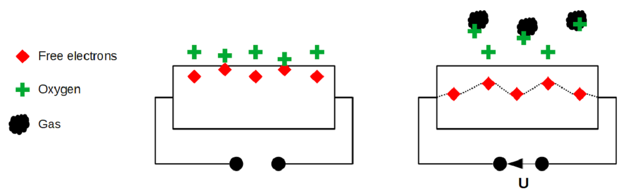 |
In most of the cases, the sensing material is tin dioxide (SnO2), which has free-electrons inside. Oxygen outside attracts these free electrons towards the surface of sensing material (picture on the left side above). when the oxygen is absorbed on the material, there are no free electrons available in the tin dioxide. This results in: without free electrons, there is no electrical current flow inside. Whereas, in an environment having toxic or combustible gases, this gas breaks the connection between the absorbed oxygen on the surface and the electrons (picture on the right side above). These released electrons are now free and they get back to their initial position, where they enable the current flow. Intensity of current flow depends on the amount of free electrons available in the SnO2, which is proportional to the concentration of toxic or combustible gases.
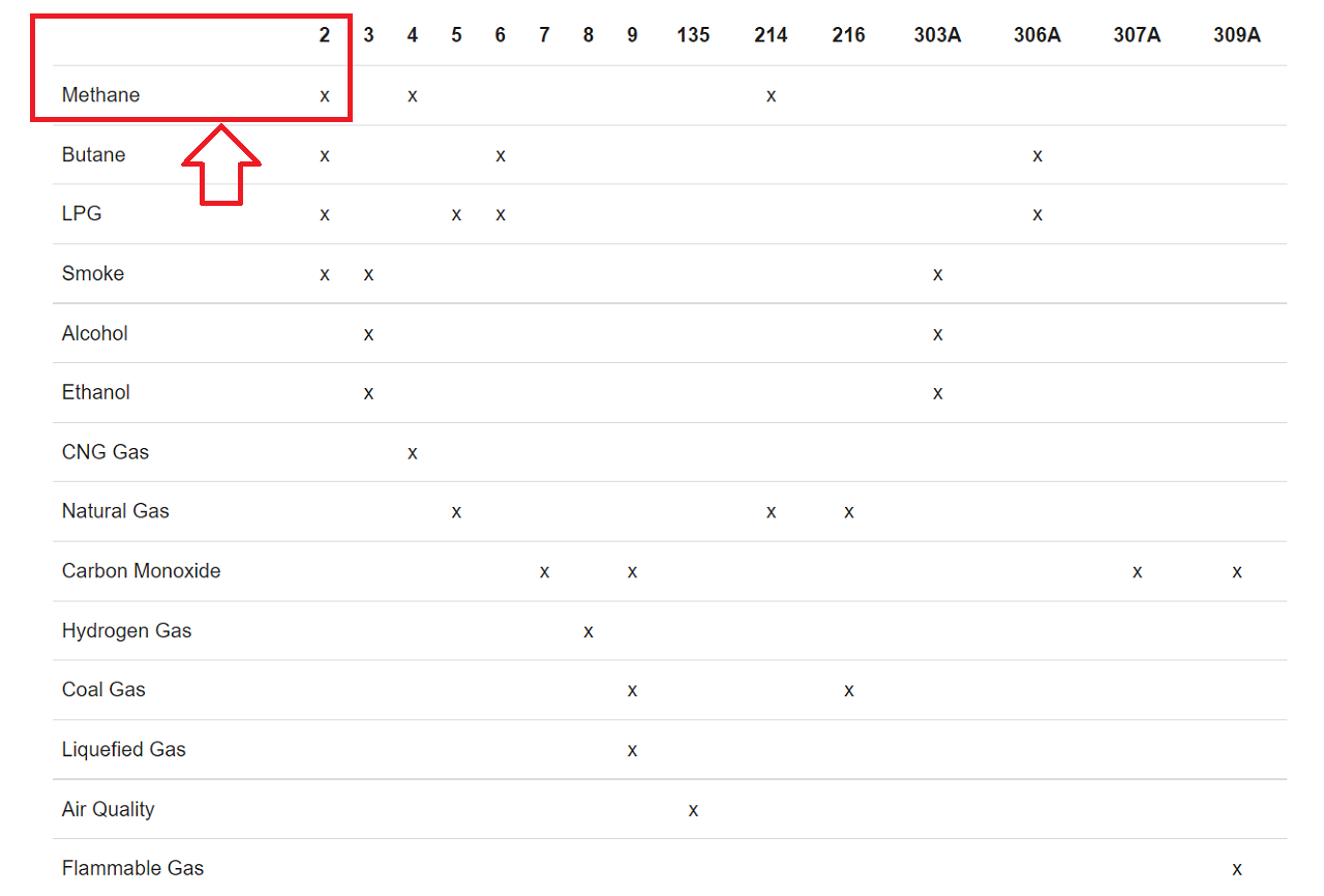
According to the Ohms law, a higher current flow results in a higher potential difference, which can be measured as output voltage on the analog output of the sensor, using a simple voltage divider network. Therefore, the concentrations of gas can be measured. The type of sensor is defined by the sensing material inside the sensor. Although some of the gas sensors are sensitive to multiple gases, the sensor can not identify which of the gases are in higher concentration. I referred the following table that gives us an overview about the different gas sensors that are available and what gasses they are able to detect. Since I want to detect methase gas, I selected MQ2 gas sensor for my project.
 |
Before I start using the MQ2 gas sensor for my project, I needed to know more about this sensor, the whole module along with all other electronic components. Therefore, I went through the technical datasheet of the entire module and how the MQ2 gas sensor is measuring the gas concentration. Then, I went through the electronic components on the senor module along with its pinout.
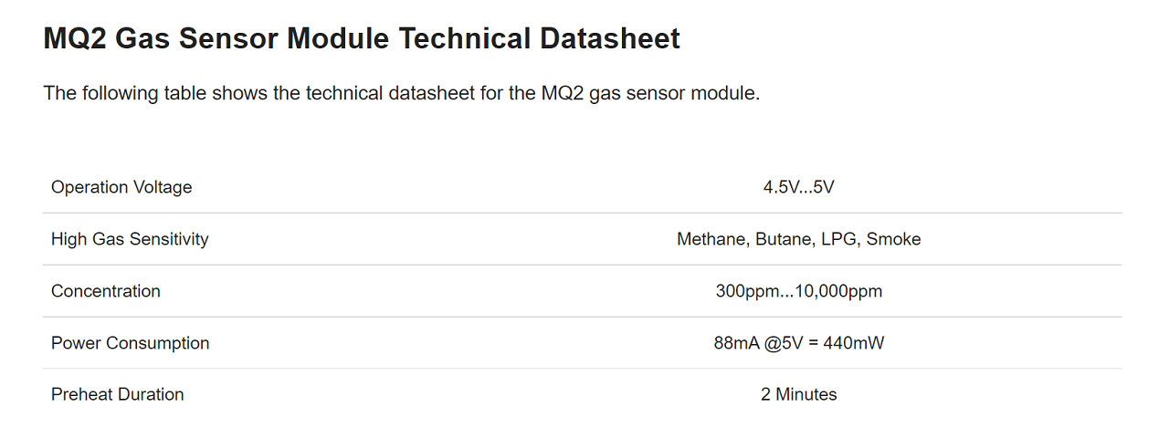 |
The operating voltage of MQ2 gas sensor is between 4.5V and 5V. This sensor is also used as heater for the surface of the SnO2. Therefore, the microcontroller I am going use in my project (which is ESP32) needs to provide a stable 5V output. I have to power my ESP32 board via USB or an external power supply to get an 5V output. The MQ2 gas sensor is sensitive to LPG, methane, butane and smoke in general. These gases can be measured in concentrations between 300 ppm and 10,000 ppm. Because it takes some time until the surface is hot, the MQ2 gas sensor has a preheat duration of around 2 minutes and has a current consumption of 88mA also during the preheat duration. With a 5V supply voltage, the MQ2 gas sensor has a power consumption of 440mW.
MQ2 Pin Configuration
The following picture below shows the back side of the MQ2 gas sensor module board.
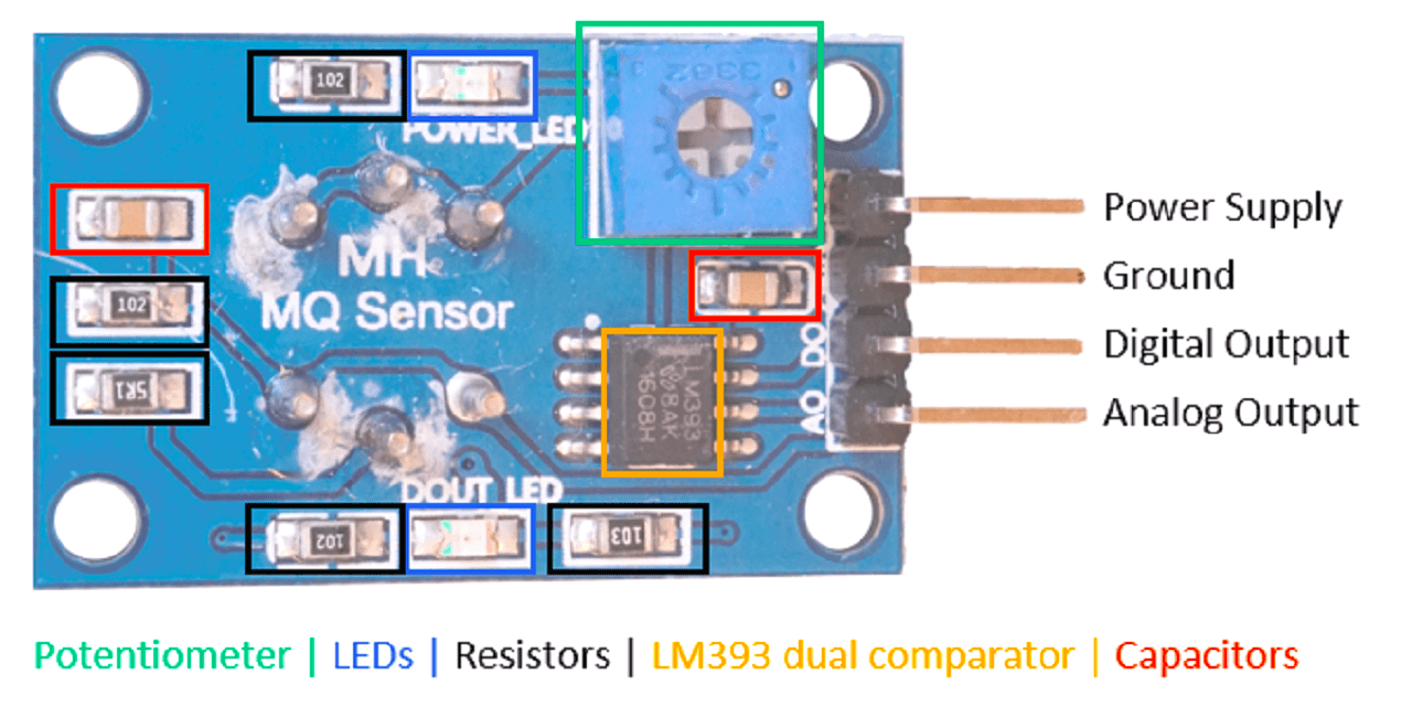 |
This module consists of the following electronic parts:
- 4 output pins that connect the gas sensor to a microcontroller:
1. A0: Analog pin to transfer an analog signal.
2. GND: Ground to connect the gas sensor to ground with the microcontroller.
3. VCC: Pin for the 5V operation voltage
4. D0: Digital output based on a predefined threshold through the potentiometer and the operation voltage of the microcontroller.
- 2. Potentiometer to define a threshold for the digital output pin.
- 2 LEDs to indicate that the module is operating (POWER_LED) and to indicate the status of the digital pin (DOUT_LED).
- 5 Resistors to prevent LEDs for too high voltages and to operate as voltage dividers.
- LM393 dual comparator to compare the signal created by the MQ2 gas sensor with the predefined value through the potentiometer and to control the status of the LED that indicates the status of the digital output.
- 2 Capacitors to filter the voltage and stabilize the input and output.
Functionality of the MQ2 Gas Sensor Module
The resistance of the MQ2 gas sensor decreases as the gas concentration that is measured increases. When the gas concentration increases, the voltage across the MQ2 sensor decreases because of the decrease of resistance (V=R*I). Because the voltage between VCC and GND needs to be the same, the voltage across the resistance increases and thus the potential on the point, where the analog value is measured. The analog sensor value increases due to the increase of gas concentration.
MQ2 Datasheet Reference Source: Click here
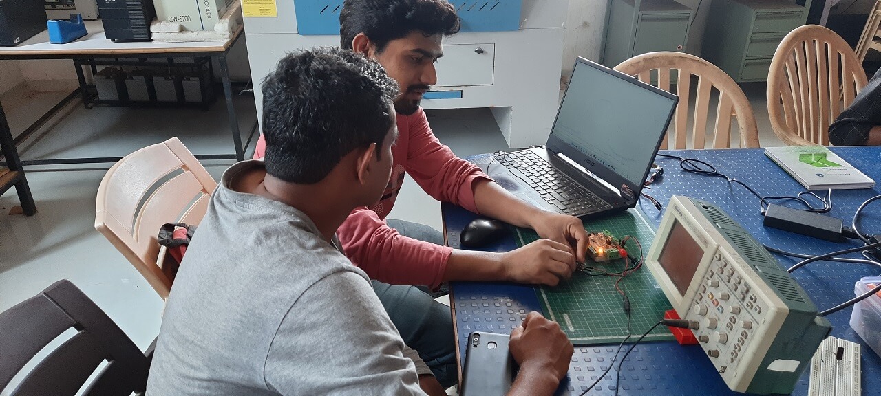
Group Assignment Brief
This assignment is about documenting what we learned in Input Devices week that includes understanding different sensors and probe an input device's analog levels and digital signals on one of the boards we made as a part of individual assignment for this week.
Objectives of the Group Assignment:
- Probe an input device's analog levels and digital signals
Input Device that we probed for it's analog and digital signals:
- IR sensor
- Potentiometer
To probe the digital signal of an input device, we connected IR sensor to the Input devices board and activated the sensor after programming the board through arduino IDE. First connected the board to DSO (Digital storage oscilloscope) and probed in to sensor's digital waves as shown below.
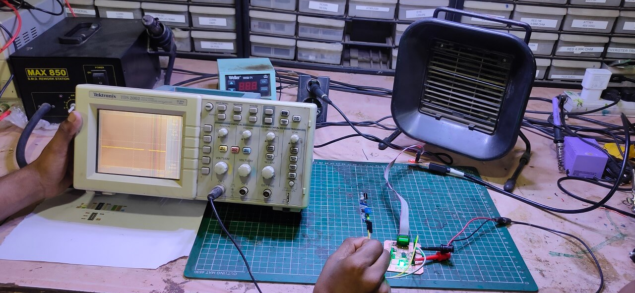 |
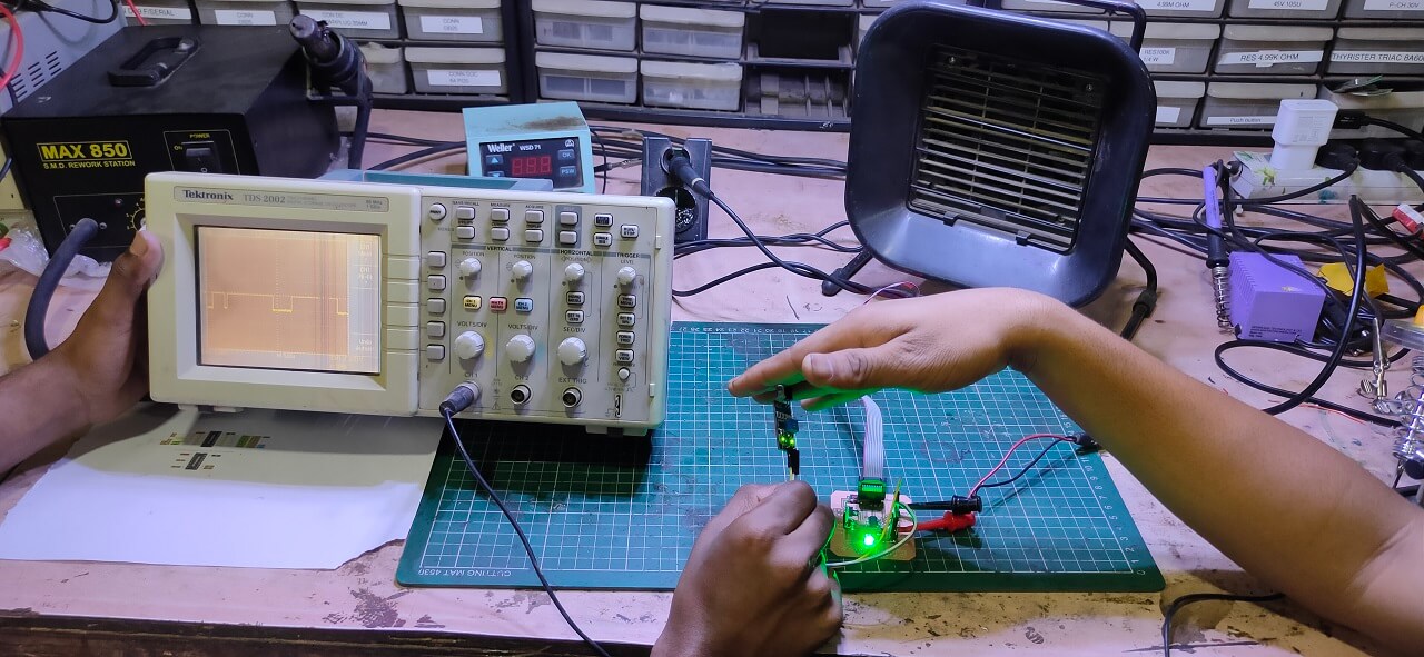 |
Later to probe the analog levels of an input device, we connected potentiometer to the Input devices board and progammed the board for analog read through arduino IDE. After that we connected the board to DSO (Digital storage oscilloscope) and probed in to sensor's analog levels waves as shown below.
 |
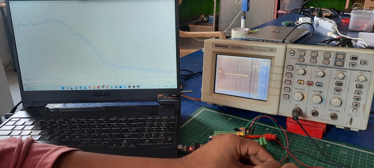 |
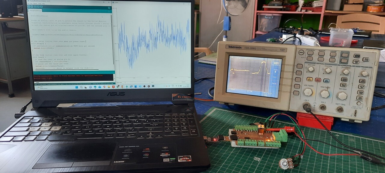 |
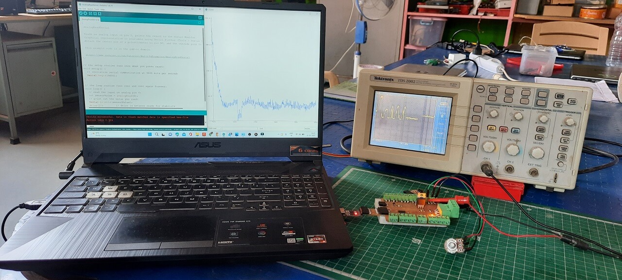 |
Click here to read more about our Group Assignment.
Click here to go back to the top
Individual Assignment
Objectives of Individual Assignment:
- Add a sensor to a microcontroller board that you have designed
- Measure something and read it.
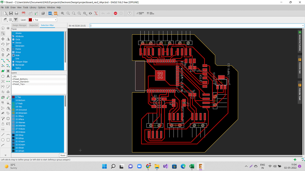
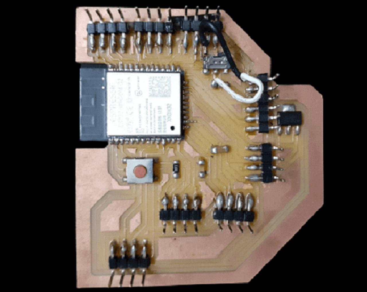
Design of my final project board
Last to last week I designed, milled and stuffed my final project board as well. I had made an attempt to program this board. However, I could not program it because of some issues that I had then. However, after troubleshooting and resolving the issue, I was able to program the board, connect both input and output devices to my board this week as explained below.
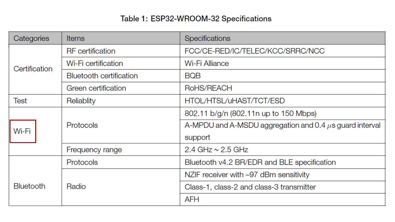
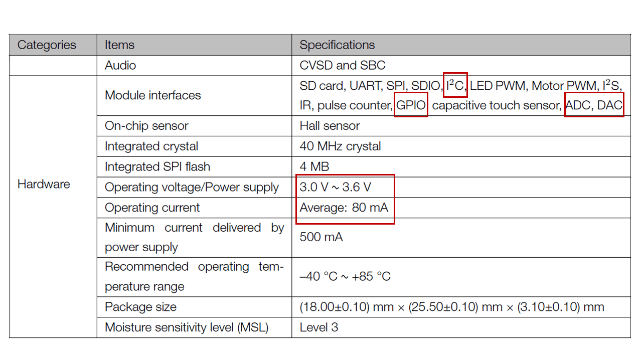
While designing my final project board, I referred ESP32-WROOM-32 Data sheet to find out the pin-out of the IC to design my board. Below are the important specifications I looked in to while selecting ESP32-Wroom32 micro-controller for my final project board.
 |
 |
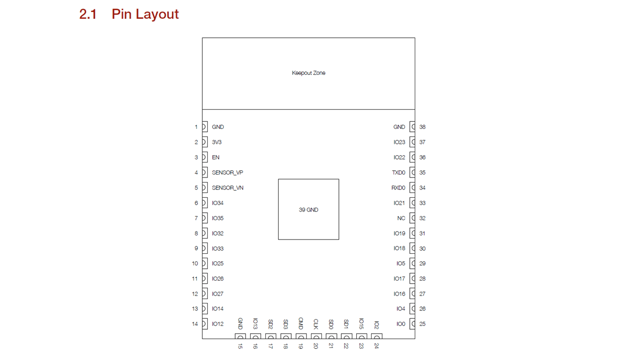
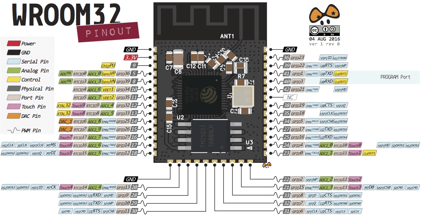
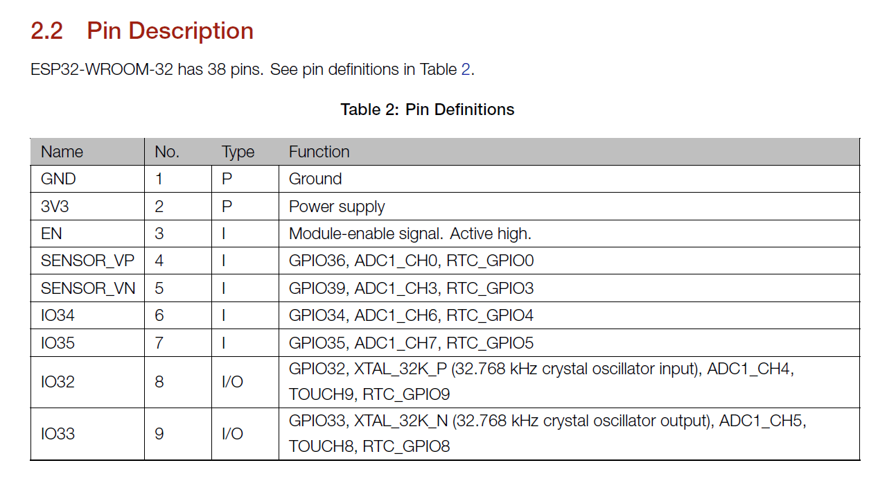
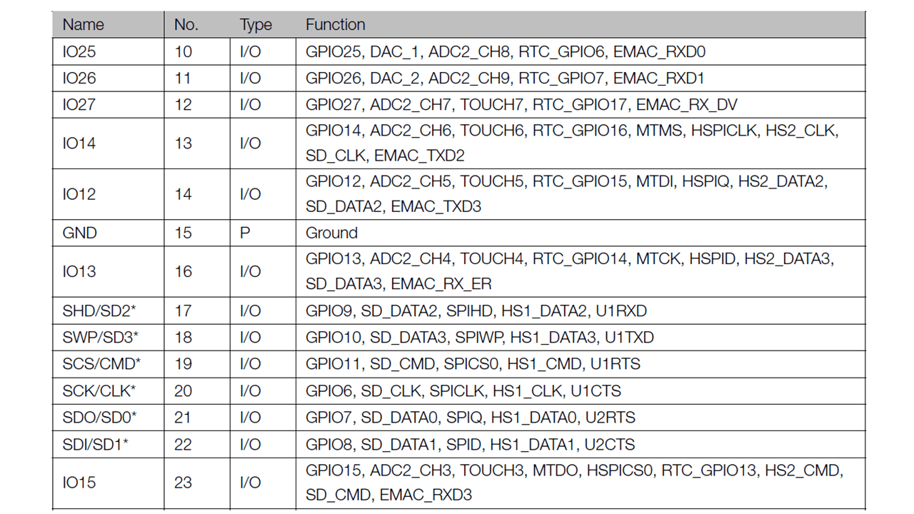
Below is the pin-out of ESP32-Wroom32. After understanding the pin-out and description of each pin from the datasheet, I chose pins for input and output devices that I will be connecting to my project board as shown below.
 |
 |
 |
 |
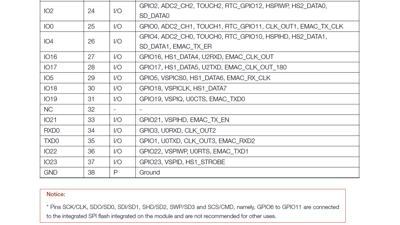 |
I then converted this table to an excel sheet for me to be able to map each pin to their respective input and output devices as shown below.
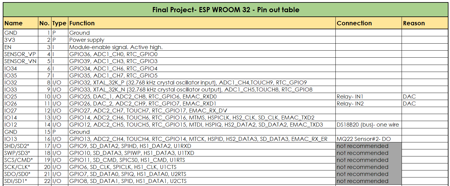 |
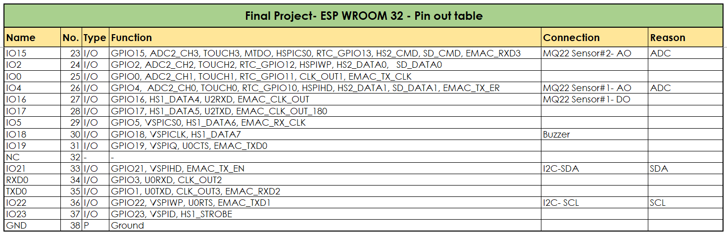 |
 |
 |
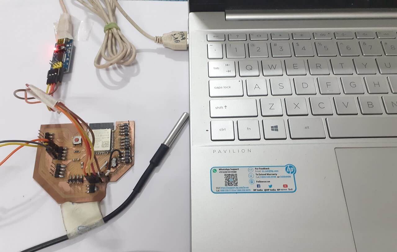
1. Connectiong DS18B20 temperature to my board
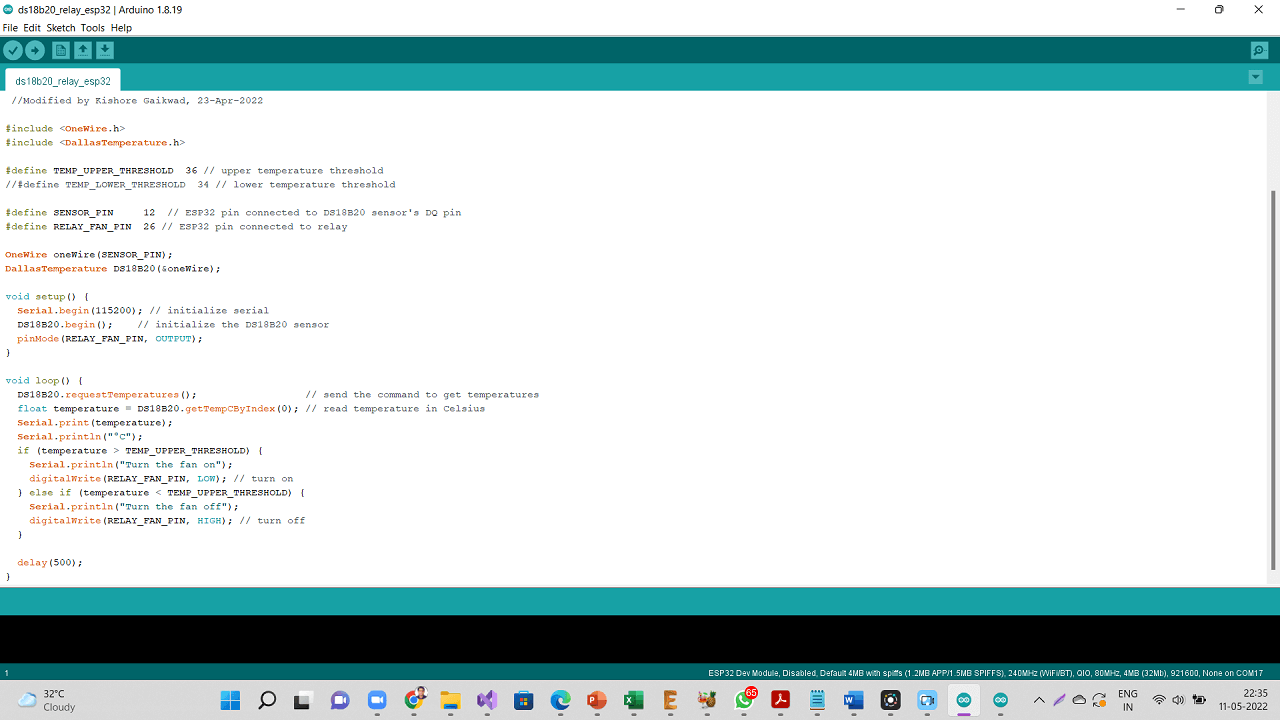
For this week's assignment, I connected DB18B20 temperature sensor to my project board as shown below. I programmed my board and measured temperature readings. This was done primarily to test my board, my program and the input device if it is working the way it is supposed to be.
 |
Click here to see/copy the DS18B20 basic program or download sketch from the cloud screen below.
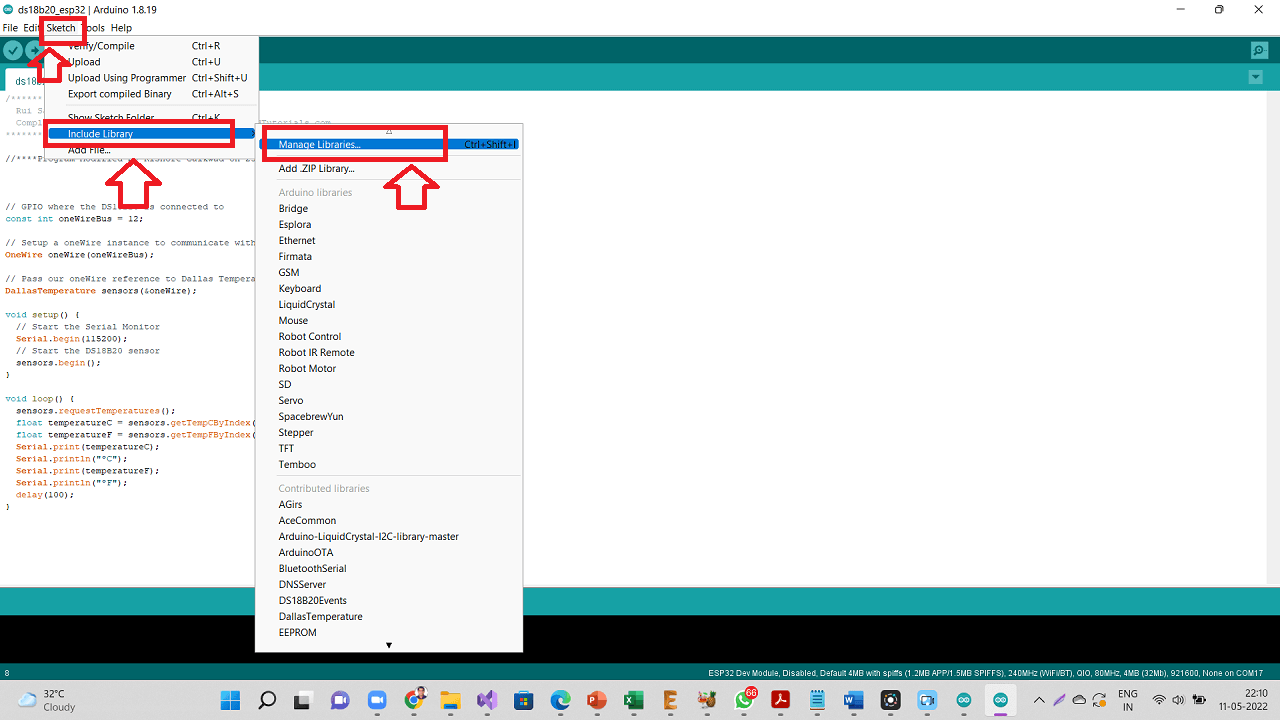
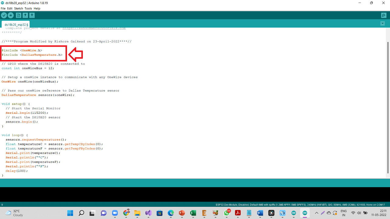
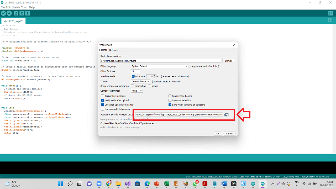
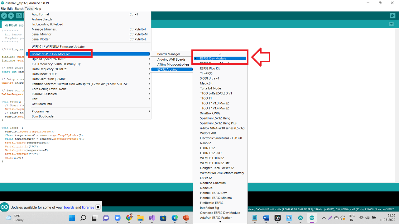
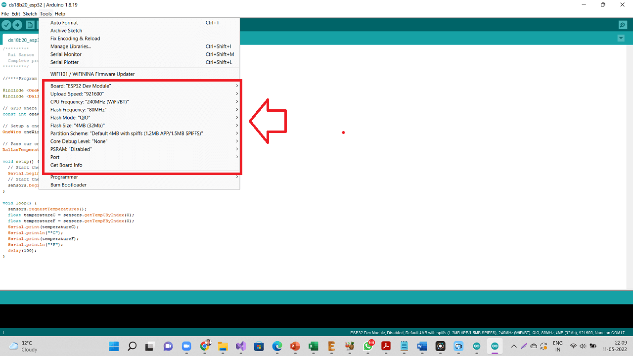
Following are the settings done in Arduino IDE. I also installed onewire.h and DallasTemperature.h libraries as shown below.
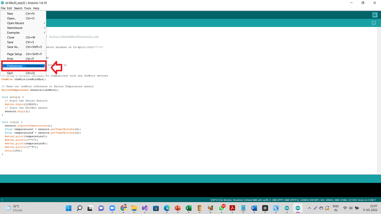
On Arduino IDE, Navigate to Sketch --> Include Library --> Manage Libraries
 |
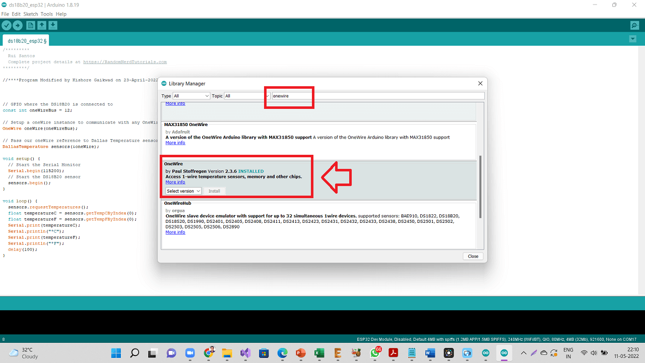
Type "OneWire" on the search box, then look for the OneWire library by Paul Stoffregen. Click Install button to install OneWire library.
 |
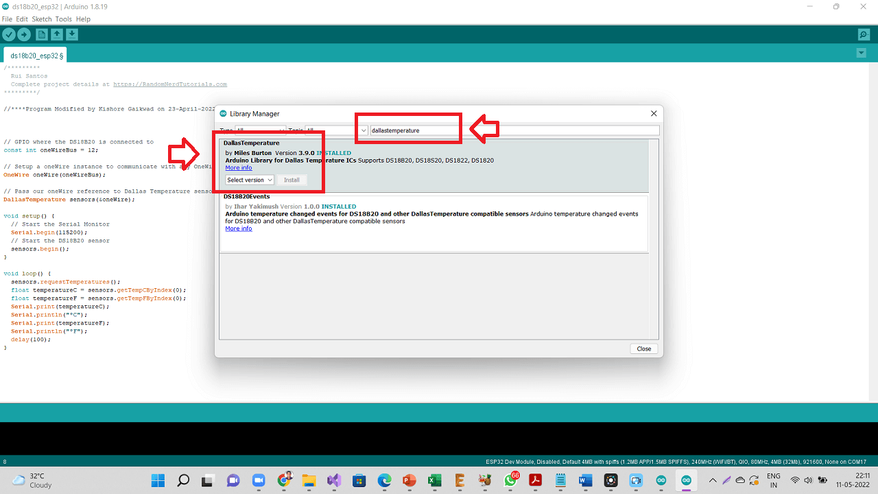
Type "dallastemperature" on the search box, then look for the "DallasTemperature" library by Miles Burton. Click Install button to install DallasTemperature library.
 |
 |
 |
 |
 |
 |
Following are the Temperature readings seen in Serial monitor.
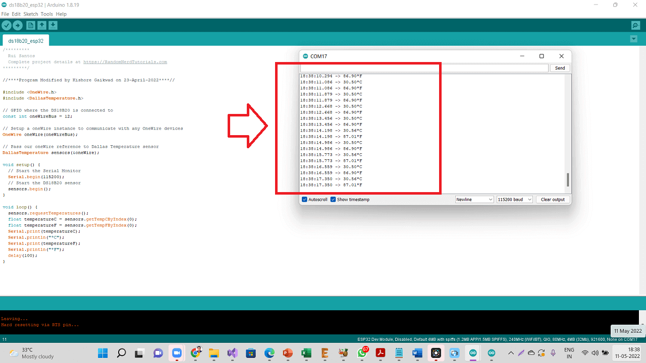 |
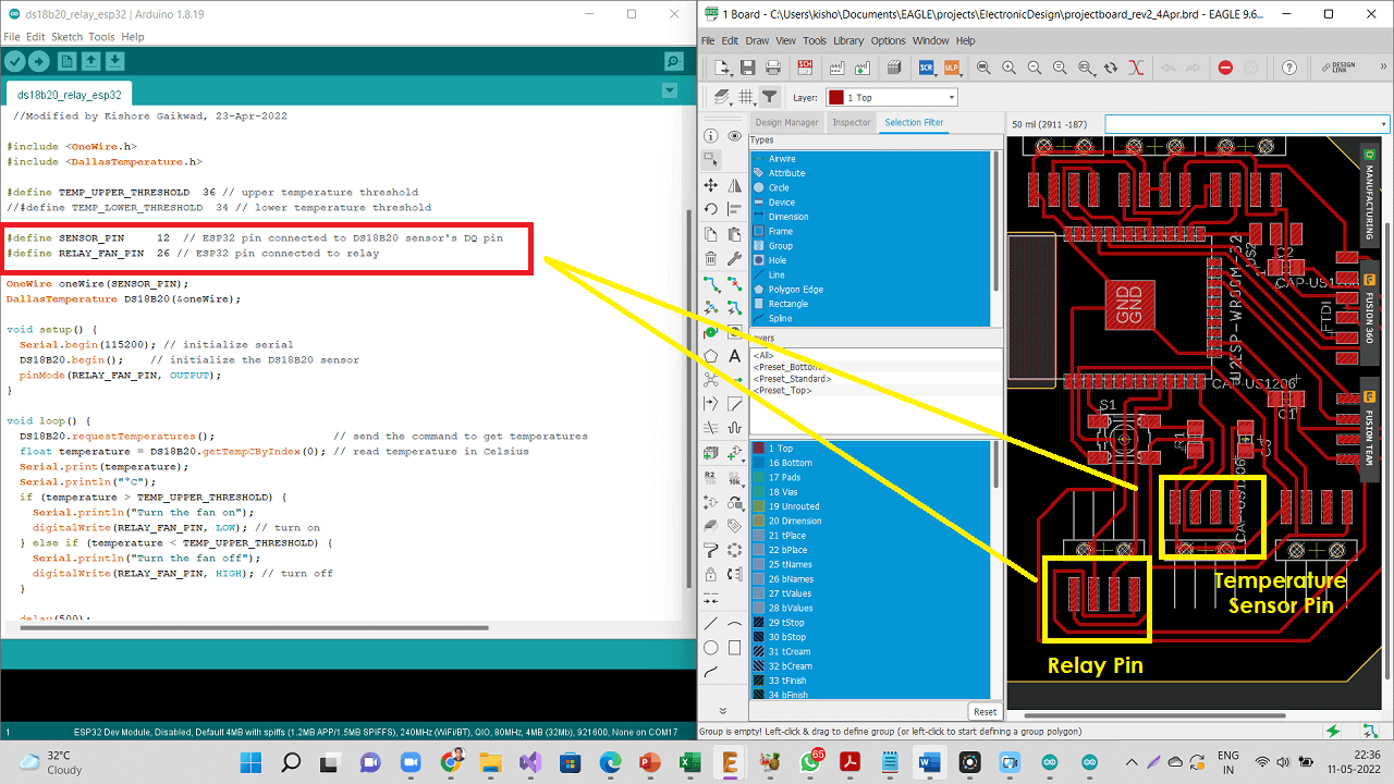
2. Connectiong DS18B20 temperature sensor and a relay to my board
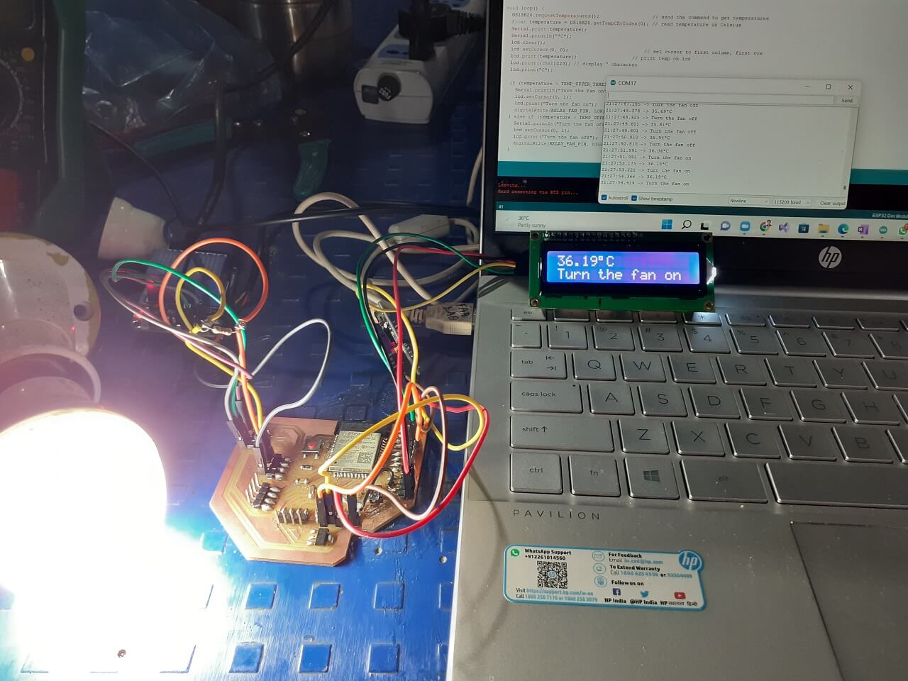
For the requirement of my final project, I connected one DS18B20 temperature sensor as an input device and a relay connected to an AC bulb as an output device to my final project board. I am going to connect an exhaust fan to the relay. However, for to check if the relay is working with the program and also to meet the purpose of this and previous assignment, I connected relay to AC bulb.
 |
Click here to see/copy the DS18B20 and Relay program or download sketch from the cloud screen below.
 |
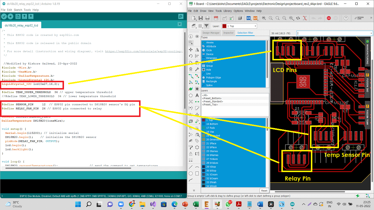
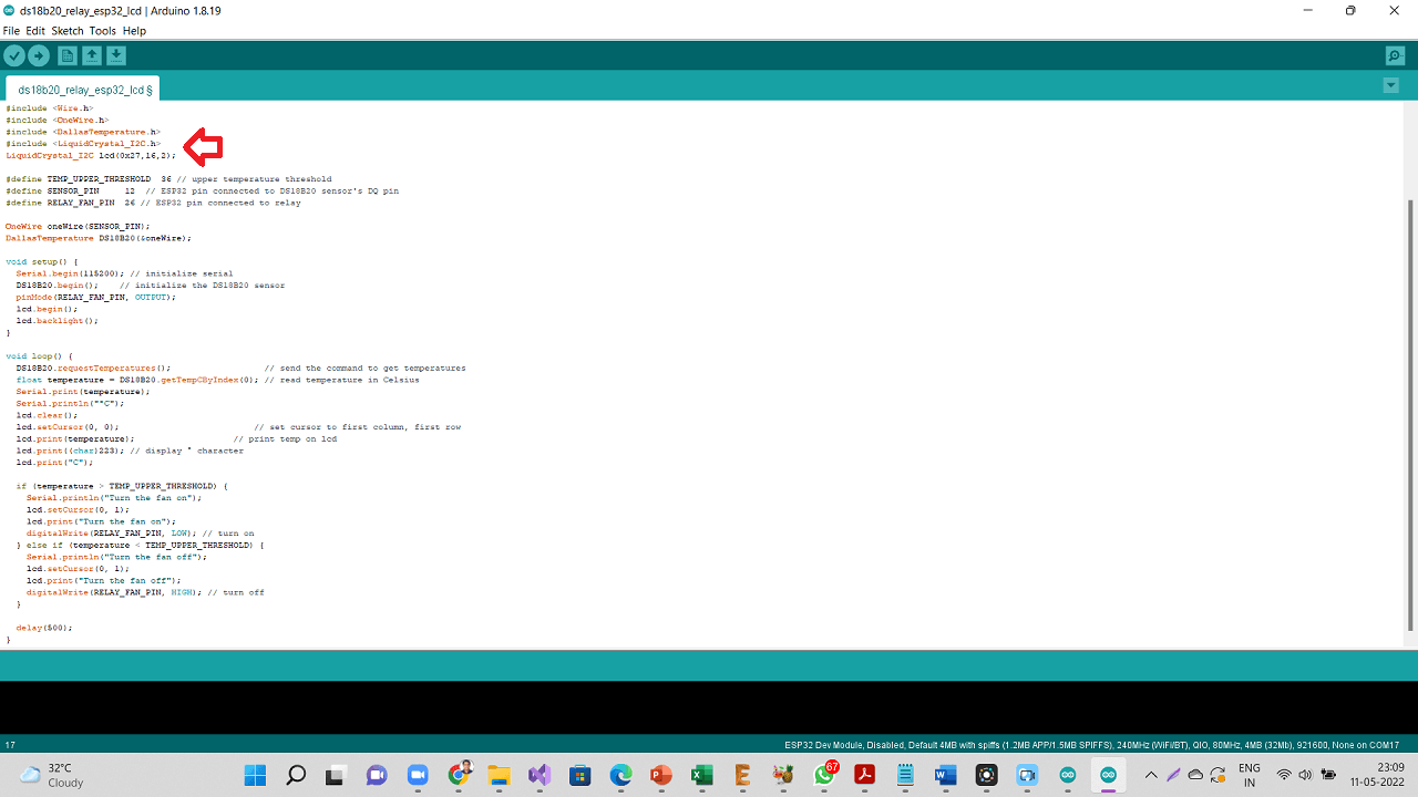
I also added an LCD screen as an output device to my board. I added "LiquidCrystal_I2C" library as shown below.
 |
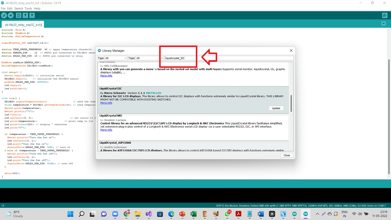 |
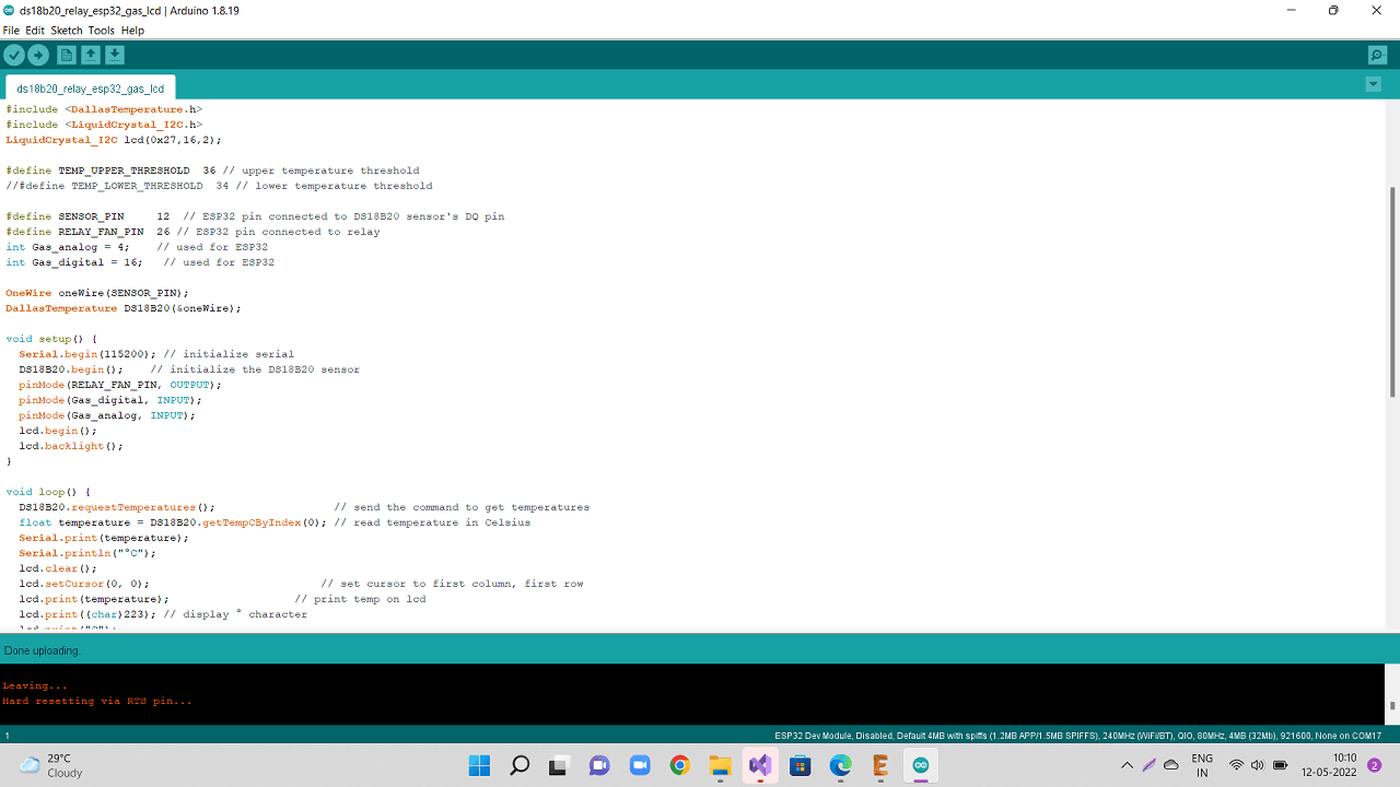
Click here to see/copy the DS18B20 and Relay program with LCD added or download sketch from the cloud screen below.
 |
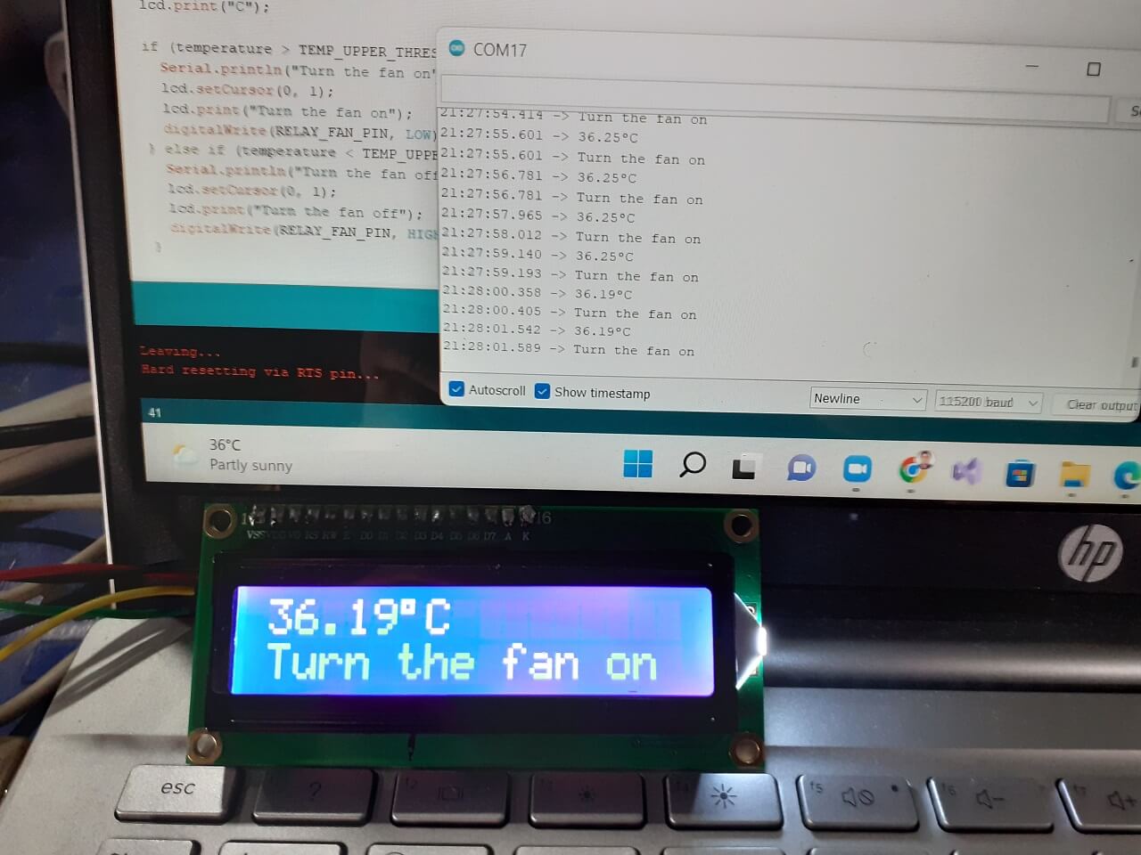
I have added an IF condition to the program. When the temperature reading from the sensor is above 36 Deg Celcius, the relay is going to be switched ON and it switches OFF below 36 Deg C.
|
|
Video: Connecting and testing DS18B20 temperature sensor:
3. Connectiong MQ2 Gas sensor to my board
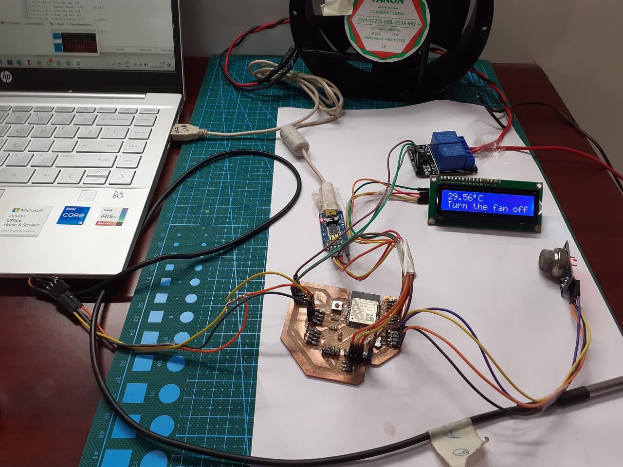
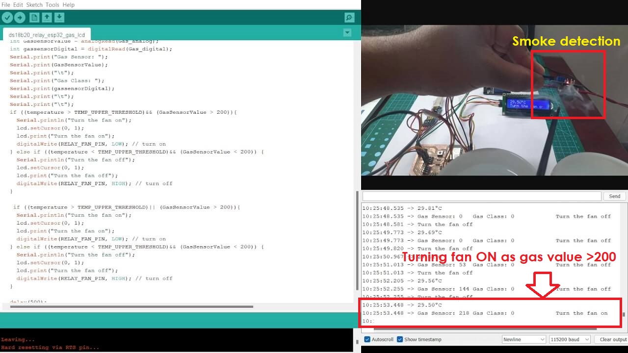
For the requirement of my final project, I also wanted to connect one MQ2 gas sensor as an input device to measure the methane gas concentration around the onions. As the onions in warehouse get rotten, they emit methane. So, I decided to connect on MQ2 gas sensor, which detects methane. As the methase gas level goes beyond a threshold value, the microcontroller will turn the relay and the exhaust fan ON. I therefore, first tried connecting MQ2 gas sensor along with the LCD display as shown below.
|
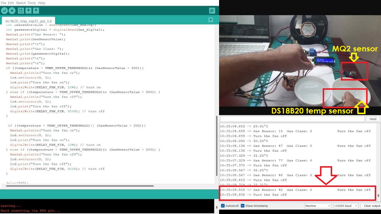
Click here to see/copy the DS18B20, MQ2 sensor, LCD and Relay program or download sketch from the cloud screen below.
 |
|
|
Click here to go back to the top
Download Original Files
Click here to download all original files.
Click here to go back to the topWhat went well
In group assignment- As a group, we went through various input devices. We could probe an input device's analog levels and digital signals
In individual assignment- I tried connecting input devices required for my final project to my final project board in this week and I was successful in it. Logic that I incorporated to control the exhaust fan in various conditions like temperature and gas values worked perfectly.
What went wrong
In group assignment- There is nothing major that we did wrong in the group assignment.
In individual assignment- I was struggling to integrate code for gas sensor with other input and output devices but I was able to figure that out.
What I would do differently
- I would have tried to using other temperature sensors.
- I would proble in to input device of my final project board.
Learning Outcomes
- I learned about different sensors and their working princliples
- I learned how to do programming for various input devices.
- I learned various sensors, their connections and specifially DS18B20 and MQ2 gas sensor that are required for my final project.
- I learned to integrate programs for diferent input and output devices in one single program.