
Assignment#15: Wildcard Week
This assignment is about documenting what I learned in the wildcard week. This week was to explore and learn processes that were not taught in the Fab academy so far. We had different options here in our Fab lab at Vigyan Ashram. I went through a couple of them and decided to work on Plasma cutting. Workshop in Vigyan ashram needed one sitting stool in their work area, so I decided to design workstool in solidworks sheet metal and then use plasma cutting machine to cut sheet metal, followed by bending, welding and painting processes. As a part of this assignment I have documented how I designed the part, used plasma cutting machine, etc. I am also documenting what went well, what went wrong, how I would do things differently in next assignment and my learning outcomes.
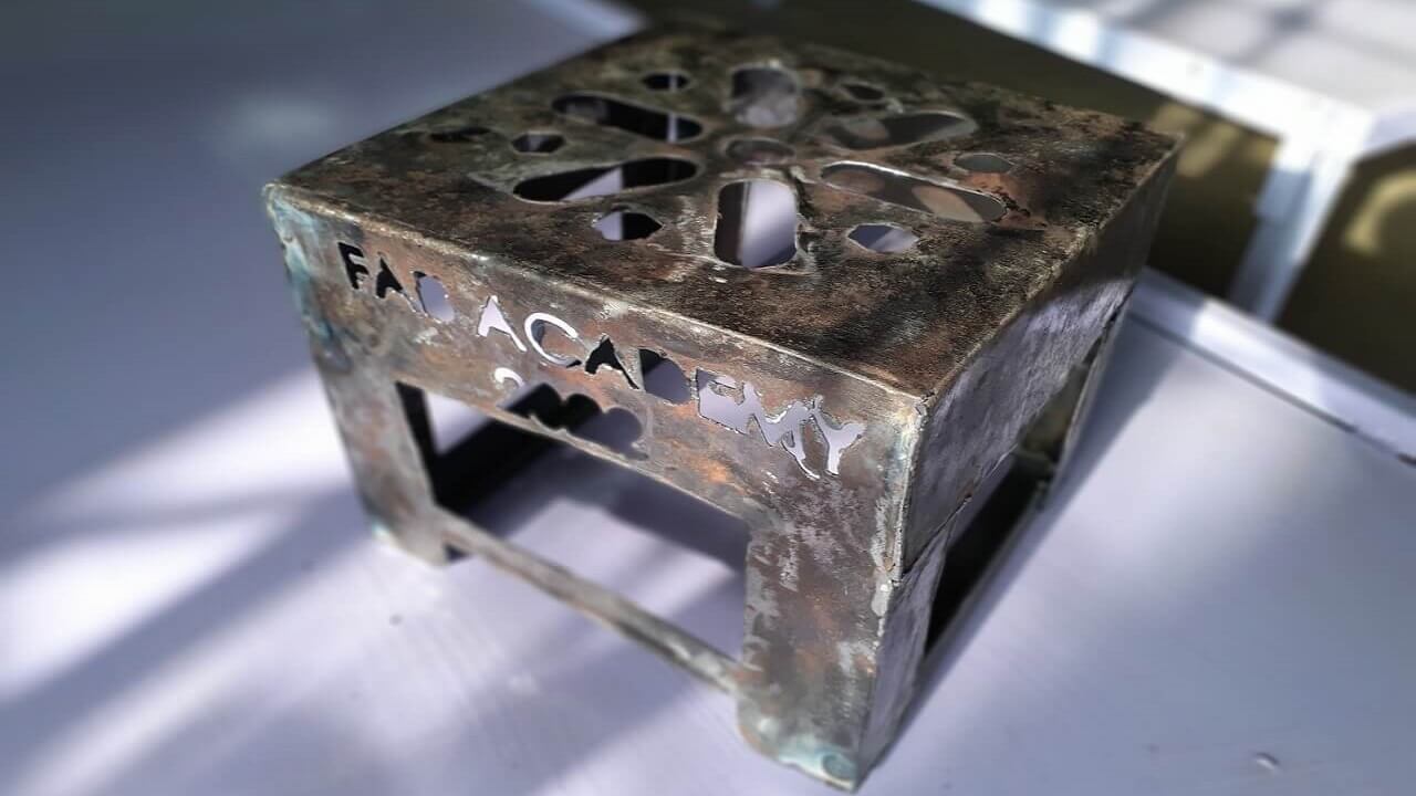
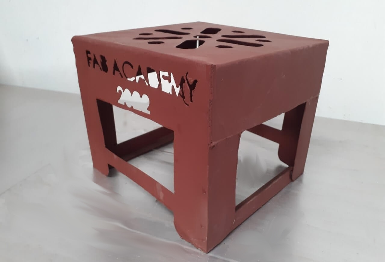
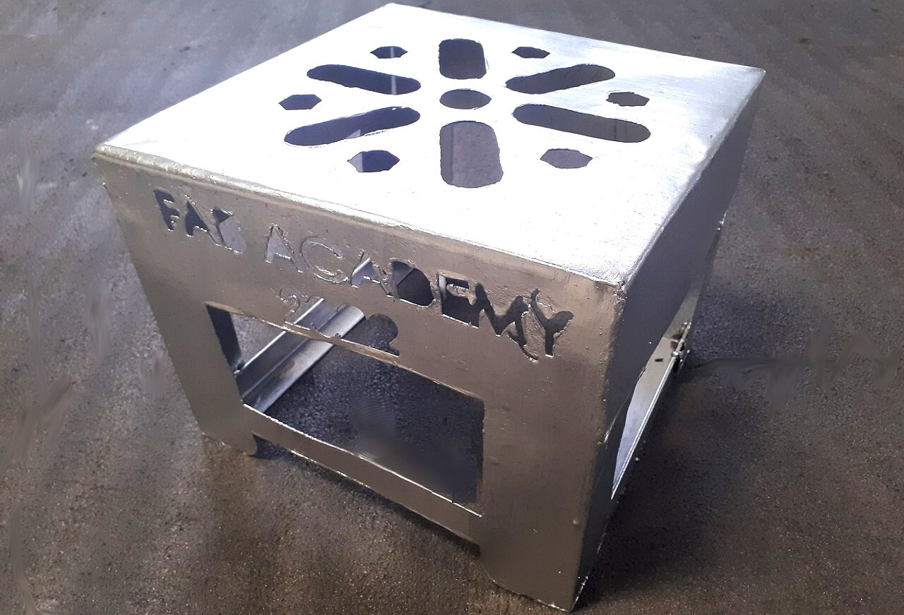
My Hero shots for this week
.png) |
 |
 |
 |
 |
 |
 |
 |
Click here to go back to the top
Individual Assignment
Objectives of Individual Assignment:
- Design and produce something with a digital fabrication process (incorporating computer-aided design and manufacturing) not covered in another assignment, documenting the requirements that your assignment meets, and including everything necessary to reproduce it.
Basics of Plasma cutting
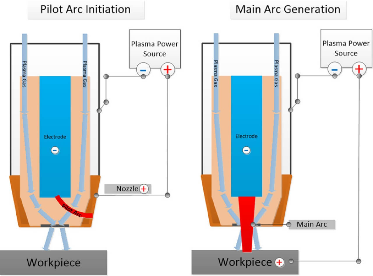
Plasma cutting is a process that cuts through electrically conductive materials by means of an accelerated jet of hot plasma. Typical materials cut with a plasma torch include steel, stainless steel, aluminum, brass and copper, although other conductive metals may be cut as well. Plasma cutting is often used in fabrication shops, automotive repair and restoration, industrial construction, and salvage and scrapping operations. Due to the high speed and precision cuts combined with low cost, plasma cutting sees widespread use from large-scale industrial CNC applications down to small hobbyist shops.
The basic plasma cutting process involves creating an electrical channel of superheated, electrically ionized gas i.e. plasma from the plasma cutter itself, through the workpiece to be cut, thus forming a completed electric circuit back to the plasma cutter through a grounding clamp. This is accomplished by a compressed gas (oxygen, air, inert and others depending on material being cut) which is blown through a focused nozzle at high speed toward the workpiece. An electrical arc is then formed within the gas, between an electrode near or integrated into the gas nozzle and the workpiece itself. The electrical arc ionizes some of the gas, thereby creating an electrically conductive channel of plasma. As electricity from the cutter torch travels down this plasma it delivers sufficient heat to melt through the workpiece. At the same time, much of the high-velocity plasma and compressed gas blow the hot molten metal away, thereby separating, i.e. cutting through, the workpiece.
Credits and Reference: Click here.
What is Plasma?
The three most commonly cited states of matter are solid, liquid, and gas. Plasma, however, is often referred to as the fourth state of matter, and is technically the most commonly occurring state-by volume and mass-as it is found throughout and outside the galaxy (e.g., in the centers of stars and the form of lightning).
Plasma occurs when additional energy is added to a gas, which allows the gas molecules to move faster and collide with greater force. The collisions between molecules enable the molecules to separate into their constituent atoms and these individual atoms to separate from their outer shell electrons, forming ions. As more atoms lose their electrons, the gas reaches a critical point where the number of atoms losing electrons and the number of atoms taking in free electrons achieve balance. At this point, the ionized gas becomes plasma.
 |
Credits and Reference: Click here.
CNC Plasma Cutting Machine:
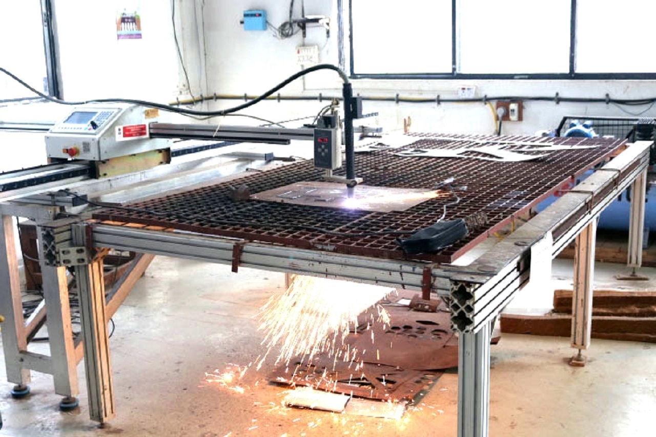 |
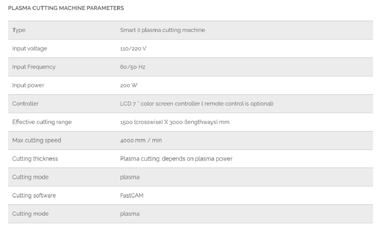 |
CAD Modeling of work stool:
I used solidworks sheet metal tool to design the work stool. Following are the steps I followed to design the CAD model.
.png) |
Go to Base Flange/Tab toolbar to begin drawing a sketch.
.png) |
I chose 300 (width) x 210 (height) mm as dimensions of the stool.
.png) |
Trimmed one side of the rectangle I drew.
.png) |
Go to Base Flange/Tab again.
.png) |
Extruded the flange to 300 mm again as shown below.
.png) |
The table top cross-section is going to be 300 mm x 300 mm.
.png) |
.png) |
Cut extruded part of the side sheet as per these dimensions.
.png) |
.png) |
Go to Edge-flange option to create a flange from the edge selected as shown below.
.png) |
Created a flange at 90 degree from the edge selected as shown below.
.png) |
Selected 'Bend Outside' option to create a flange at 90 degree from the edge selected as shown below.
.png) |
.png) |
Modified the dimensions of this flange as below.
.png) |
.png) |
This flange now looks like this.
.png) |
Created a mirror of this flange taking a reference of the Front plane.
.png) |
Created another mirror of these two flanges now taking a reference of the Right plane.
.png) |
The stool now looks like this.
.png) |
Again go to Edge-flange option to create a flange from the edge selected as shown below.
.png) |
Selected 'Bend Outside' option to create a flange at 90 degree from the edge selected as shown below.
.png) |
Added fillets to all the flanges.
.png) |
Started creating a sketch on the sitting surface of the stool and cut extuded this part.
.png) |
.png) |
Used a circular pattern to create the design pattern as seen below.
.png) |
.png) |
The stool now looks like this.
.png) |
.png) |
Added a three-point arc and a polygon taking a reference of this arc as shown below.
.png) |
.png) |
Cut extruded this sketch.
.png) |
Used a circular pattern to create the design pattern as seen below.
.png) |
.png) |
Go to Unfold option.
.png) |
Select this surface and select 'Collect All Bends' as per the images below.
.png) |
.png) |
The flat part after unfolding looks like this.
.png) |
Added small triangular notches at these corners to identify the bending lines later.
.png) |
.png) |
Go to Fold option as shown below to fold the part again.
.png) |
Select this surface and select 'Collect All Bends' as per the images below.
.png) |
.png) |
Go to Flatten option as shown below to fold the part again.
.png) |
Select this surface to flatten the part.
.png) |
The flattened part looks like this.
.png) |
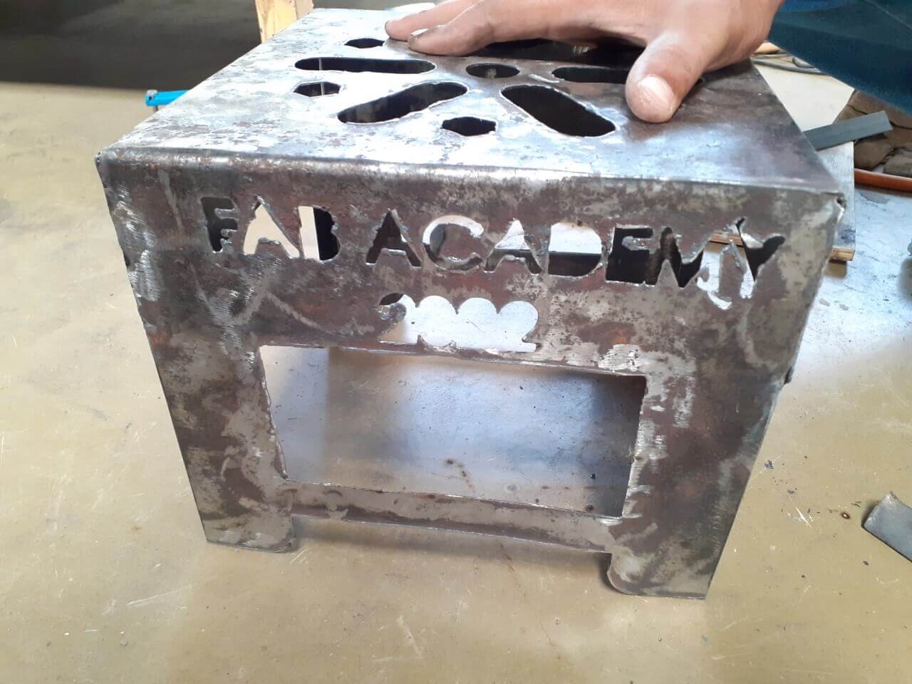
Added some text to the design.
.png) |
|
The flattened part with text looks like this.
.png) |
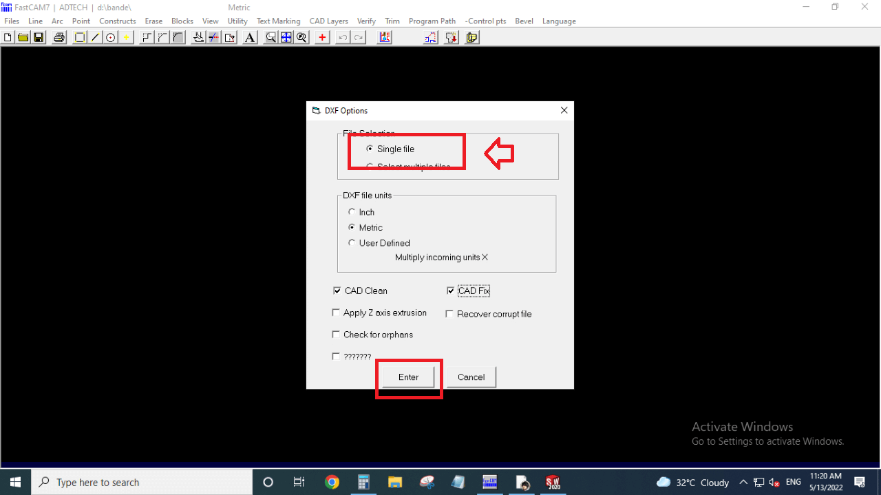
Saved this flattened part as dxf file.
.png) |
.png) |
The dxf fil that I will be feeding to the plasma cutting machine.
.png) |
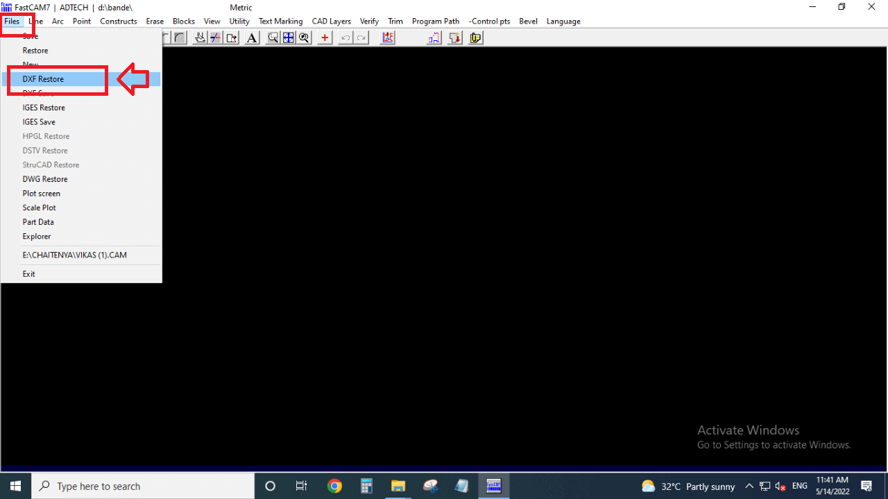
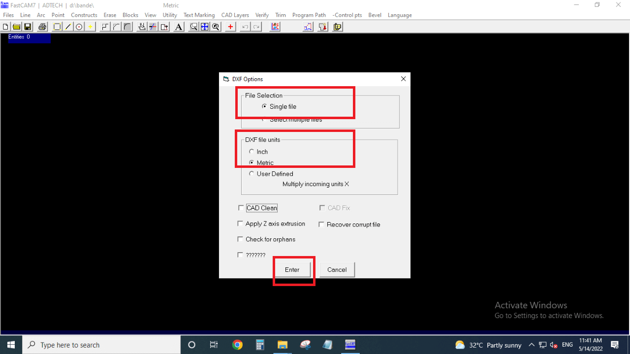
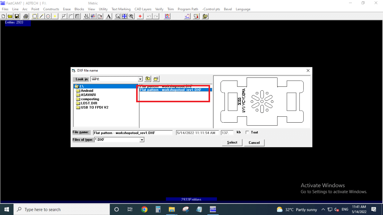
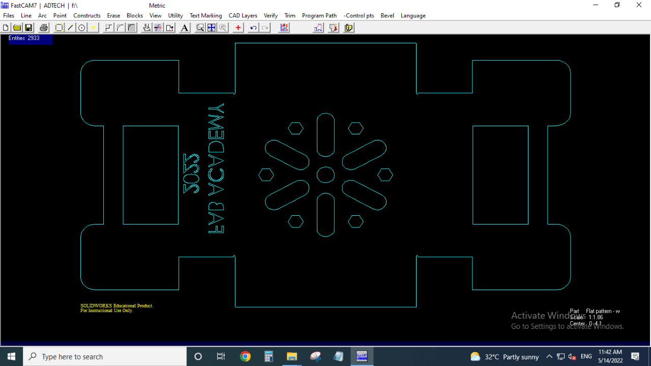
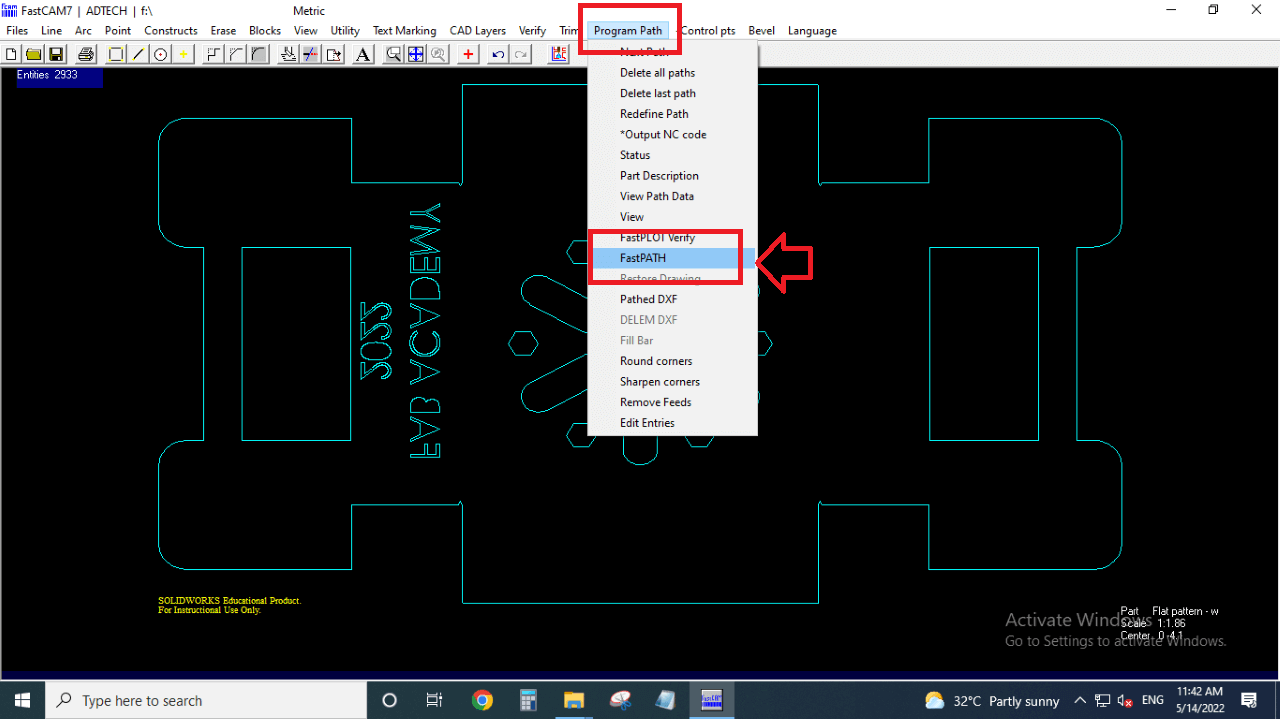
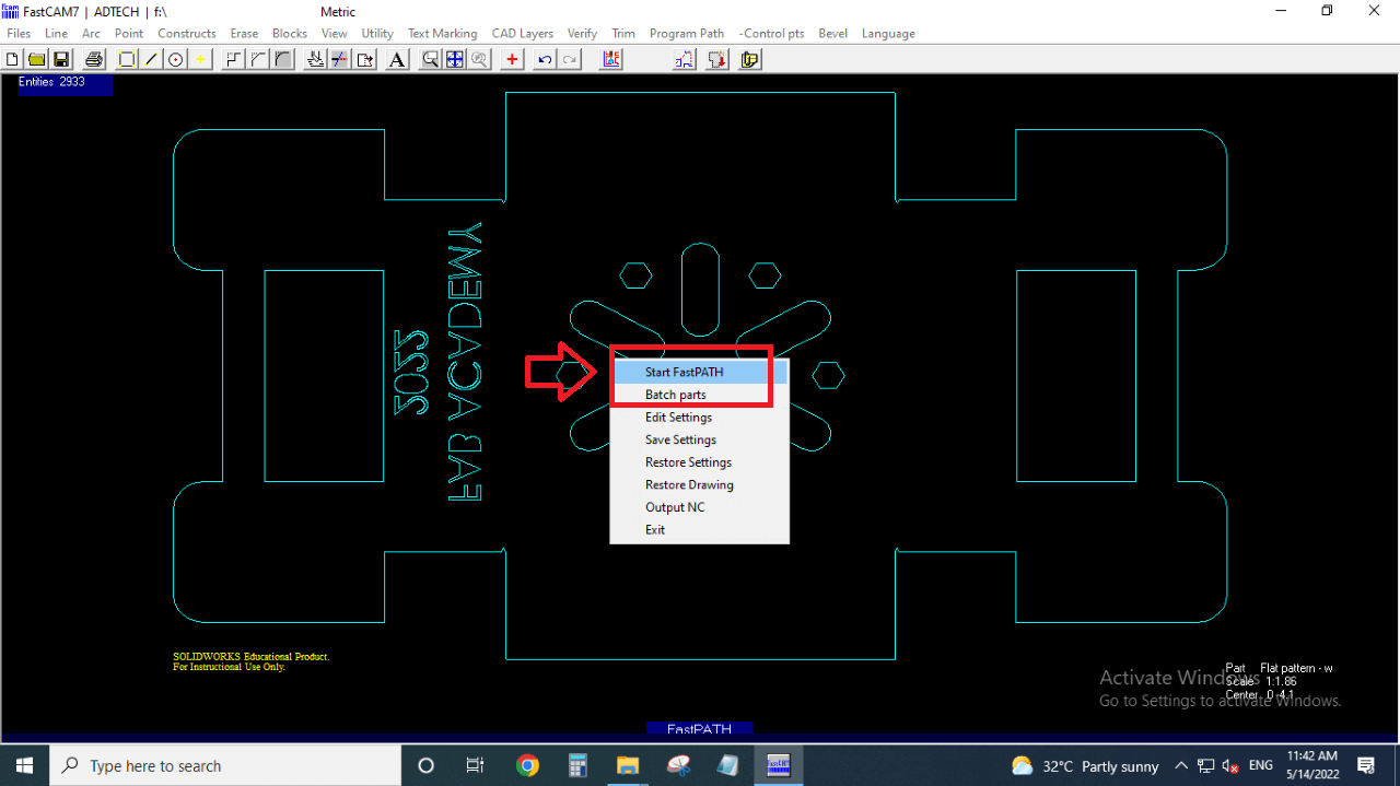
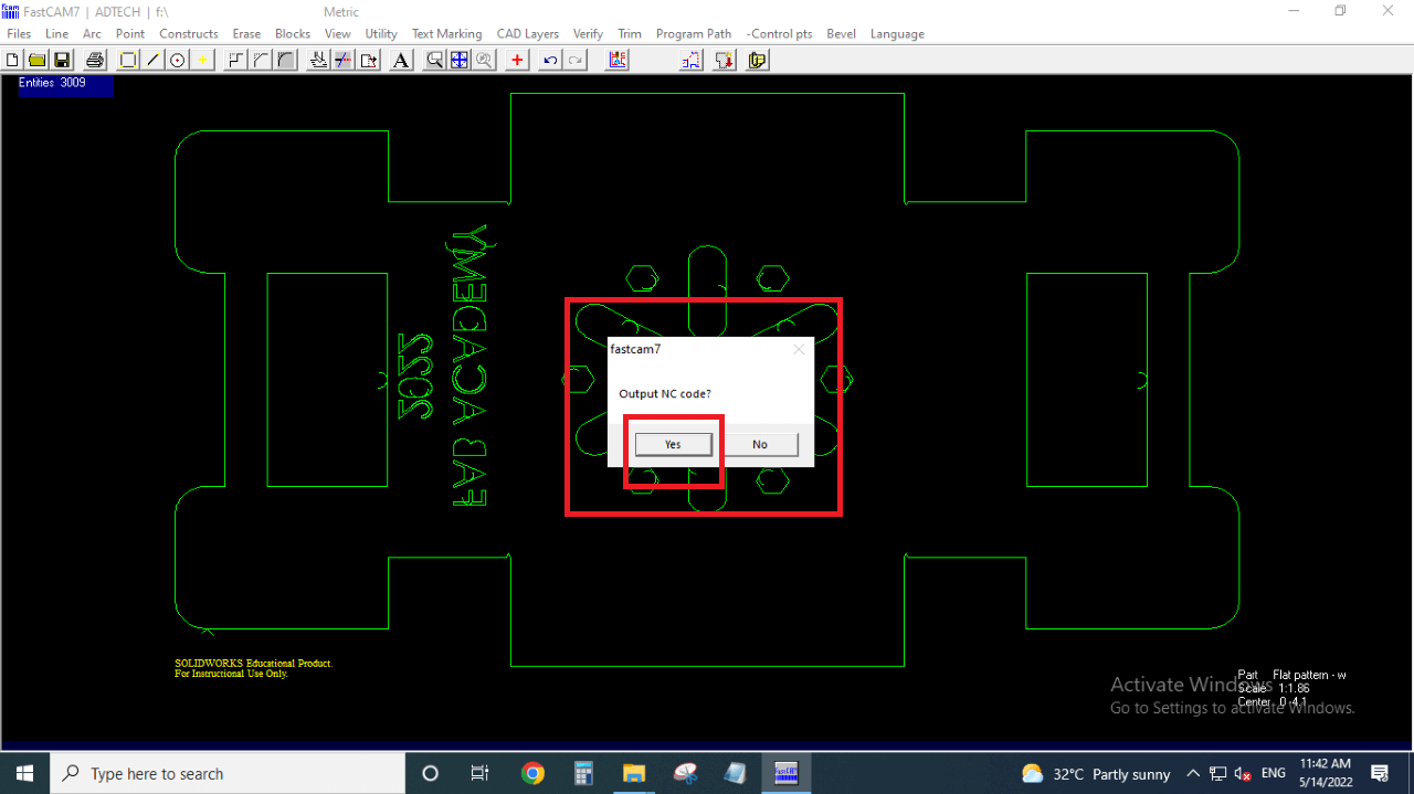
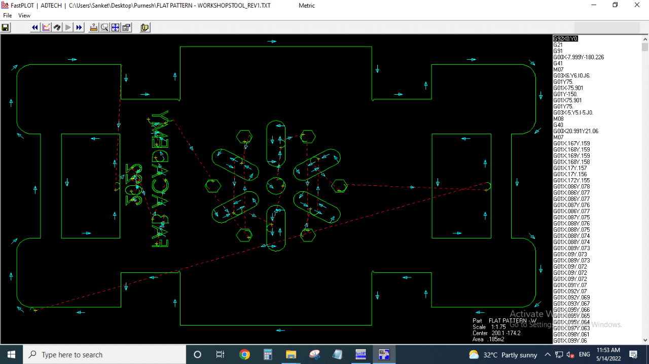
Genereating Toolpath for Plasma-cutting machine:
I used FastCAM software to generate the toolpath as shown in the images below.
 |
 |
 |
 |
 |
 |
 |
 |
 |
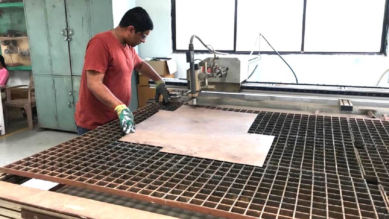
Setting-up Plasma-cutting machine:
 |
|
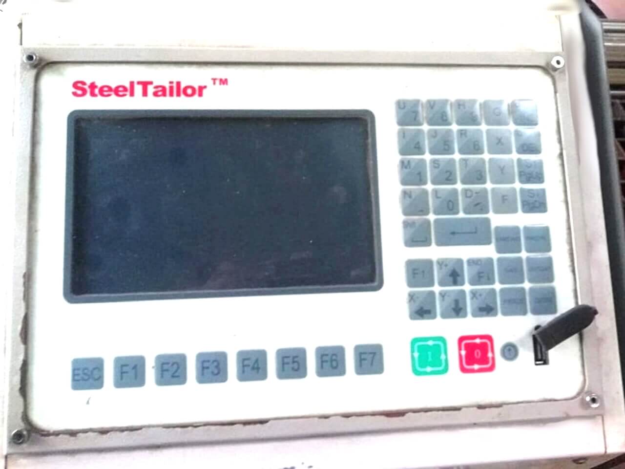
First we need to switch on the supply and Air compressor with control panel. Below is the main control panel display from, where we can give commands to machine.
 |
After switch on the supply and powering machine ON, we need to attched the USB drive to this panel and open the gcode generated earlier.
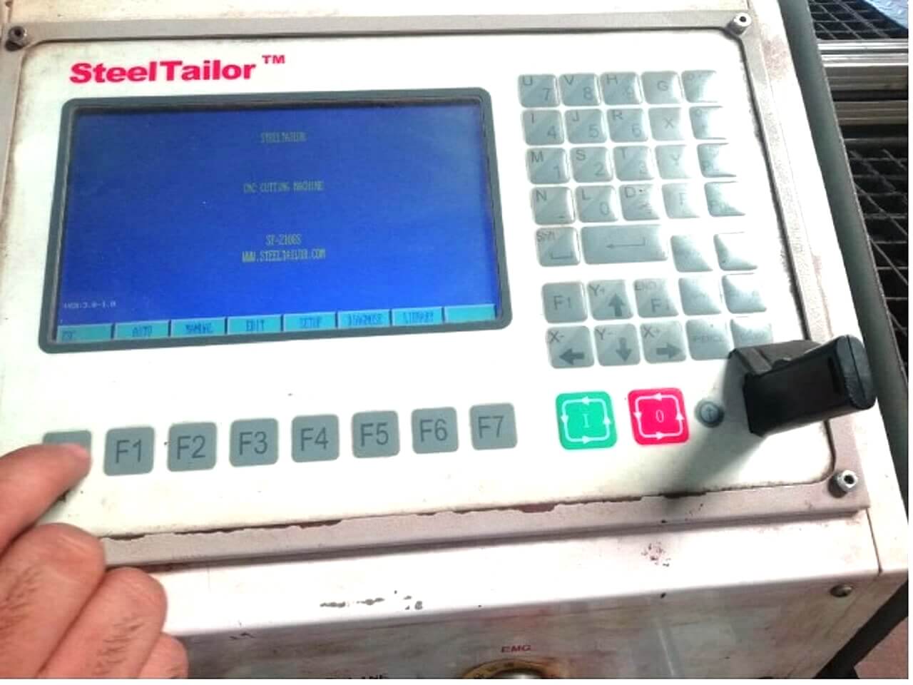 |
Open your file from the USB drive. For that, first load the USB by clicking on F6 button.
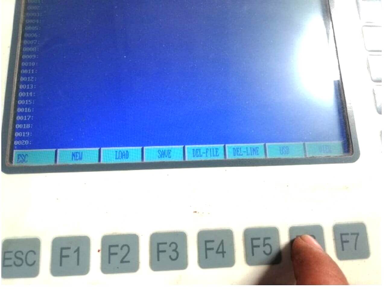 |
Then open your Gcode's txt file by up and down keys on the panel.
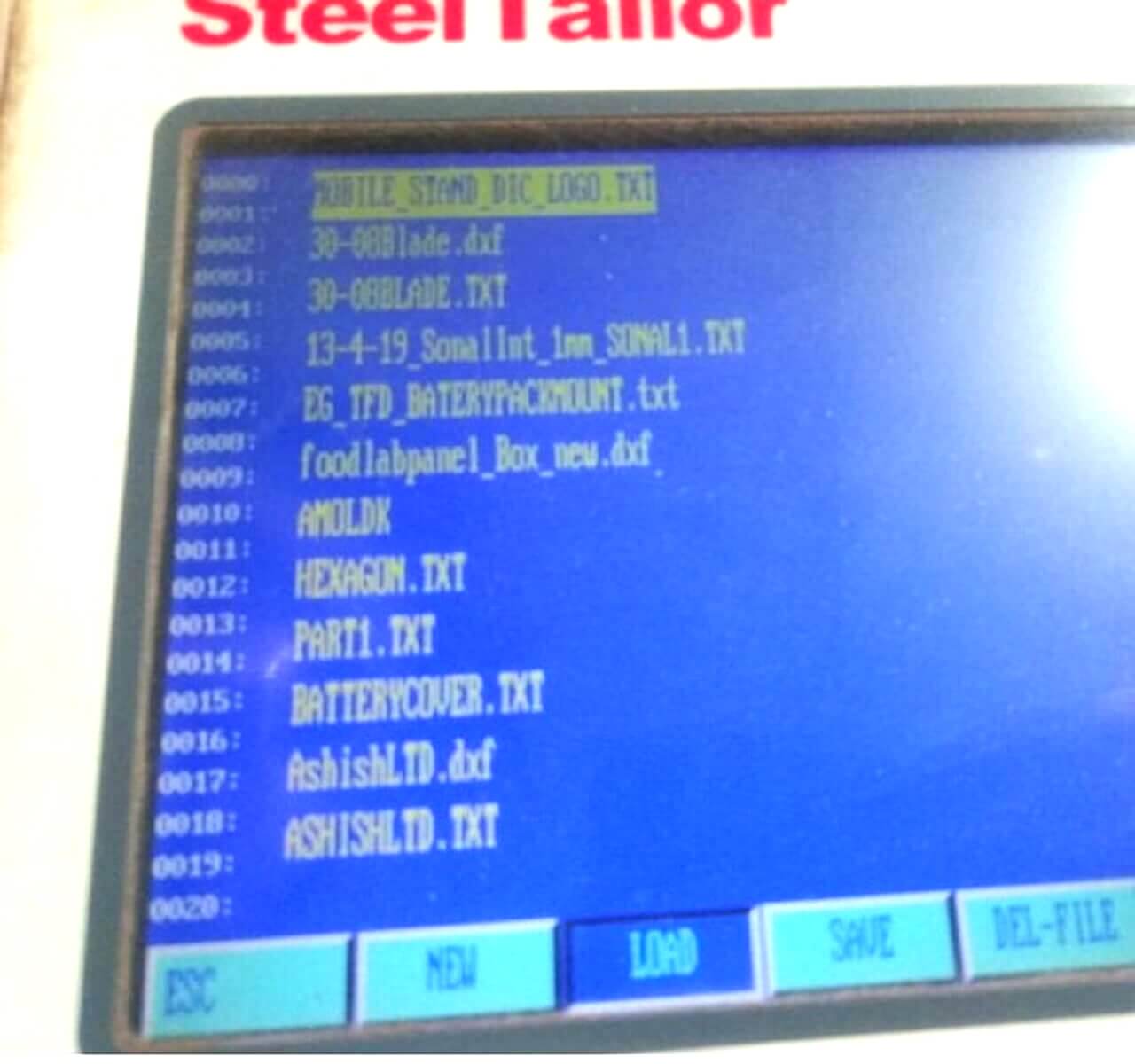 |
Then by clicking on load option G-code will be opened on the screen.
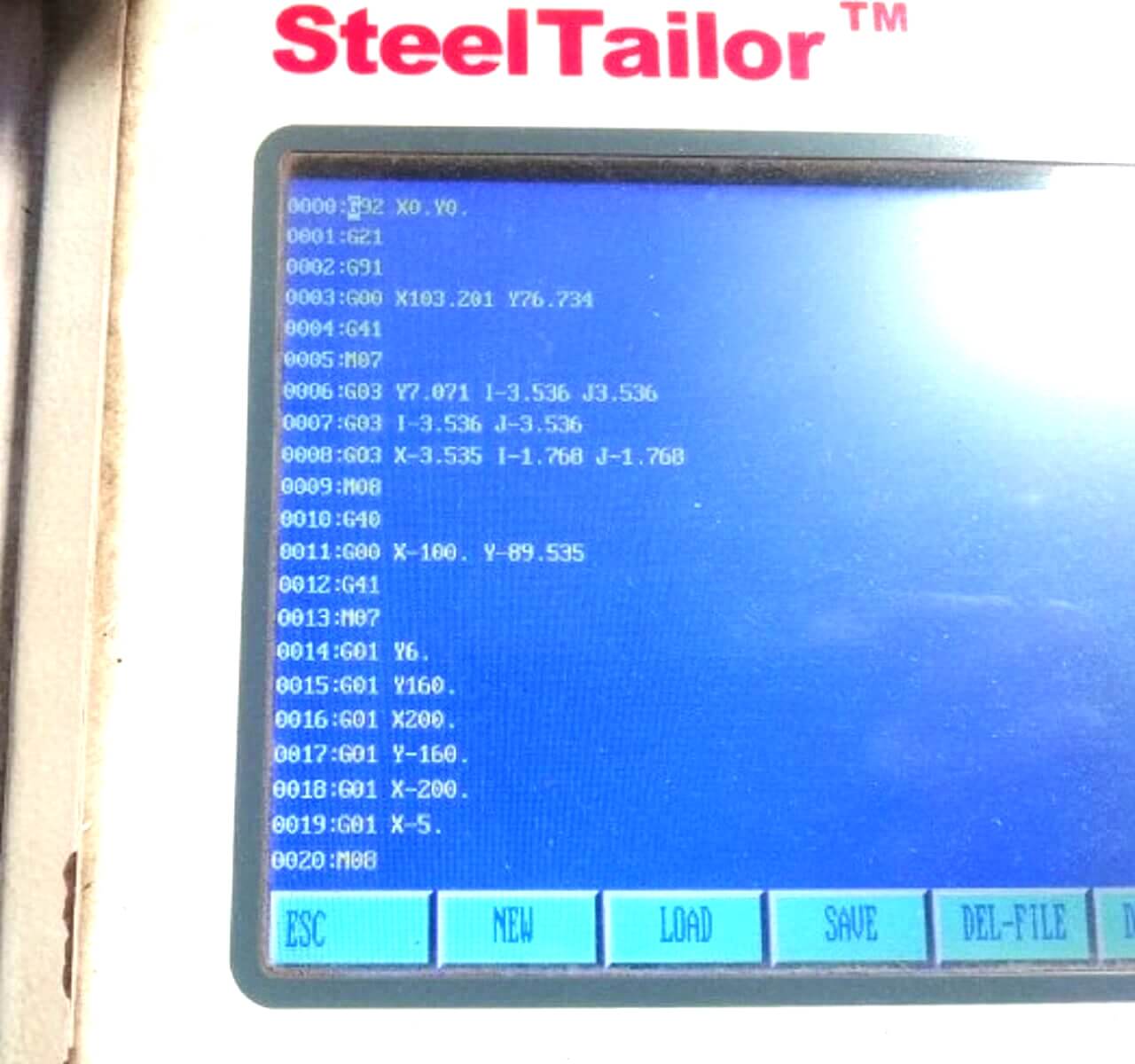 |
Then Press Escape button and your toolpath will be opened on the screen.
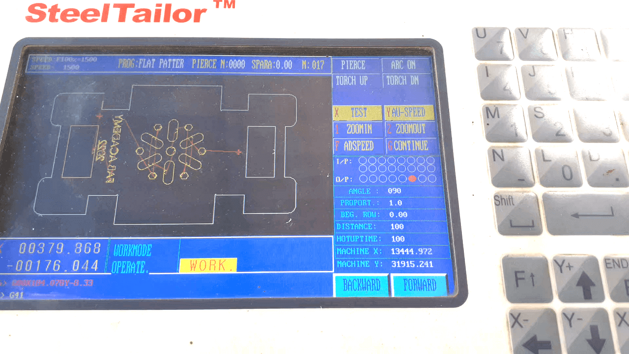 |
Verifying cutting frame for my part:
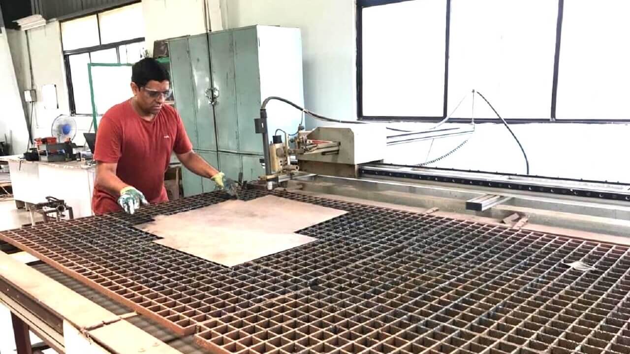
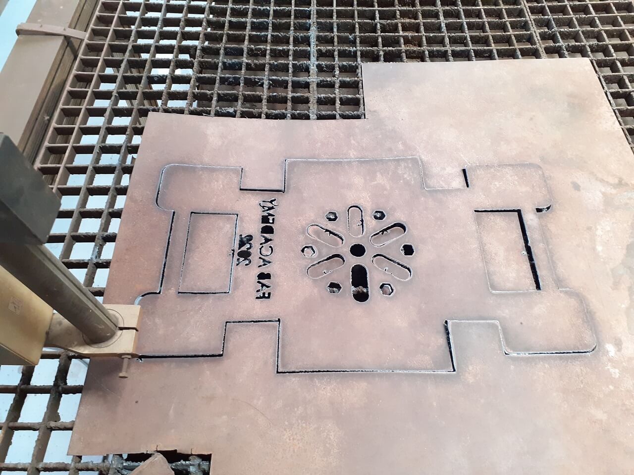
Plasma cutting of the part:
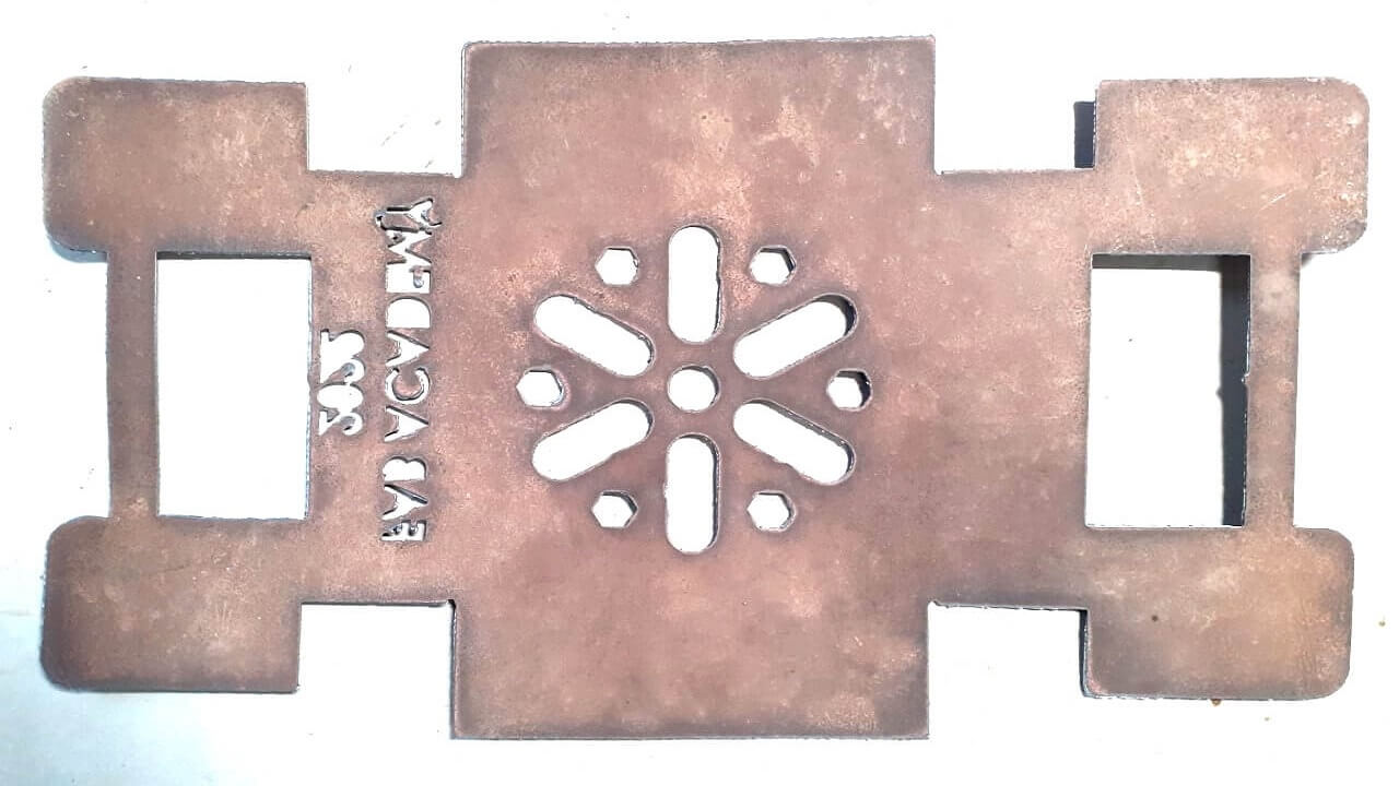
Final plasma cut part.
 |
|
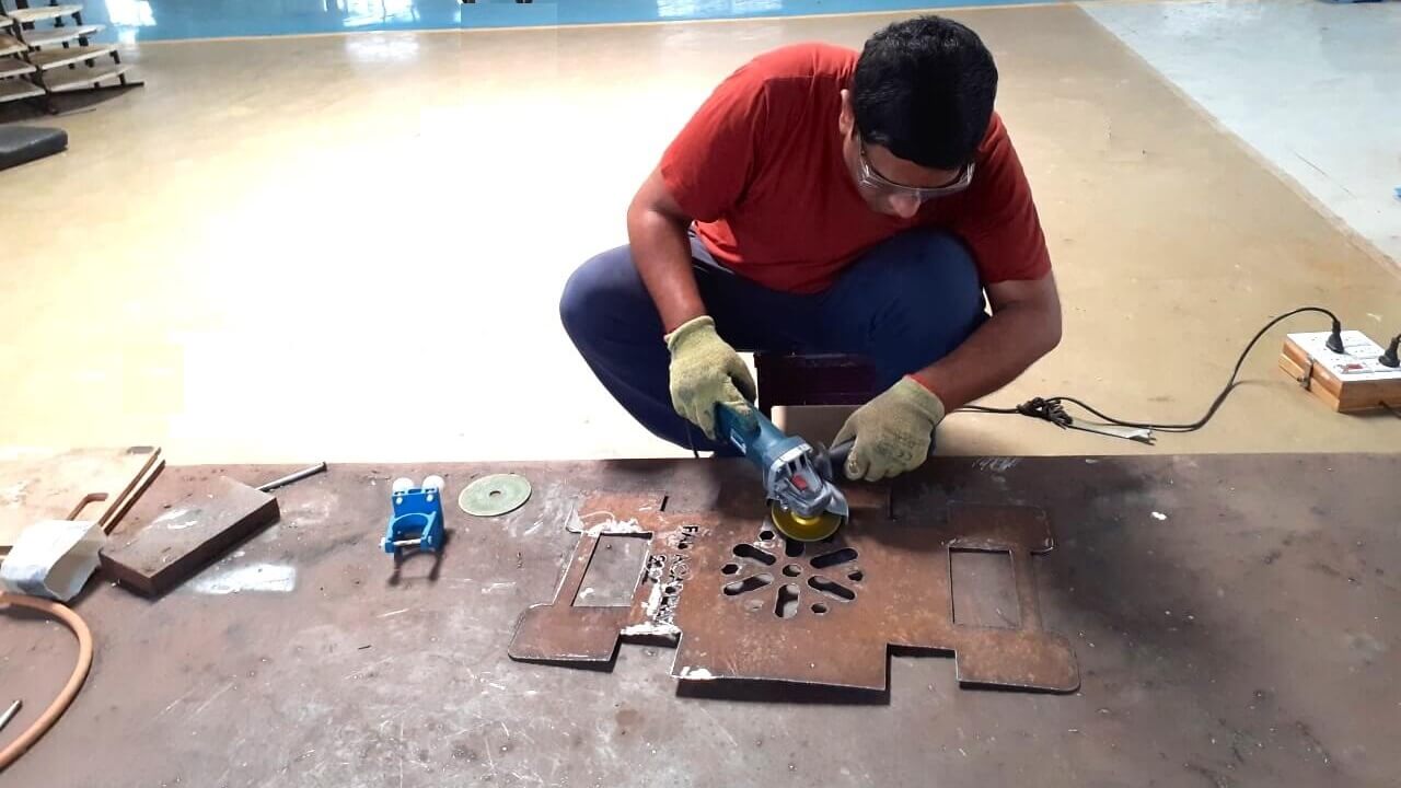
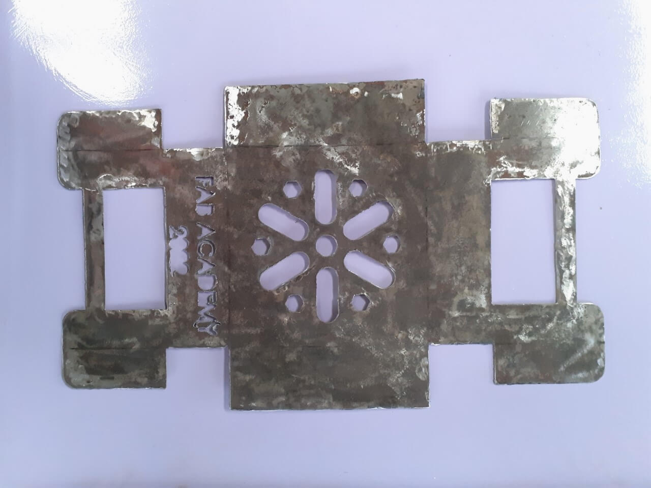
Grinding the cut part.
|
 |
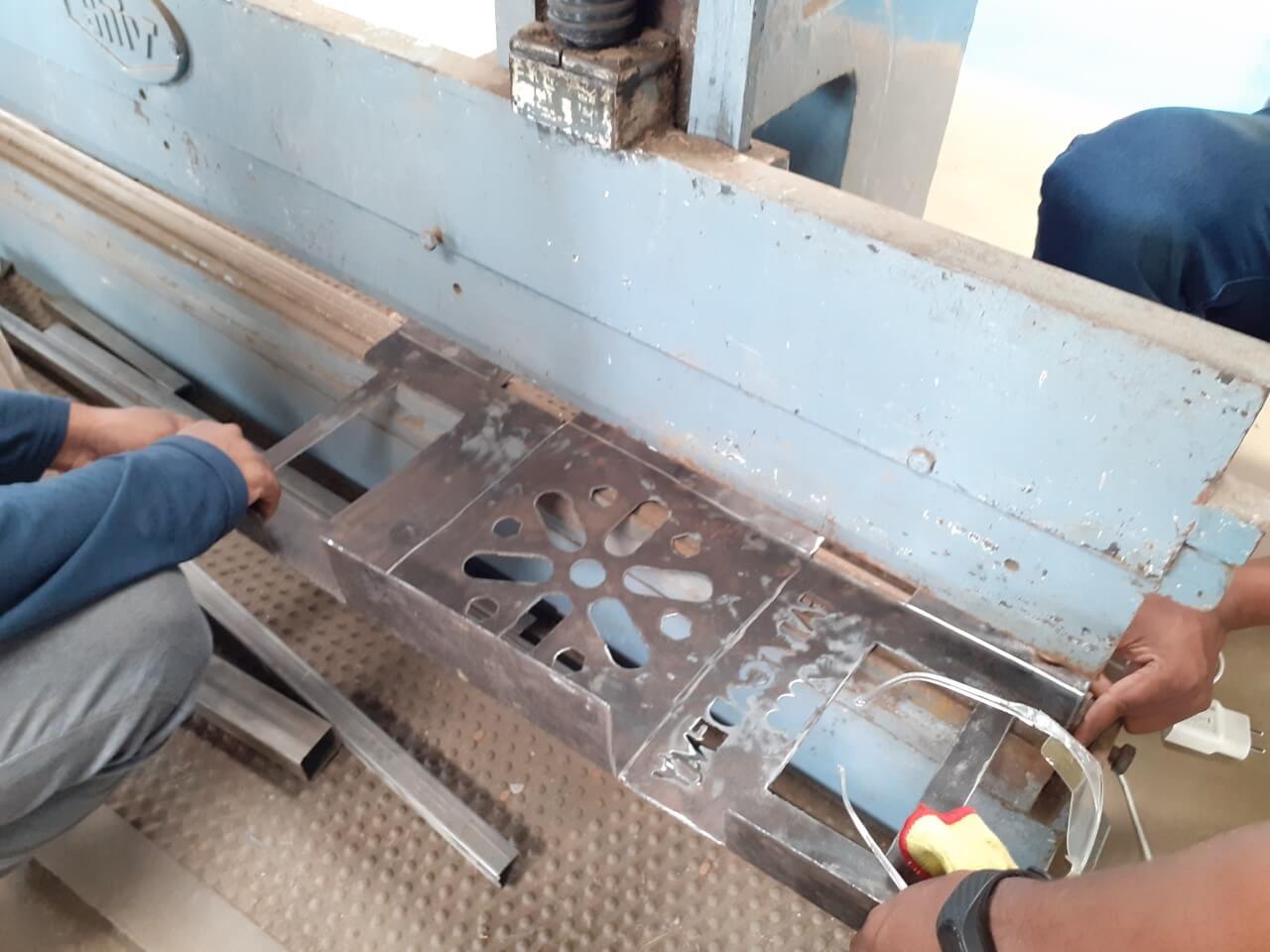
Bending sheet metal part.
 |
 |
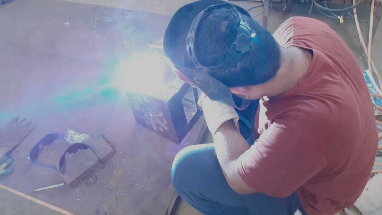
Welding a few joints in the part.
|
|
Painting the part with Red oxide primer paint.
|
Top-coat painting with aluminium silver paint.
|
Click here to go back to the top
Download Original Files
Click here to download all original files. You can download STL file from sketchfab also. See below.
Click here to go back to the top
What went well
- I was able to design my part using sheet metal module in solidworks.
- I was able to work on plasma cutting, bending, welding processes along with digital fabrication processes.
What went wrong
- The bending line at one edge was little offset from the designed line. So, the stool was little tilted. However, I made corrections in to the bending line and the issue was resolved.
- At one joint, during welding, the sheet was little burnt by overheating.
What I would do differently
- I would have tried some other proceess this week.
- I would add plates for stengthening in the design itself as I had to weld a couple angle plates, which were not a part of design.
Learning Outcomes
- I learned how to use sheet metal module in solidworks
- I learned how to use FastCAM software to generate G-code for the plasma cutting machine.
- I learned how to operate the CNC plasma-cutting machine.