This assignment is about documenting what I learned in 2D and 3D computer-aided design, image and video editing, etc. I have documented raster 2D design, vector 2D design and 3D design. I am also documenting what I learned in image resizing and video editing applications and softwares and their importance in documentation of assignments and project. I am also documenting what went well, what went wrong and how I would do things differently in next assignment.
2D Design is the art of digitally creating graphic contents and layouts. It can be sorted mainly into the categories of Pixel-based (Raster) Graphic Design and Vector-based Graphic Design, although very often both techniques are used to create a graphic. Standard 2D design elements include line, shape, color, value, texture. 3D design is the process of using computer-modeling software to create an object within a three-dimensional space. This means that the object itself has three key values assigned to it in order to understand where it exists within the space.
Then, why do designers use 3D design in their work? They are often confronted with unique problems that can be creatively solved, so it helps to have as many tools available in the toolbox as possible. 3D design is one of those tools for designers that brings greater emphasis and visual variety to the elements in their design. This is especially important when considering the human factors associated with UX design because they want to make sure that their digital designs offer a similar experience to the products and systems used in the physical world.
Along with this, I learned the importance of image resizing and video editing applications and softwares and their importance in documentation of assignments and project. While documenting my work throughout my fab academy, I am going to collect many images and videos. They consume a lot of space on drives and cloud specifically. So, it is important to resize, edit them. I need to also learn video making, editing softwares as I need to present my work effectively in shortest possible time.
In raster 2D design, the images are made of individual building blocks such as pixels, or tiny dots that use color and tone to produce the image. Pixels have one or more numbers associated with them. These numbers define the location, size, or color of the pixels. They appear like little squares on graph paper when the image is zoomed in or enlarged. These images are created by digital cameras, by scanning images into a computer or with raster-based software.
Once the image is created at a certain dimension, one may not be able to use this image at a larger size without losing the quality of the image. JPEGs, GIFs and PNGs are common raster image types. Almost all of the photos found on the web and in print catalogs are raster images. Raster images are typically acceptable for digital publication but may not work well in printed projects. Often these files are saved as low resolution and are not suitable for print reproduction.
GIMP, MyPaint are some of the open source softwares, while Photoshop is a commercial software used for raster 2D design. I used Adeobe Photoshop 2022 for practice.
Photoshop: 2D Raster Design Software
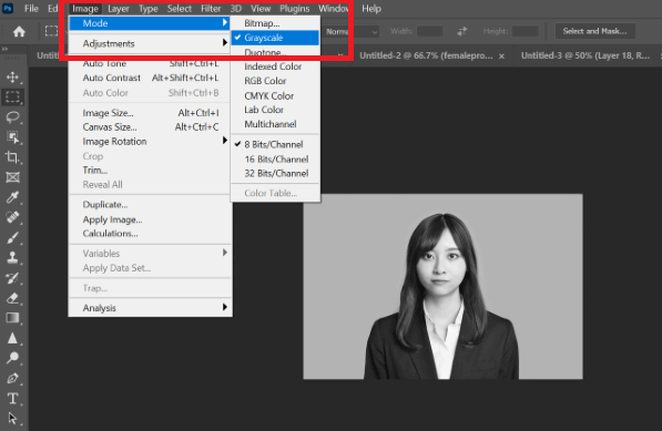
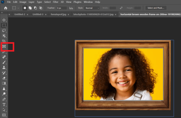
Adobe Photoshop is used to edit raster images. Editing is done to change the brightness, color saturation, tone, sharpness, applying any filters, etc. One can also use photoshop to crop images, remove background, appply frame around images, etc. I used photoshop to perform various operations to edit images.
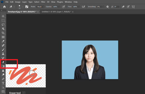
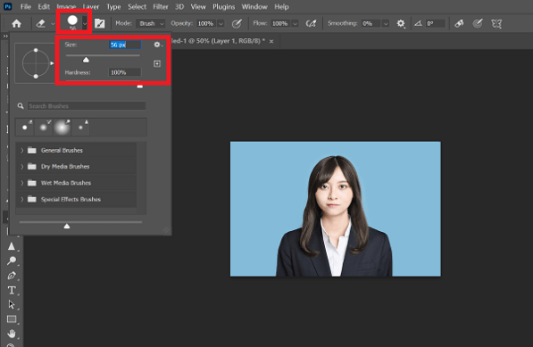
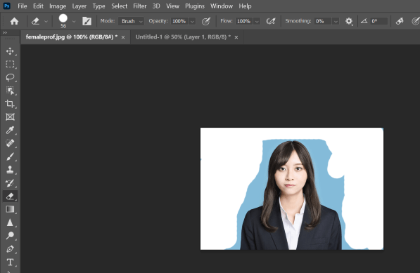
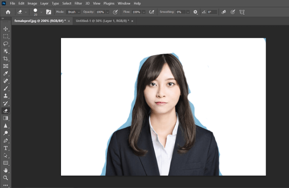
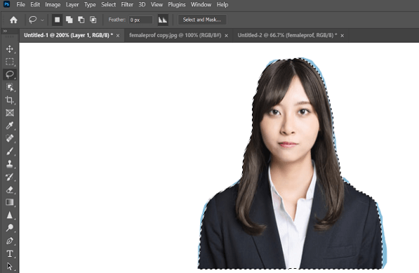
1. First, I used eraser tool to remove the background of the image. One can select the size and hardness of the eraser depending on how precisely they want to remove the background.
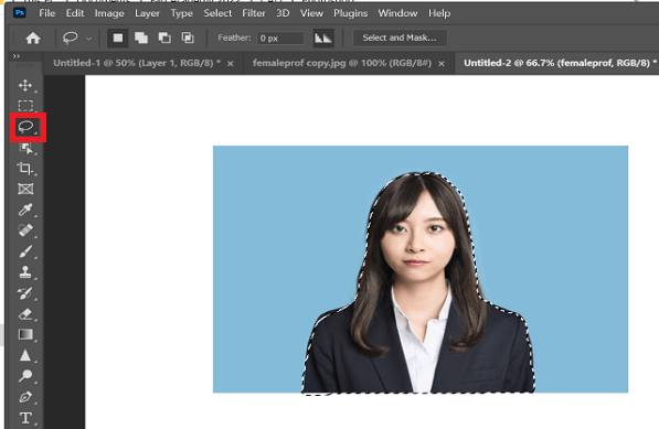
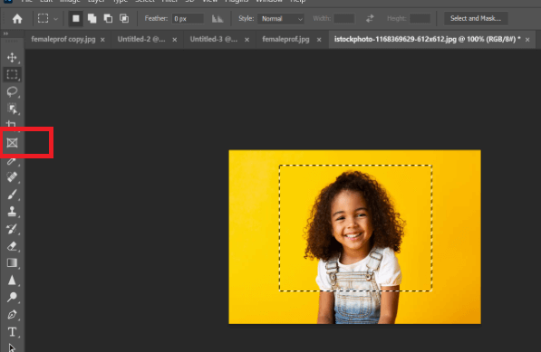
2. Then, I used lasso tool to select a specific portion of the image to copy that portion to some other image. Once lasso tool is selected and applied, we can not release the mouse until the desired portion is selected for copying .
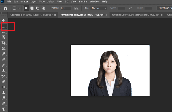
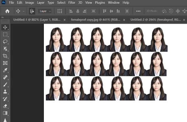
3. Then, I used rectangular marquee tool to select a specific portion of the earlier image to copy that portion of the image as multiple images in new file. One can print multiple copies of the same image once e.g. passport size photo printing in the photo studio.
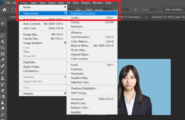
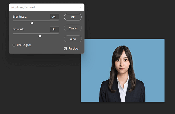
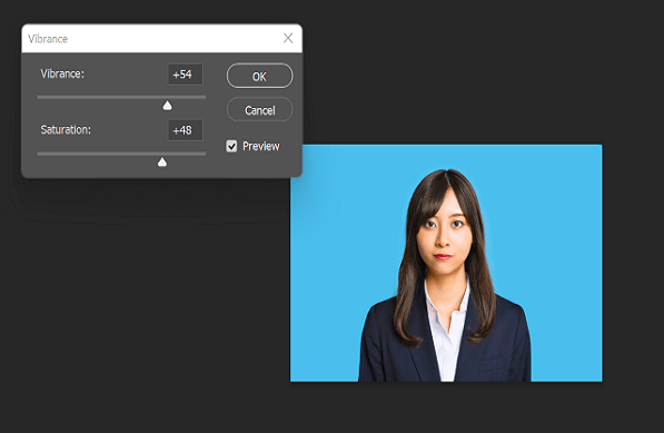
4. I then tried image adjustment menu to change the brightness and contrast of the image as well as changing the vibrance, color saturation of the image.
5. Lastly, I used frame tool to create placeholder frames for images using some photoframe images like the one I used below.
In this type of 2D design, Vector graphics, as a form of computer graphics, is the set of mechanisms for creating visual images directly from geometric shapes defined on a Cartesian plane, such as points, lines, curves, and polygons. Points are connected by lines and curves known as paths that are created with mathematical formulas to form polygons and other shapes. You may be able to identify a vector image by looking at its edges. Text is one of the most common types of vector image.
A vector image will always appear smooth no matter how large you make it or how close you zoom in. No matter how much you increase a font size, for example, its look never changes. The most common problem with using vector images is compatibility. Vector images are often saved as native files from the program used to create the image (such as Coreldraw, Adobe Illustrator), which may not be available to you to open the file. As designers, we prefer this file type when we are creating invitation cards, signage, logos, business cards and more.
INKSCAPE, Sketchpad are some of the open source softwares, while Illustrator and Coreldraw are commercial softwares used for vector 2D design. I used INKSCAPE for practice.
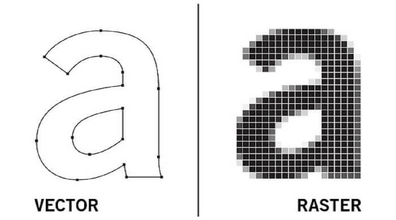
Difference between Raster and Vector Images
I found following image showing the difference between a raster and vector images.
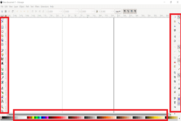
INKSCAPE: 2D Vector Design Software
Inkscape is used to create and edit vector designs and drawings. One can create many vector elements like lines, curves, circles, polygons and use them to create different vector designs for brochure, visiting card, logo, etc. We can import images into it and trace bitmap to create an vector image. Vector designs and drawings are used for laser cutting.
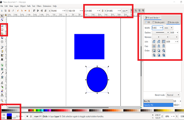
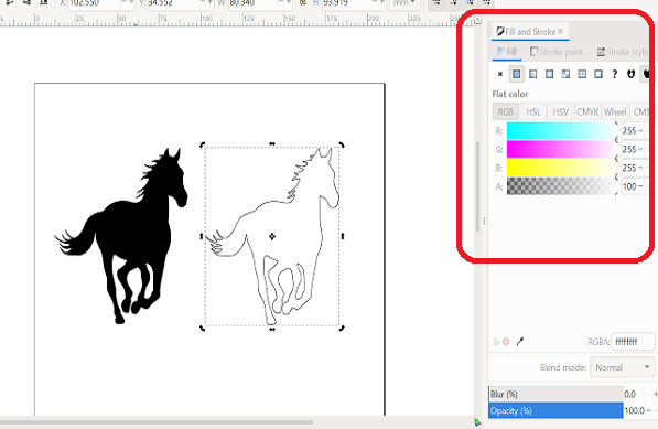
1. First, I explored menu bar and various tools available in Inkscape UI. On left hand side, there are all drawing tools like selection, polygons, spirals, bezier curves, free-hand sketch, etc. On left there are editing tools like cut, copy, paste, apply stroke, import and export, etc. On top of the page, we can change the size of the object drawn and in the bottom, there is color pallete to fill in the color and also apply strokes to objects.
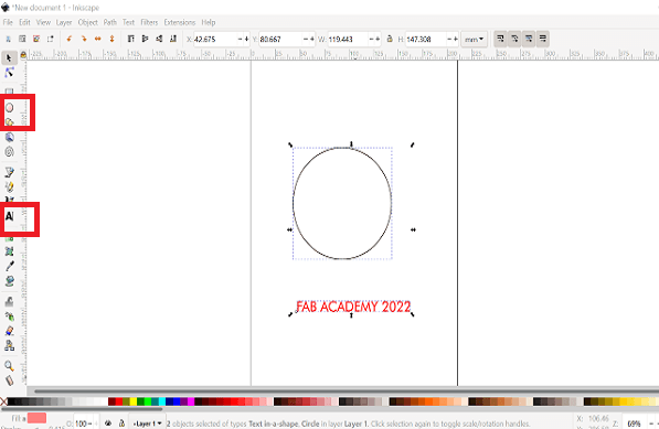
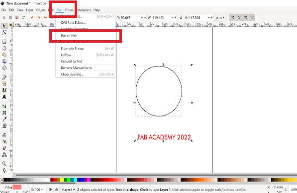
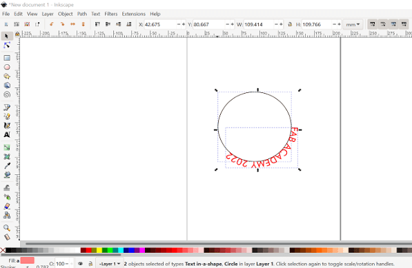
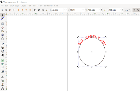
2. Next, I learned- Text: Put on path tool to write the text along a curved path. It is used to design logos. One can create a curved path like circle, add a text and then selecting both of them together, they can use tool- Text:Put on path to move that text along the curved path.
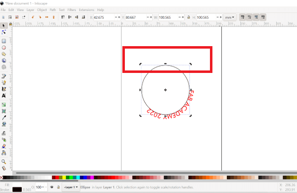
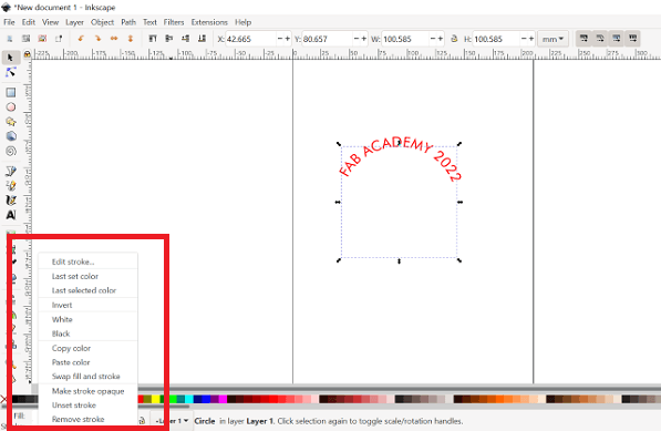
We can click on the image edge to change the side arrows to rotate the circle. Upon rotating the circle, the text will now appear on the top. We can select the apply strokes tool to change the color of the edge of the circle to white. We can not delete the circle as it will delete the reference path for the text.
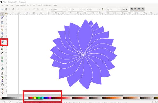
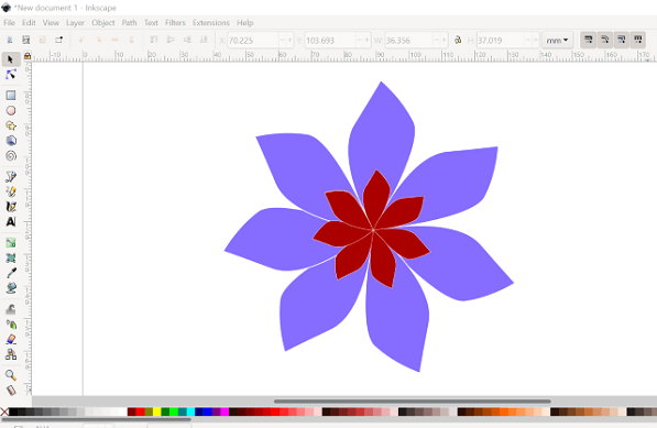
3. I also learned to use bezier curve tool to draw some objects with curved edged and straight lines. Upon editing the object with color and edges- here petal in my example, I clicked rotating arrows and pressed space bar together to create a repetitive pattern. I created a flower like design. I used Ctrl G command to group the objects together. I then copied this grouped objects, change its size and gave it a different color. Lastly, placed these two flowers together to create a beautiful design.
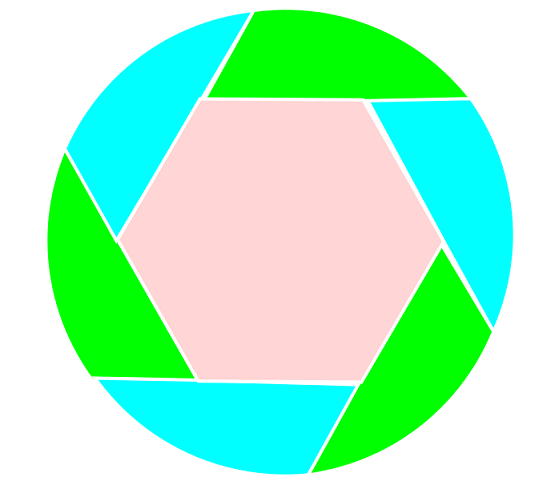
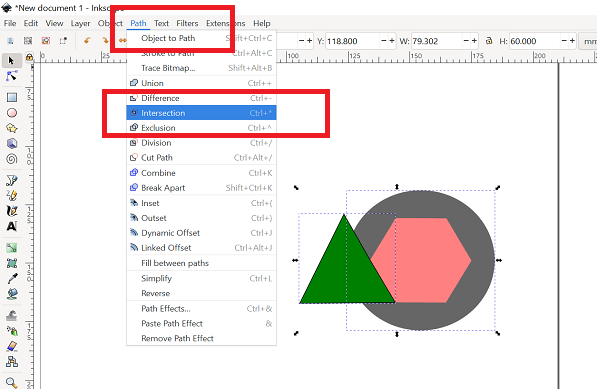
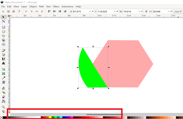
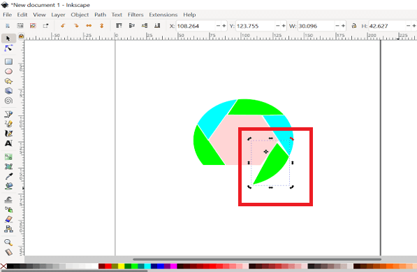
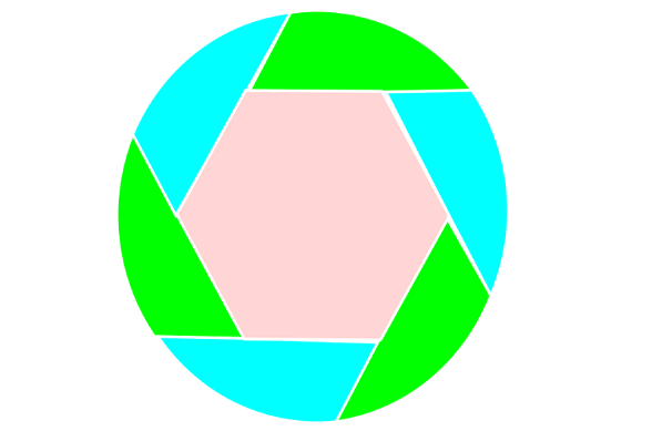
4. Next, I designed a logo using the boolean operation- Path: Intersection. I drew two different objects- a hexagon and triangle. Used intersection command under Path tool to create a desired shape. Then I changed the color of that new shape. I copied these shaped multiple times, rotated and placed them along the edges of the hexagon to create a logo. I gave same color to alternate shapes like a logo.
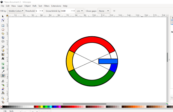
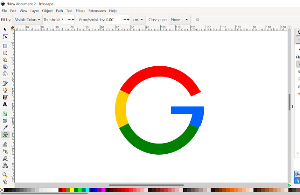
After that, I used- Fill bounded area tool to give color to bounded area in between line to create Google logo. I used boolean operation to merge different objects.
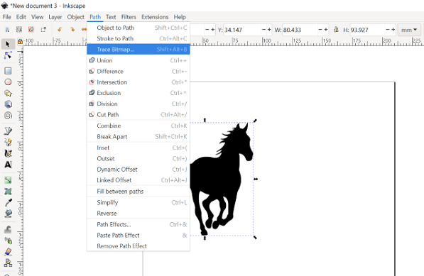
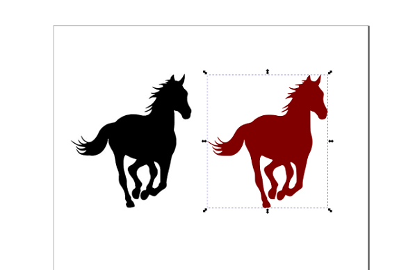
Last thing I tried was to import an external bitmap image and performed the trace bitmap operation through Path command. This way, we can create a vector image from a bitmap image without drawing the outline as a new drawing. We can then use tools like fill and strokes to edit the traced object. This tool and method is useful in tracing images as a vector drawing for laser cutting and engraving..
3D modeling is the digital representation of any object or surface using 3D modeling software. In the most basic case, three-dimensional model can be created from simple shapes like cubes, rectangles, and triangles. These shapes are then modified into complex, high-polygon designs.
3D modeling makes it easier for ideas to be communicated, it is used to create an interactive design of an object or surface that represents a real-life design. Depending on the application, it is also possible to test the structural feasibility of a design. For example, a part of a physical object can be created quickly, its physical properties analyzed, and then the models are updated as needed.
Whether offline or in-browser, 3D modeling software allows designers and companies to model products and present them, internally or to clients, before the final product is created. Not surprisingly, 3D modeling can be both time- and cost-efficient.
Basics of 3D Modeling
At a fundamental level, one needs to know the building blocks of 3D modeling. Here are the most important terms:
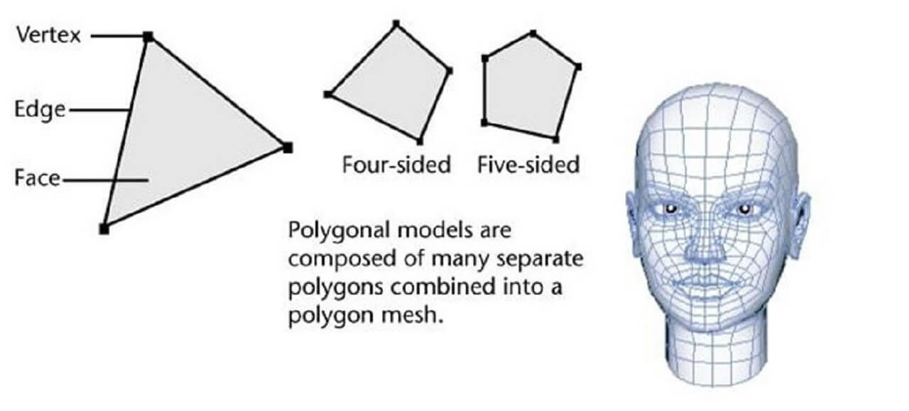
Vertex: A single point and the smallest component of a 3D model. Edge: A straight line that connect two vertices. Edges help define the shape of a 3D model. Polygon: Any shape that is formed by connecting straight lines. There are several types of polygons (equilateral, equiangular, regular, irregular, cyclic, convex, concave) depending on the number of sides and the extent of the angles. Face: The most basic part of a polygon mesh. It helps fill up the space between the edges. When flat surfaces in a model are covered, they form a face. Mesh: A collection of polygons that are connected in their faces, edges, and vertices. A 3D object consists of one or more 3D meshes.
Every 3D modeling program works in a 3D environment, which is visualized via computers using: Vector: A geometric object with length and width. It is normally represented using an arrow. Plane: A two-dimensional surface that extends afar.
Three Main Types of 3D Modeling
Solid: Unsurprisingly, this 3D modeling technique is used to produce solid shapes. It aims to ensure that all 3D objects are geometrically correct. Compared to the other two type, solid modeling is more complex, as it requires simulating the exterior and interior of the model.
Solid modeling is helpful in the creation, animation, design, and visualization of functional models. The designer is able to see how the design looks and works from the very beginning.
Surface: Surface modeling is a mathematical method for displaying or presenting solid 3D objects. It focuses on the external aspect of a 3D model, allowing you to view the 3D model from different angles at solid surfaces.
Surface modeling is easier to work with than solid modeling, though it is more complex than wireframe. It is mostly used in architectural illustrations and animations in video games.
Wireframe: Wireframe modeling is based on generating a 3D model by bending a wire and following the edges of an object. These 3D models consist entirely of points, arcs, circles, curves, and lines.
A wireframe object is not recognized as solid . Instead, the boundary of the object is recorded as points and their connections. When compared to surface and solid modeling, wireframe is the least complex method of representing 3D objects. Typically, triangles are the basic elements in wireframe modeling. The more triangles, the higher the realism.
Techniques used in 3D Modeling
Boolean operations: It includes union, difference, and intersection, which are used to create complex designs when combined with the basic shapes. Surface operations form an airtight cavity through trimming and knitting that resembles a solid object. Pick and place: It creates the desired modification by working directly on the edges, vertices, and surfaces. A good example of this is chamfering, shelling, and drafting. Parametric modeling: It controls the geometric shape of a model by manipulating the parameters. If everything is defined properly, major changes can be made according to minor aspects.
TINKERCAD, Onshape are web based 3D modeling applications, which have free access for education. SketchUp too has a web based 3D modeling application, which is free to access to anyone. It also has paid desktop software. FreeCAD and OpenSCAD are some of the open source desktop softwares, while Solidworks, Autodesk Fusion 360, CATIA and Creo Parametric are commercial softwares used for 3D design. I used FreeCAD and Solidworks software for practice.
FreeCAD: 3D Design Software
FreeCAD is a general-purpose parametric 3D computer-aided design (CAD) modeler and a building information modeling (BIM) software with finite element method (FEM) support. It is intended for mechanical engineering product design but also expands to a wider range of uses around engineering, such as architecture or electrical engineering. FreeCAD is free and open-source, under the LGPL-2.0-or-later license, and available for Linux, macOS, and Windows operating systems. Users can extend the functionality of the software using the Python programming language.
FreeCAD features tools similar to CATIA, Creo, SolidWorks, Solid Edge, NX, Inventor, Revit, and therefore also falls into the category of building information modeling (BIM), mechanical computer-aided design (MCAD), PLM, CAx and CAE. It is intended to be a feature-based parametric modeler with a modular software architecture, which makes it easy to provide additional functionality without modifying the core system. Click here to read more.
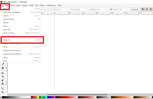
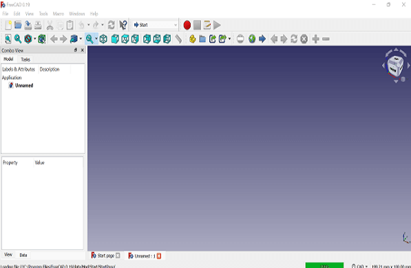
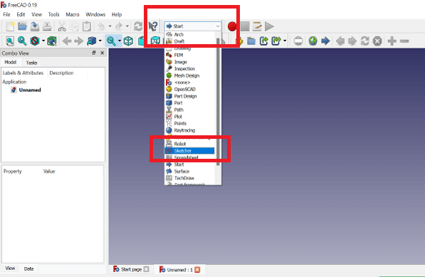
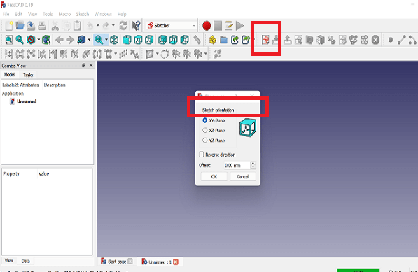
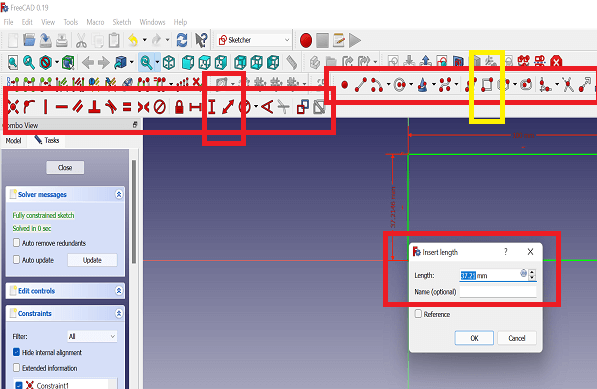
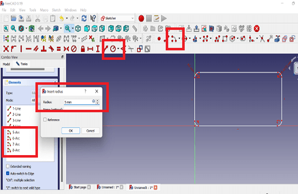
First, to draw a sketch, one has to click on- Start: Sketcher option on the toolbar on the top as shown in the picture. Upon selecting Sketcher option, it asks to select one of the three planes to draw a sketch. Once the plane is selected, we can use the drawing and constraints toolbar on the top to draw objects like line, rectangle, circle, etc., as highlighted in the fourth image below. I drew a rectangle and using the dimension constraints below, gave desired dimensions to the rectangle as shown.
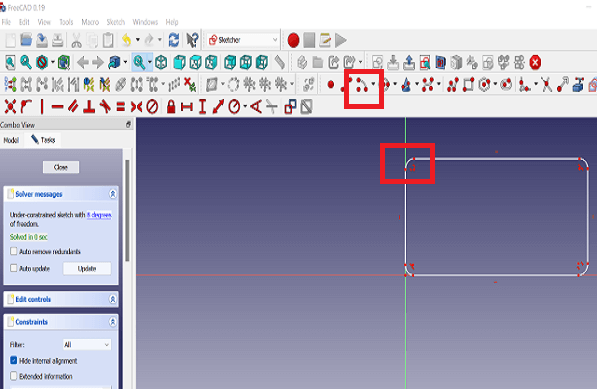
I added arcs on all four corners of the rectangle using Create arc tool on the top and used Fix the radius of an arc constraint to give equal radius to all the four arcs as shown below.
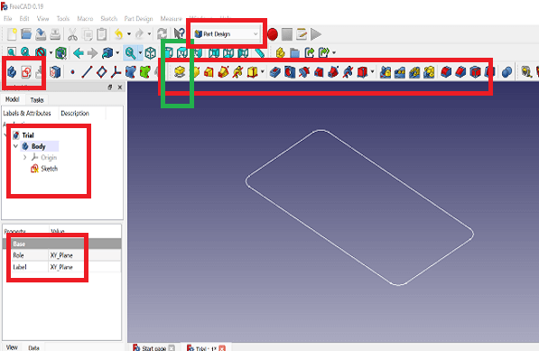
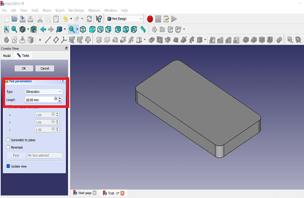
I extruded this rectangle by selecting the Part Design module on the top as shown in the image below. The sketch needs to have a body for performing operations like, extrude, cut, sweep, etc. There is add body button on the left as shown. I selected the XY plane (same plane that I used to draw a rectangle) to create a body for the sketch. I added depth for the extrusion to create a cuboid.
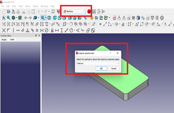
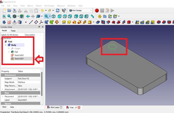
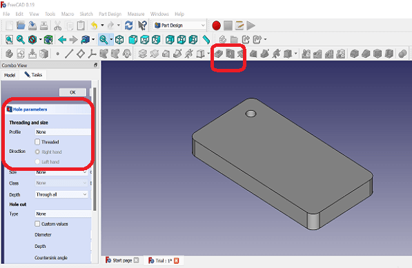
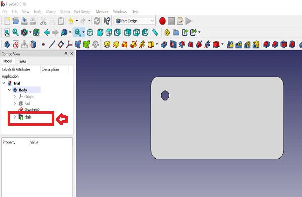
Next, I made a through hole on the cuboid. To do that, I again needed to switch to the sketcher mode as shown in the image. Selected the XY plane and drew a circle, which comes under the same body as highlighted. Using command- Create Hole with selected sketch and using- Through all for depth, a through hole has been created as shown in below images.
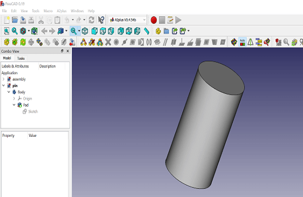
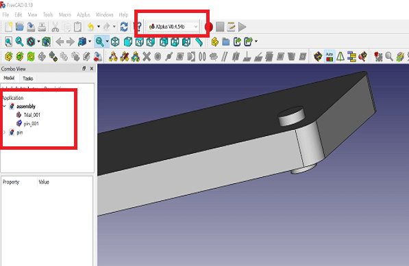
Lastly I tried using Assembly tool A2plus V0.4.54b to assemble a pin in to the through hole that was previously created in to the cuboid as shown in the images below.
Solidworks: 3D Design Software
SolidWorks is a solid modeling computer-aided design (CAD) and computer-aided engineering (CAE) computer program published by Dassault Systemes, that runs primarily on Microsoft Windows. While it is possible to run SolidWorks on an Intel-based Mac with Windows installed, the applications developer recommends against this. SolidWorks does not support macOS.
SolidWorks is a solid modeler, and utilizes a parametric feature-based approach which was initially developed by PTC (Creo/Pro-Engineer) to create models and assemblies. SolidWorks files (previous to version 2015) use the Microsoft Structured Storage file format. This means that there are various files embedded within each SLDDRW (drawing files), SLDPRT (part files), SLDASM (assembly files) file, including preview bitmaps and metadata sub-files. Various third-party tools (see COM Structured Storage) can be used to extract these sub-files, although the sub-files in many cases use proprietary binary file formats. Click here to read more.
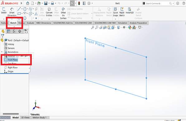
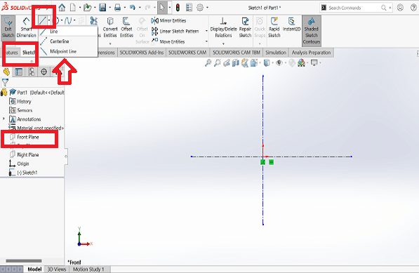
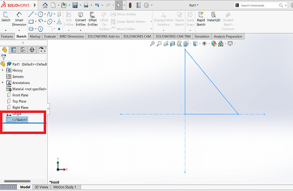
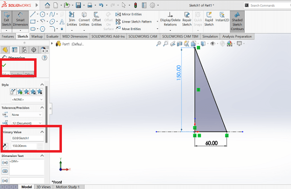
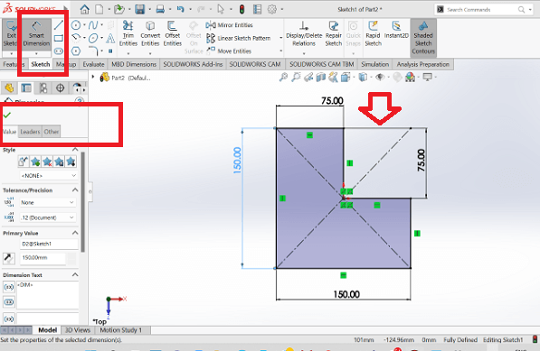
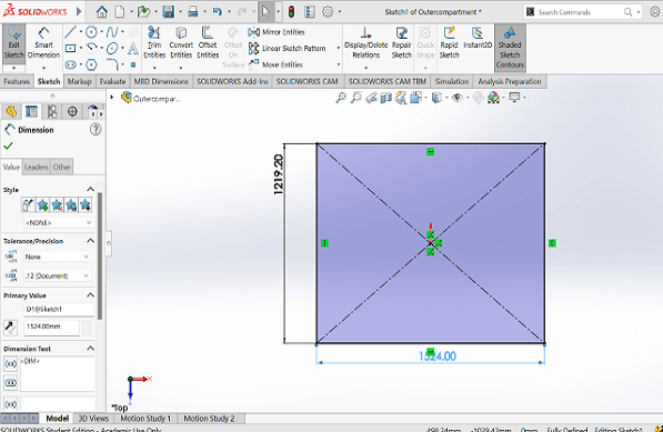
First, to draw a sketch, one has to open Sketch option on the toolbar on the top as shown in the picture. Upon selecting Sketch option, select one of the three planes to draw a sketch. Once the plane is selected, we can use the drawing toolbar on the top to draw objects like line, rectangle, circle, curves, etc., as highlighted in the image below. I drew a triangle and using the Smart dimension tool, gave desired dimensions to the triangle as shown.
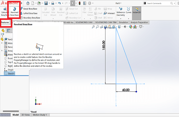
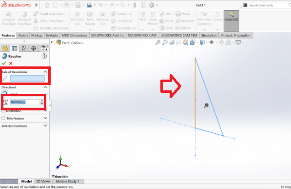
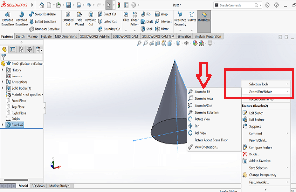
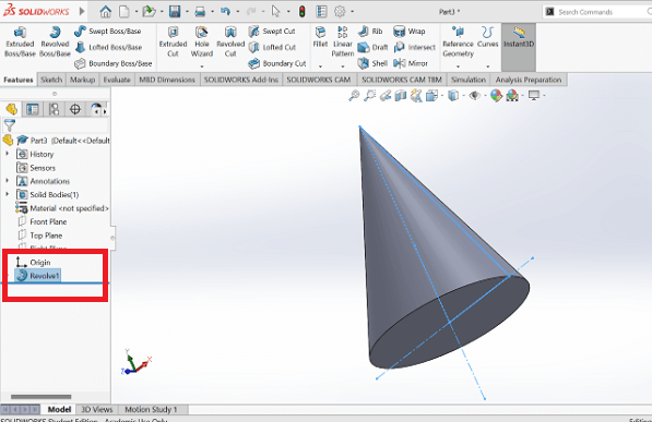
I then used Feature menu near the sketch menu to create a 3D object from the sketch drawn as shown below. I used Revolved Boss/Base command to create a cone from the triangle. I selected the axis around, which the triangle will be rotated and defined the angle of rotation as well. Once the cone was created, I right clicked on the screen to select one of the Pan, Zoom, Rorate, Roll views.
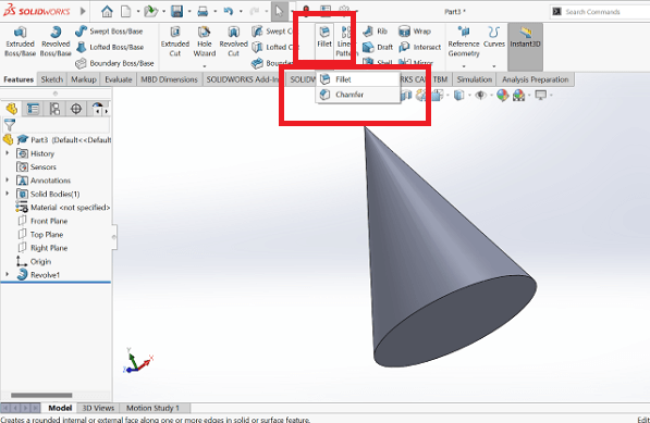
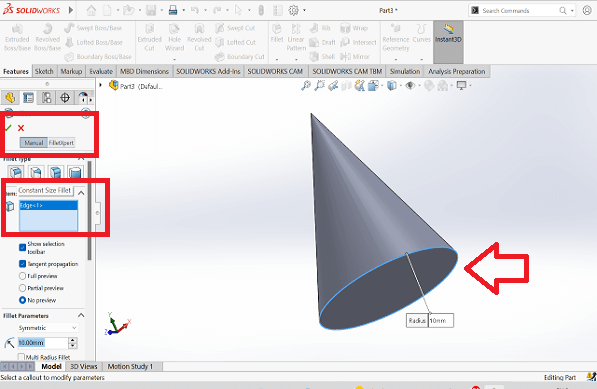
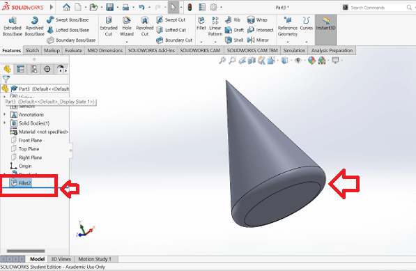
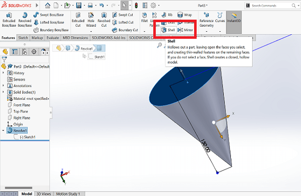
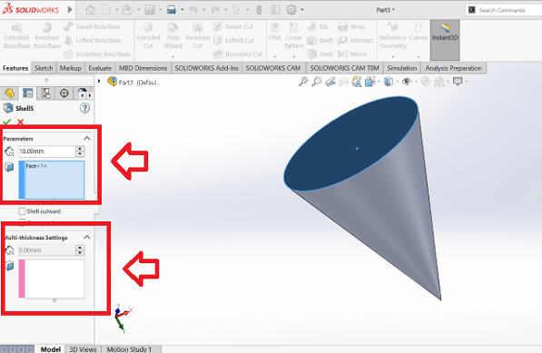
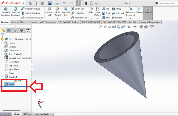
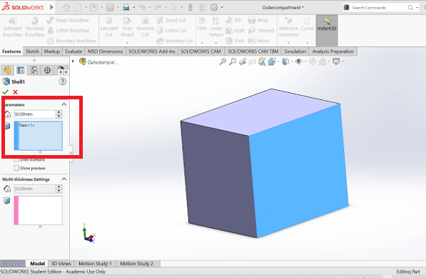
I applied fillet command on the top as shown in the image below. I selected the edge on which I desired to create a fillet and added radius of the fillet. I also used shell command on the top for cut extrude the inner part of the cone. I first selected the face and defined specifications like depth and thickness of wall of shelled cone The shell feature now appears in to the model tree diagram of the left side of the UI
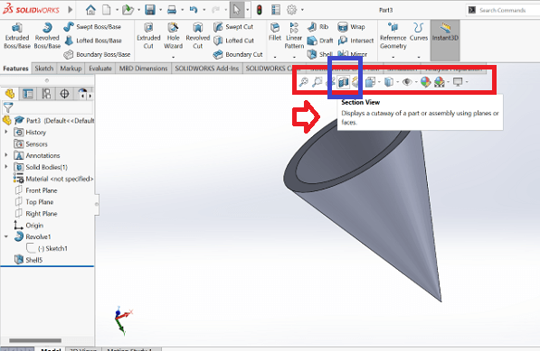
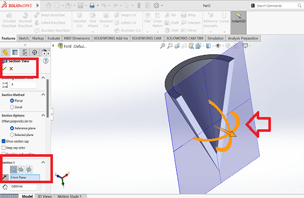
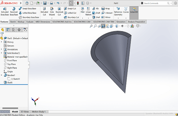
Next, I used section view tool on the graphics screen to see the cut sectional view of the 3D object. I can use the arrows seen on screen to apply the depth at, which I want to see the sectional view as shown in the image. The cut sectional view of the cone looks like the one in third image below.
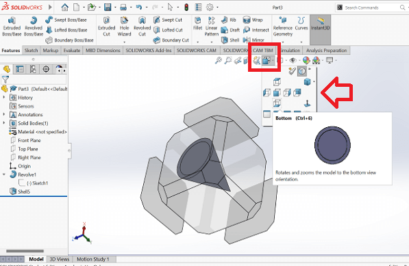
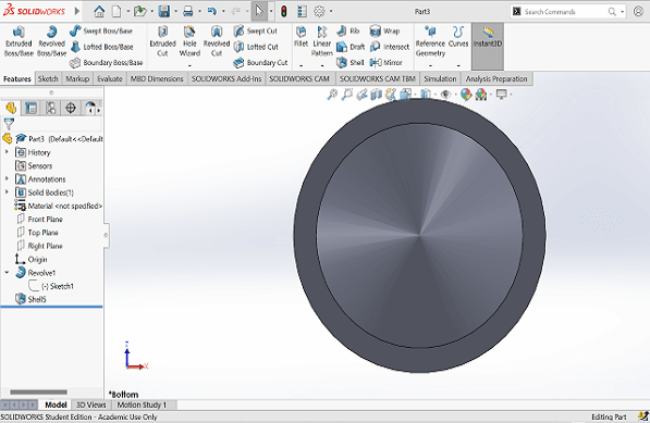
Later, I selected the view using the tool on the graphics screen. I can select one of the views like, top, bottom, right, left, isometric, etc. from, which I want to visualize the 3D object. I selected bottom view like the one in the image below.
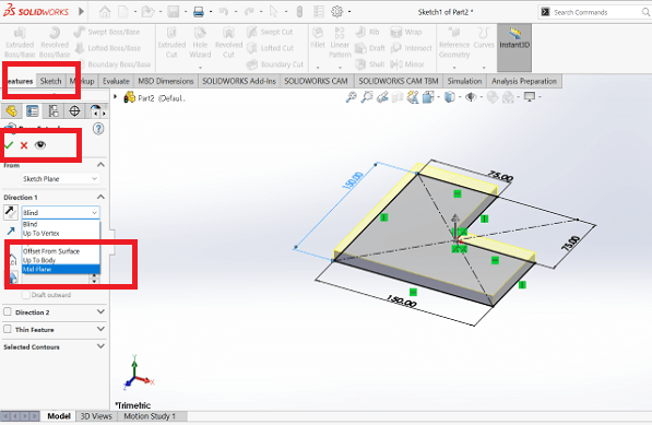
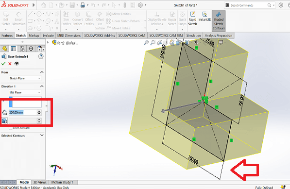
Then, I drew new sketch to try trim entities and extrude across the Mid plane. I drew two rectangles, one overlapping the other. I drew the second rectangle using draw rectangle using corner command as shown in the images below. I then used trim entities command to trim the edges of the overlapping surfaces of these two rectangles. I then extruded this L shape at a certain depth equally across the Mid plane (sketching plane).
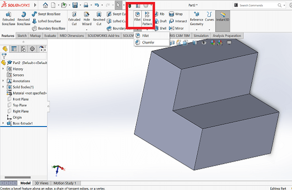
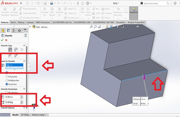
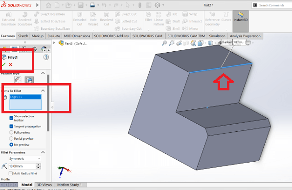
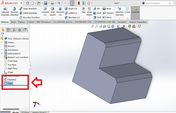
Lastly, I applied champer and fillet using the tool on the top. I selected edges, gave dimensions and created champer and fillet on the edges shown in the images below.
Creating 3D objects and Assembly of Parts of my Final Project in Solidworks
I used SolidWorks to create 3D models of some of the parts of my Final project. I also used Assembly module to create a basic assembly of my final project. I used rendering to change the appearance, texture and colors of the components.
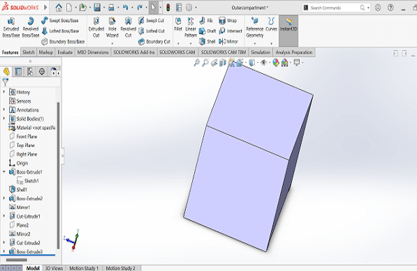
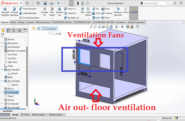
First, I created 3D models of some of the major parts of my final project concept. I used extrude, shell, cut extrude command majorly to create these parts. First model was the external compartment of a storage rack as shown below.
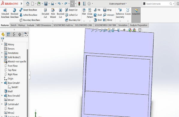
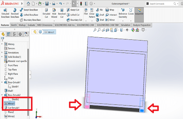
Then, I used mirror command to create resting and lifting channels at the bottom and the slots for assmebling the ventilator fans along one of the sides of the storage compartment as shown below.
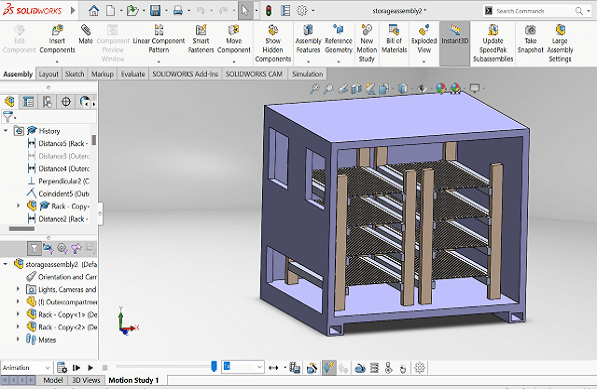
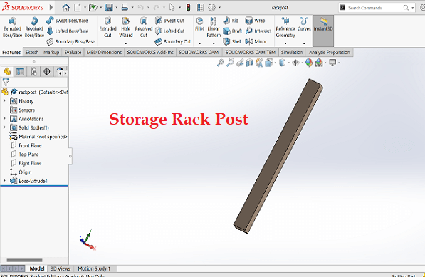
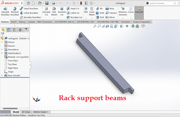
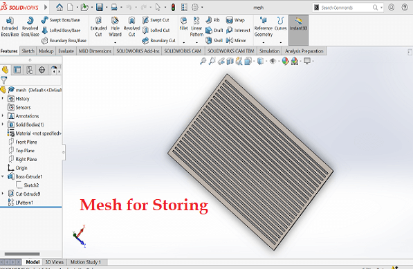
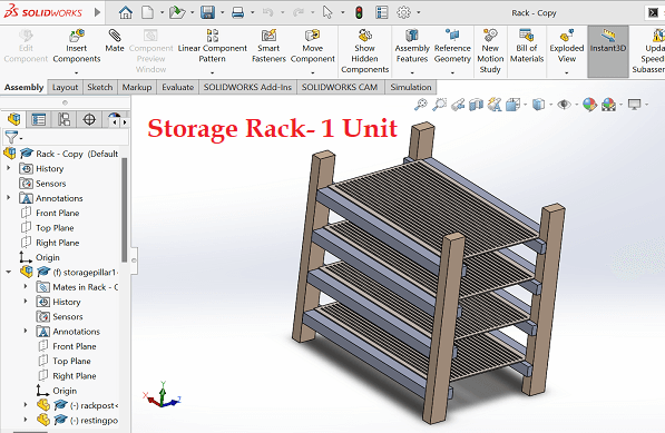
I created 3D models of parts of the storage rack and used assembly module in Solidworks to develop the sub-assembly of a storage rack.
I created final assembly of the storage house using the assembly module in Solidworks
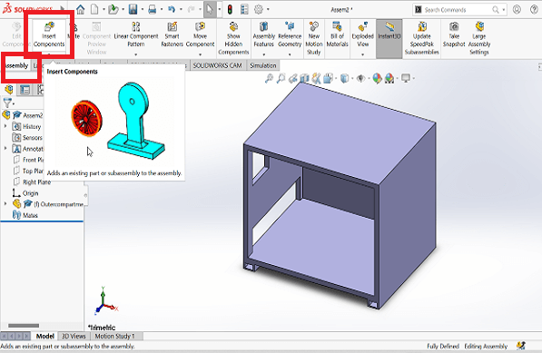
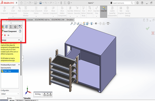
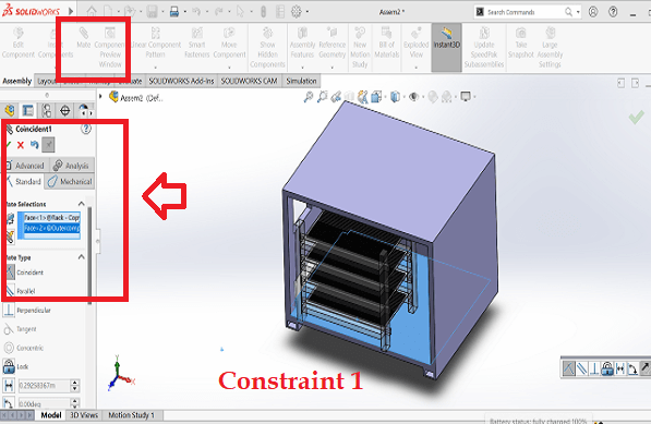
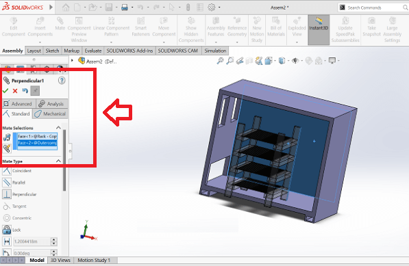
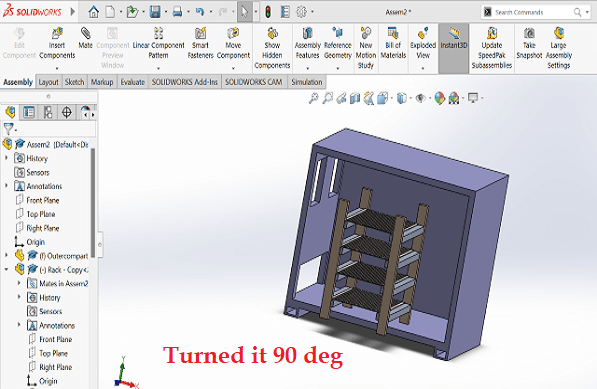
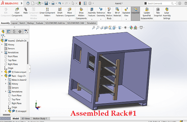
I used insert compoents and Mate parts to assemble 2 racks in to the compartment.
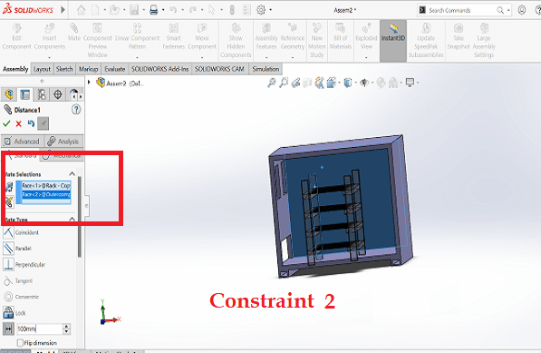
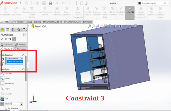
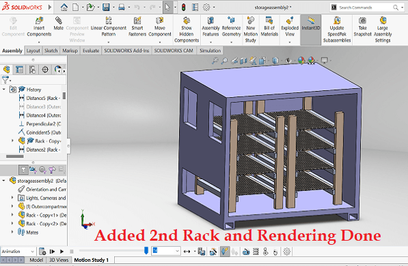
I continued to use Mate command to constraint rack in to the compartment until it was assembled at the desired location. Similarly, I assembled the second rack and finally used rendering tool to give studio view, spotlight, etc. to the final assembly of the compartment. I am yet to add many parts like electronics, sensor casings, ventilator fans, closing panels, etc.
I used animation wizard in Solidworks to create a small animation of the final assembly for better visualtion of the project through animation. Please find below the video.
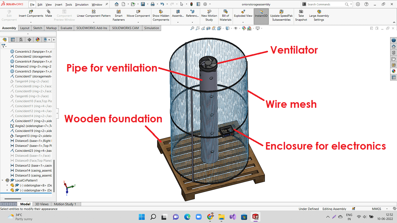
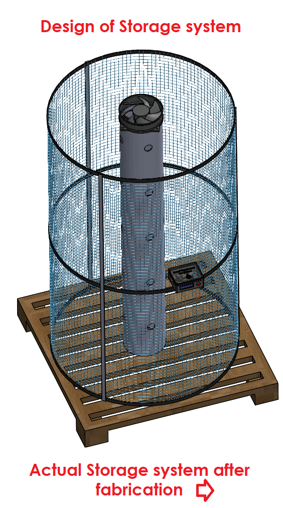
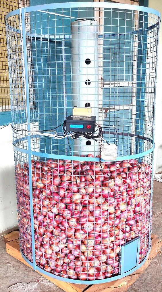
However, this design was my initial thought. I later decided to design and set-up cost-effective storage system that is most common amongst the farmers in our nearby farm community. Following is my new design.
Following are the pictures of storage system designed and actual storage system I fabricated. I arranged these two pictures side-by-side to compare designed vs actual set-up.
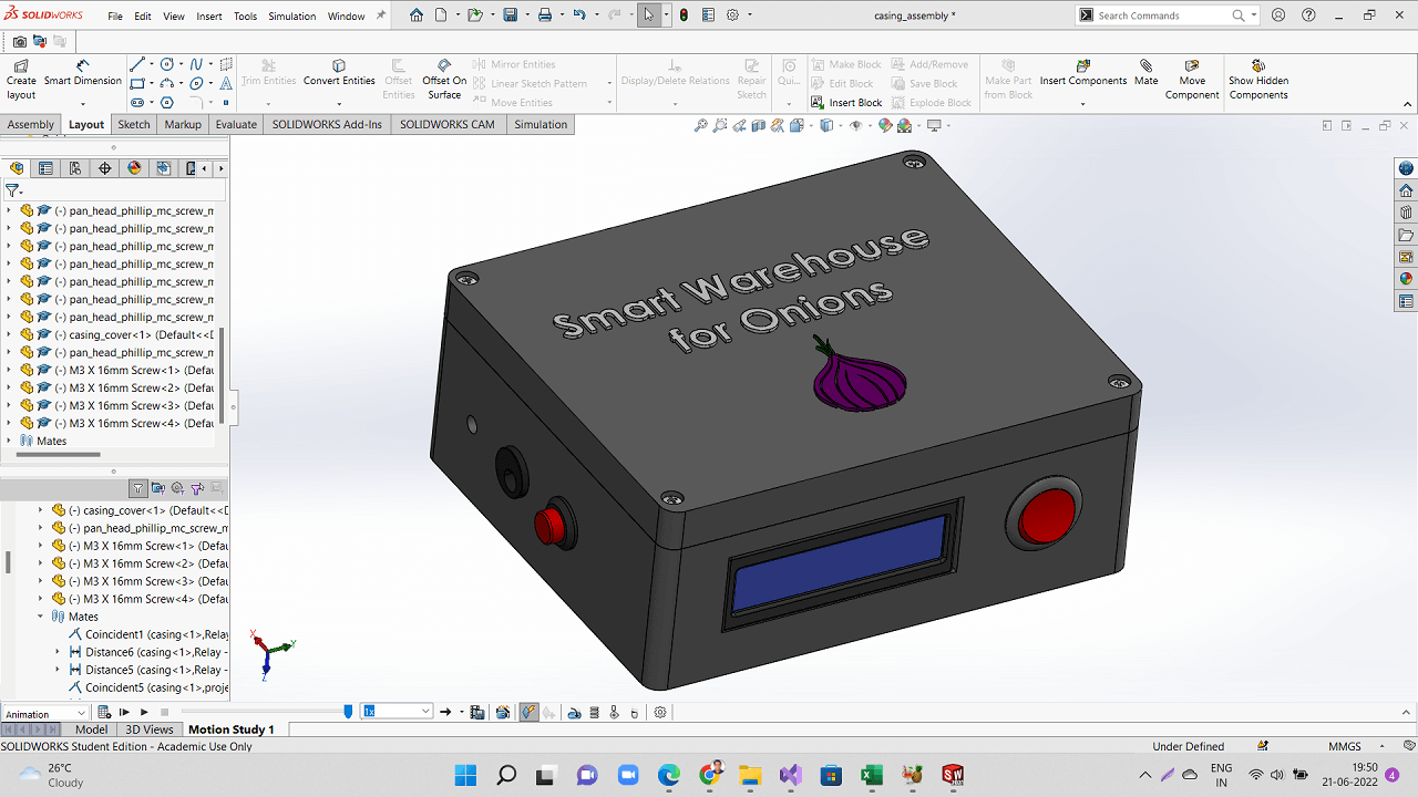
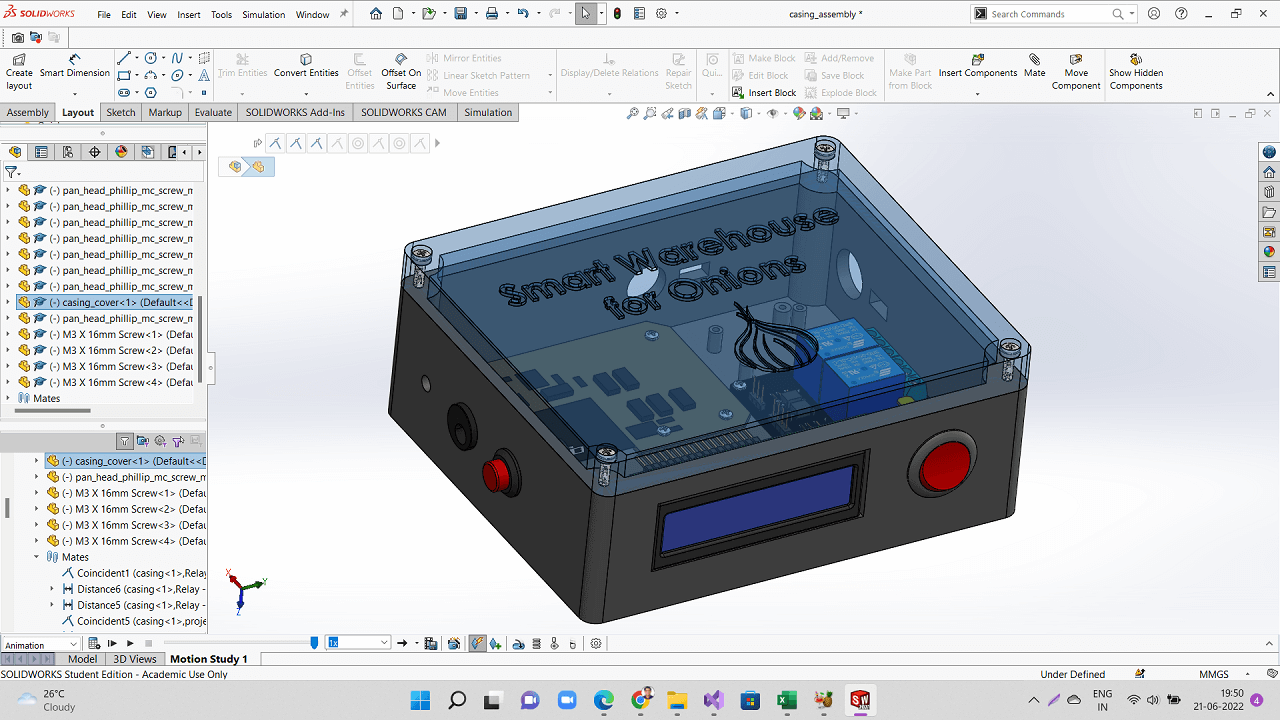
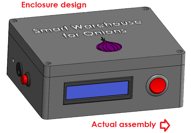
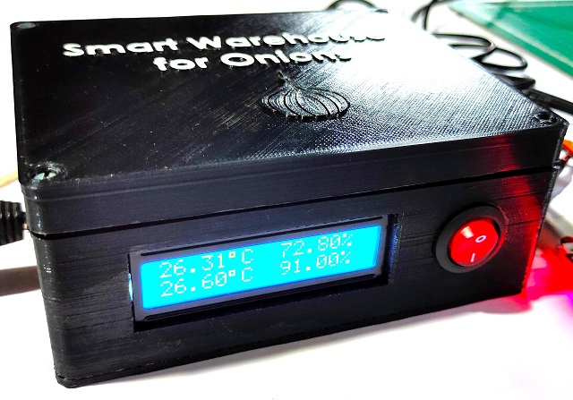
Following is a picture of the CAD model that I later designed for 3D printing the enclosure for electronics of the system.
Following are the pictures of enclosure designed and actual enclosure I 3D printed and assembled. I arranged these two pictures side-by-side to compare designed vs actual assembly.
Difference between 3D CAD tools
In Solidworks, it is easiar to build large assemblies as compared to doing it in the FreeCAD
In Solidworks, the UI makes it easier to select, edit, the planes, sketches as compared to FreeCAD
Both FreeCAD and Solidworks use Parametric modeling. However, it is easier in Solidworks
In Solidworks, we can view animation of the assembly files but It is not available in FreeCAD
In FreeCAD, there are multiple interfaces like Sketcher, Part Design, A2 workbench, etc. that we need to keep switching between each other. This becomes tedious at times. In Solidworks, the UI is quite better and easy for anyone to go from one menu to the other
Image editing and resizing is important for all my documentation in Fab academy. I will be capturing and collecting huge number of images during my work. It is very much necessary to keep all my folders including images organized.
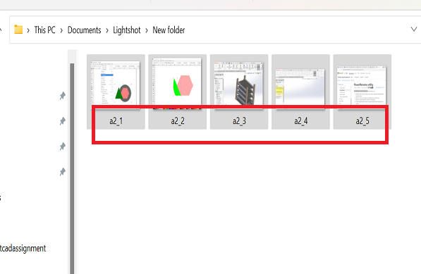
When I capture images using any of the screenshot software, they get automatic nomenclature. However, when I keep all these images in asset sub-folder, their nomenclature might have conflicts as they may get same names given automatically by the screenshot applications.
Since I need to keep a watch on the cloud storage utilization without compromising on the number of images used in documentation. I therefore need to use image resizer software that reduces the size of the images without disturbing the original quality of the images much. So batch renaming of images in standard nomenclature format as per the assignment and batch resizing is needed during the fab academy work.
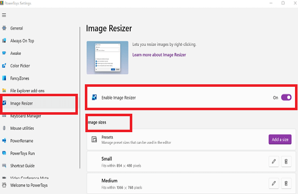
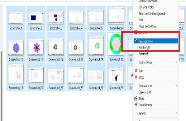
With a simple right click from File Explorer, resize one or many images instantly. Image Resizer also allows you to resize images by dragging and dropping your selected files with the right mouse button. This allows you to quickly save your resized pictures in a different folder.
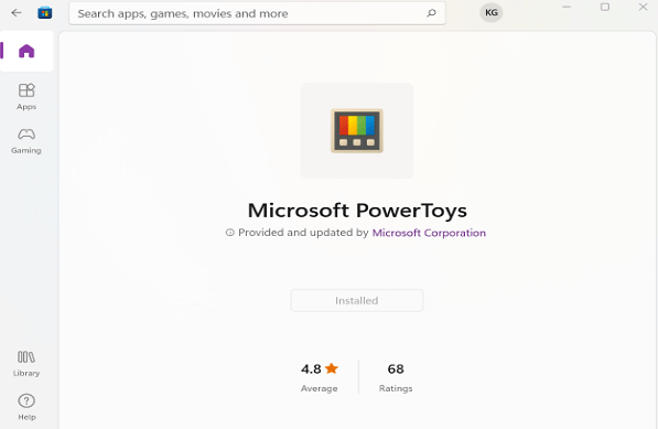
Install Windows Power toys from Microsoft store and set defaut settings first.
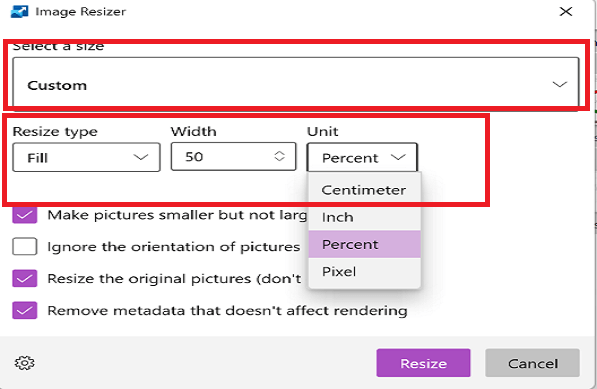
Select all the images to be resized, right click and go to Resize Pictures option. One can set new size of the image in terms of percentage, pixel, inch, etc. or you can choose custom sizes from the drop down above. These custom sizes are as per your default settings done in power toys.
Windows Power Toys- Power Rename Utility
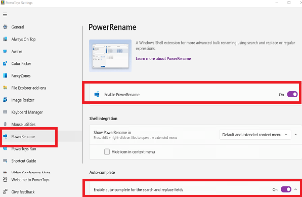
Power Rename is a bulk renaming tool that enables one to: 1) Modify the file names of a large number of files (without giving all of the files the same name), 2) Perform a search and replace on a targeted section of file names, 3) Perform a regular expression rename on multiple files, 4) Check expected rename results in a preview window before finalizing a bulk rename and 5) Undo a rename operation after it is completed.
Install Windows Power toys from Microsoft store and set defaut settings first. Select all the images to be batch renamed, right click and go to PowerRename option.
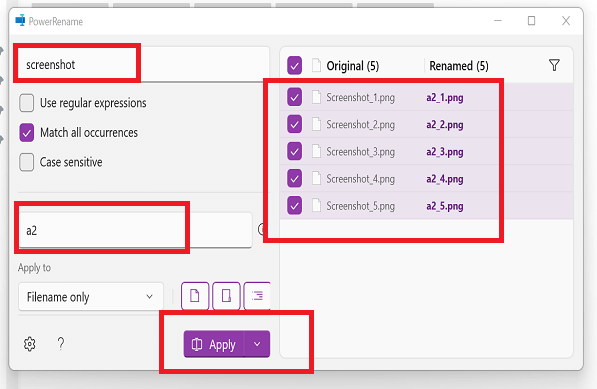
In to the UI of the tool, you can search a pattern of words to be replaced in to the file name and replace it with a new pattern. On the right hand side of the tool, you can see how old file nomenclature and how file names are going to be replaced with after bulk processing. Hit Apply button upon confirming if the new names are correct as per your requirements. You can find the files renamed in to the destination folder as per new nomenclature as shown in the image below.
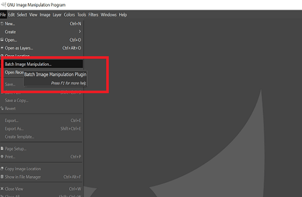
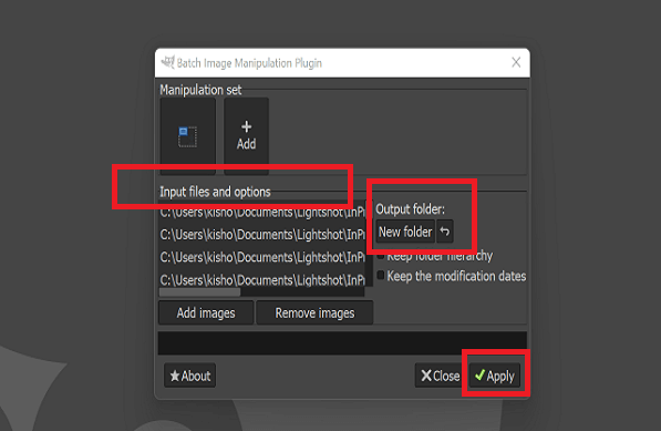
BIMP Batch Image Manipulation Plugin for Resizing and Renaming
Upon installing, this Plugin for GIMP, batch image manipulation button starts appearing under File menu of GIMP software.
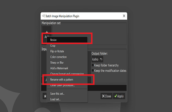
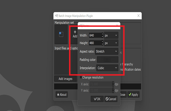
Select and add one of the manipulation sets such as Resize, Crop, Batch Rename with Pattern, etc. After selecting the Resize set, we can apply resize settings like image width, height, aspect ratio, etc. Finally, add images in bulk from a folder, choose destination folder for resized images and hit apply button to process.
Video editing and resizing is also important for all my documentation in Fab academy. I will be creating, shooting and collecting a huge number of videos during my work. I also need to present my work very effectively in a shortest possible time. For that reason, Videos are the best means for presentation. I need to create a very good videos by adding text, animations, with or without any sound, removing background noise, etc. For that reason, I need to learn the video making and editing software.
Also, when I capture or create any videos using HD camera or any of the CAD software, they are of high resolution and original file size of these videos will be too large. Since I need to keep a watch on the cloud storage utilization without compromising on the number of videos used in documentation. I therefore need to use video editor and maker software that reduces the size of the videos without disturbing the original quality of the videos much.
Movavi Video Suite 2022 is a commercial software for video making and editing. HandBrake is an open source video editing and converting tool. I used both these tools for my practice and work.
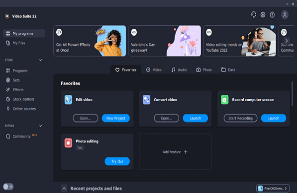
Movavi Video Suite 2022
Movavi is an all-in-one video maker: an editor, converter, screen recorder, and more. It has simple interface with intuitive controls and it takes quite less time to create a finished video. It is a fun making videos in Movavi. I used it to make video of my final project demo.
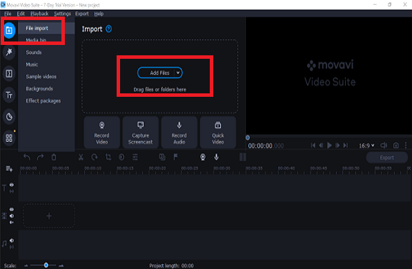
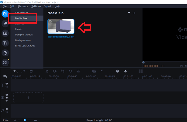
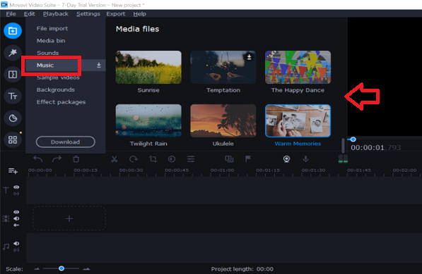
Step 1: Import or drag and drop input video file using Import menuof the Movavi UI. Your file will appear in to the Media bin of the application.
Step 2: Download standard sound clips, background music files, video clips, background images and some effect packages available in Movavi suite using import menu of the UI.
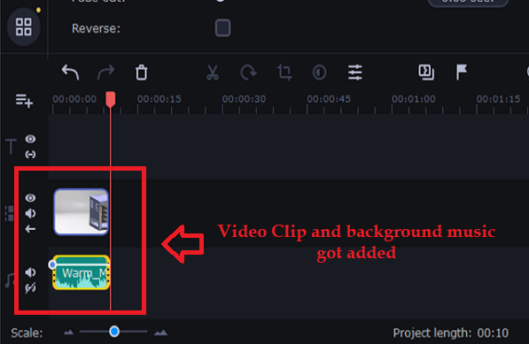
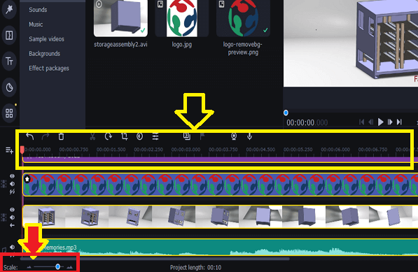
Step 3: Drag files from the media bin (video, audio) into the below working area. We can adjust the scale of the track below. The larger the scale, better it is to place the files at the exact start and end time on the track.
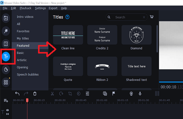
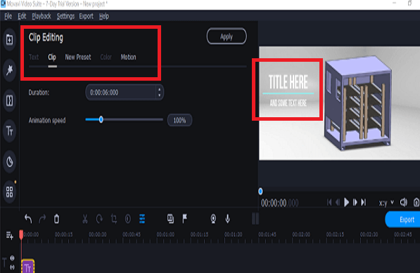
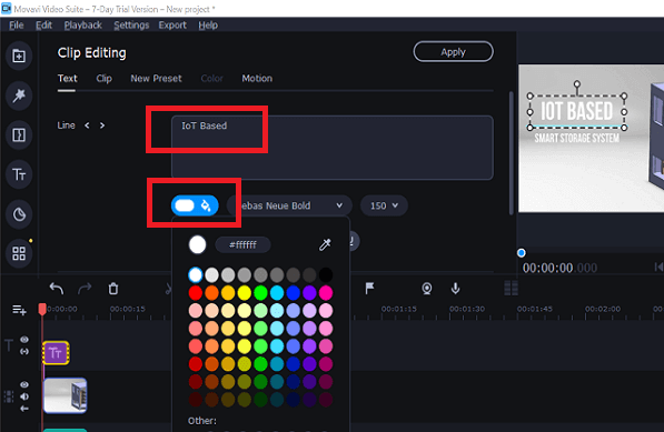
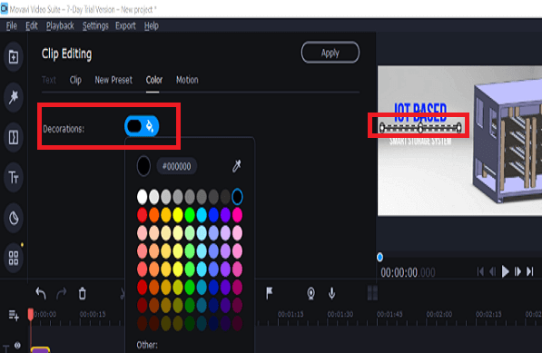
Step 4: Add transition effects, text in to the track. Transition effects are required between two video clip or pictures for better visualization and understanding the flow. We can edit the standard text, clips after adding them to the track as per our requirements. We can change color, placement, time duration, speed, etc. of texts added.
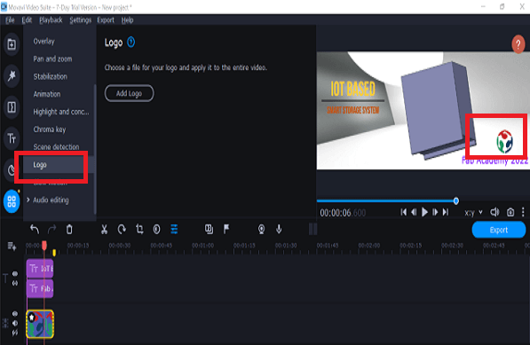
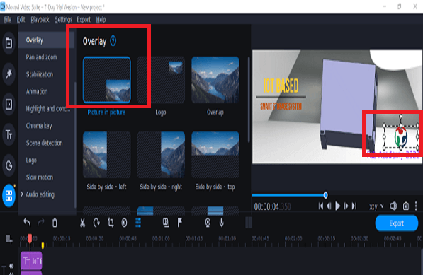
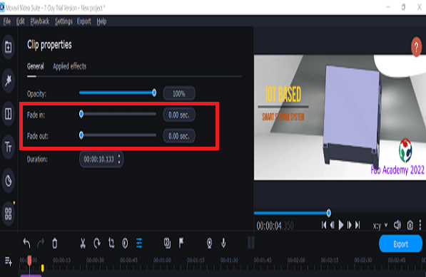
Step 5: We can add logos, stickers, etc. in to the track. We can add our own logo and we can change placement, time duration, speed, fade in and out etc. of the logo added.
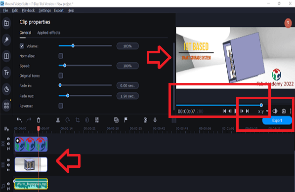
Step 6: We can edit the audio track as per our requirement. We can change placement, time duration, speed, fade in and out etc. of the audio track. At the end, we can preview the video file created in to the top right window before we export the final video.
You can find video file that I have created using Movavi below. This is how part of my Final project will look like.
HandBrake Video Editing Tool
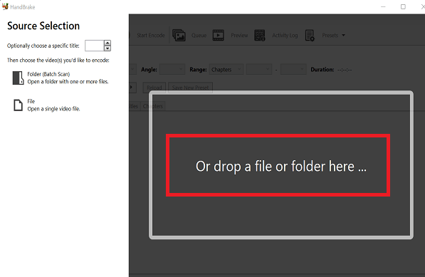
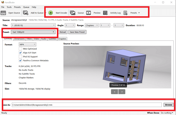
HandBrake is a tool for converting video from nearly any format to a selection of modern, widely supported codecs and can be used to resizing the bulky videos.
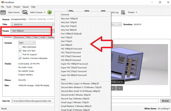
Browse or Drag and drop bulky video file in to the HandBrake UI. Inside the UI, we can find various toolbars like video preview, view queue, destination folder for storing the converted file, selecting resolution of the new file along with its format.
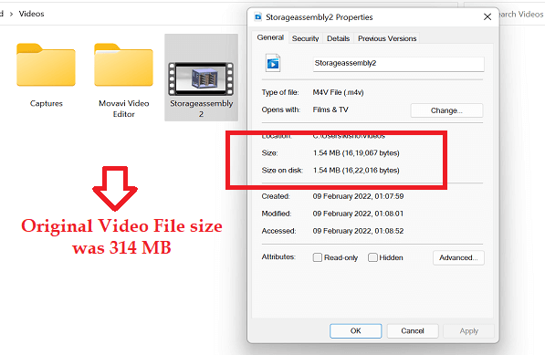
We can then select the desired parameters and click on Start Encode button for conversion. In the second picture below, you can see the size of the original video file is reduced quite drastically from 315 MB to 1.54MB without affecting the resolution of the video file much. It is good enough for my project presentation.
In 2D Design- There are various options to try and practice. The open source software are equally good to use and have more or less features. Planning of my schedule for each of the applications worked well. I could try various tools in the given time period. In 3D Design- Started with FreeCAD first. I referred to some of the tutorial videos. Creating sketches and 3D objects worked well. Solidworks UI was better to work with. In Image and Video Editing- I learned various applications including some of the shell commands and also open source cloud based applications.
In 2D Design- I had some issues with my computer in installing Coreldraw and I spent some time fixing it. Later, I started working with Inkscape. In 3D Design- I made a lot of mistakes in asselmbling parts initially. However, I learned how to assemble parts in Solidworks. It was easy. I need to learn complex motion study. Also, I could not spend more time on Fusion 360 and animation. In Image and Video Editing- Made a lot of attempts in reducing the file size of png images without losing their quality. I used tinypng platform and it worked well.
I will use image renaming and resizing right from the beginning of the assignment documentation. Better folder structure will help. Also, I will ask for help to my fellow academy students in learning new applications.