
Assignment#9: Molding and Casting
This assignment is about documenting what I learned in Molding and Casting that includes basics of molding and casting processes, materials used. I have documented how I used solidworks to design the model, modela player 4 software to create toolpaths. I was able to machine my mold on SRM20, use molding and casting materials to create mold and final casting. I am also documenting what went well, what went wrong, how I would do things differently in next assignment and my learning outcomes.
My Hero shots for this week
 |
 |
 |
 |
Click here to go back to the top
Basics of Molding and Casting
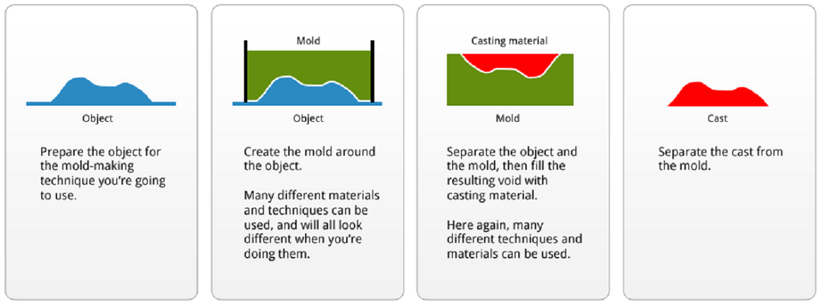
Molding is the process of manufacturing by shaping liquid or pliable raw material using a rigid frame called a mold or matrix. This itself may have been made using a pattern or model of the final object. The liquid hardens or sets inside the mold, adopting its shape. A mold or mould is a hollowed-out block that is filled with a liquid or pliable material such as silcine rubber, plastic, glass, metal, or ceramic raw material. A mold can also be made of wood, MDF carved on a CNC milling machine. A mold is the counterpart to a cast.
Molding is a technique through which a material, often plastic, but also metal, rubber, or powder mixtures is shaped on the outline of a die or mold. There are many different techniques for molding materials, just as there are many different applications for each process. Moulding boxes are special purpose boxes that are designed for use in moulding systems where the demand of high pressure moulding and high production rates (from a fully automated system) require a box designed & machined to exacting tolerances.
Casting is a manufacturing process in which a liquid material is usually poured into a mold, which contains a hollow cavity of the desired shape, and then allowed to solidify. The solidified part is also known as a casting, which is ejected or broken out of the mold to complete the process.
References: Reference#1, Reference#2, Reference#3
 |
Injection Molding
It is a preferred process for manufacturing plastic parts. Injection molding is used to create many things such as electronic housings, containers, bottle caps, automotive interiors, combs, and most other plastic products available today. It is ideal for producing high volumes of plastic parts due to the fact that several parts can be produced in each cycle by using multi-cavity injection molds. Some advantages of injection molding are high tolerance precision, repeatability, large material selection, low labor cost, minimal scrap losses, and little need to finish parts after molding. Some disadvantages of this process are expensive upfront tooling investment and process limitations.
References: Injection Molding
Before we learn more about molding and casting, it is important to learn about some of the basic terminologies and concepts like injection molding process, sprue, runners, parting line, etc.
Injection Molding Process
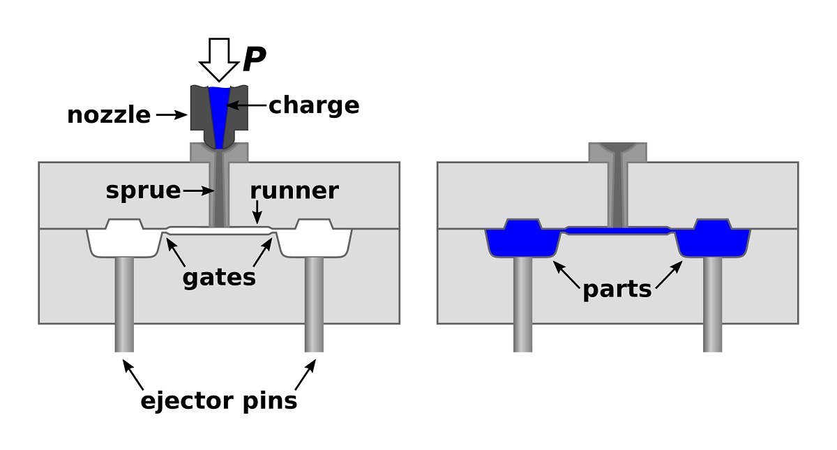
With injection molding, granular plastic is fed by gravity from a hopper into a heated barrel. As the granules are slowly pushed forward by a screw-type plunger, the plastic is forced into a heated chamber called the barrel where it is melted. As the plunger advances, the melted plastic is forced through a nozzle that seats against the mold sprue bushing, allowing it to enter the mold cavity through a gate and runner system. The mold remains at a set temperature so the plastic can solidify almost as soon as the mold is filled.
The sequence of events during the injection molding of a plastic part is called the injection molding cycle. The cycle begins when the mold closes, followed by the injection of the polymer into the mold cavity. Once the cavity is filled, a holding pressure is maintained to compensate for material shrinkage. In the next step, the screw turns, feeding the next shot to the front screw. This causes the screw to retract as the next shot is prepared. Once the part is sufficiently cool, the mold opens and the part is ejected.
Reference Link
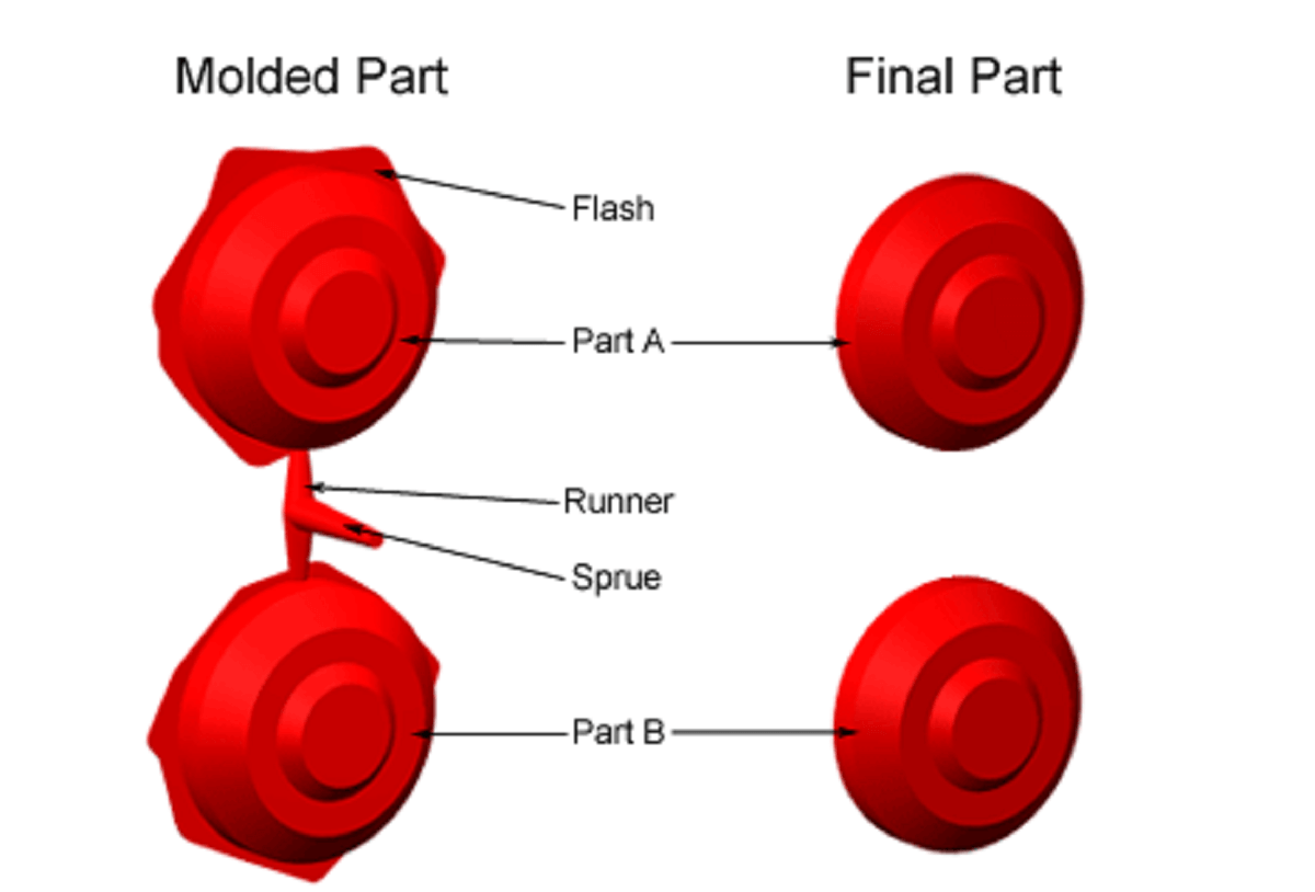
Sprues, Runners and Gates
Sprues and runners are some of the largest pieces of excess material that we remove from moulded parts. They are created deliberately during the moulding process as the method in which the molten material enters the mould cavity.
A sprue is a large diameter channel through which the material enters the mould. A runner is a smaller diameter channel that directs the molten metal towards the individual part (particularly common when casting multiple parts at once). The part where the metal reaches its destination and begins to flow into the mould cavity is called the 'gate'. Metal castings, when solid, need to have this extra material removed, however manufacturers of small plastic models most notably use these as a packaging method.
 |
Vents
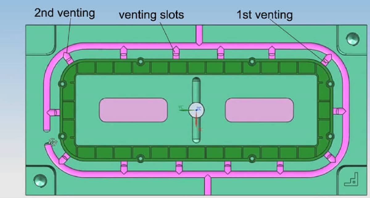
Vents are cuts within the mold steel that allows air to escape. Before injection molding, there is a large amount of air in the flow path and the cavity. When the melt enters the cavity quickly, it is necessary to discharge the air quickly so that the plastic can fill the entire space. In addition, when the melt is solidified in the cavity, there is a vacuum between the product and the cavity wall, also the air must enter the mold in time to help ejection. Without vents, the trapped air will compress as the plastic tries to force the air out of the mold and will cause burning. Generally, a vent should be as large as possible without allowing the plastic to escape.
If the vent is too shallow, the clamping pressure could force it closed. If the vent is too large, plastic could escape and cause flashing. Vents are different sizes based off of what material is being used. Vents should be at the end of flow paths or where flow paths combine. Vents need to be cleaned in order to make sure it does not get clogged and the air can still escape.
 |
Reference Link#1, Reference Link#2
Parting Lines and Flashing
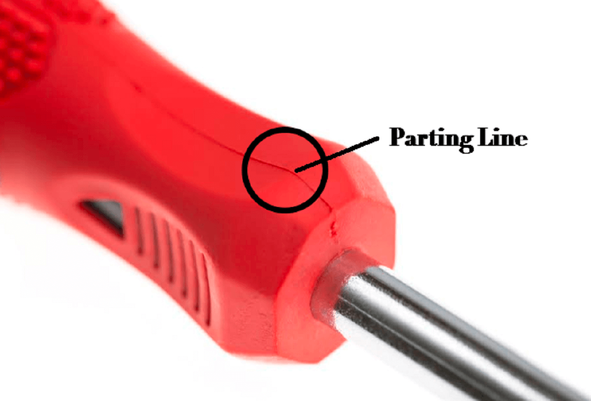
A parting line is the line of separation on the part where the two halves of the mold meet. The line actually indicates the parting "plane" that passes through the part. While on simple parts this plane can be a simple, flat surface, it is often a complex form that traces the perimeter of the part around the various features that make up the part's outer silhouette. Part lines can also occur where any two pieces of a mold meet. This can include side action pins, tool inserts and shutoffs. Parting lines cannot be avoided; every part has them. Keep in mind when designing your part, that the melt will always flow towards the parting line because it is the easiest place for the displaced air to escape or vent.
Flash or flashing is the material that is left on the casted part due to the 'seam' of the mold. The material enters into the seam of the mold slightly and when removed from the mold leaves a thin wafer of material attached. This is common and easy to remove with simple methods. Whilst simple to remove and clean, great care must be taken when designing a mould to ensure that the flashing will not interfere with the function (or aesthetics, if important) of the final product. This can be particularly relevant in parts with high tolerances, friction fits or areas that require a seal. Our experienced mould designers and tool makers will work with you and your product designers to ensure that any seam lines are non-obtrusive and hidden.
 |
 |
Reference Link#1, Reference Link#2, Reference Link#3, Reference Link#4, Video Reference Link
Multi-Cavity and Family Molds, Sprues and Runners
Insert Molding
Overmolding
Vacuum forming
Tabletop vacuum forming- best for makers
Blow Molding Process
Blow Molding Animation
Rotational Molding Process
Rotational Molding Animation
Investment casting Process
Click here to go back to the topMaterials used
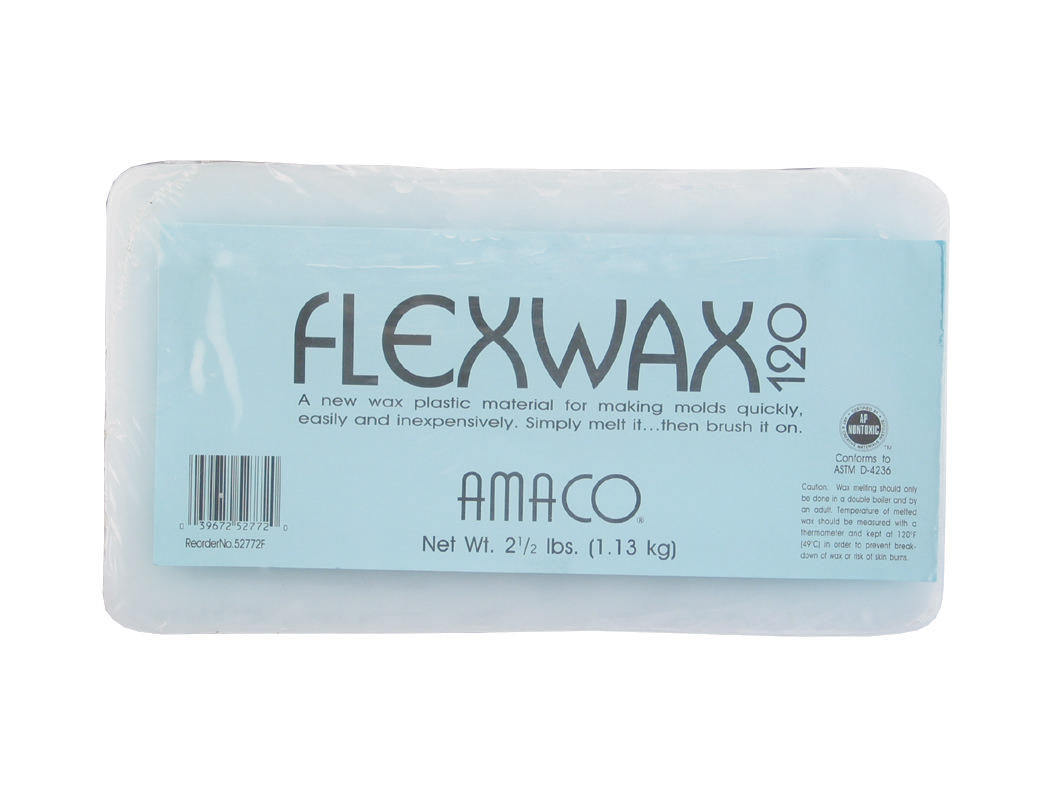
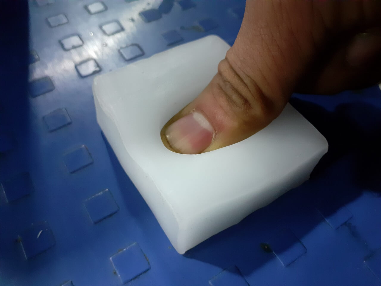
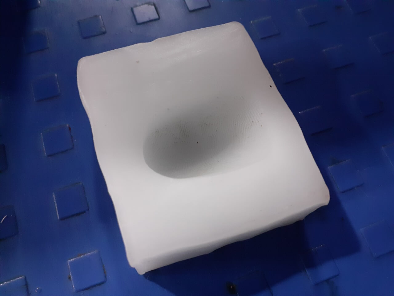
1. Flexwax
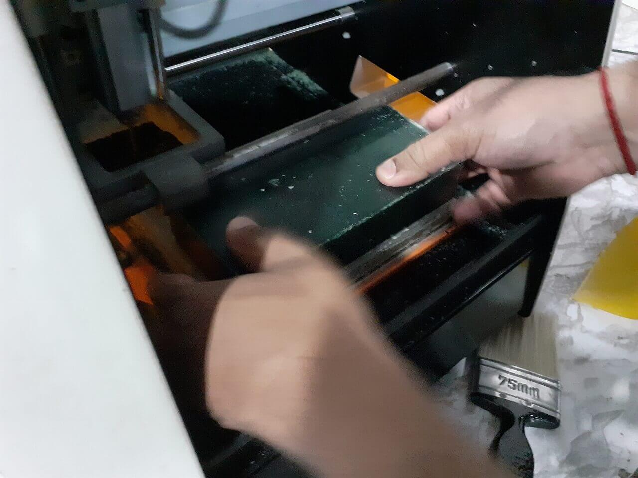
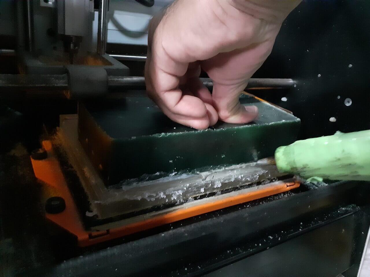
Perfect for making molds from three dimensional objects by simply melting, brushing it on, and allowing to harden. Molds made with Flexwax can be remelted and used again and again. A wax-plastic material for making molds quickly, easily, and inexpensively. Flexwax melts at 120 Deg F (49 Deg C) , a comfortably warm temperature. It cools in a few minutes to form a tough, flexible mold.
This versatile mold making material is easy to use -- simply melt it then brush it on. Ideal for use with three dimensional objects, making face masks, casting hands, etc. At room temperature, the mold is moderately flexible, so you can allow some shallow undercuts without any problem. Molds made with Flexwax can be remelted and used again and again.
 |
 |
||||||||||||||||||||||||||||||||||||||||||||||||||||||||||||||||||||||||||||||||||||||||||||||||||||||||||||||||||
 |
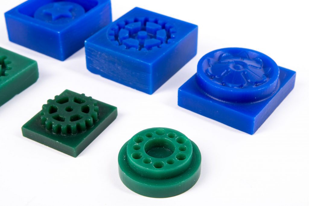
2. Machinable wax
Machinable wax is a term for an exceptionally hard synthetic wax mixed with plastic that features great machining properties, quality of finish, and dimensional accuracy. The material is recyclable and reusable, and is used to produce accurate molds, prototypes, and jewelry.
Machinable wax is an extremely hard wax that has been formulated to deliver exceptional machining properties including high resolution detail. Since it is harder and has a higher melting temperature than most other waxes, machinable wax can be machined, cut, or shaped using standard metalworking or woodworking equipment. High quality surface detail and dimensional accuracy are possible. Machinable wax is ideal for verifying CNC machining programs. Machinable wax is often used for precision lost wax casting. It is available in both blocks and cylinders. It features a combination of properties unique to the tooling and prototyping world. Most notable is its non-abrasive, self-lubricating, and self-releasing characteristics, which make it an ideal material for many challenging applications.
The shavings and unused pieces of material can be re-melted and formed back into useable material. This attribute can substantially reduce the cost of using machinable wax over other materials. The self-releasing properties of machinable wax make it an ideal choice to use as a master model. Epoxies and polyurethanes can be poured directly onto the wax surface without the need for sealers or release agents.
 |
 |
Reference#1, Reference#2, Reference#3
3. Silicone Rubber
Silicone rubber is an elastomer (rubber-like material) composed of silicone-itself a polymer-containing silicon together with carbon, hydrogen, and oxygen. Silicone rubbers are widely used in industry, and there are multiple formulations. Silicone rubbers are often one or two part polymers, and may contain fillers to improve properties or reduce cost. Silicone rubber is generally non-reactive, stable, and resistant to extreme environments and temperatures from - 55 to 300 deg C (-70 to 570 deg F) while still maintaining its useful properties. Due to these properties and its ease of manufacturing and shaping, silicone rubber can be found in a wide variety of products, including voltage line insulators, automotive applications; cooking, baking, and food storage products. Reference- Read more.
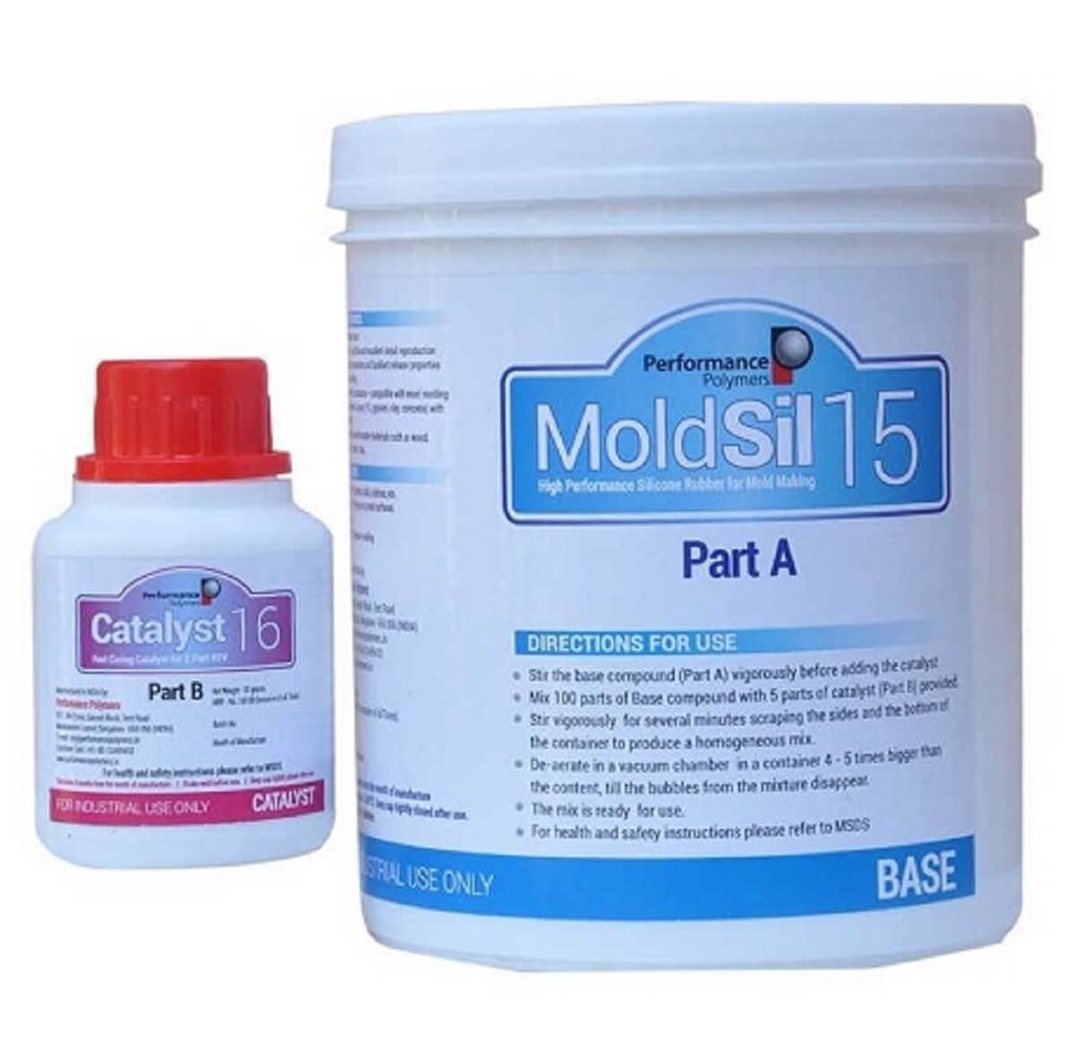
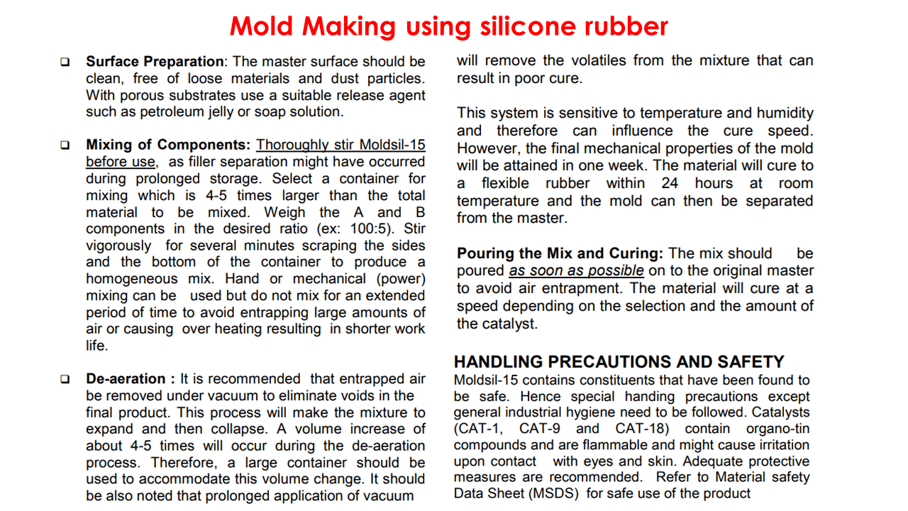
Moldsil-15 Plus Silicone rubber- (Part-A): Moldsil 15 plus is a room temperature Vulcanizing Silicone Rubber for making strong and flexible molds for excellent reproduction of the master and having superb release characteristics. It is compatible with various master and casting material s. This grade has been specially designed to create molds with long life.
This is a flowable grade, having high mechanical strength and cures with various catalyst options (depending on the application requirements) at room temperature to a flexible elastomer, well suited for detailed and exact reproduction of artifacts, figures, architectural items and similar objects. Moldsil-15 PLUS will reproduce the finest detail of the master and is suitable for a variety of art related and industrial applications such as mold making for reproducing prototypes, furniture, architectural items and sculptures.
Features:
- Flowable type high strength silicone rubber curing at room temperature- Excellent detail reproduction.
- Good mechanical properties - leading to long service Life. It is uitable for deep undercut molding.
- Highly elastic and excellent release properties- for easy de-molding.
- Excellent chemical resistance - compatible with most molding materials with long service life.
- Low viscosity - easy flow and excellent detail reproduction.
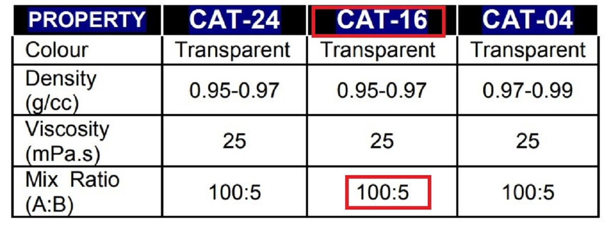
Catalyst (Part-B): The choice of catalyst depends on the application method and the speed of cure needed. Moldsil-15 can be cured in to elastomeric products using the following cure options:
1. CAT-24: Slow catalyst,Takes about 24 hours at room temperature.
2. CAT-16: Medium speed Catalyst,Takes about 16 hours at room temperature.
3. CAT-04: Rapid Catalyst,Takes about 4 hours at room temperature
 |
 |
 |
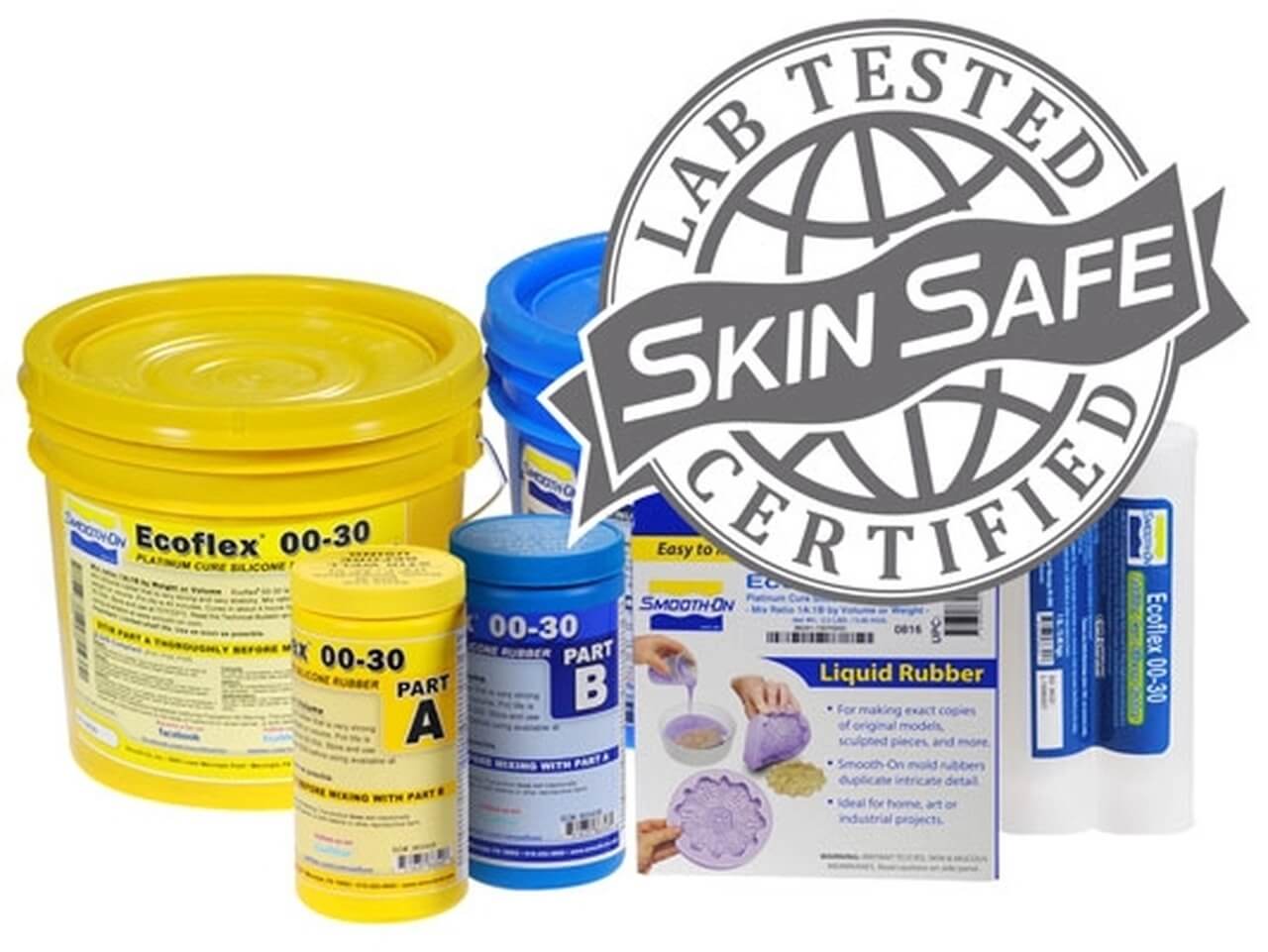
Ecoflex Series Silicone rubber: Ecoflex rubbers are platinum-catalyzed silicones that are versatile and easy to use. Ecoflex rubbers are mixed 1A:1B by weight or volume and cured at room temperature with negligible shrinkage. Low viscosity ensures easy mixing and de-airing. Cured rubber is very soft, very strong and very stretchy, stretching many times its original size without tearing and will rebound to its original form without distortion. Reference- Read more.
Measuring and Mixing - Before you begin, pre-mix Part B thoroughly. After dispensing required amounts of Parts A and B into mixing container (1A:1B by volume or weight), mix thoroughly for 3 minutes making sure that you scrape the sides and bottom of the mixing container several times. After mixing parts A and B, vacuum degassing is recommended to eliminate any entrapped air in liquid rubber.
 |
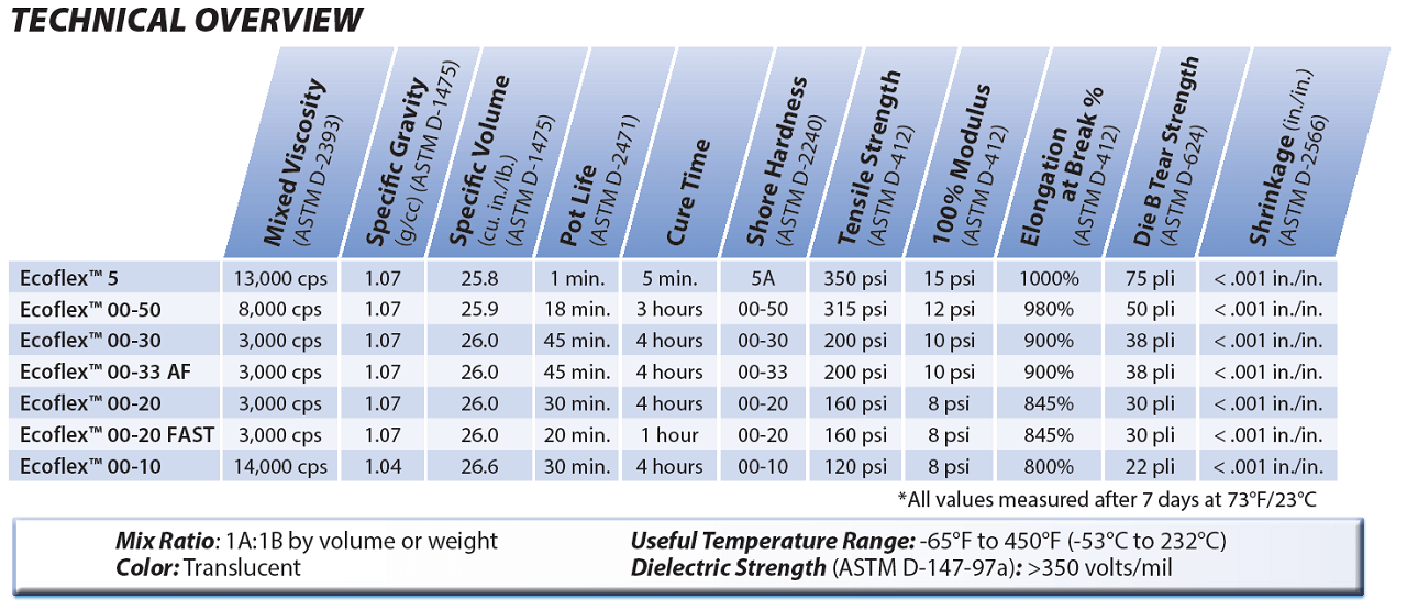 |
Reference for Data sheet of Ecoflex Series Silicone rubber
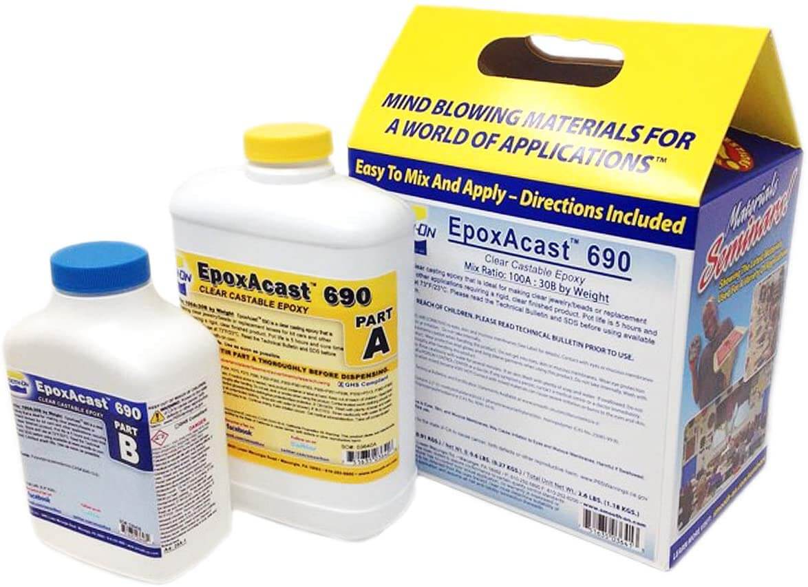
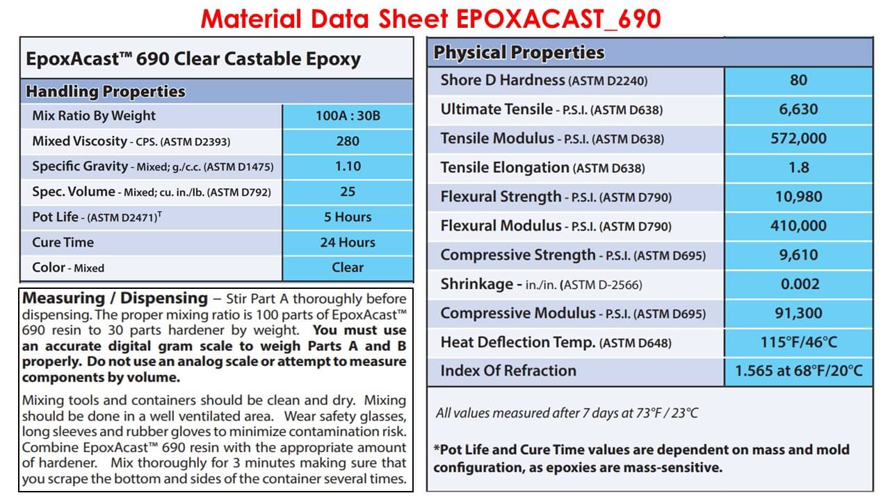
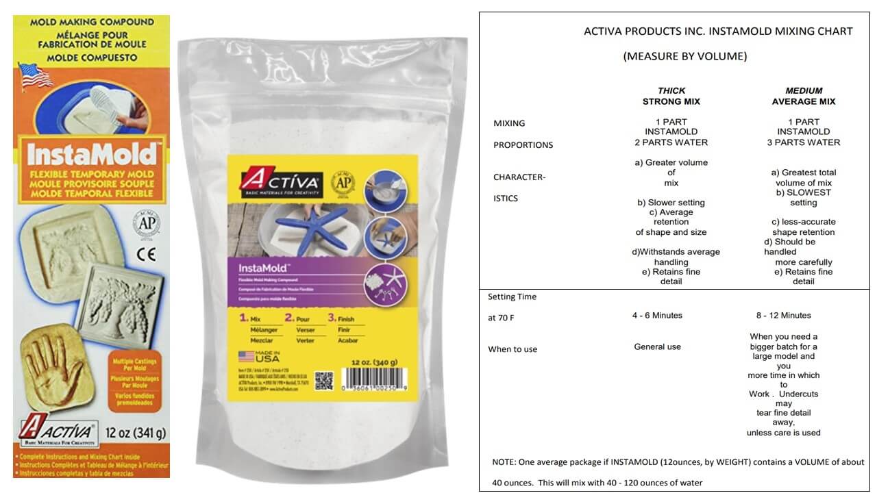
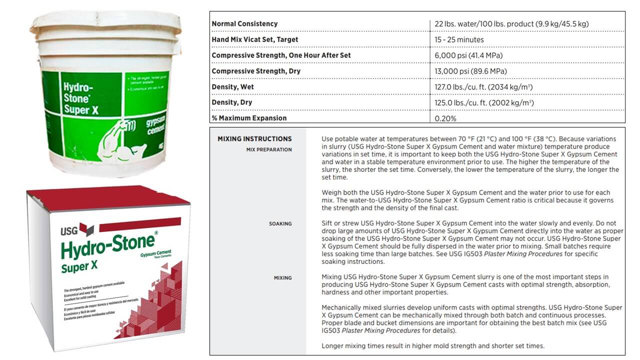
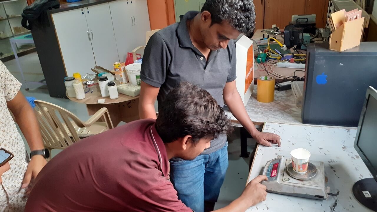
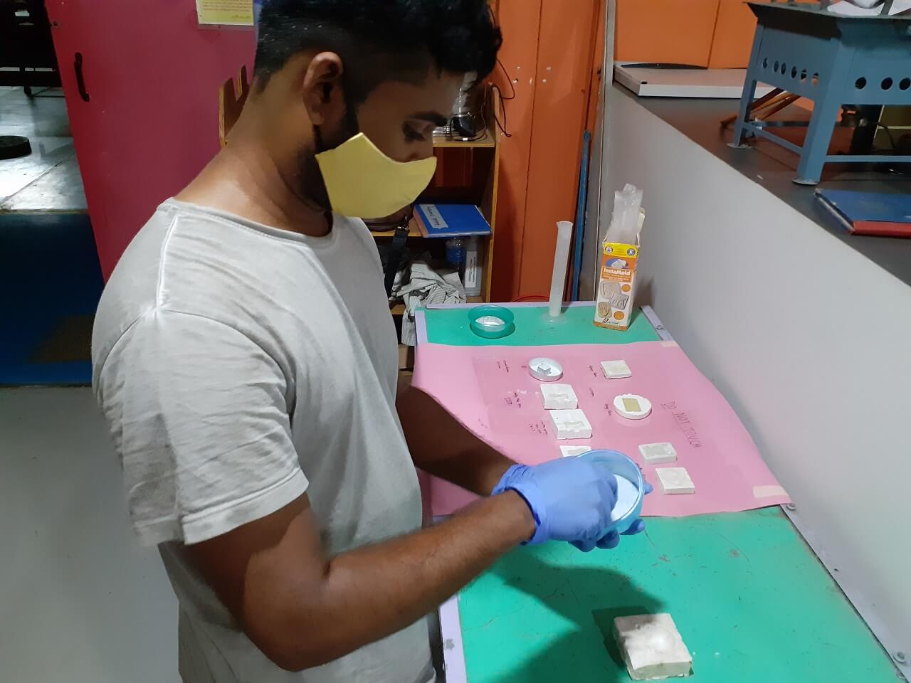
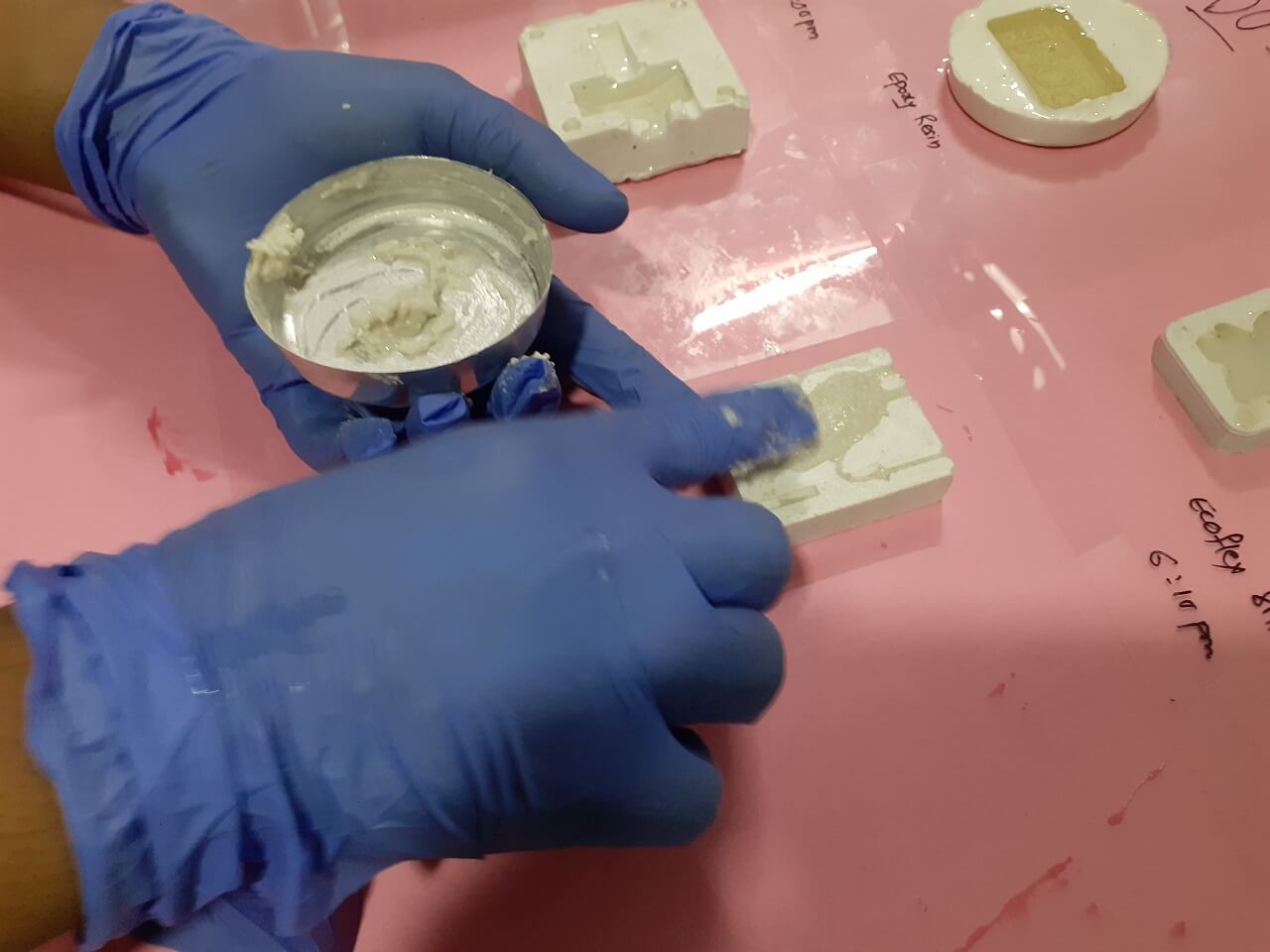
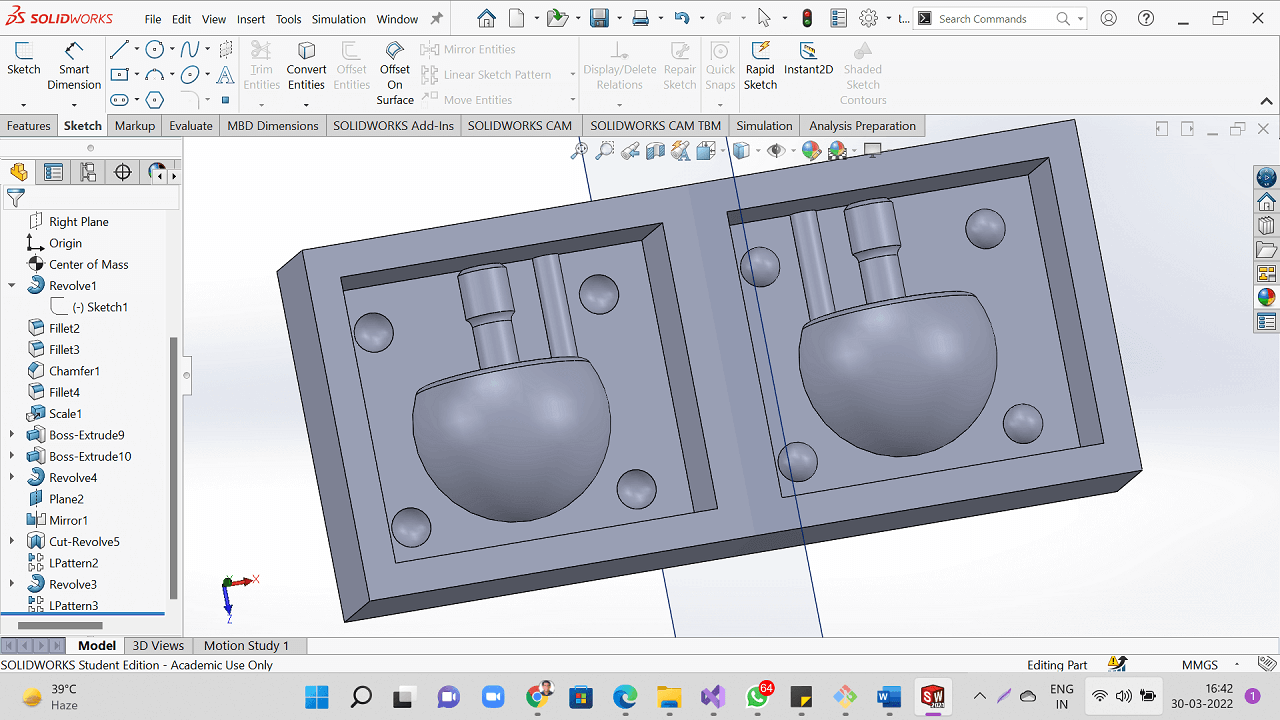
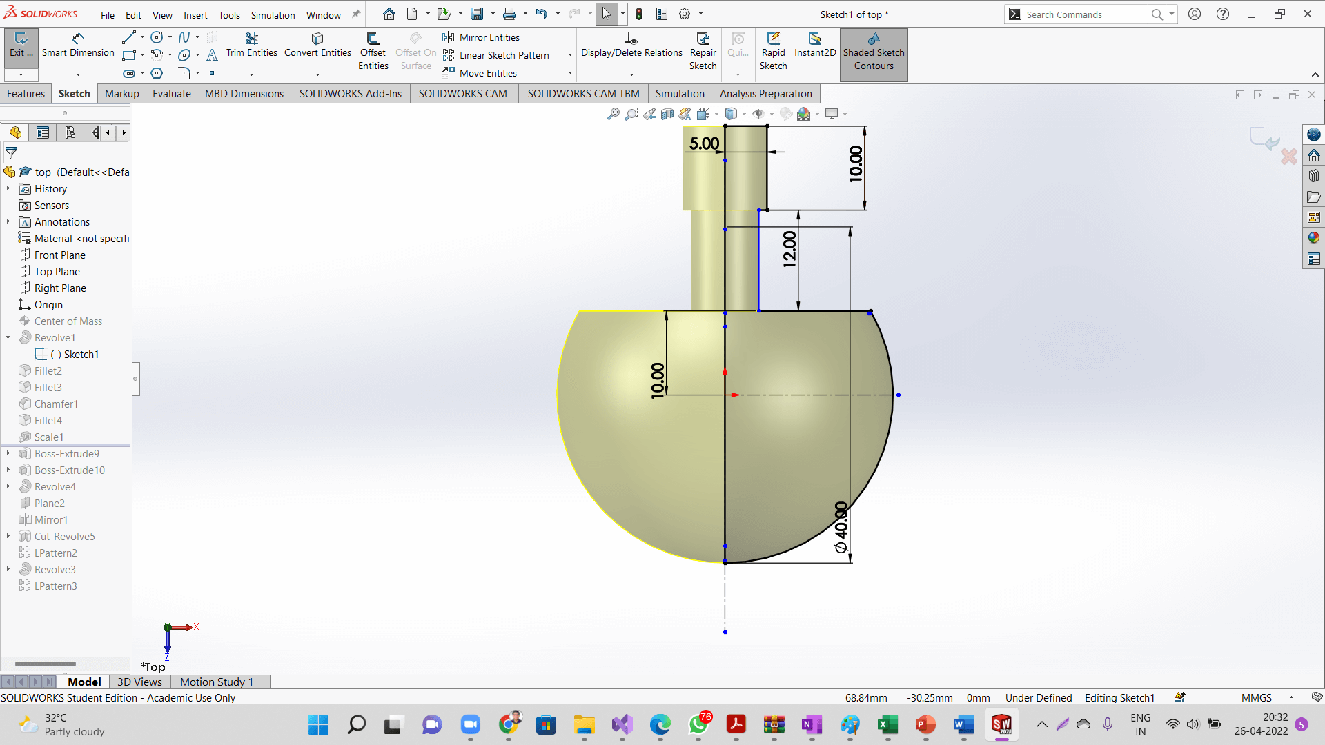
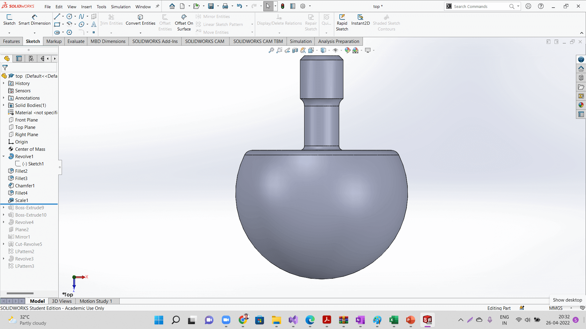
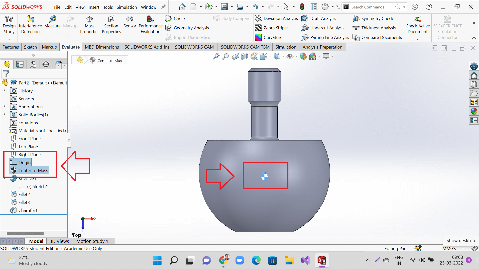
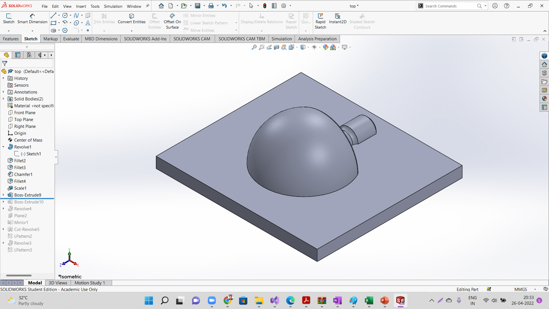
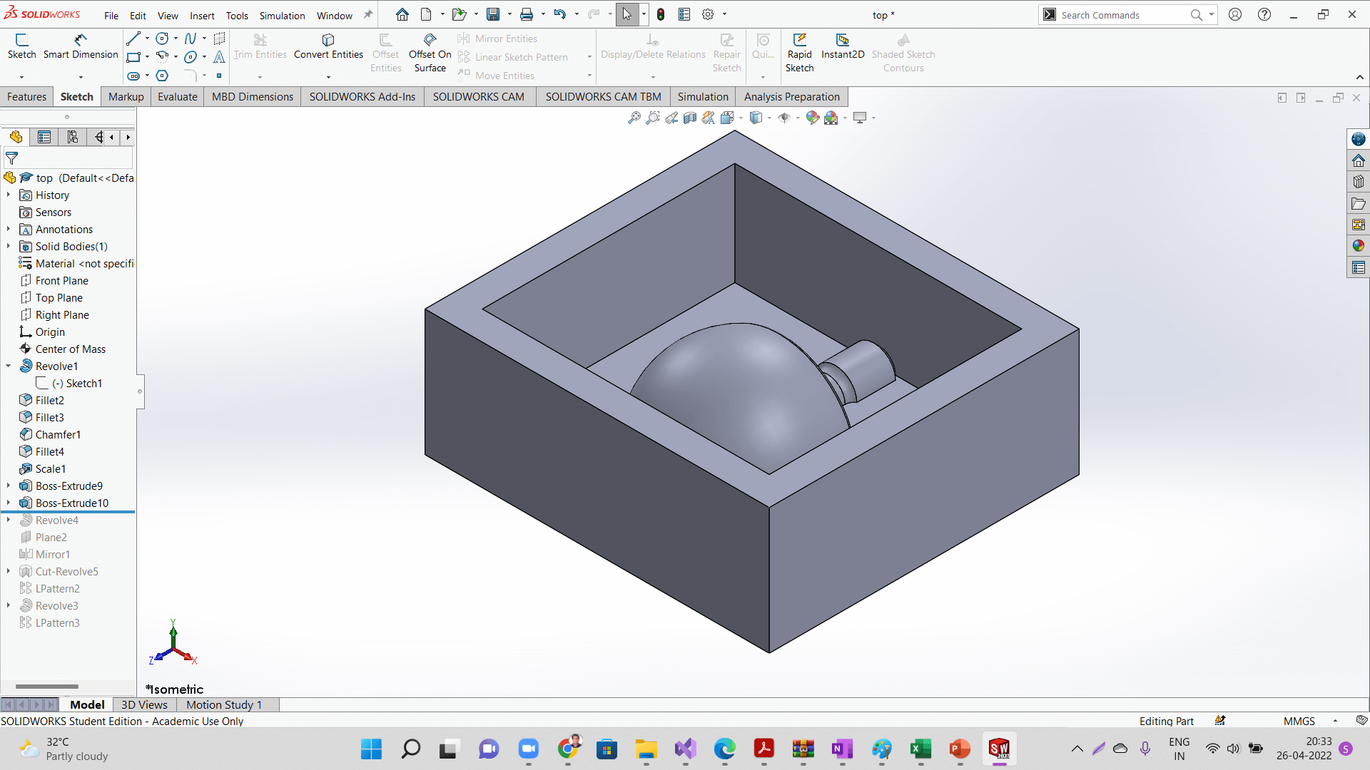
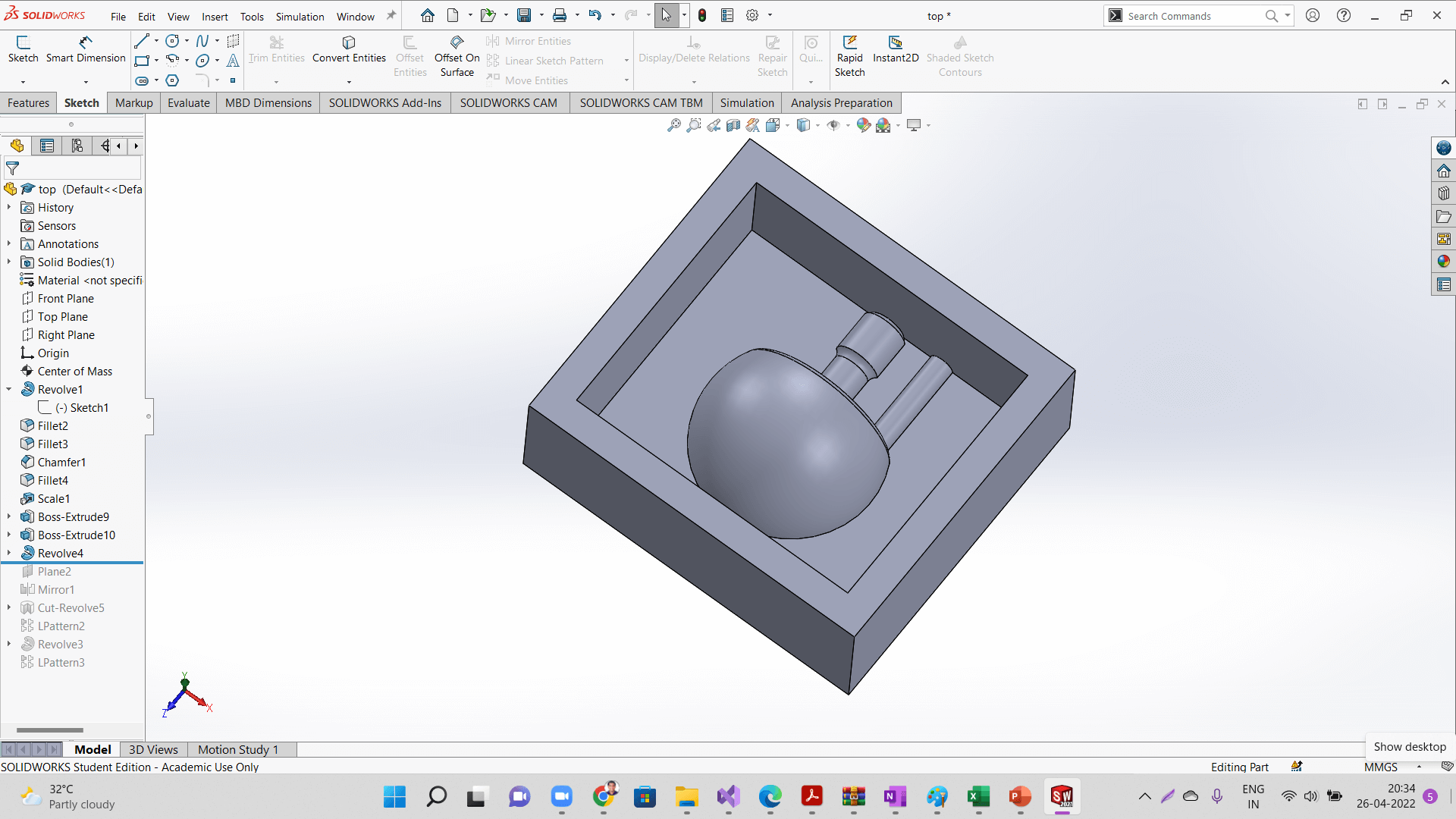
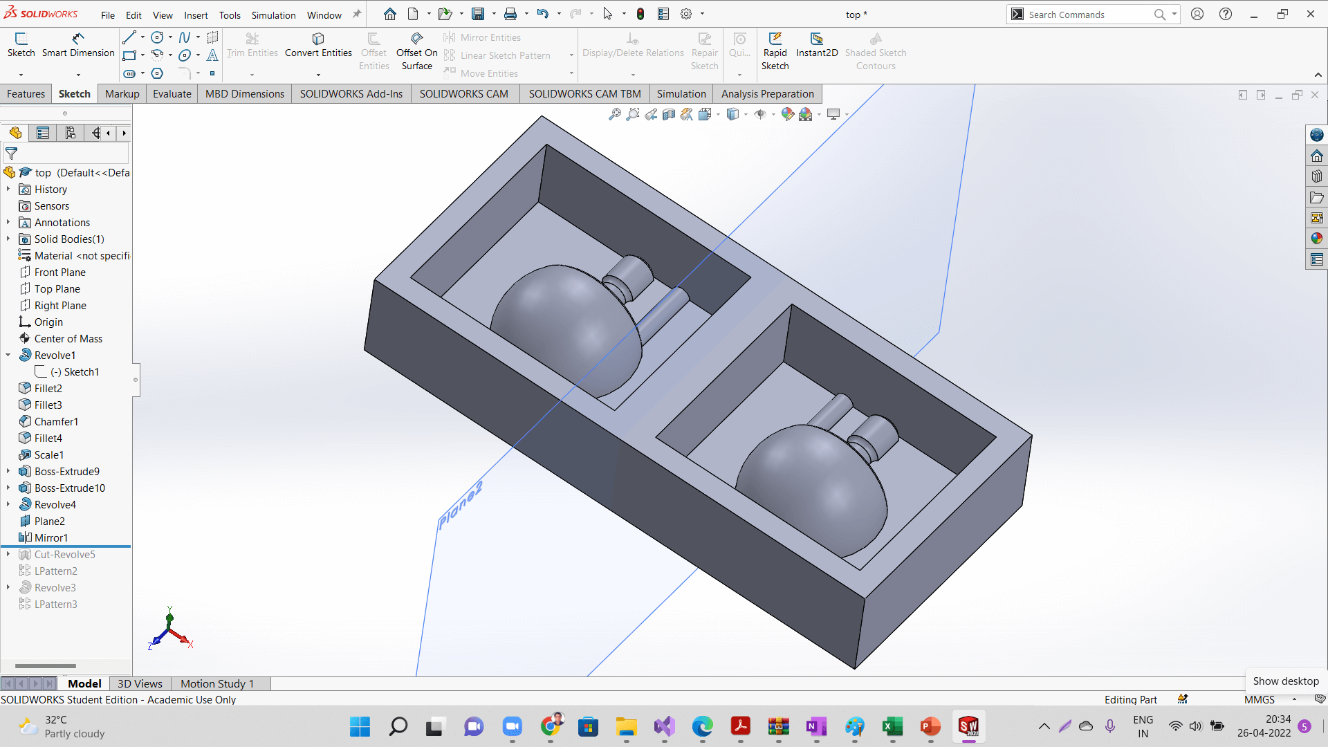
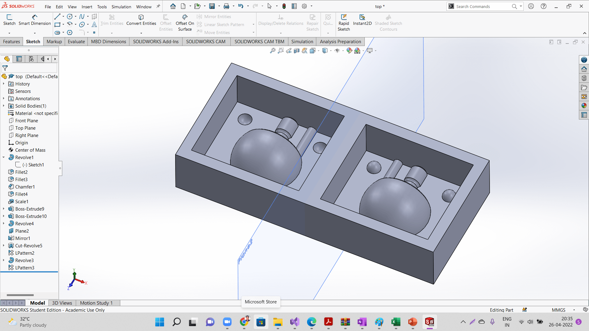
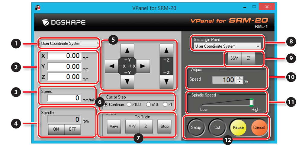
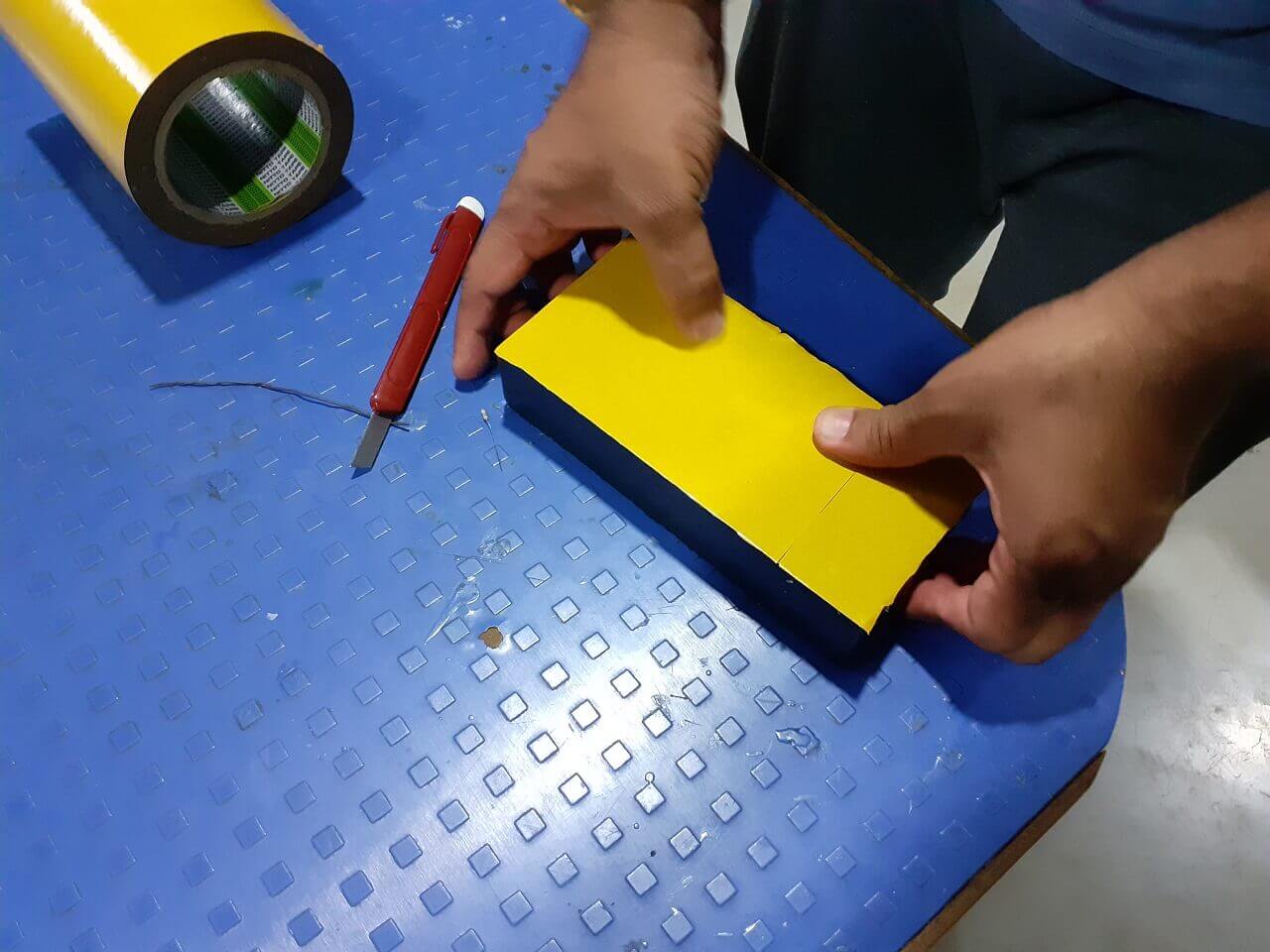
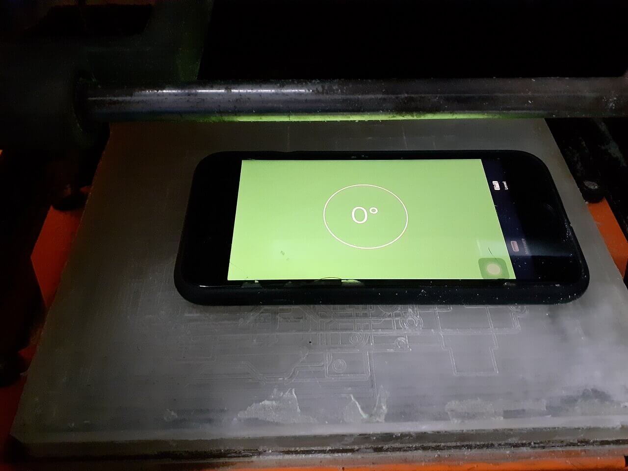
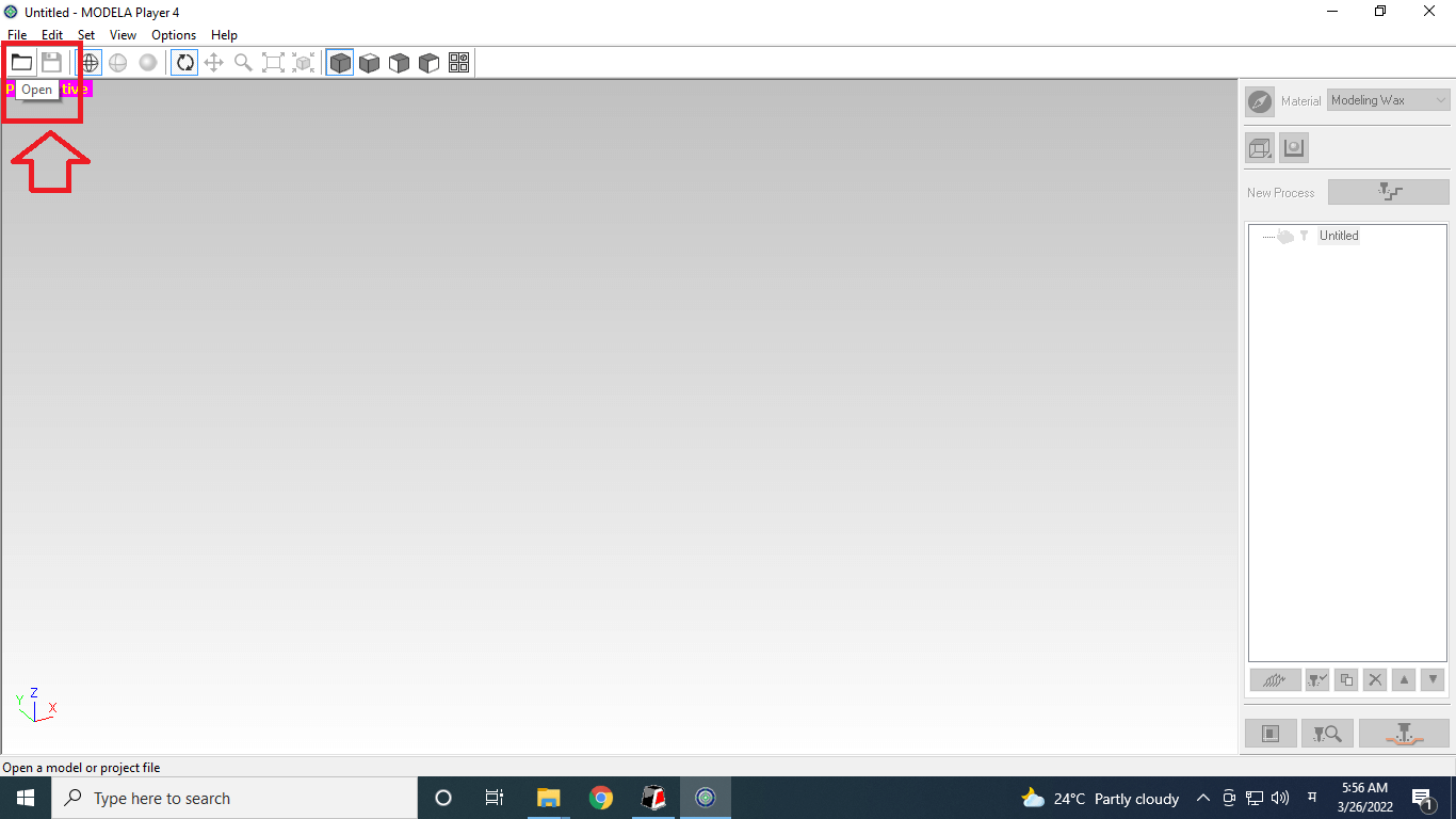
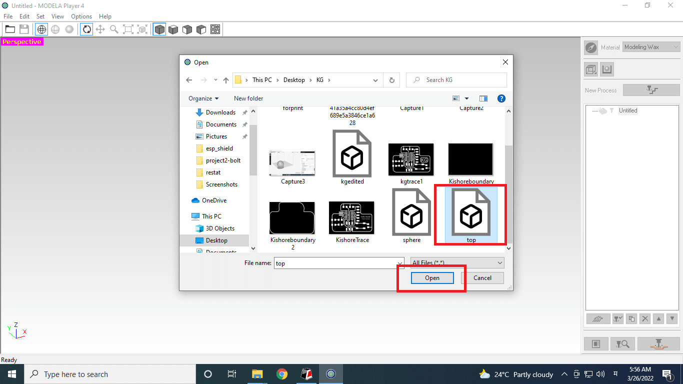
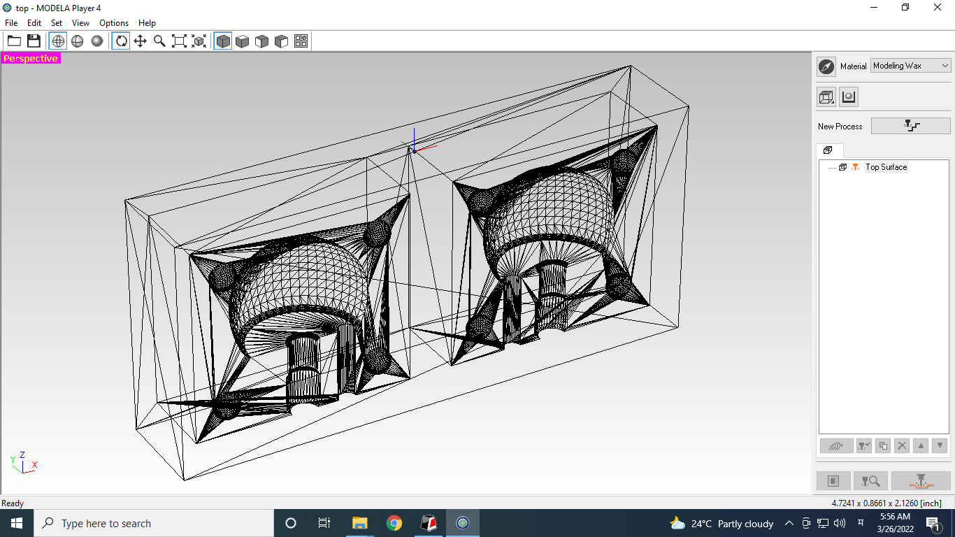
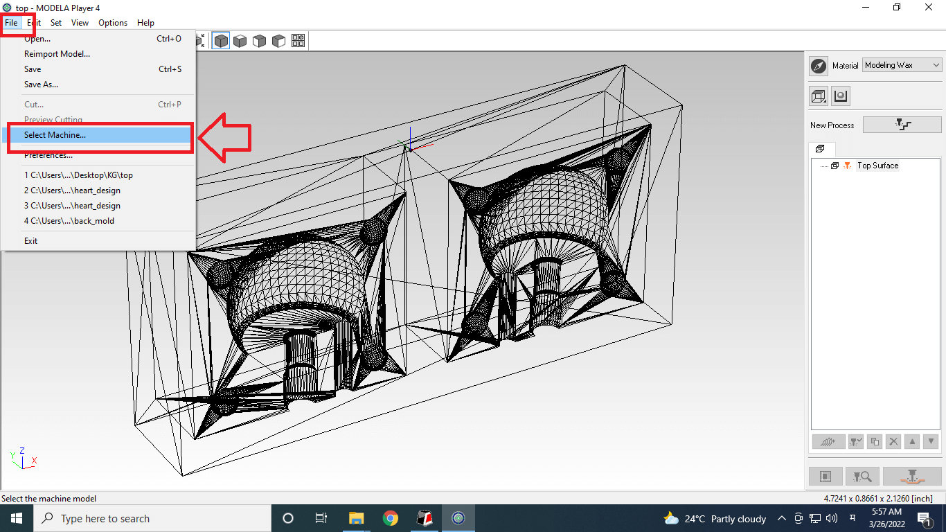
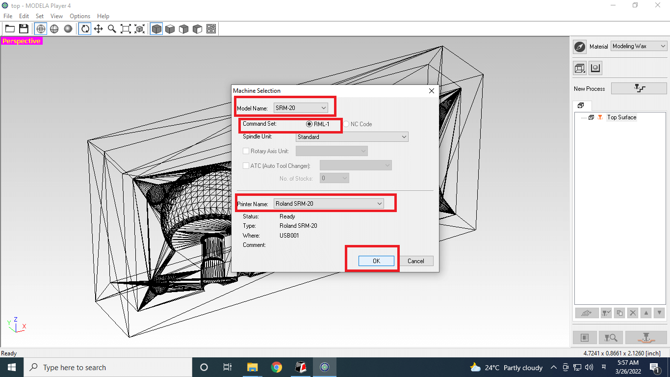
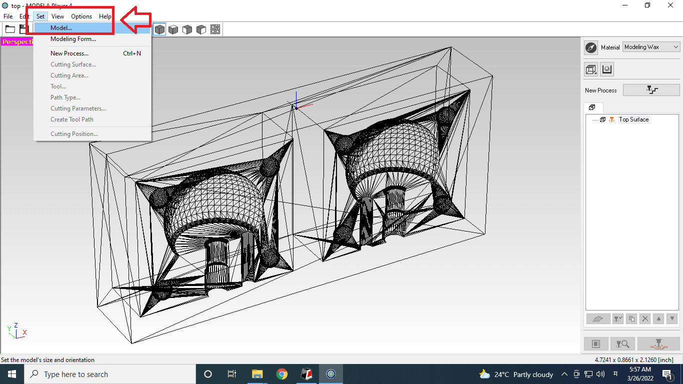
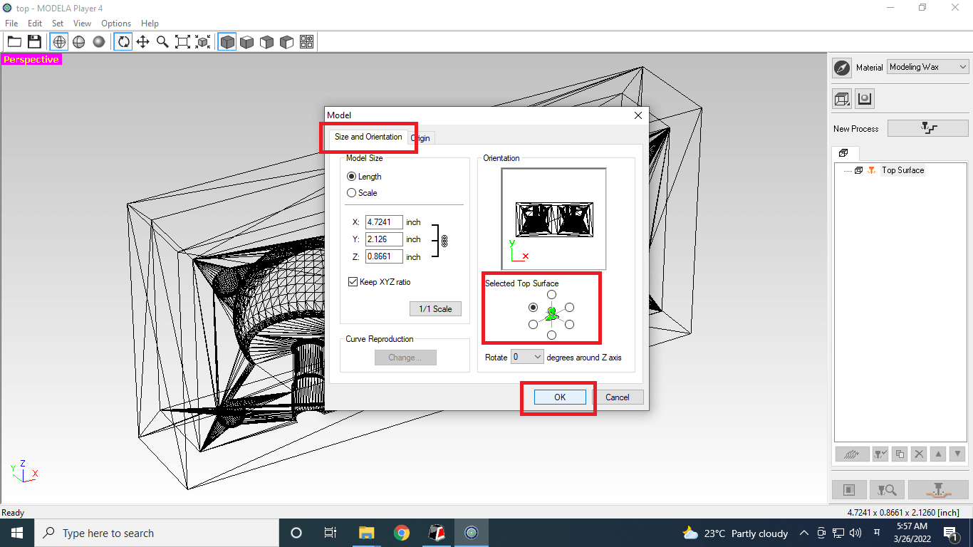
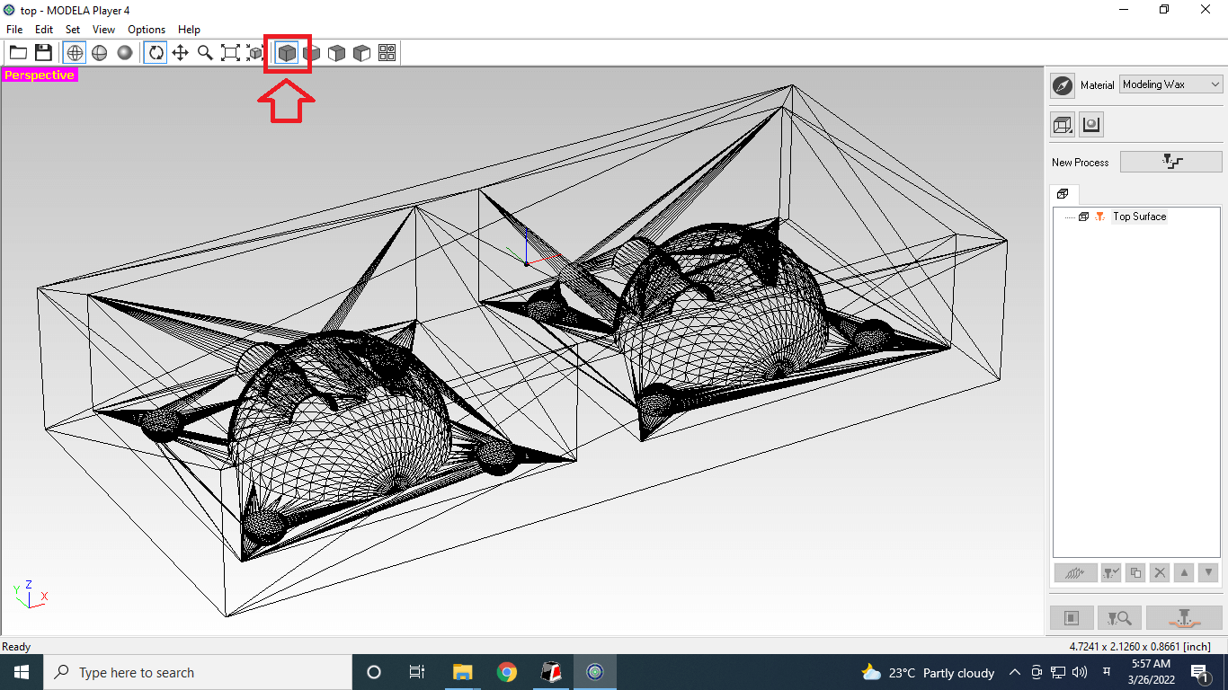
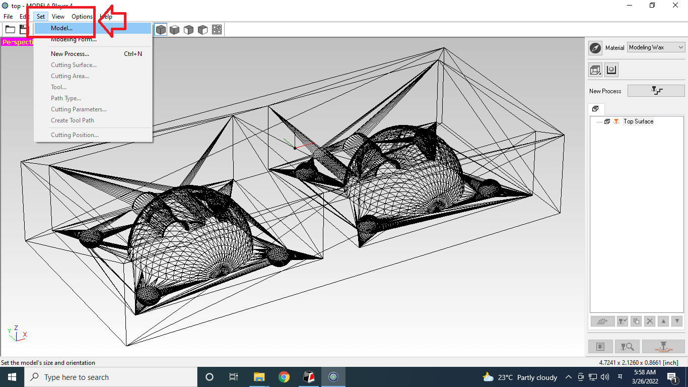
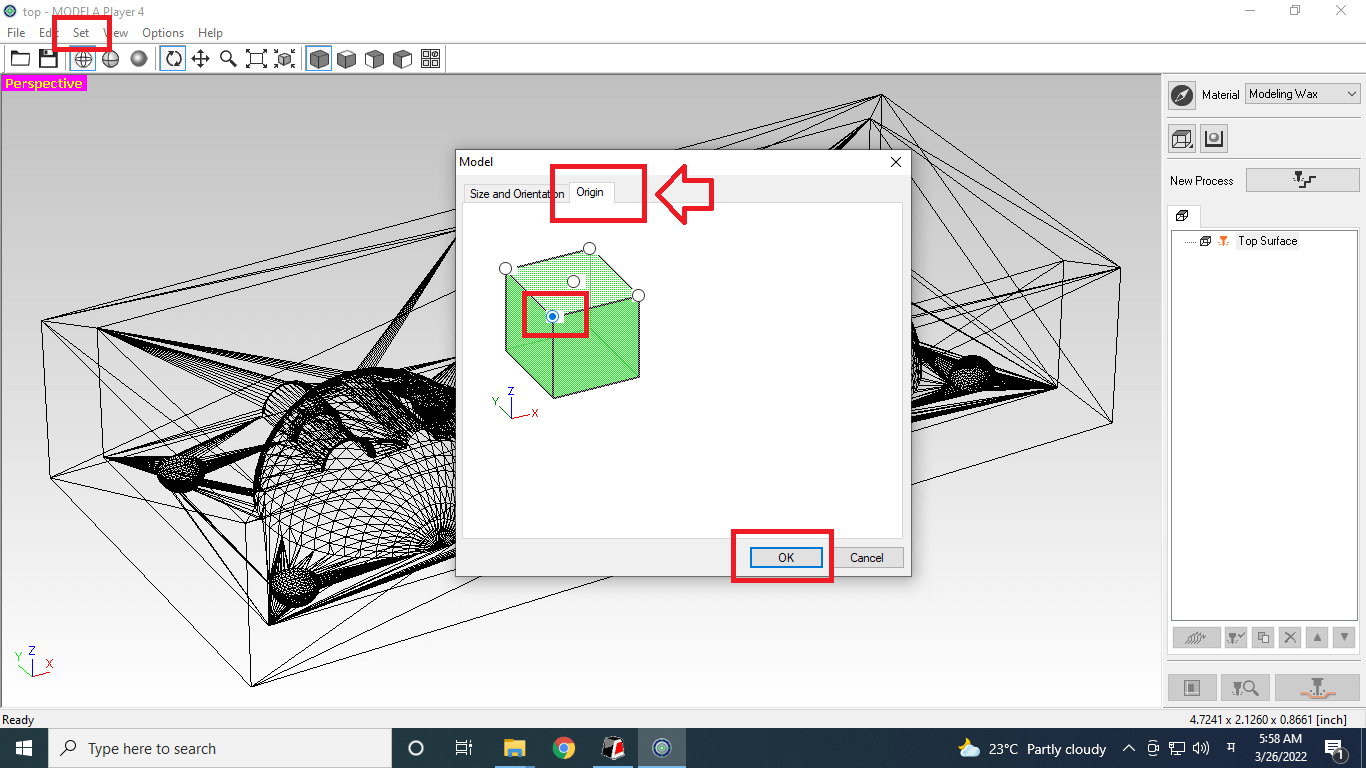
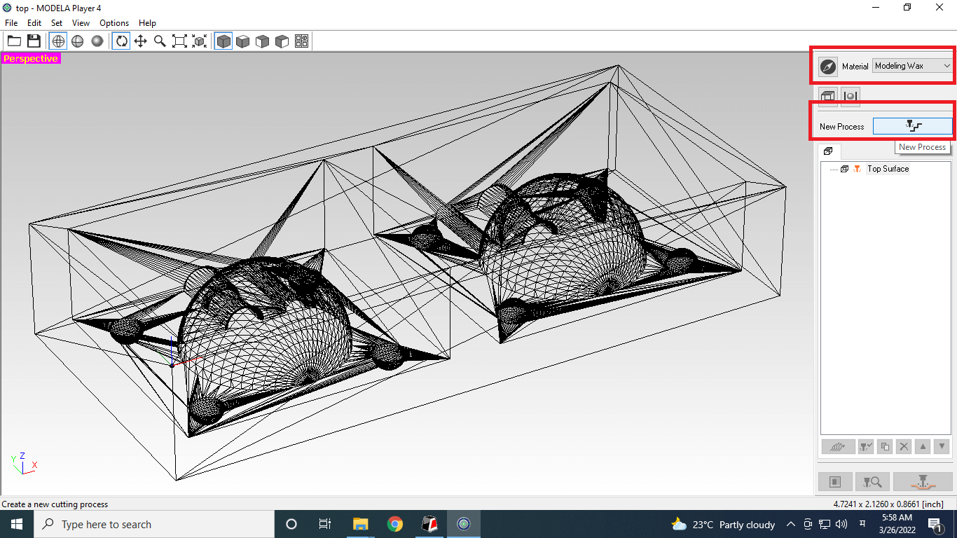
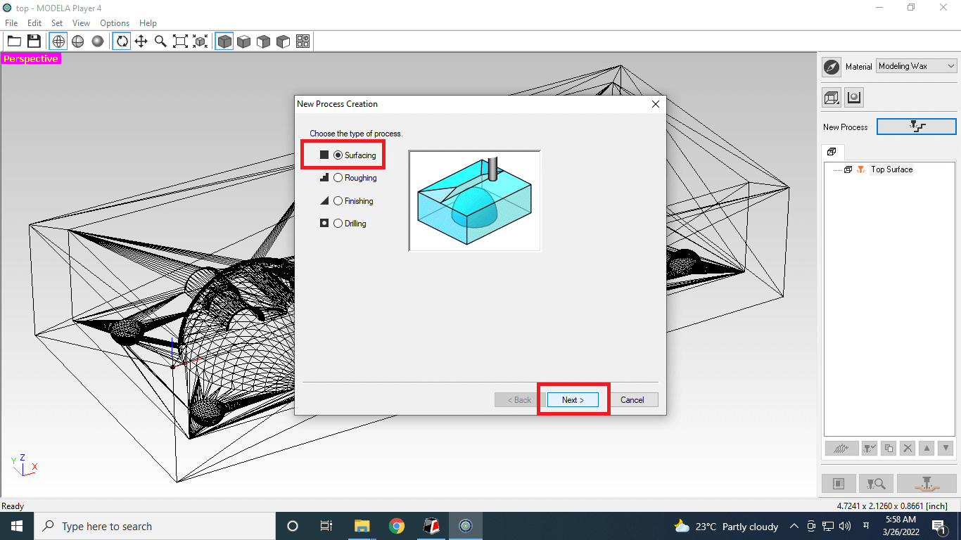
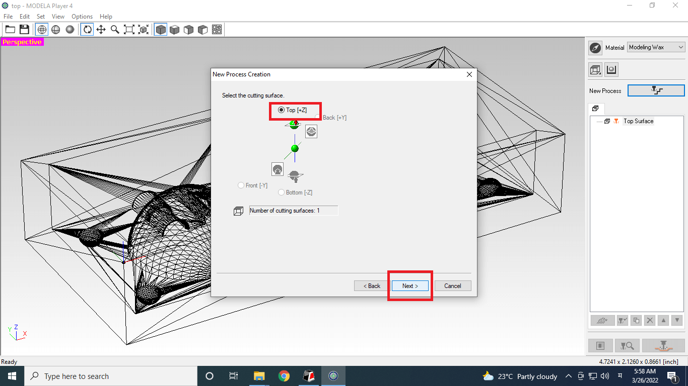
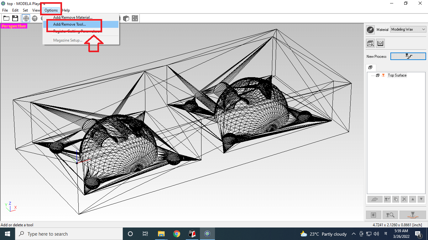
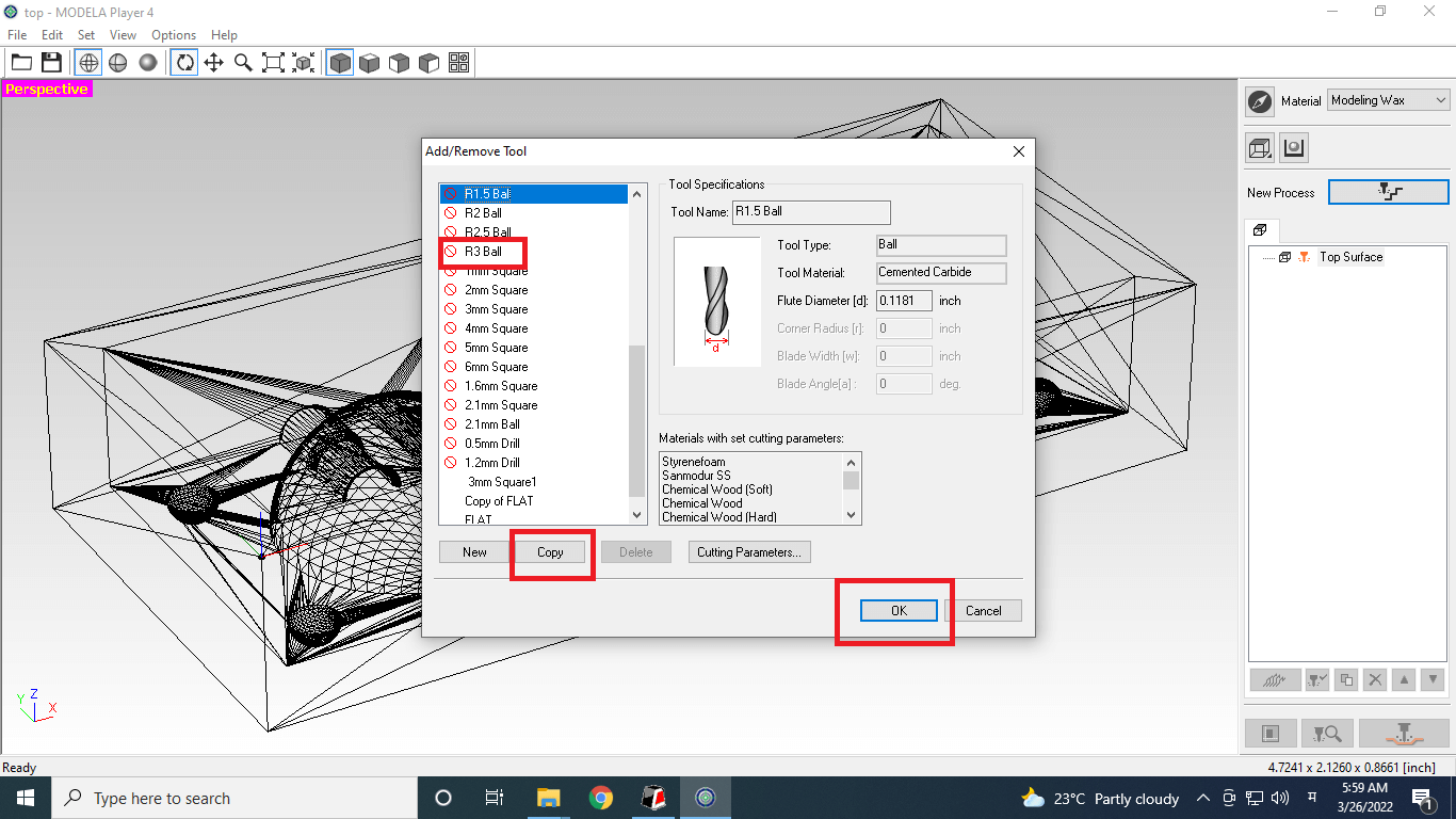
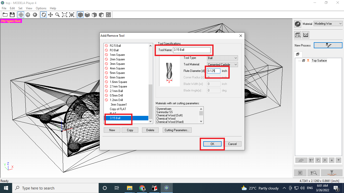
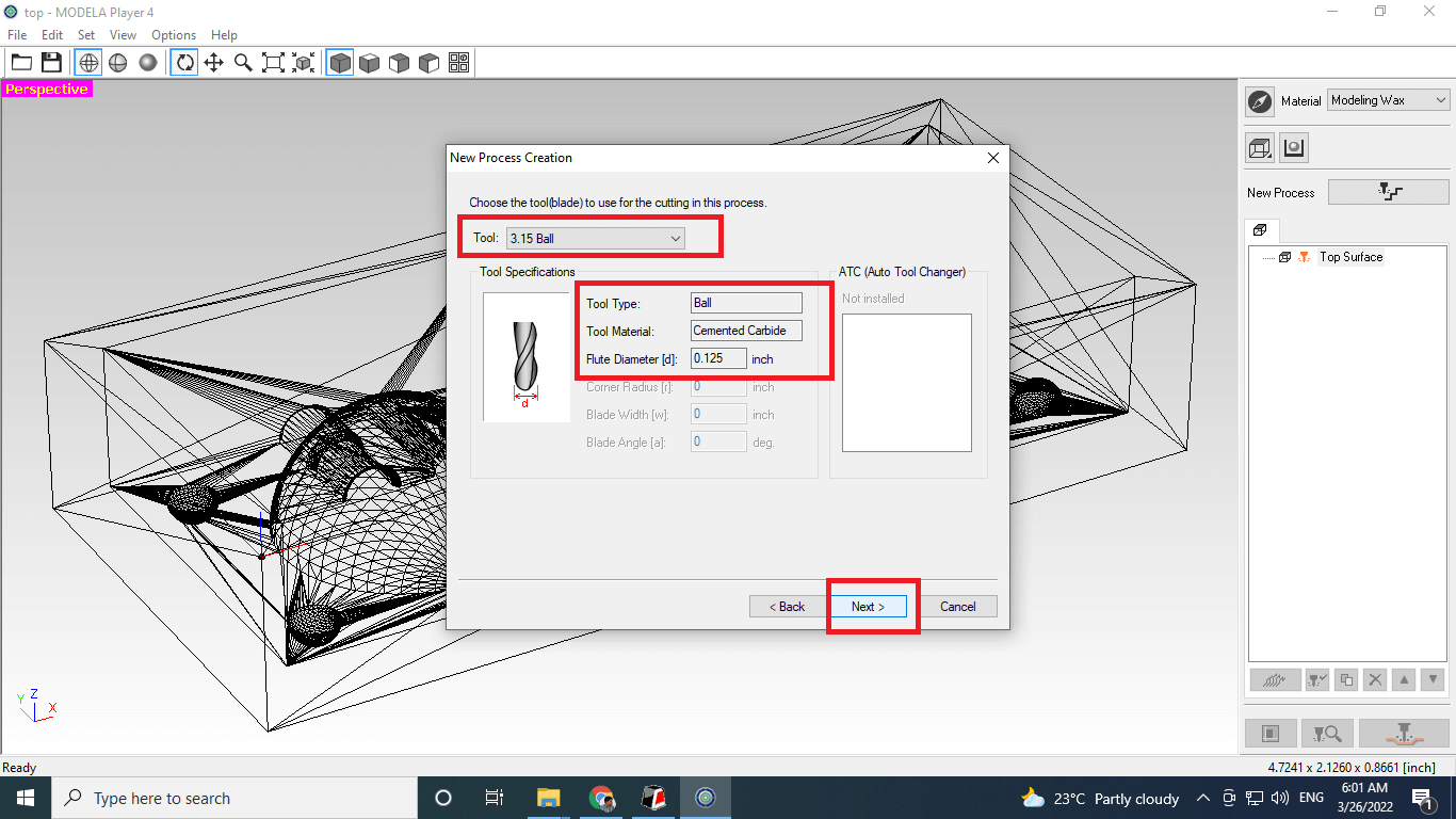
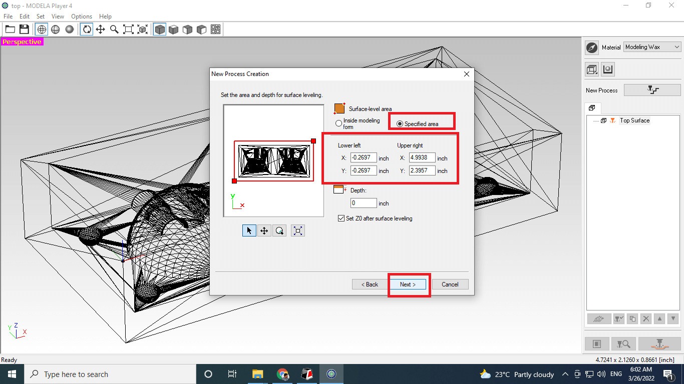
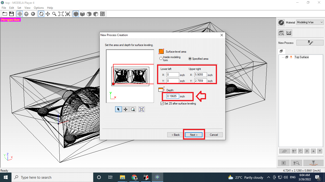
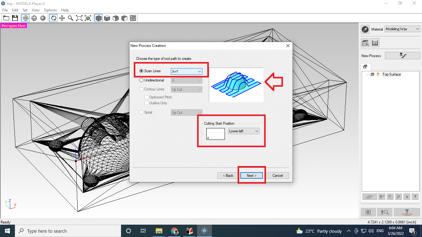
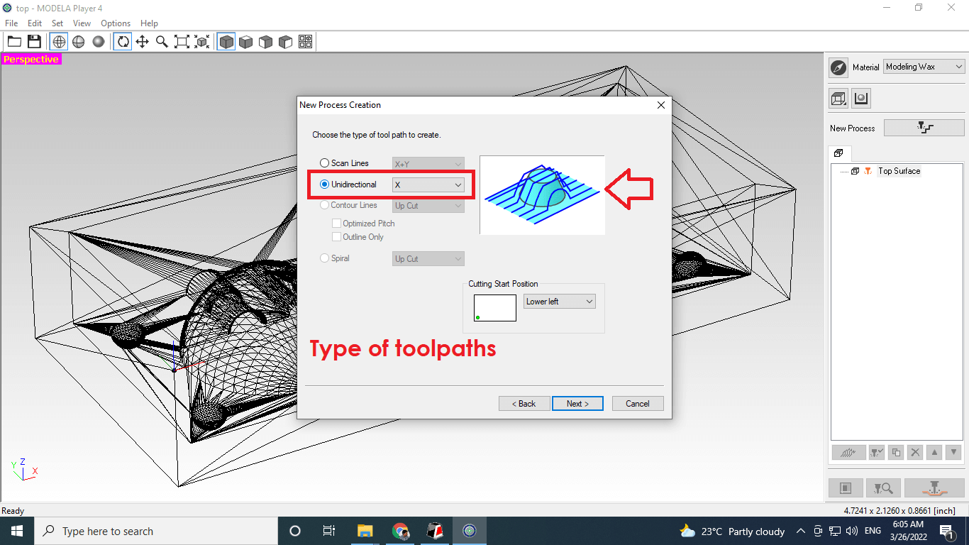
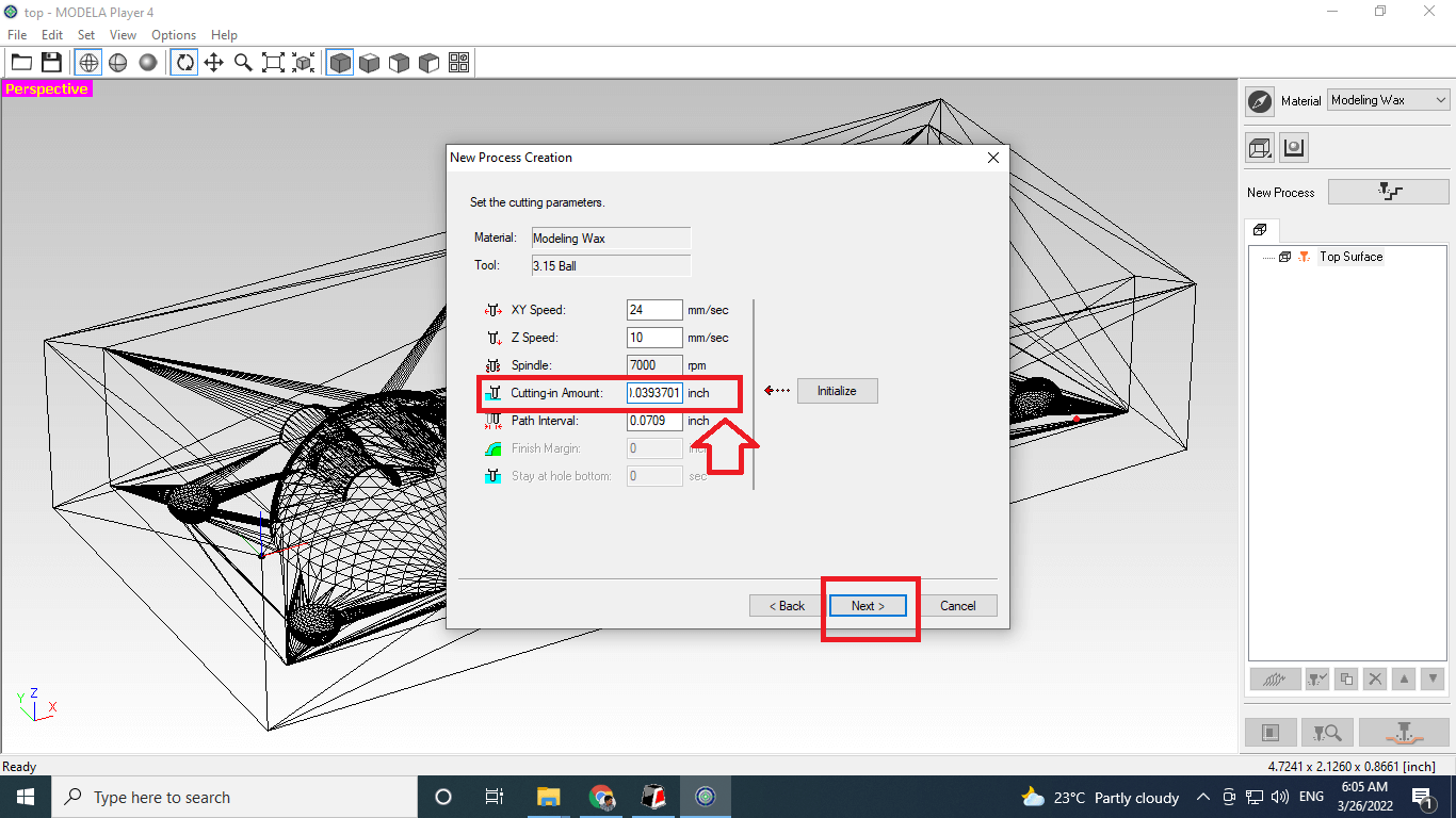
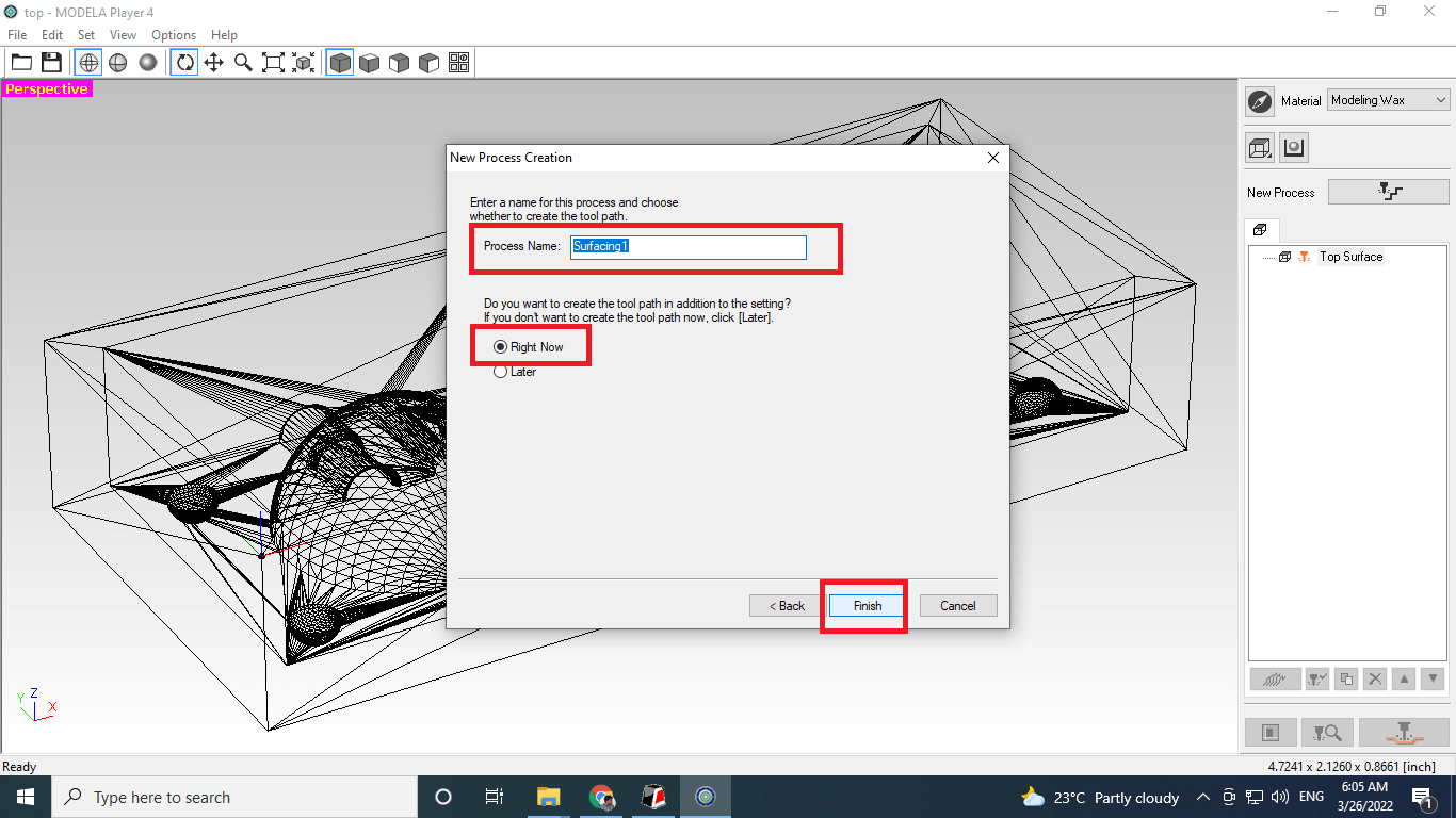
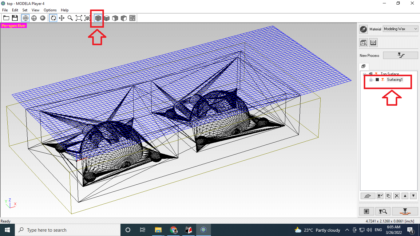
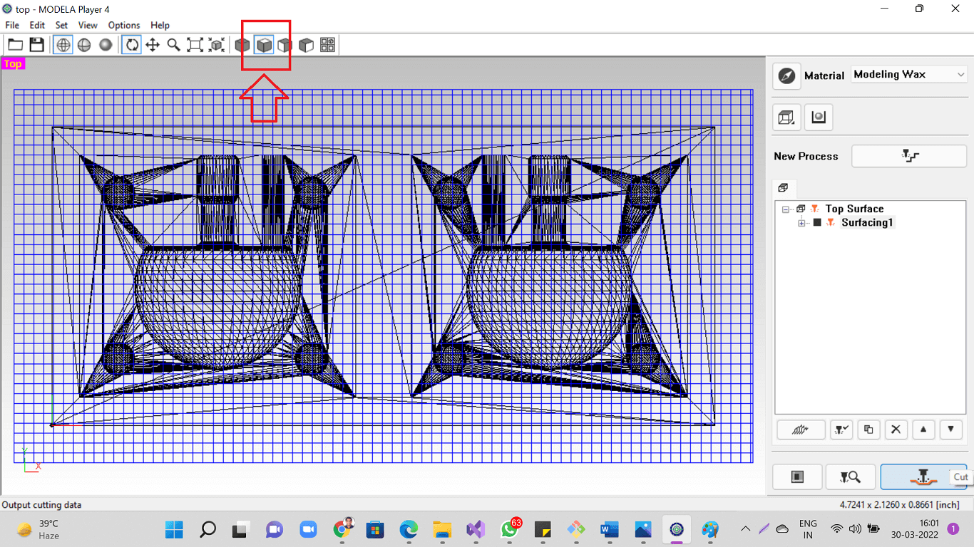
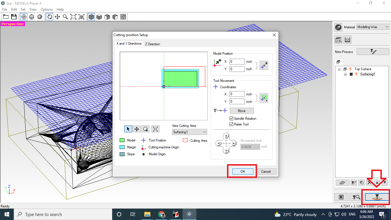
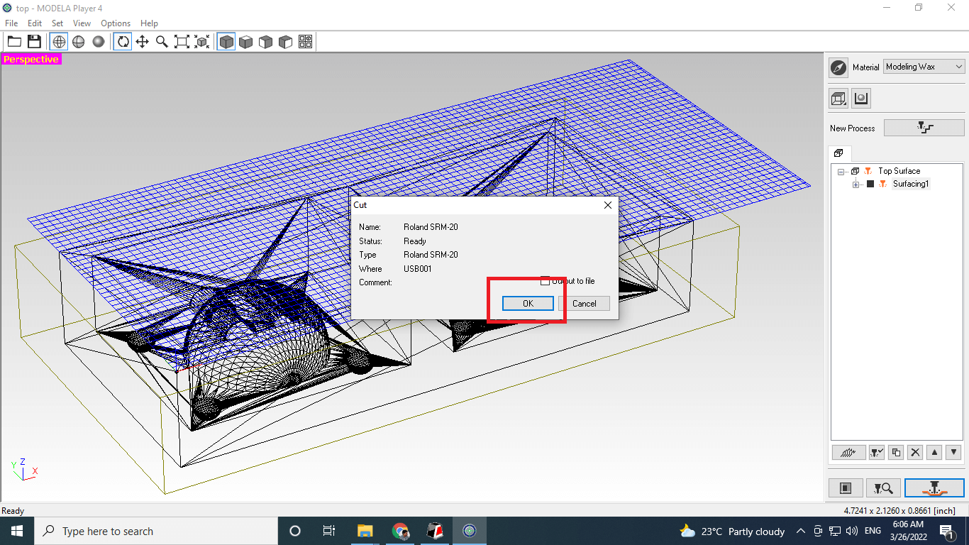
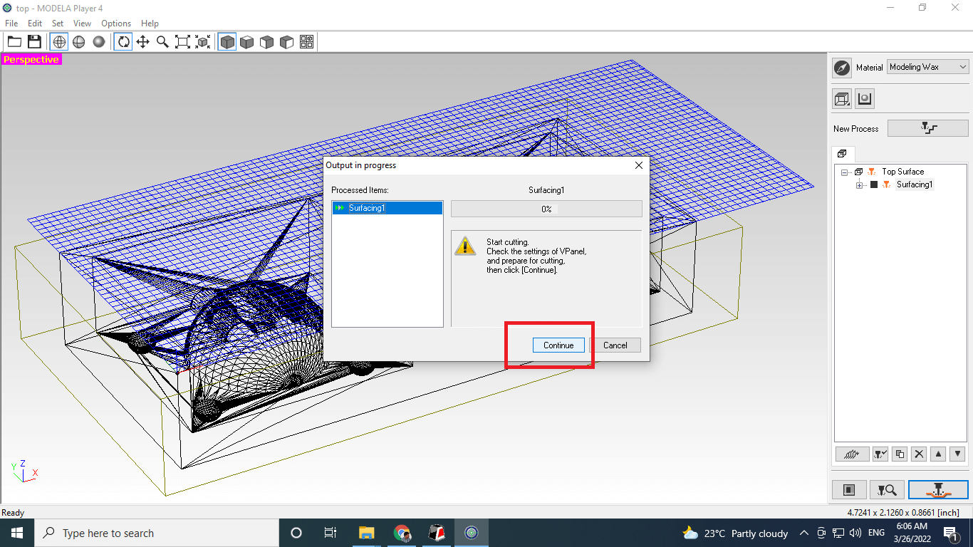
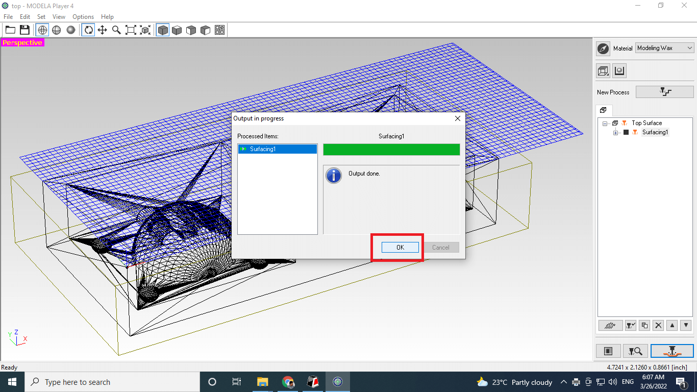
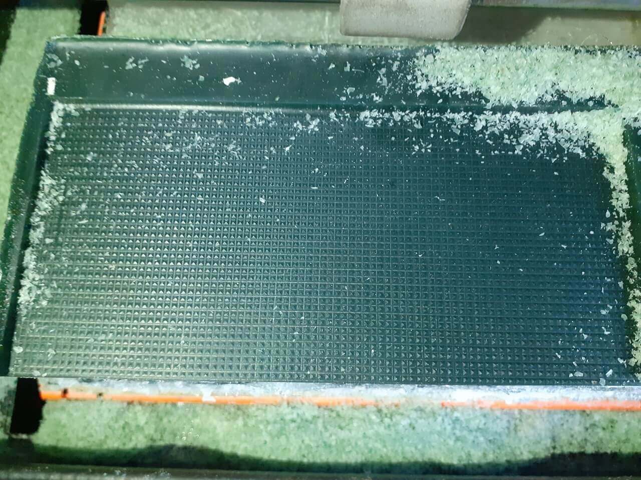
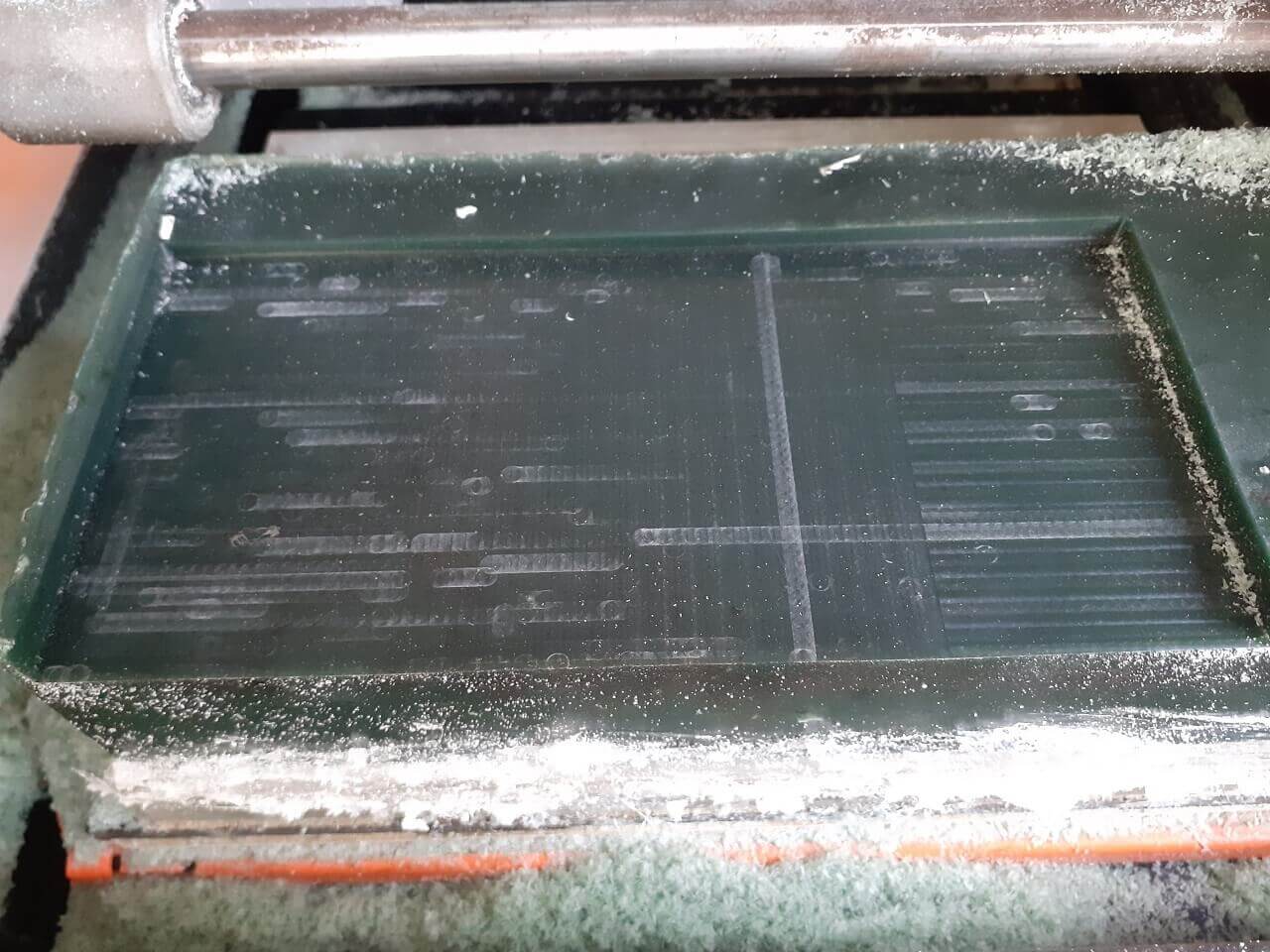
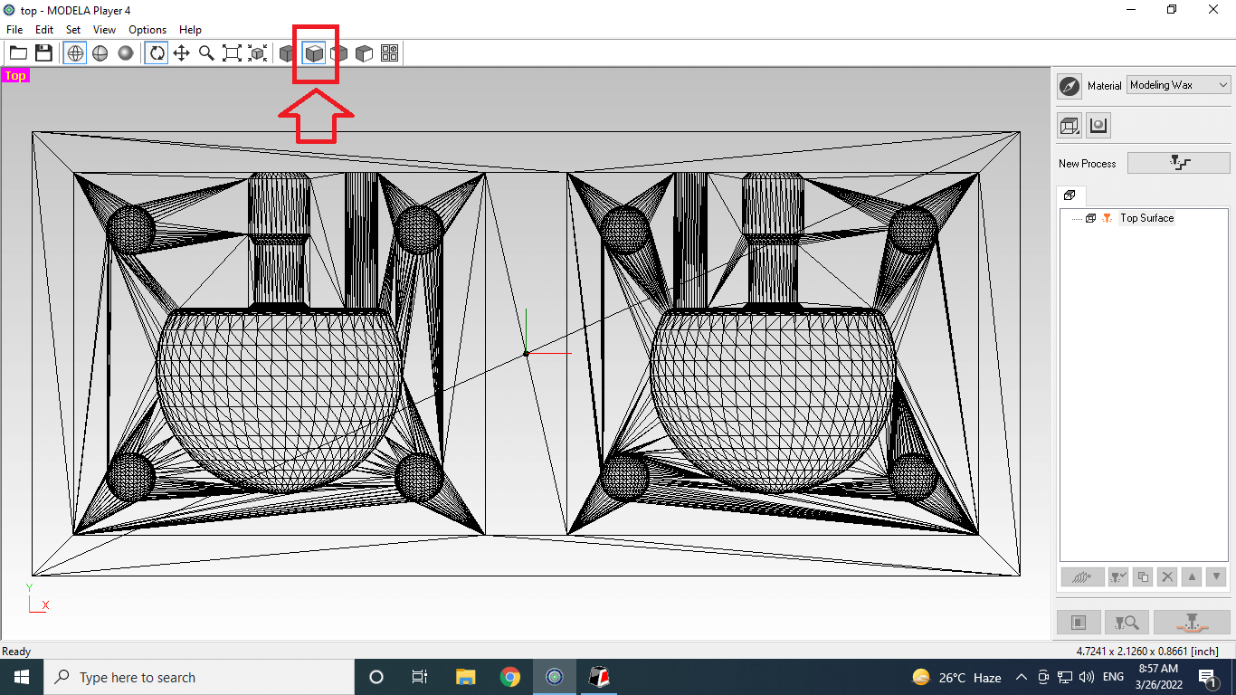
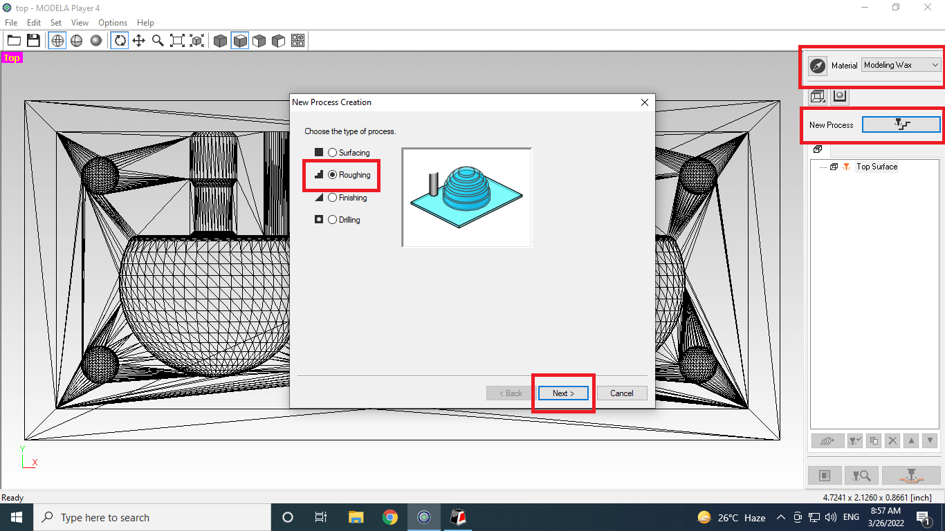
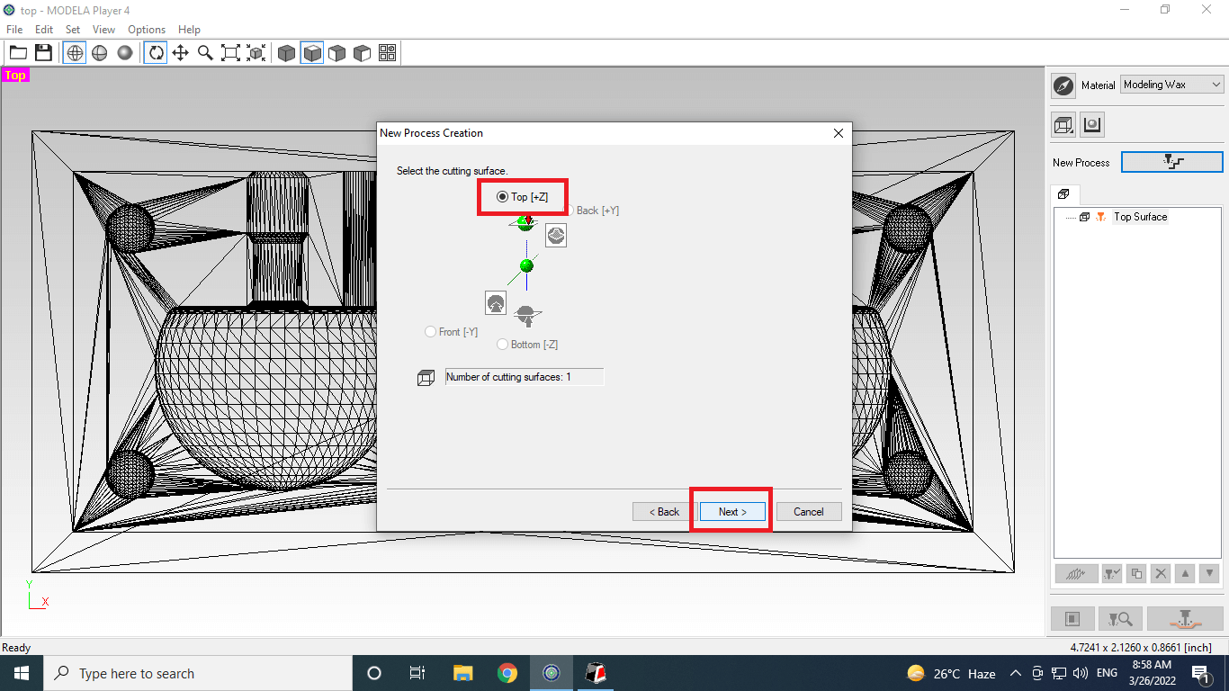
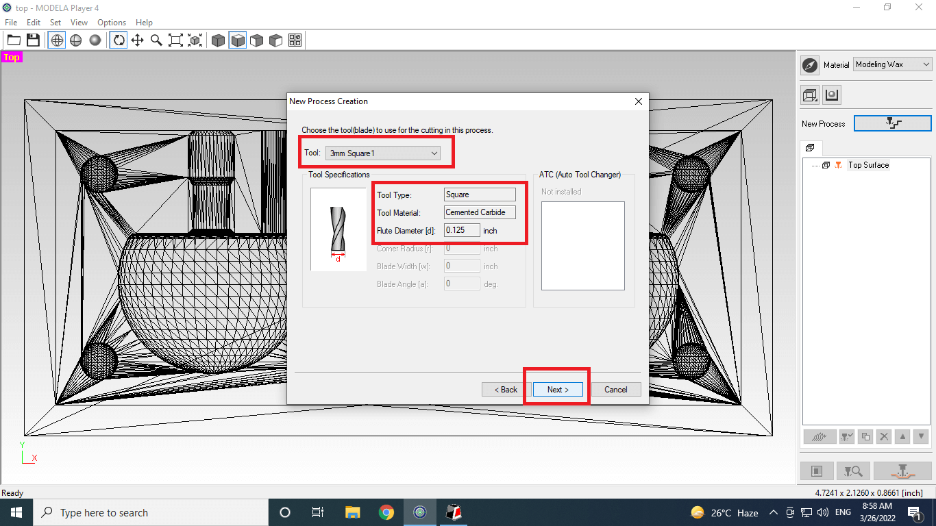
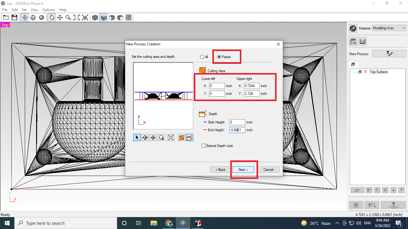
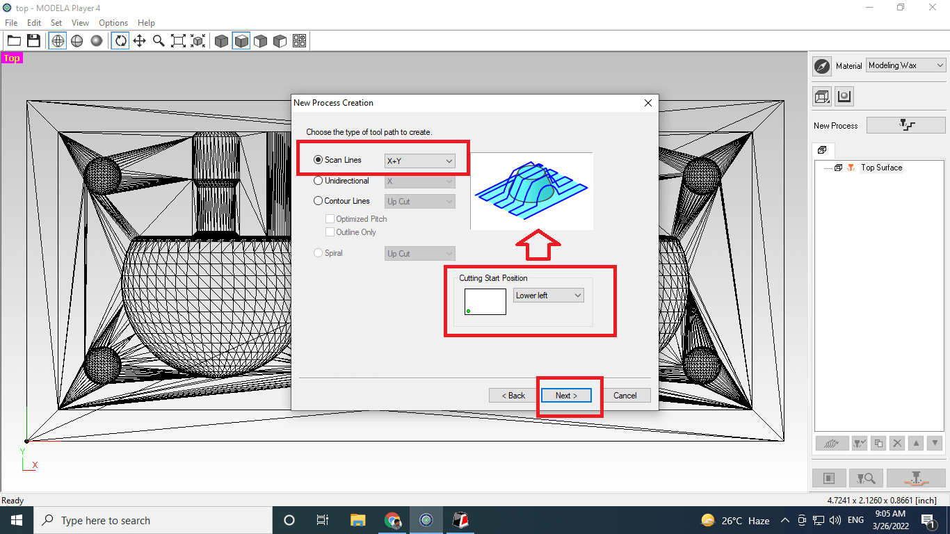
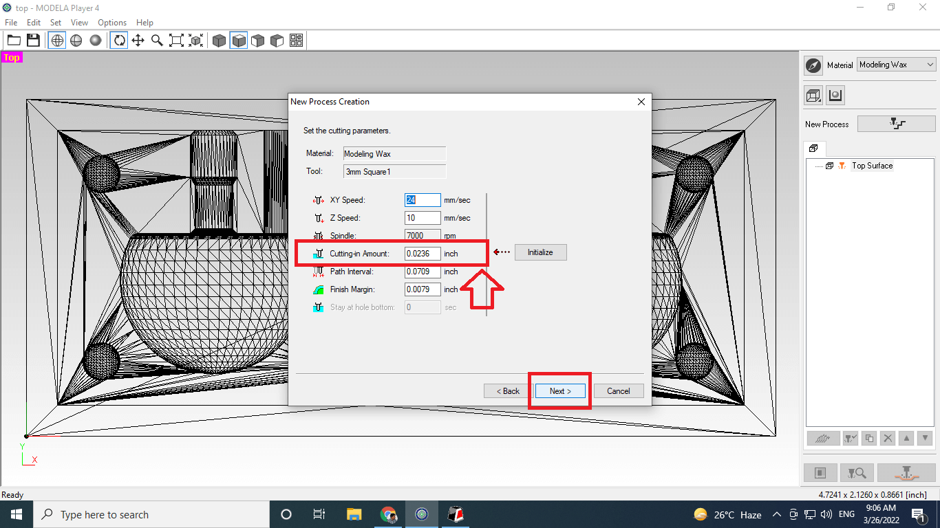
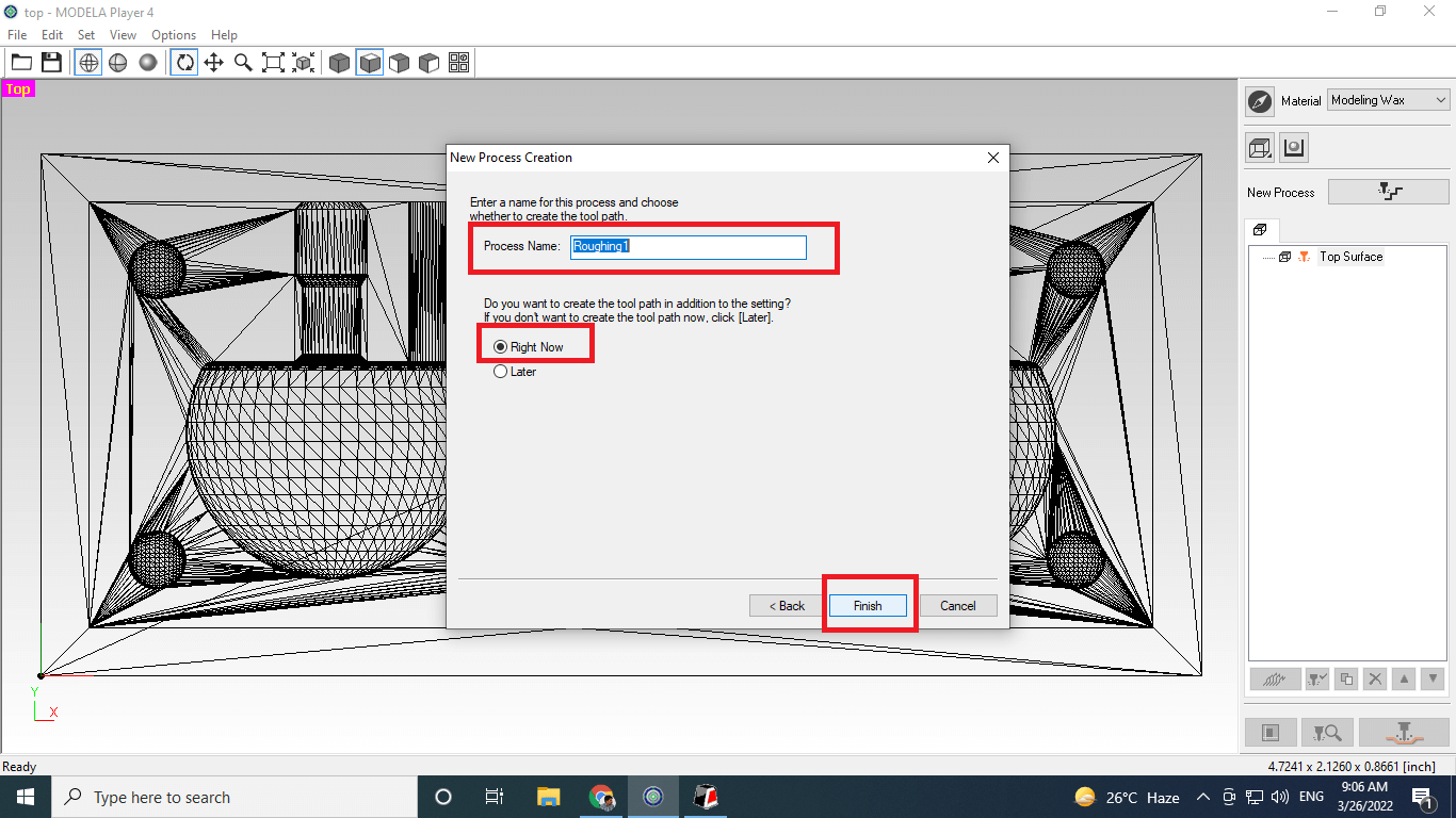
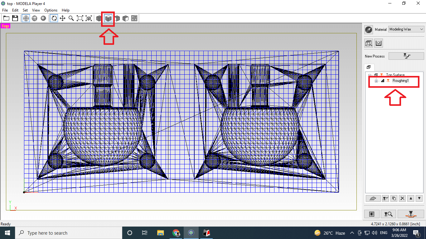
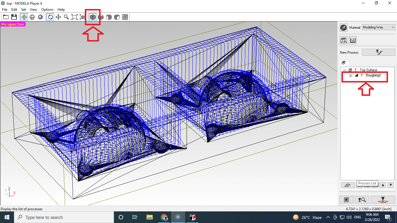
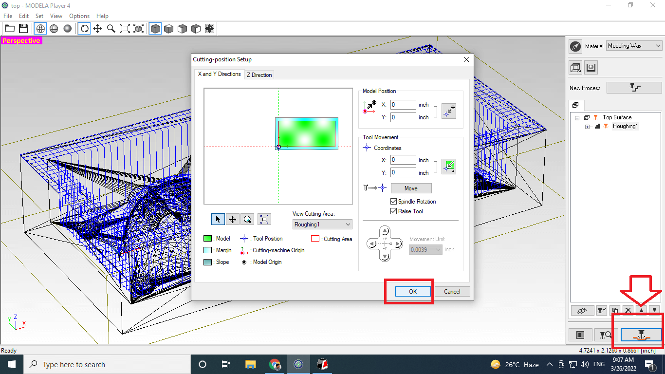
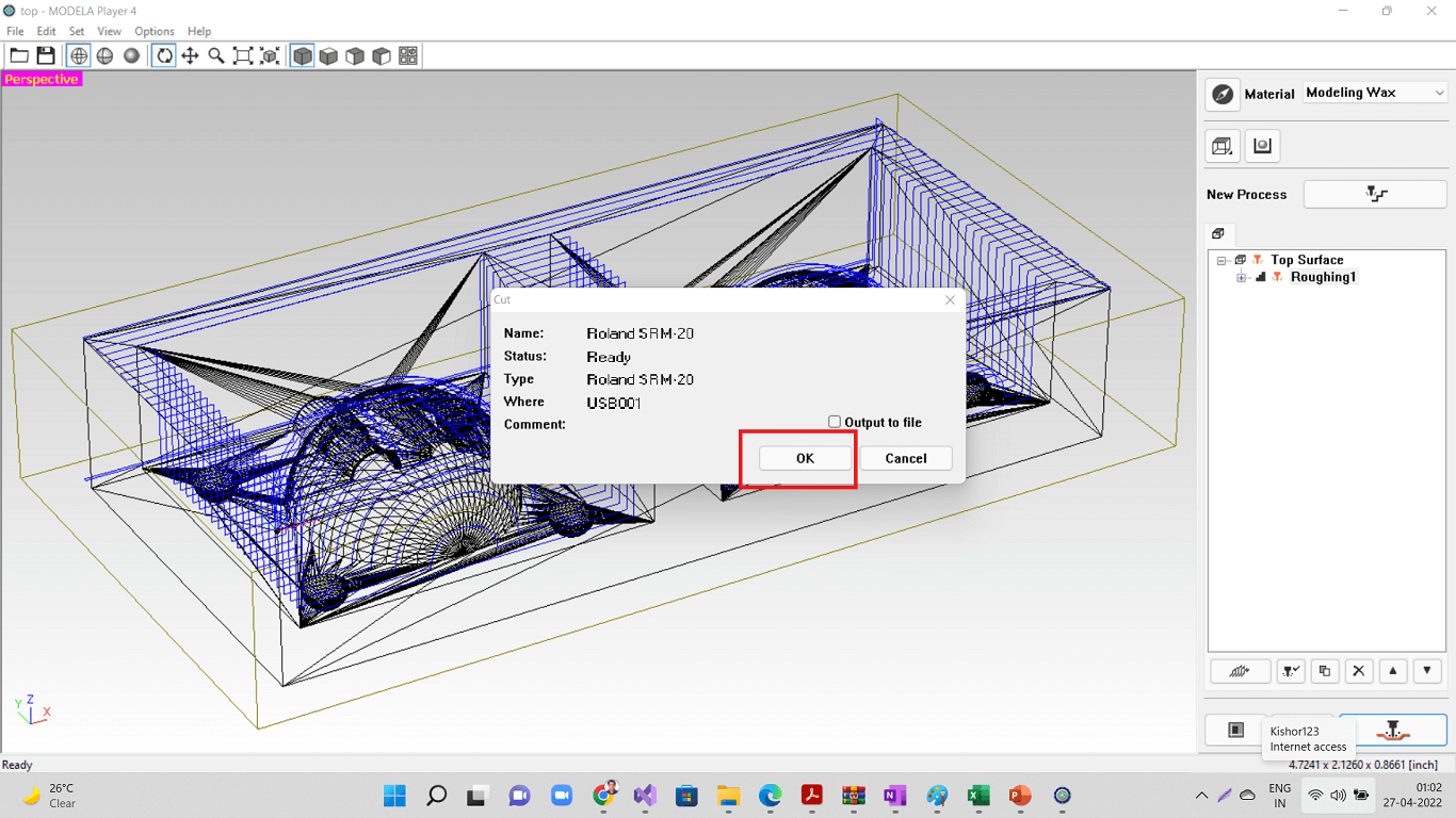
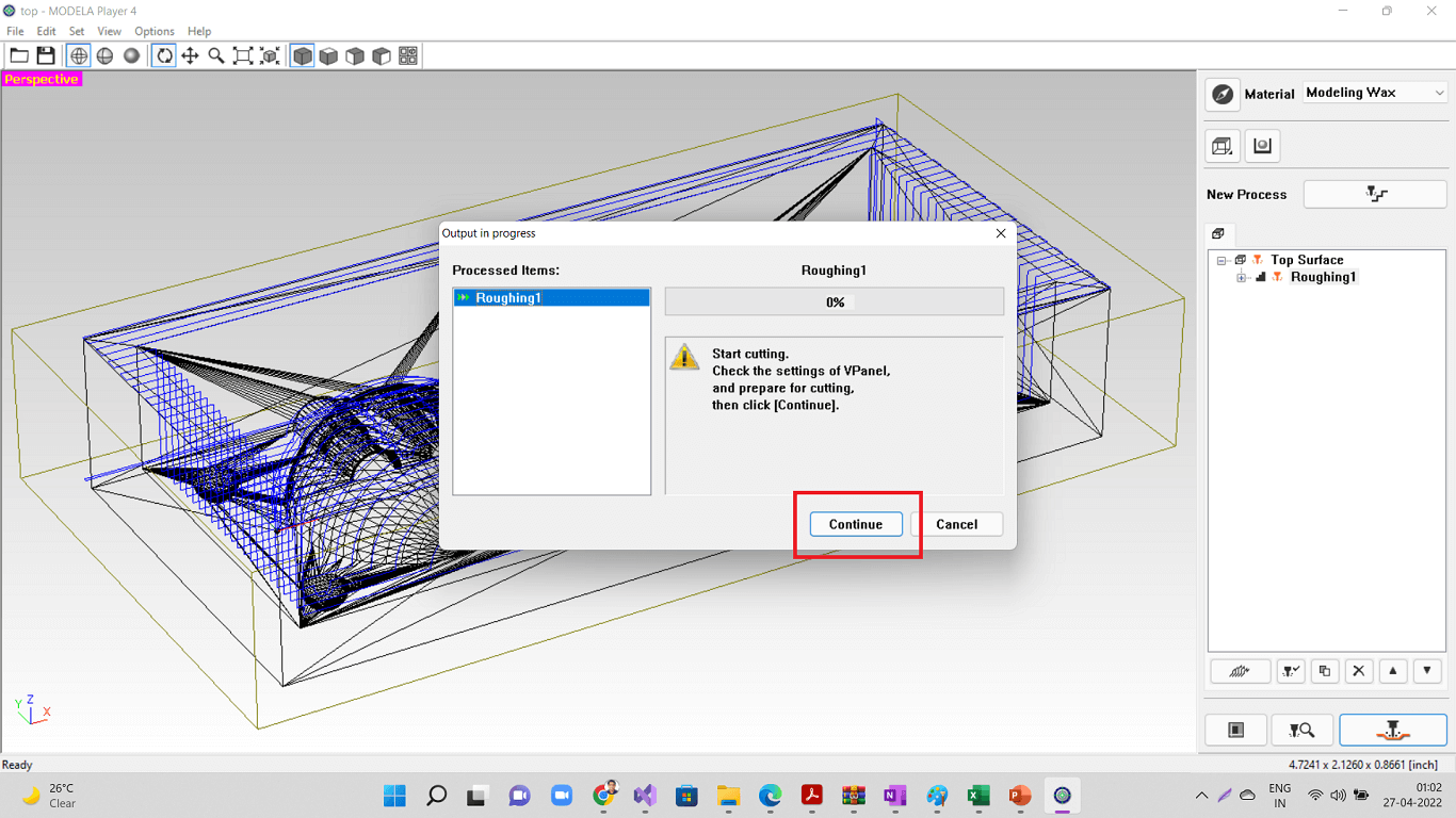
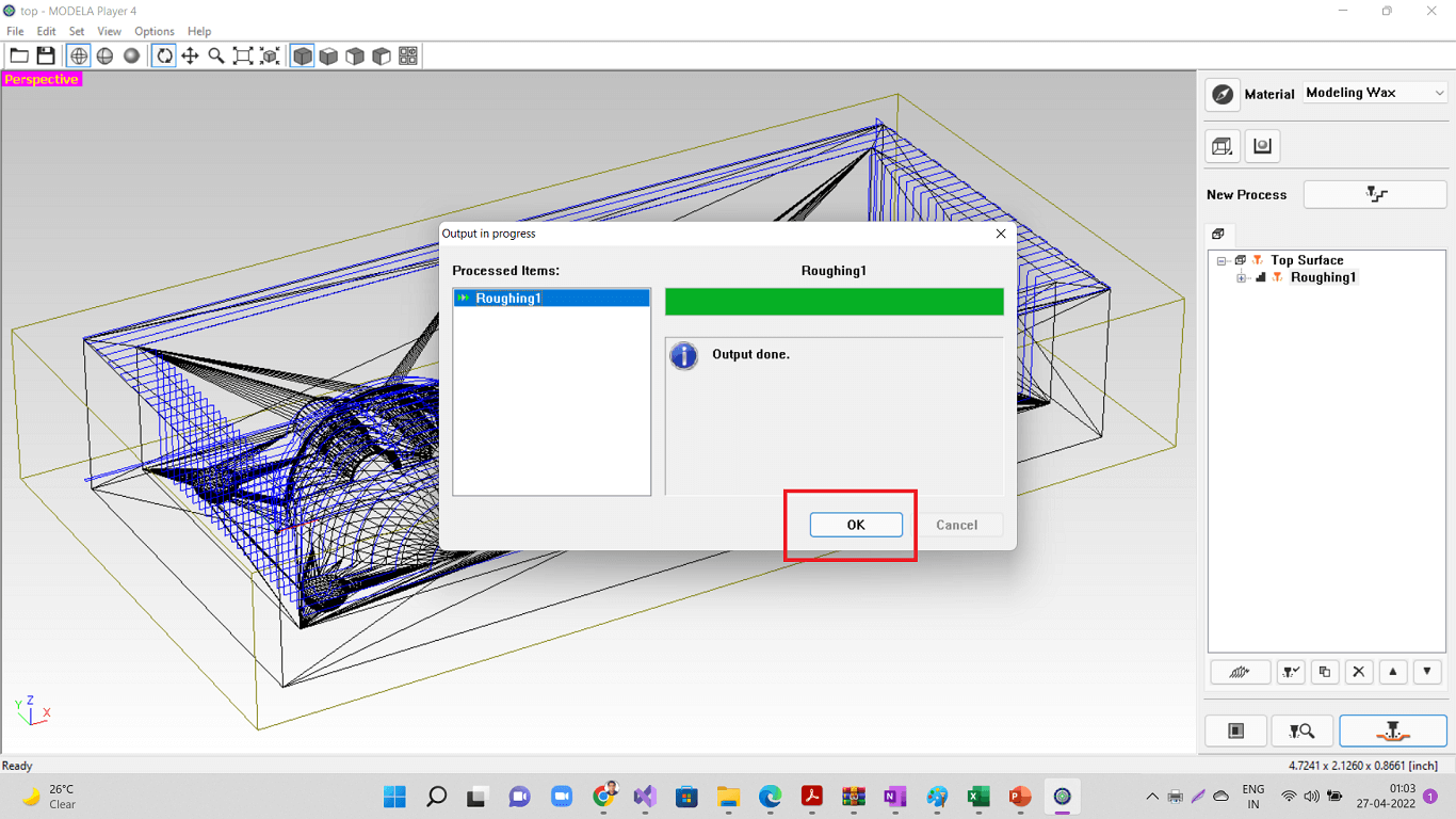
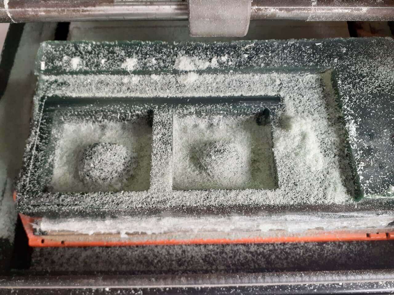
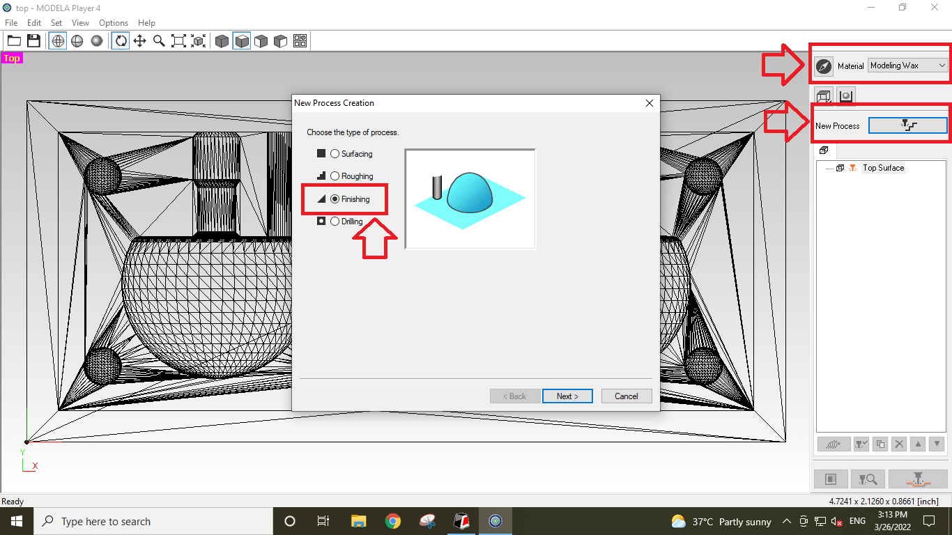
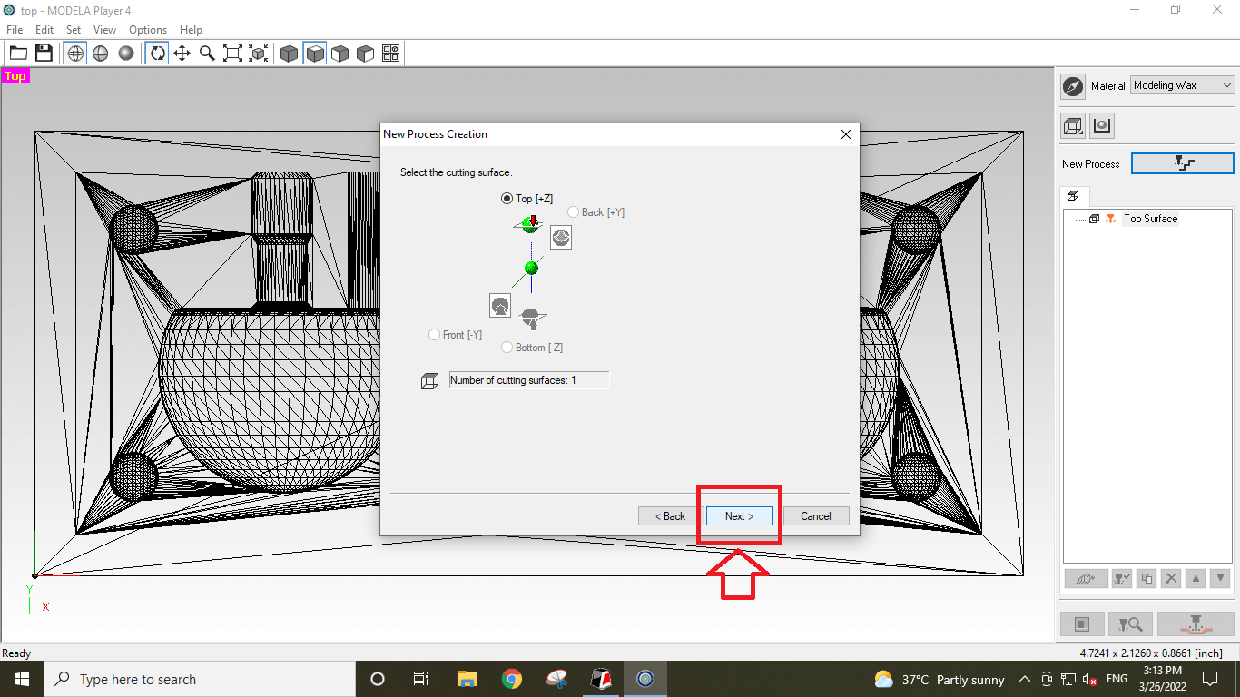
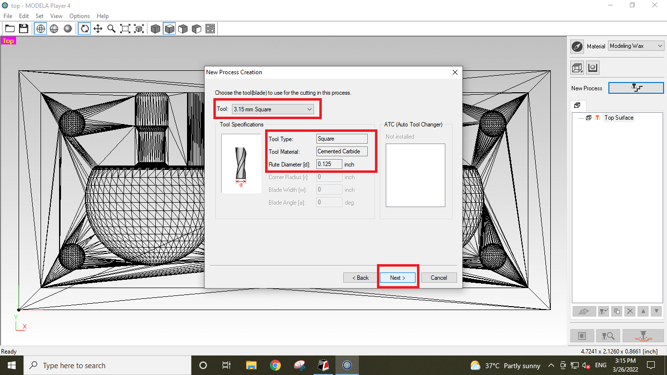
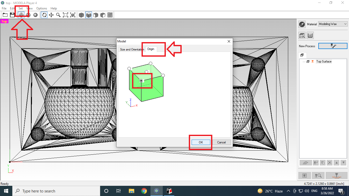
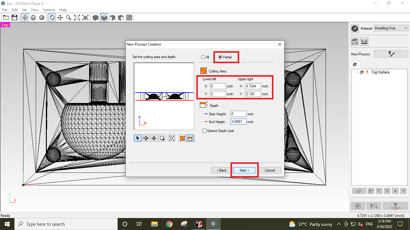
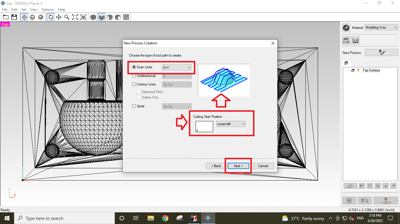
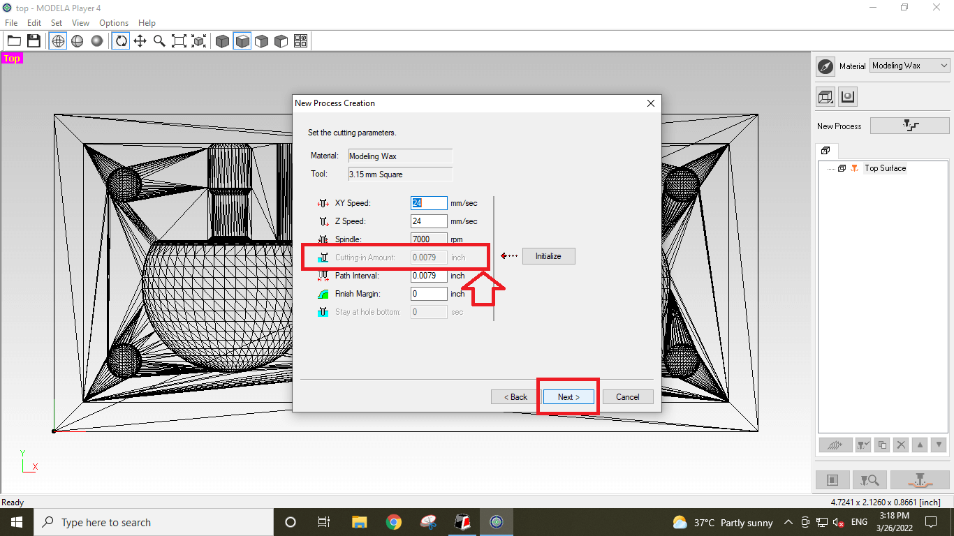
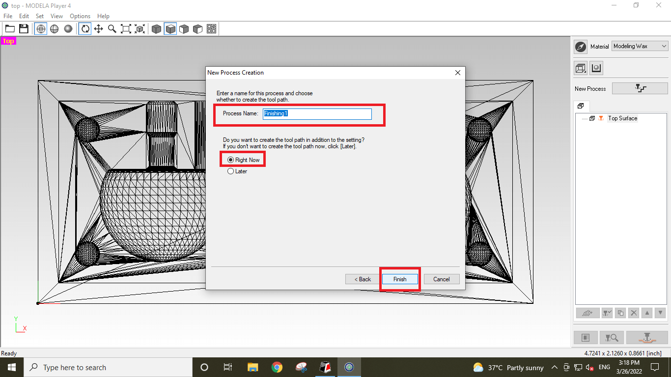
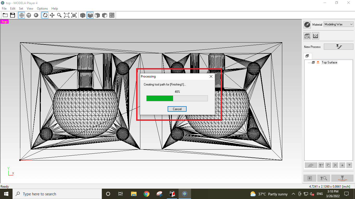
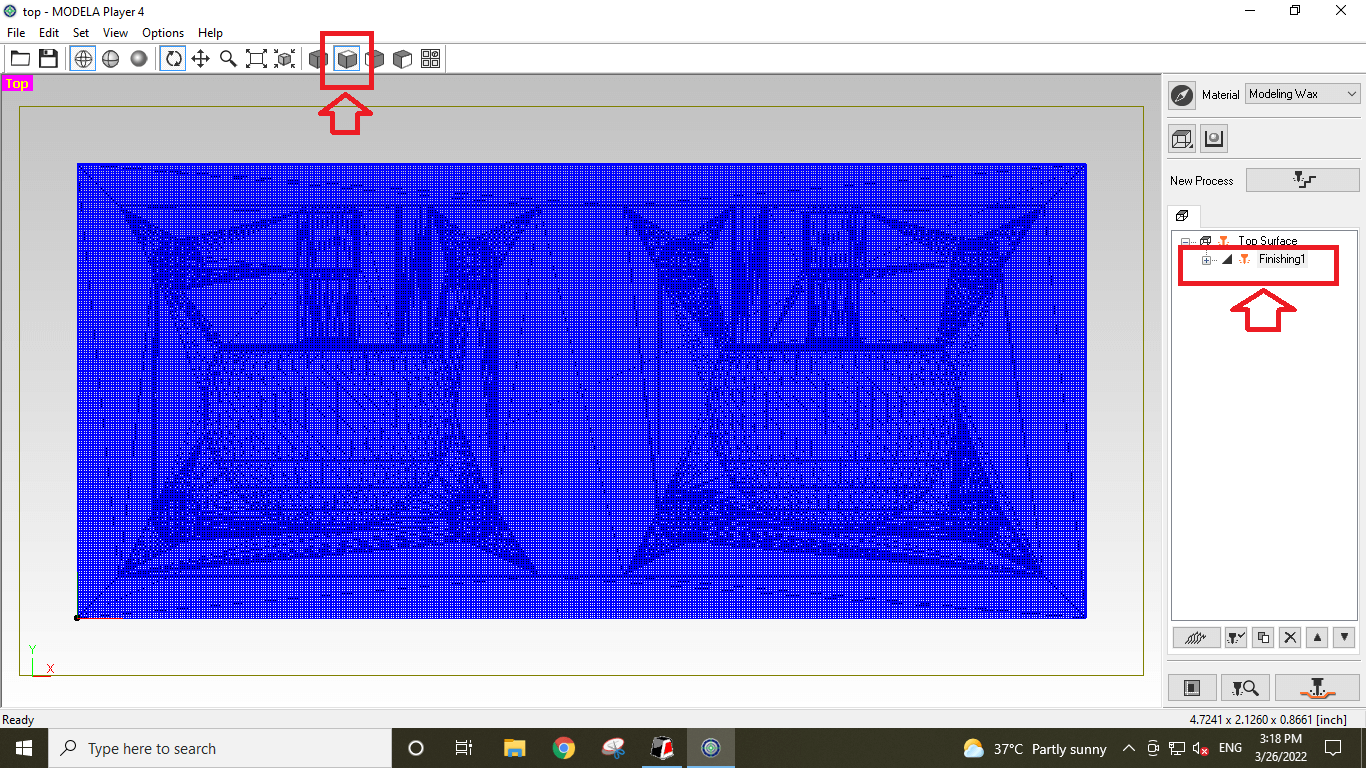
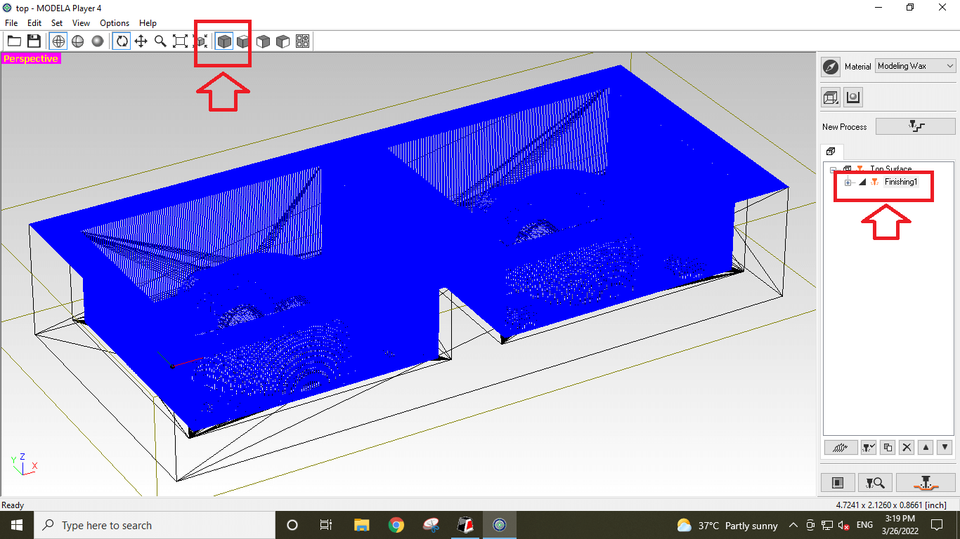
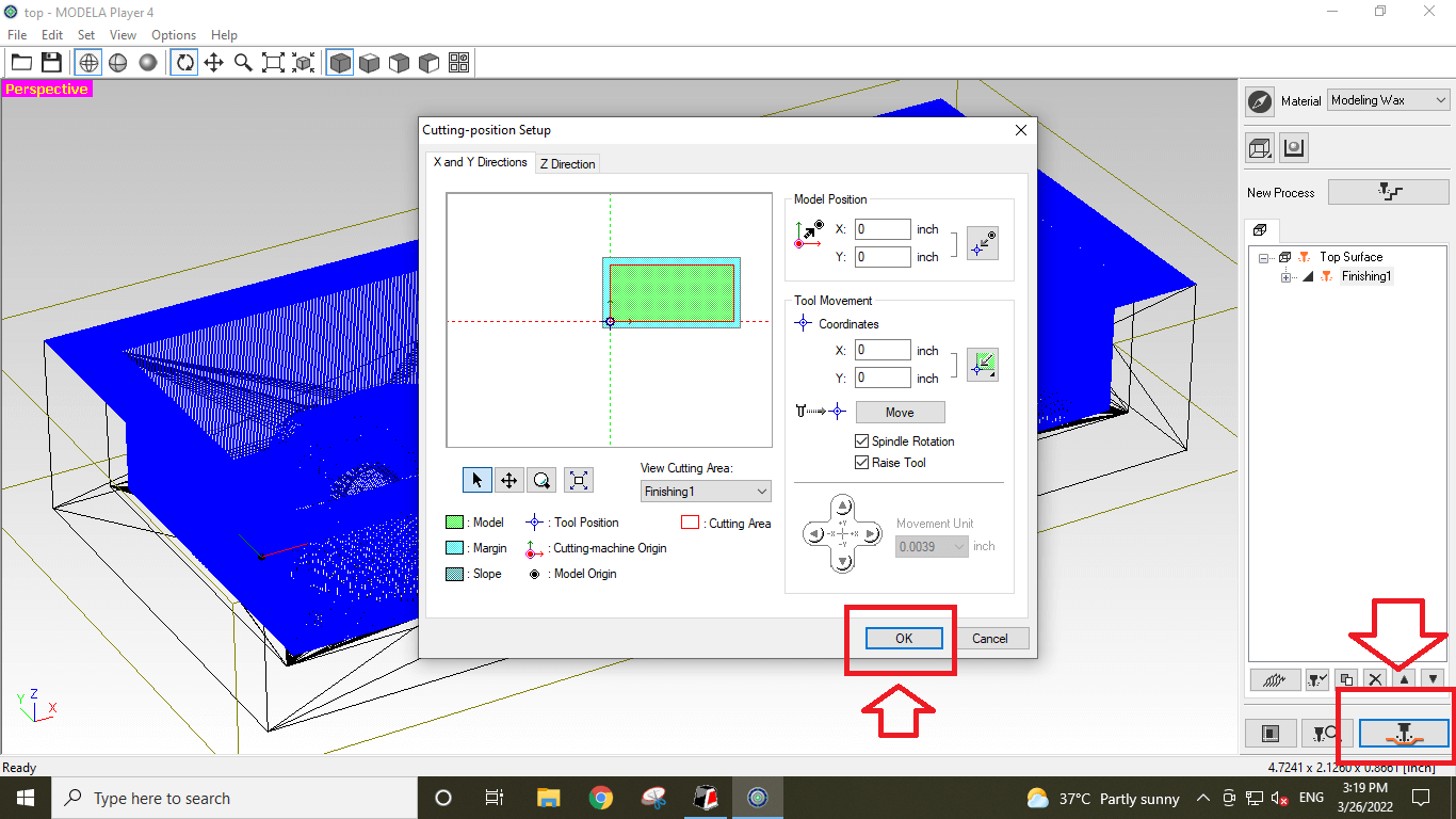
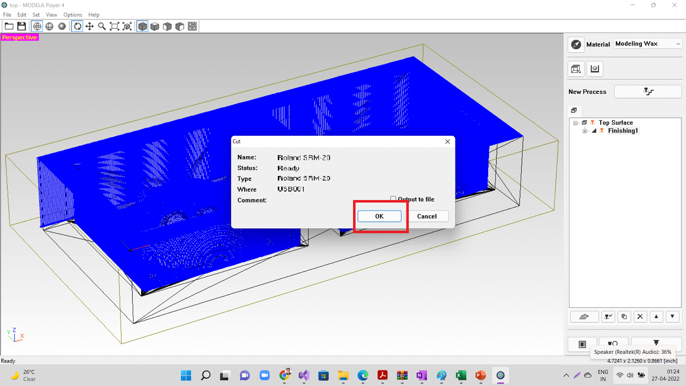
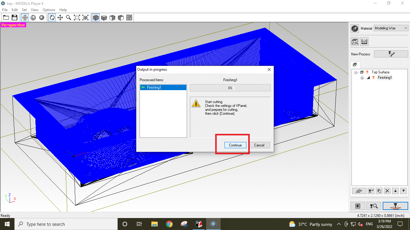
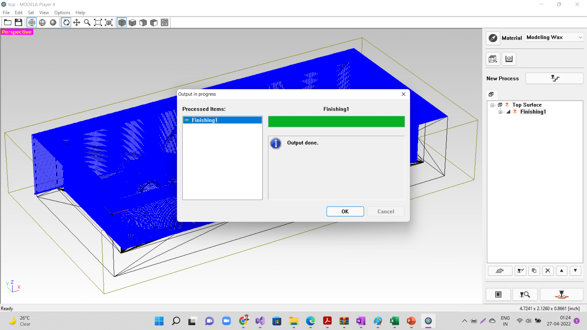
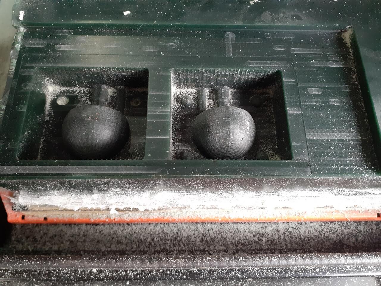
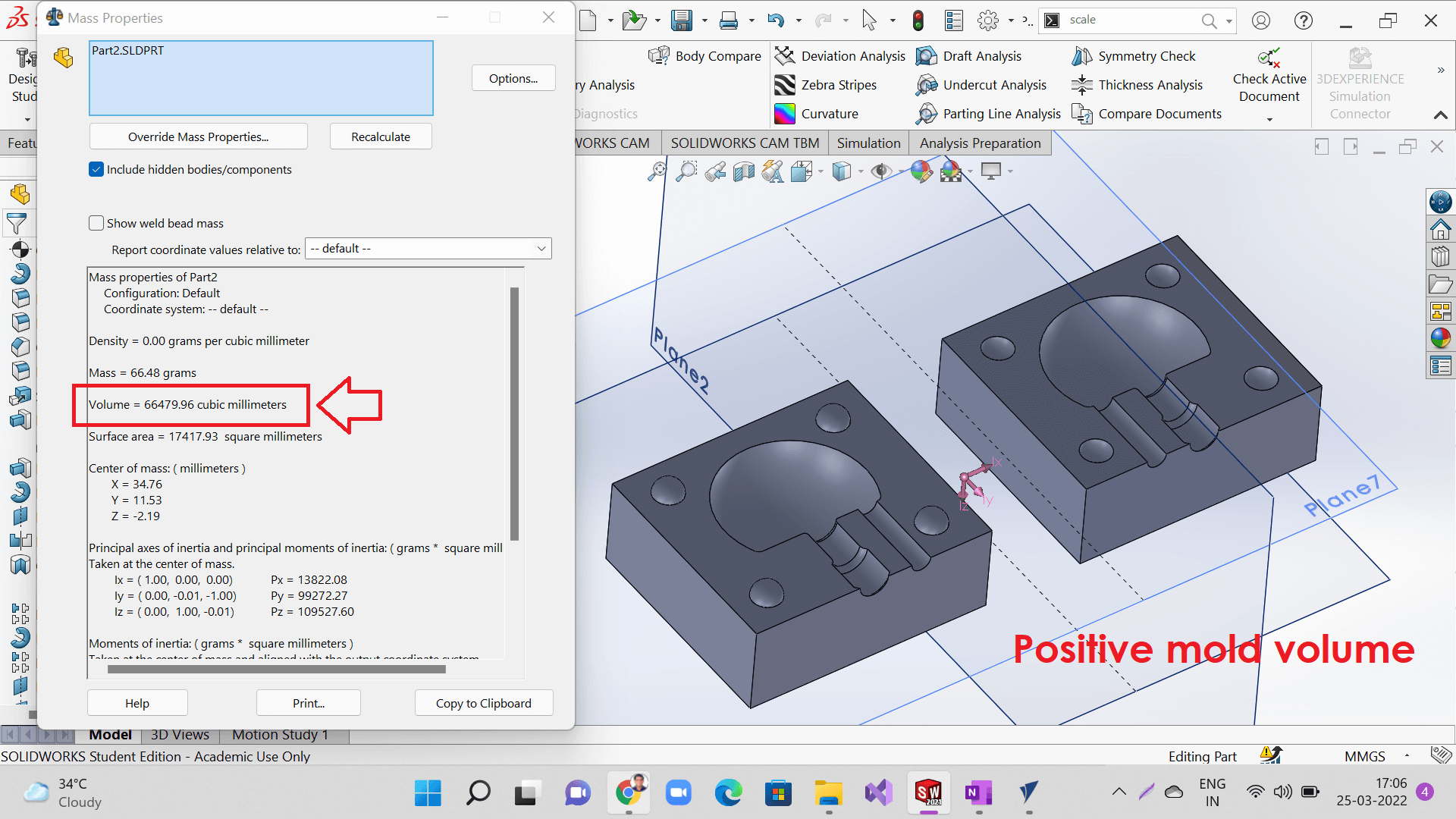
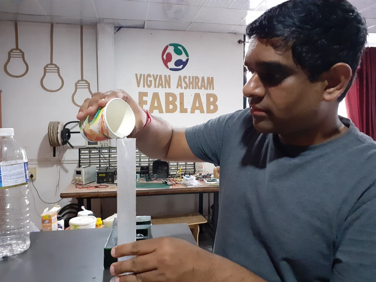
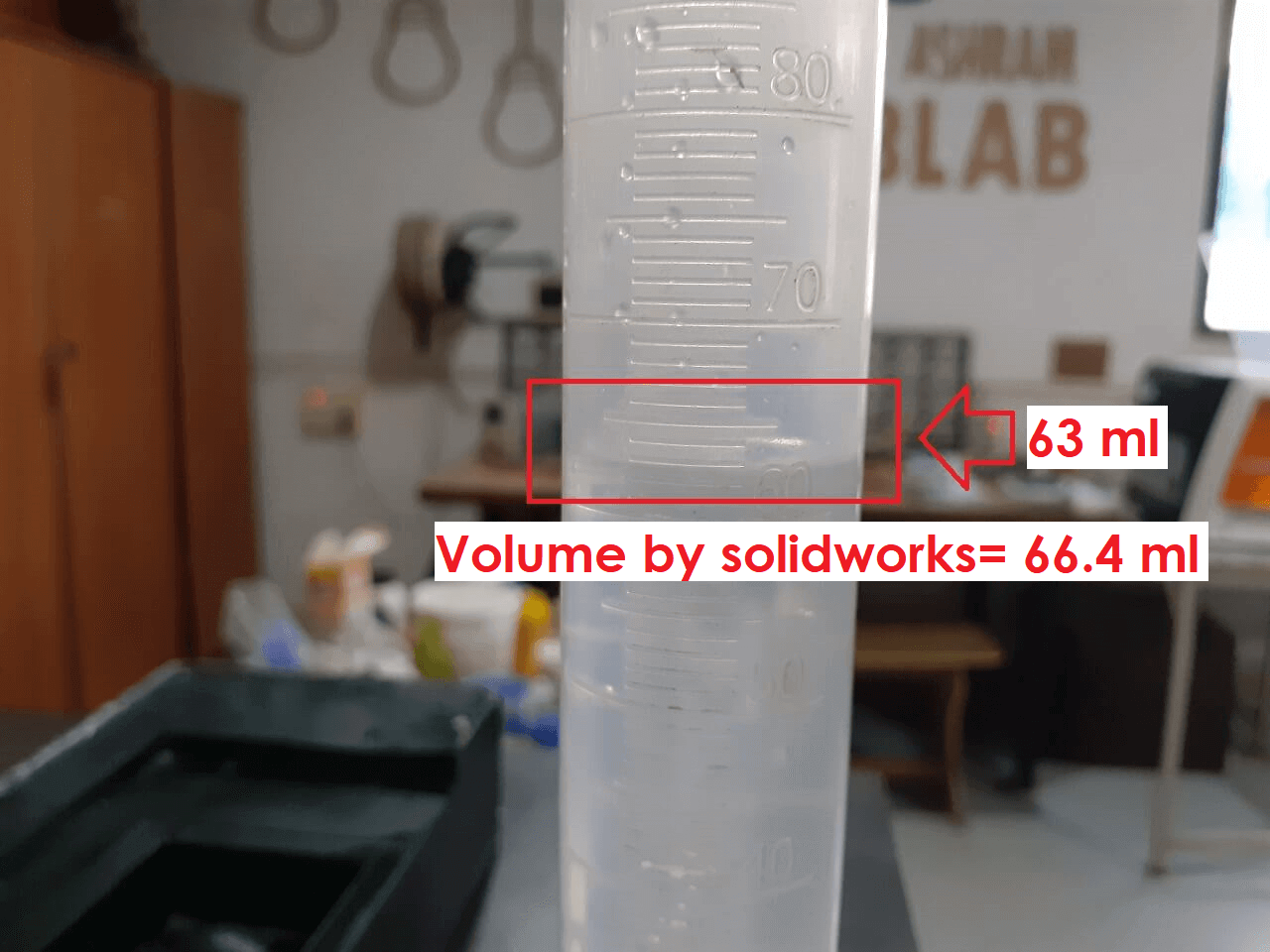
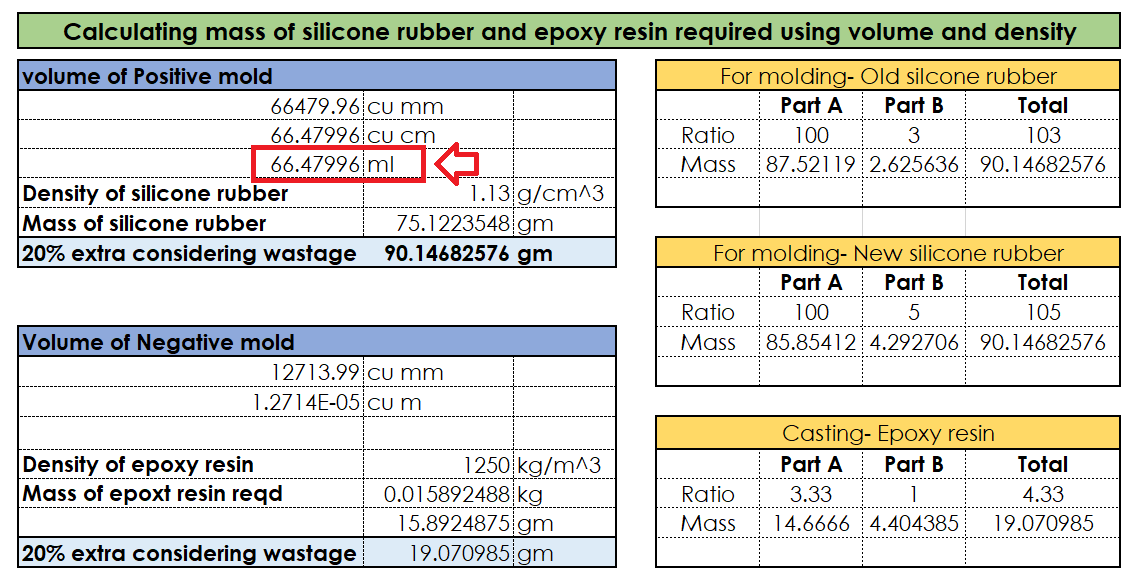
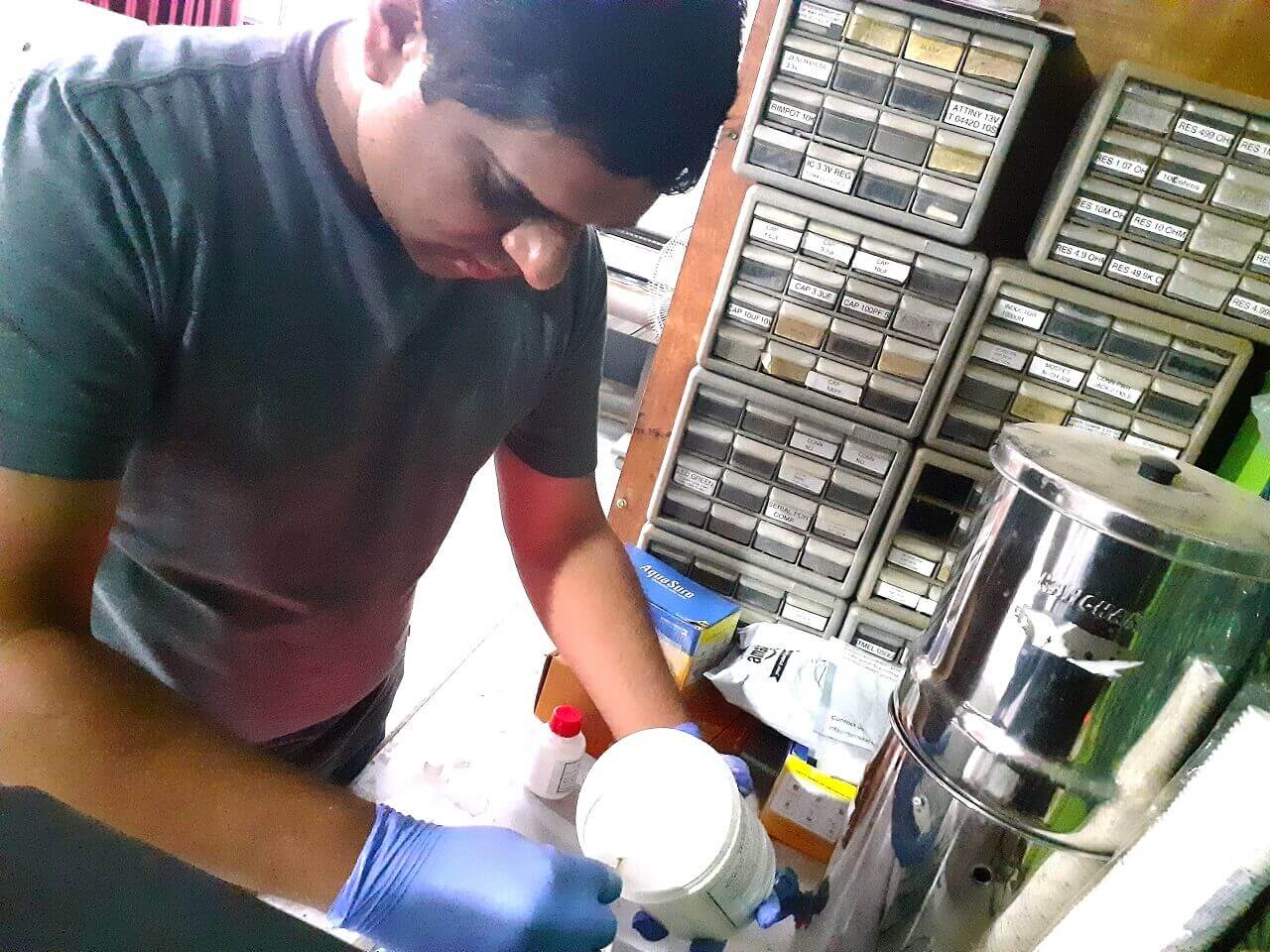
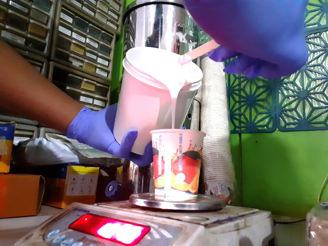
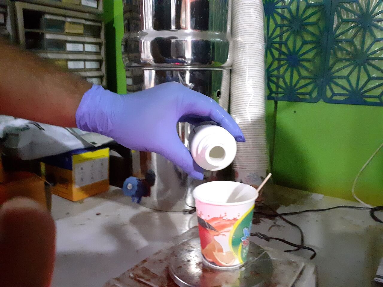
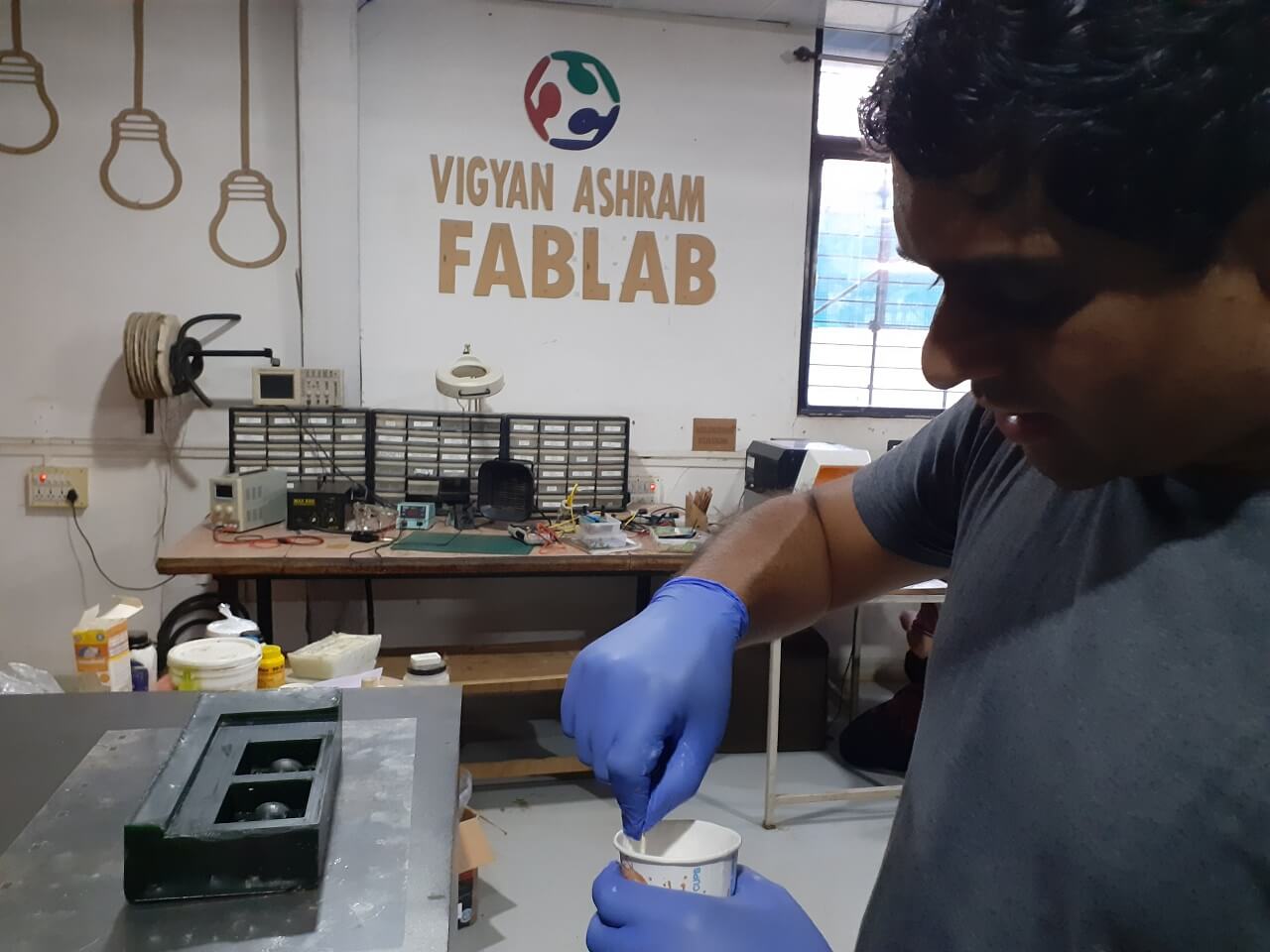
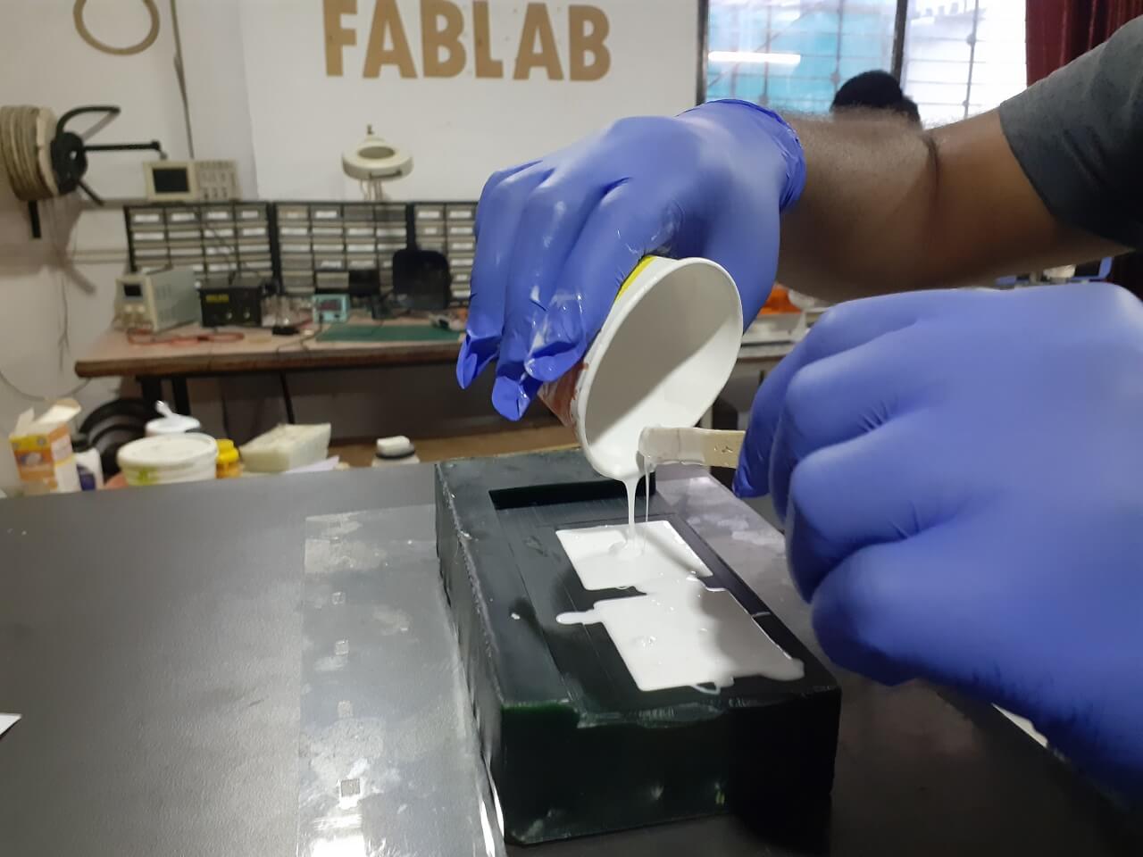
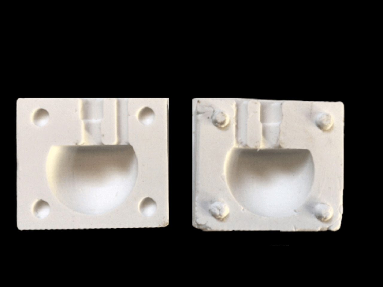
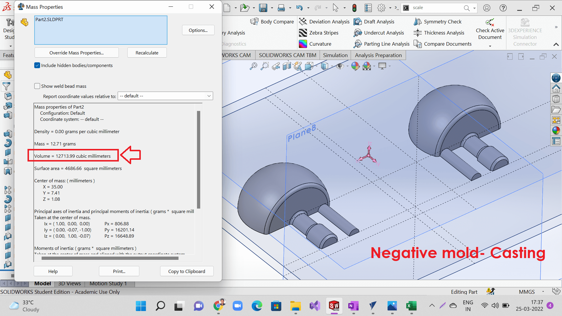
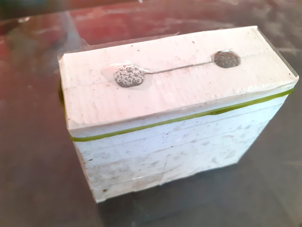
As the name suggests, resin casting is a casting process that involves the use of synthetic resin. To better understand how it works, you must first look at the synthetic resin used in this casting process. Synthetic resin is any type of resin that is converted into strong and rigid polymers via curing. In other words, it begins in a liquid state but converts to a solid state after being cured. Epoxy resin is known for its strong adhesive qualities, making it a versatile product in many industries. It offers resistance to heat and chemical applications, making it an ideal product for anyone needing a strong hold under pressure. Epoxy resin is also a durable product which can be used with various materials, including: wood, fabric, glass, china or metal. It is important to note, however; epoxy resin is not considered to be water resistant. Repeated moist or wet conditions can cause deterioration over time which will affect durability. Reference- Read more. Reference InstaMold is a temporary mold-making compound that is activated with water. It's perfect for making a quick and perfect reproduction of your treasured memorabilia, including 3D object. Reference- Data sheet for Instamold Hydrostone superx gypsum cement is an excellent product for manufacturing solid cast architectural, art novelty and statuary products. Hydrostone superx gypsum cement is extremely hard and has high compressive strength. It has high water absorption resistance while giving extremely fine detail duplication. Reference- Data sheet for Hydrostone This assignment is about documenting what we learned in Molding and casting week that includes understanding different materials used in molding and casting, review their safety data sheets and making their test casts. - Review the safety data sheets for each of your molding and casting materials - Flexwax We tested the above material by each one of us and went through their safety data sheets. We used all different molding and casting materials available in our Fab lab at Vigyan Ashram. We made their test casts and observed proportion, mixing methods and curing time for each one of the materials. We also learned which material can be used as a molding material and which one as casting material. Some of them can be used as both molding and casting materials. Click here to read more about our Group Assignment. - Design a mold around the stock and tooling that you will be using I wanted to make a self-inverting top using molding and casting process. Self-inverting tops are the tops that invert upside down on its own upon spinning. Since the center of the mass of top is below the center of circle, the top inverts on its own. I used Solidworks CAD software to design the top as below. Step 1: I drew a sketch considering the dimensions of the top I wanted to make. I on purpose made the top of the spherical surface to be flat so as to move the center of mass below the center of rotation of the top. As you can see below, the center of mass is shifted below the center of rotation of the top (origin of the circle drawn while modeling). I added a cavity around the top to create a positive mold. I kept the height of the cavity 4 mm above the tippie top so as to have a 4 mm thickness to the negative mold that I will be creating using silicone rubber. I added vent to the mold so that an air can be escaped out while pouring the silicone rubber and it will be spread uniformly inside the mold. I created mirror of the model so that the second half of the mold will be machined as a mirror to the first half of the mold as shown below. I added dowel pins (semi-spherical) to the first half and holes (semi-spherical) to the other half mold as shown below. The pins will be locked inside the holes to keep the two halves of the mold intact. To create a positive mold out of a machinable wax, I used modela player 4 software to generate the toolpaths for operations like surfacing, roughing and finishing paths. Before we use modela and toolpath generated, we need to use 'VPanel' for SRM-20 and set-up the job and XY and origin for the tool. I applied the double sided tape at the bottom of the stock, checked the level of the machine bed and also applied hot glue around the wax stock to make sure the job is stable and does not move during the machining process as we do not use any other clamps as that of any machining operations. A. Surfacing of the wax surface: I followed the steps below to generate surfacing toolpath. Step 1. Click 'File' and open the part stl file. Step 2. Click 'File' and click 'Select Machine' button. Next, choose machine name from the drop down and also add machine name as a printer name. Step 3. Click 'Set', 'Model' and select job orientation just the way you would like your mold to be milled on the machine. Step 4. Click 'Isometric view', and verify the job orientation one more time. Step 5. Once again click 'Set', 'Model' and select job origin as shown in the picture below. I have selected top left corner of my job to be the origin. Step 6. Now, select 'Modeling wax' as material (since I was going to use machinable wax). Click 'New Process' to generate the tool path. Step 7. Select 'Surfacing' tool path and click OK. Step 7. Select 'Cutting surface' as Top (+Z) as shown below. Step 8.Click 'Option', 'Add/Remove Tool' in case the tool you are going to use is not listed in to the standard tool library of modela. Otherwise, this step is not required always. Select any nearby sized tool available in the library and click 'Copy' to copy this tool as a new tool. Change the tool diameter and save the new tool in the library. Step 9. Now, I again verified that I have selected 'Modeling wax' as material. Again click 'New Process' to generate the tool path and select the newly added tool that you will be using on the machine. Step 10. Now, click 'Specified area' and change it to the below settings as shown it next two images. Also add depth of surfacing you would like to have. This depends on how uneven your original surface is and how much deep material you would like to remove to make it flat. Step 11. Now, choose 'Type of tool path' from the two options given below- 'Scan lines' or 'Unidirectional'. Also re-cofirm the cutting start position to be the top left corner of the job. For my job, I choose 'Scan lines' option though it would be time consuming as compared to the 'Unidirectional' option. Step 12. Now, select and/or edit 'Depth of cut' depending upon the total depth of surfacing you are going to do. Step 13. Let the 'Process name' be 'Surfacing1' and select 'Right now' option. Step 14. The tool path is now generated and seen on the right side hand side tree. Also verify the surfacing toolpath in 'isometric' and 'top' views as shown below. Step 15. Click on the 'Cutting' icon on the bottom right hand side of the UI as shown below. Click on 'Next' and 'Ok' buttons until the milling process is started. Since the tool origin was already set-up through Vpanel, the machine will start doing surfacing as shown below. Because of the wrong overlap I selected for ball-nose end mill, the surfacing of the stock was not done properly, it had tool marks as shown below. Then, I removed the ball-nose end mill tool again replaced it with 3.1 mm flat end mill. This is how surface finish looks like after surfacing has been done properly. B. Roughing of the wax surface: I followed the steps below to do generate the roughing toolpath. All the steps are same as that I followed for surfacing. Only difference is the process I have selected as 'Roughing' for generating the toolpath. When roughing was completed, I had removed a lot of shaving in between so there is a less amount of shaving seen in this picture. C. Finishing of the wax surface: I followed the steps below to do generate the finishing toolpath. All the steps are same as that I followed for surfacing and roughing. Only difference is the process I have selected as 'Finishing' for generating the toolpath. To create a negative mold using a positive mold, I needed a mold material. I used Moldsil15 silicone rubber. First of all I needed to calculate the mass of the material required. I found out the volume of the positive mold using Solidworks and also measured using the water. To calculate the mass of the silicone rubber required, I used the volume of the positive mold and density of silicone rubber. I considered 20% extra in case of any wastage. I then divided the Part A (silicone rubber) and Part B (Catalyst) in the ratio of 100:30 to find out the mass required for each of these parts as shown in the image below. Weighing Part A 86 gms. Adding Part B 4.3 gms. Stirring the mixture as prescribed (so that bubbles do not get formed inside the liquid mixture) for 3 minutes. The mold got filled and I waited for 24 Hrs for it to get cured properly. I allowed it to set properly. Here you go, the negative mold if ready after a wait of 24 hrs. It did not have bubbles except inside the dowel pins. I forgot to wipe clean the surface after I used water to measure the volume. There was some droplets of water that was trapped causing the dowel pins to have bubbles. I used casting epoxy resin to cast my final object (tippie top). I used the same method, took volume of a negative mold from solidworks as shown below. Using density of the epoxy resin, I calculated the mass of the epoxy resin required to completely fill the mold. I added 20% extra considering the wastage. The mold got filled with epoxy resin. I waited for another 24 Hrs for it to get cured properly. I allowed it to set properly. Finally, when I opened the mold after 24 hours, here I saw my casting. It had bubbles inside it. I was little disappointed though. Finally, I am again adding the video that I created for entire work on my individual assignment for this week. Click here to download all original files.The Basics of Resin Casting
In resin casting, liquid synthetic resin is mixed with a curing agent- typically at room temperature or near-room temperature. Next, the two substances are poured into a mold cavity. The curing agent then converts the resin into rigid polymers, essentially hardening it. After this chemical reaction has finished, the hardened casting is ejected and removed from the mold cavity. Reference#1- Read more., Reference#2- Read more.4. Epoxy Resin
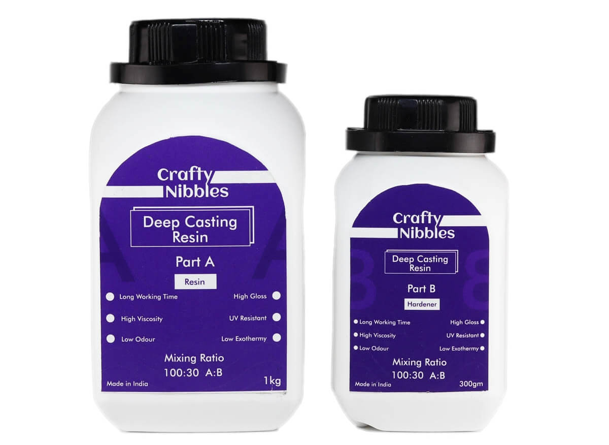
Casting epoxy resins are suitable for a variety of industrial and art related projects requiring a rigid, clear finished casting. It is mixed 100A:30B by weight (gram scale required) and features a very low viscosity for easy mixing and minimal bubble entrapment.
Details:
- Clear and optically transparent with a glass clear quality.
- It is a low viscous resin made specifically for casting.
- Use 100 parts resin to 30 part hardener by volume (100:30) to ensure a hard finish once set. You MUST follow the instructions accurately. Do NOT change the mixing ratio - this will alter the properties of the resin
- Stir Part A and Part B together thoroughly for at least 3 minutes.
- If cured at 25 degree C this resin should be touch dry within 24hours.
5. Instamold
InstaMold is perfectly safe to make a body cast with, and will make a replica which includes the finest of detail. InstaMold does not stick to the original object and once you have your temporary mold you can then make a number of permanent castings using other materials such as ArtPlaster, PermaStone, resin, or wax. InstaMold does not work well with clay. Reference- Read more.
6. Hydro-stone gypsum cement
It is used primarily in tooling and high quality art object applications. This is an extremely wear-resistant material. It cures Bright White when fully dry. Hydrostone is 40% to 50% harder than regular casting plaster. Works much like plaster in mixing, pouring, and setting. Reference- Read more.
Group Assignment Brief
Objectives of the Group Assignment:
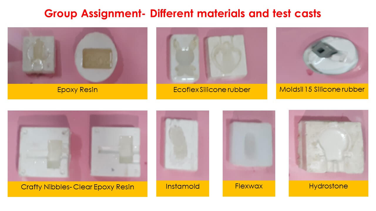
- Then make and compare test casts with each of them.Materials to be Tested:
- Machinable wax
- Silicone rubber
- Smooth-on's Ecoflex silicone rubber
- Hydro-stone's gypsum cement
- Instamold
- Epoxy resin
- MDF
Click here to go back to the topIndividual Assignment
Objectives of Individual Assignment:
- Mill it (rough cut + three-axis finish cut)
- Use it to cast parts
- Extra credit: Use more then two mold parts

1. Designing Mold
2. Milling a Mold

3. Creating a Negative Mold
4. Casting using Negative Mold
Click here to go back to the topDownload Original Files
What went well
In group assignment- We were able to read material safety data sheets for all different molding and casting material we had in out lab. We also could make test casts with these materials and compared them with each other.
In individual assignment- I was able to design my mold on time. That gave me enough time to mill the mold and cast.
What went wrong
In group assignment- There is nothing major that we did wrong in the group assignment.
In individual assignment- There are 3 things that went wrong with my individual assignment. One, the surface finish of the mold after surfacing operation had tool marks of the ball-nose tool. I did not choose the overlay value properly. Second, I did not clean wipe the water trapped inside the wax mold, hence my negative mold had bubbles on the dowel pins. Third, my final casting had air bubbles, may be because I did not shake it properly during pouring.
What I would do differently
- I would try using mdf as a mold material.
- I would try different molding and casting material.
Learning Outcomes
- I learned how to use Modela Player 4 software to generate toolpaths
- I learned basics of molding and casting and importance of sprue, gates and vents.
- I learned different materials used for molding and casting along with their safety data sheets.
- I learned how to use solidworks to calculate volume.