Week thirteenth assignment is the Networking and communication.In this week we are going understand how two microcontroller board communicate with each other.What are the communication protocol and how to use it. This week Neil has introduced as about various communication protocol like I2C,SPI,CAN etc.On next day our lab manager gave brief lecture on what to do in this assignment,what is networking and how it works.
Assignment-13
Networking and Communications
OBJECTIVES
Group assignment
- Send a message between two projects
Individual assignments
- Design, build, and connect wired or wireless node(s) with network or bus addresses.
Learning outcomes
- Demonstrate workflows used in network design
- Implement and interpret networking protocols and/or communication protocols
About Group Assignment
Task for the group assignment is to Send a message between two projects.As most of our group members used ESP32 wroom microcontroller in our final project, we are decide to try the communication between two ESP32 microcontrollers.For this communication we uesd BME280(Temperature & Humidity sensor) data and shearing through Wi-Fi between ESP32 devices.The mac addresses of two ESP32 devices given below.for more details click on About Group Assignmet.
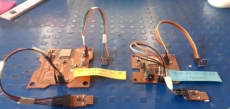
Mac addresses of ESP 32 devices.
Individual assignment on Networking and Communications
In this assignment we have design microcontroller boards,connect it with each others and identify the communication between them.As I have already design my final project board in "Input devices" , I have used this in the assignment aslo used BME280 and BH1750 sensors as nodes.The work flow for the assignment is as follows.
- About Networking and Communication.
- Parallel Communication
- Serial Communication.
- I2C Protocol
- ESP 32 communication with Sensors through I2C protocol
About Networking and Communication.
Networking
A computer network is a group of computers that use a set of common communication protocols over digital interconnections for the purpose of sharing resources located on or provided by the network nodes. The interconnections between nodes are formed from a broad spectrum of telecommunication network technologies, based on physically wired, optical, and wireless radio-frequency methods that may be arranged in a variety of network topologies.The nodes of a computer network may include personal computers, servers, networking hardware, or other specialised or general-purpose hosts. They are identified by hostnames and network addresses. Hostnames serve as memorable labels for the nodes, rarely changed after initial assignment. Network addresses serve for locating and identifying the nodes by communication protocols such as the Internet Protocol.(Wikipedia)
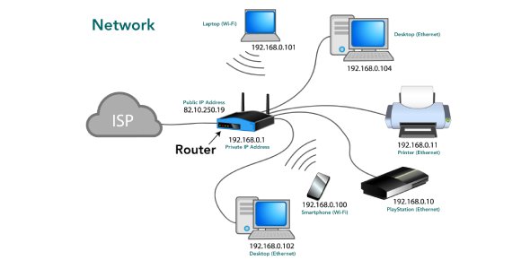
Computer Networking(Google source)
Communication.
Data communications refers to the transmission of this digital data between two or more computers and a computer network or data network is a telecommunications network that allows computers to exchange data. The physical connection between networked computing devices is established using either cable media or wireless media. The best-known computer network is the Internet.The field of networking and communication includes the analysis, design, implementation,and use of local, wide-area, and mobile networks that link computers together.The Internet itself is a network that makes it feasible for nearly all computers in the world to communicate.(Wikipedia)
(Google source)
Parallel Communication
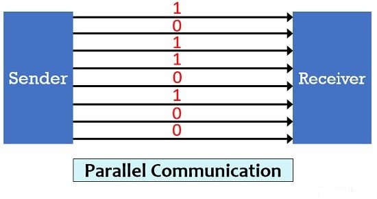
In data transmission, parallel communication is a method of conveying multiple binary digits (bits) simultaneously. It contrasts with serial communication, which conveys only a single bit at a time; this distinction is one way of characterizing a communications link.
The basic difference between a parallel and a serial communication channel is the number of electrical conductors used at the physical layer to convey bits. Parallel communication implies more than one such conductor. For example, an 8-bit parallel channel will convey eight bits (or a byte) simultaneously, whereas a serial channel would convey those same bits sequentially, one at a time. If both channels operated at the same clock speed, the parallel channel would be eight times faster. A parallel channel may have additional conductors for other signals, such as a clock signal to pace the flow of data, a signal to control the direction of data flow, and handshaking signals.
Parallel communication is and always has been widely used within integrated circuits, in peripheral buses, and in memory devices such as RAM. Computer system buses, on the other hand, have evolved over time: parallel communication was commonly used in earlier system buses, whereas serial communications are prevalent in modern computers.
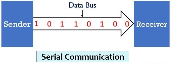
Serial Communication.
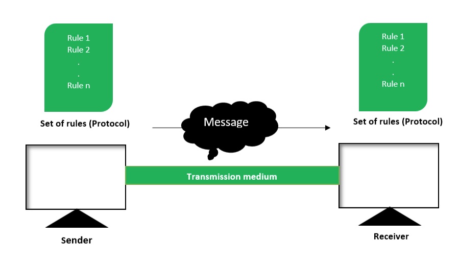
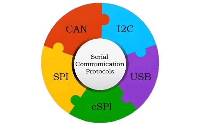
Serial communication is the most widely used approach to transfer information between data processing equipment and peripherals. In general, communication means interchange of information between individuals through written documents, verbal words, audio and video lessons. Every device might it be your Personal computer or mobile runs on serial protocol. The protocol is the secure and reliable form of communication having a set of rules addressed by the source host (sender) and destination host (receiver). To have a better insight, I have explained the concept of serial communication.(codrey.com)
In embedded system, Serial communication is the way of exchanging data using different methods in the form of serial digital binary. Some of the well-known interfaces used for the data exchange are RS-232, RS-485, I2C, SPI etc.
Types of serial communication.
What is Serial communication?
In serial communication, data is in the form of binary pulses. In other words, we can say Binary One represents a logic HIGH or 5 Volts, and zero represents a logic LOW or 0 Volts. Serial communication can take many forms depending on the type of transmission mode and data transfer. The transmission modes are classified as Simplex, Half Duplex, and Full Duplex. There will be a source (also known as a sender) and destination (also called a receiver) for each transmission mode.
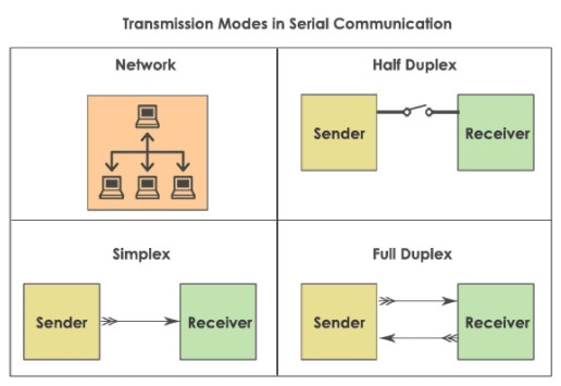
Types of Transmission Modes
Simplex method : The Simplex method is a one-way communication technique. Only one client (either the sender or receiver is active at a time). If a sender transmits, the receiver can only accept. Radio and Television transmission are the examples of simplex mode.
Half Duplex mode : In Half Duplex mode, both sender and receiver are active but not at a time, i.e. if a sender transmits, the receiver can accept but cannot send and vice versa. A good example is an internet. If a client (laptop) sends a request for a web page, the web server processes the application and sends back the information.
Full Duplex mode : The Full Duplex mode is widely used communication in the world. Here both sender and receiver can transmit and receive at the same time. An example is your smartphone.
Serial data can be transferred in two ways-Asynchronous and Synchronous
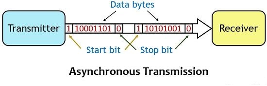
Asynchronous serial communication
Asynchronous serial communication is a form of serial communication in which the communicating endpoints' interfaces are not continuously synchronized by a common clock signal. Instead of a common synchronization signal, the data stream contains synchronization information in form of start and stop signals, before and after each unit of transmission, respectively. The start signal prepares the receiver for arrival of data and the stop signal resets its state to enable triggering of a new sequence. A common kind of start-stop transmission is ASCII over RS-232, for example for use in teletypewriter operation.(Wikipedia)
(Circuit Globe)
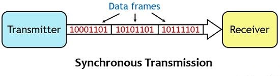
Synchronous serial communication
Synchronous serial communication describes a serial communication protocol in which "data is sent in a continuous stream at constant rate".Synchronous communication requires that the clocks in the transmitting and receiving devices are synchronized – running at the same rate – so the receiver can sample the signal at the same time intervals used by the transmitter. No start or stop bits are required. For this reason "synchronous communication permits more information to be passed over a circuit per unit time"than asynchronous serial communication. Over time the transmitting and receiving clocks will tend to drift apart, requiring resynchronization.(Wikipedia)
(Circuit Globe)
About I2C Protocol
I2C communication is the short form for inter-integrated circuits. It is a communication protocol developed by Philips Semiconductors for the transfer of data between a central processor and multiple ICs on the same circuit board using just two common wires.
Owing to its simplicity, it is widely adopted for communication between microcontrollers and sensor arrays, displays, IoT devices, EEPROMs etc.This is a type of synchronous serial communication protocol. It means that data bits are transferred one by one at regular intervals of time set by a reference clock line.(Electronichub.org)
Features of I2C communication.
- Only two common pins (wires) are required to control any device/IC on the I2C network.
- No need of prior agreement on data transfer rate like in UART communication. So the data transfer speed can be adjusted whenever required.
- Simple mechanism for validation of data transferred.
- Uses 7-bit addressing system to target a specific device/IC on the I2C bus.
- I2C networks are easy to scale. New devices can simply be connected to the two common I2C bus lines.
Following are some important features of I2C communication.
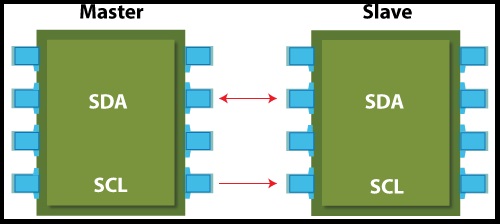
The physical I2C
I2C Bus (Interface wires) consists of just two wires and are named as Serial Clock Line (SCL) and Serial Data Line (SDA). The data to be transferred is sent through the SDA wire and is synchronized with the clock signal from SCL. All the devices/ICs on the I2C network are connected to the same SCL and SDA lines as shown below:(circuitbasics.com)
Interfacing of I2C wires.
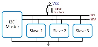
All the devices connected on same wires.
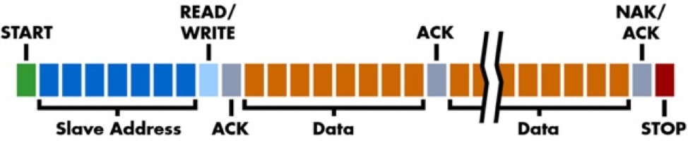
HOW I2C WORKS?
With I2C, data is transferred in messages. Messages are broken up into frames of data. Each message has an address frame that contains the binary address of the slave, and one or more data frames that contain the data being transmitted. The message also includes start and stop conditions, read/write bits, and ACK/NACK bits between each data frame:
Working of I2C protocol.
Start Condition: The SDA line switches from a high voltage level to a low voltage level before the SCL line switches from high to low.
Stop Condition: The SDA line switches from a low voltage level to a high voltage level after the SCL line switches from low to high.
Address Frame: A 7 or 10 bit sequence unique to each slave that identifies the slave when the master wants to talk to it.
Read/Write Bit: A single bit specifying whether the master is sending data to the slave (low voltage level) or requesting data from it (high voltage level).
ACK/NACK Bit: Each frame in a message is followed by an acknowledge/no-acknowledge bit. If an address frame or data frame was successfully received, an ACK bit is returned to the sender from the receiving device.
ESP-32 communication with BME280 through I2C.
In my final project I used ESP32 D wroom microcontroller.I have design the microcontroller bard given in the Input device assignment.In project i used the MBE280 sensor for the measurement of temperature and Humidity measurement.The BME280 follow the I2C communication protocol for communication.In ESP 32 there are by default two I2C pins as shown in the image.
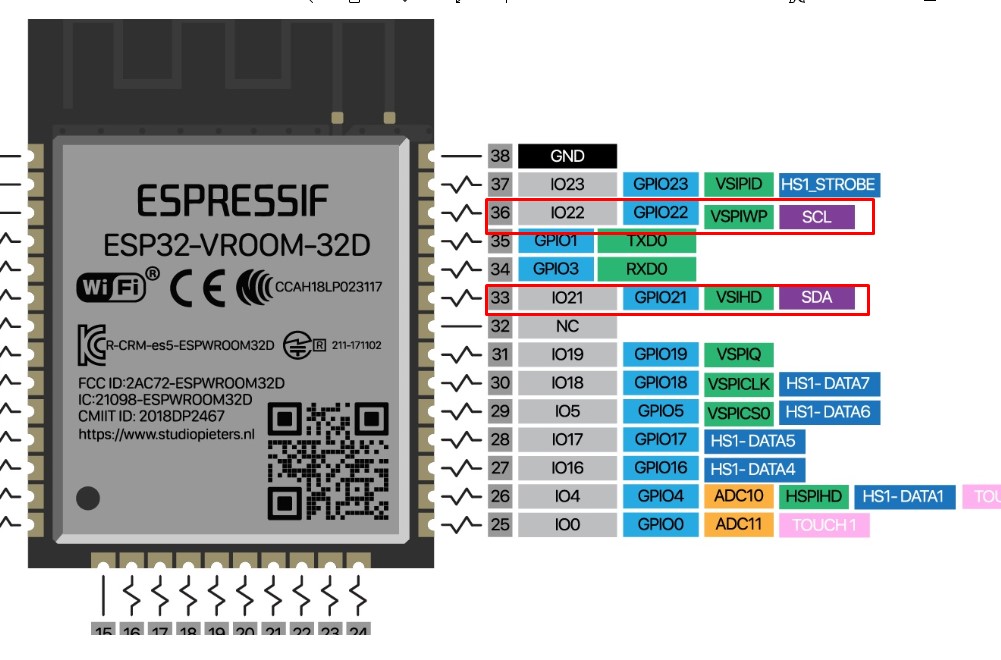
Default I2C pins of ESP 32.(Google source)
Since BME280 sensor communicates using I2C communication protocol, so for the wiring,I can use the default ESP32 I2C pins as shown in the following table:
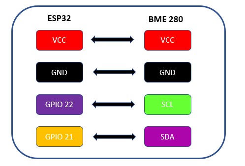
I2C Pin connection between ESP32 and BME280.
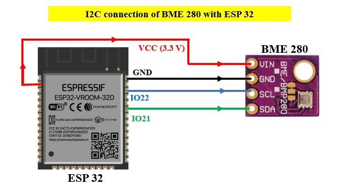
I2C connection of ESP32 with BME280.
Programming code
The programming code for Communication between ESP32 and BME280 as given below.
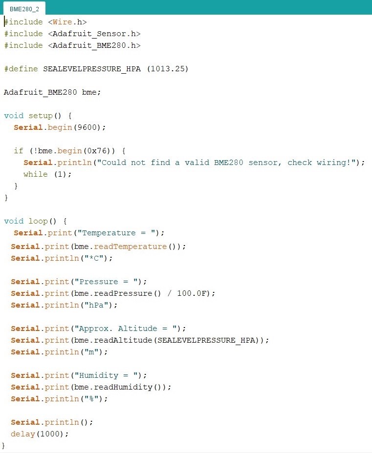
- The programming code statred with the needed library.Since its I2C communication I used the "Wire.h" library.for BME 280 interfacing used "Adafruit_Sensor" and "Adafruit_BME280" libraries
- By default I2C communication protocol,need to create an Adafruit_BME280 object called bme.
- In Setup(), start the communication.
- Serial.begin(9600):start the communication between the computer and the microcontriller.
- (!bme.begin(0x76)):Microcontroller initialize the sensor.Here the sensor is initialize having defaut address 0X76.
- If not getting output on serail monitor just check the address by using I2C scanner sketch.
I follow the Random Nerd Tutorials for this programming.
Programming Output
The programming output for Communication between ESP32 and BME280 as given below.
ESP-32 communication with BME280 and BH1750 through I2C.
In my final project I have aslo used light and measure its intensity.For this I used the BH1750 light intensity sensor which also working I2C communication protocol.So I trying to connect both BME-280 (Temperature & Humidity sensor)and BH1750(Light Intensity sensor) to the ESP32 microcontroller through the I2C.I tried to combine the BME-280 and BH-1750 code and find its out put on serial monitor.
Since both BME280 and BH1750 sensor communicates using I2C communication protocol, so for the wiring can set on the default ESP32 I2C pins as shown in the following table:
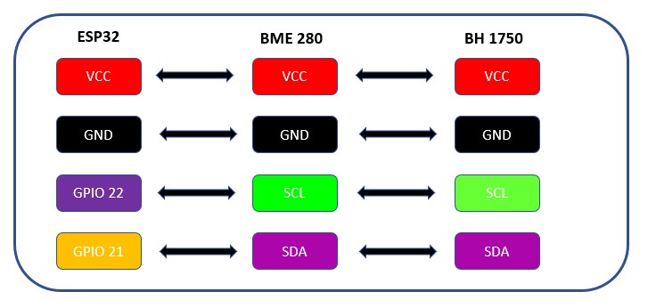
I2C Pin connection between ESP32 and BME280.
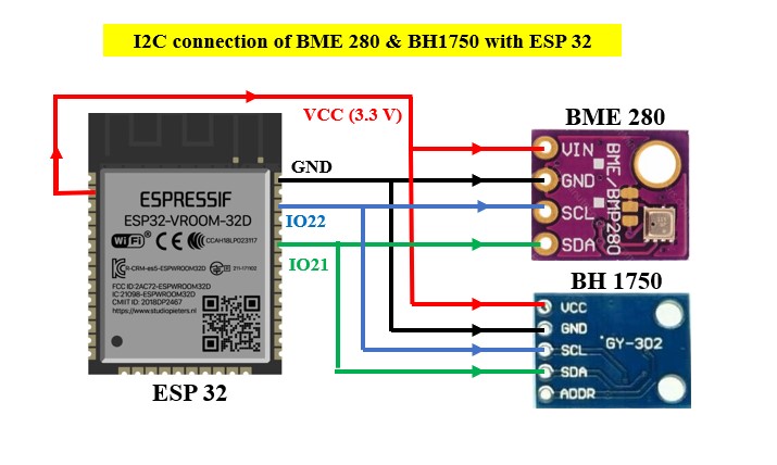
I2C connection of ESP32 with BME280 and BH1750.
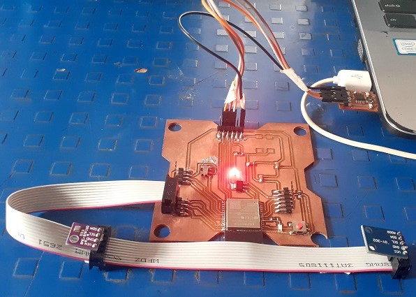
Actual connection of ESP32 with BME280 and BH1750.
Programming code
The programming code for Communication between ESP32 with BME280 and BH1750 as given below.
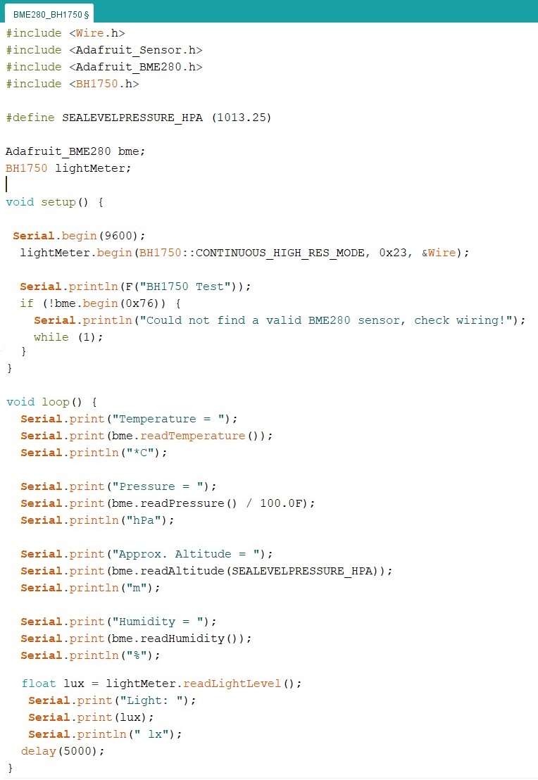
- The programming code statred with the needed library.Since its I2C communication I used the "Wire.h" library.for BME 280 interfacing used "Adafruit_Sensor", "Adafruit_BME280" libraries and for BH 1750 interfacing used "BH 1750" library.
- By default I2C communication protocol,need to create an Adafruit_BME280 object called bme similarly for BH 1750 obect called lightMeter.
- In Setup(), start the communication.
- Serial.begin(9600):start the communication between the computer and the microcontroller.
- lightMeter.begin :Microcontroller initialize BH 1750 sensor with default address.
- (!bme.begin(0x76)):Microcontroller initialize the BME280 sensor.Here the sensor is initialize having defaut address 0X76.
- The serial monitor display the ouput in required format.
- If not getting output on serail monitor just check the address by using I2C scanner sketch.
I follow the Random Nerd Tutorials for this programming.
Programming Output
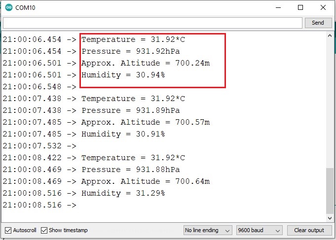
The programming output for Communication between ESP32 with BME280 and BH1750 as given below.
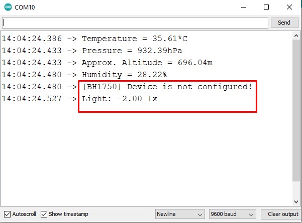
Error in the BH1750 output.
On the serial monitor out put there is an error.The parameters measured by BME-280 are displayed on the serial monitor but the light intensity measured by BH 1750 is not displayed.The error as shown in the image.
Trouble shooting the Error
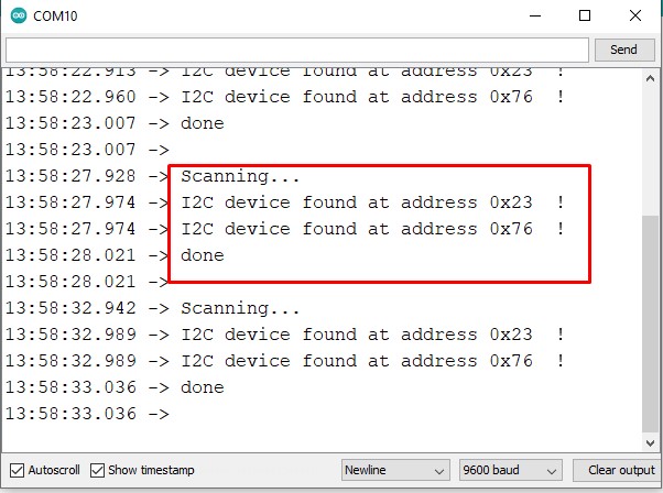
For trouble shooting the error,as mention if the serial monitor does not display the output firstly check the address of the connected sensors.so I used I2C scanner code run it to identified the addresses.the output on serial monitor is as shown in the image.
I2C scanner shows only one device.
In I2C Scanner code output only one address is display while I have connected two sensors.Means the microcontroller, In I2C communication does not get the address of second sensor.As per my friend Mohit,the address issue my be due to loose connection so just check all the sensos connected properly or not.we are going through the program code I have uesd and compare it with basic example.With this we identify the error as shown in the image.
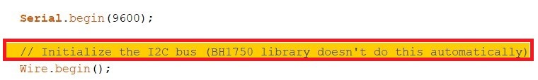
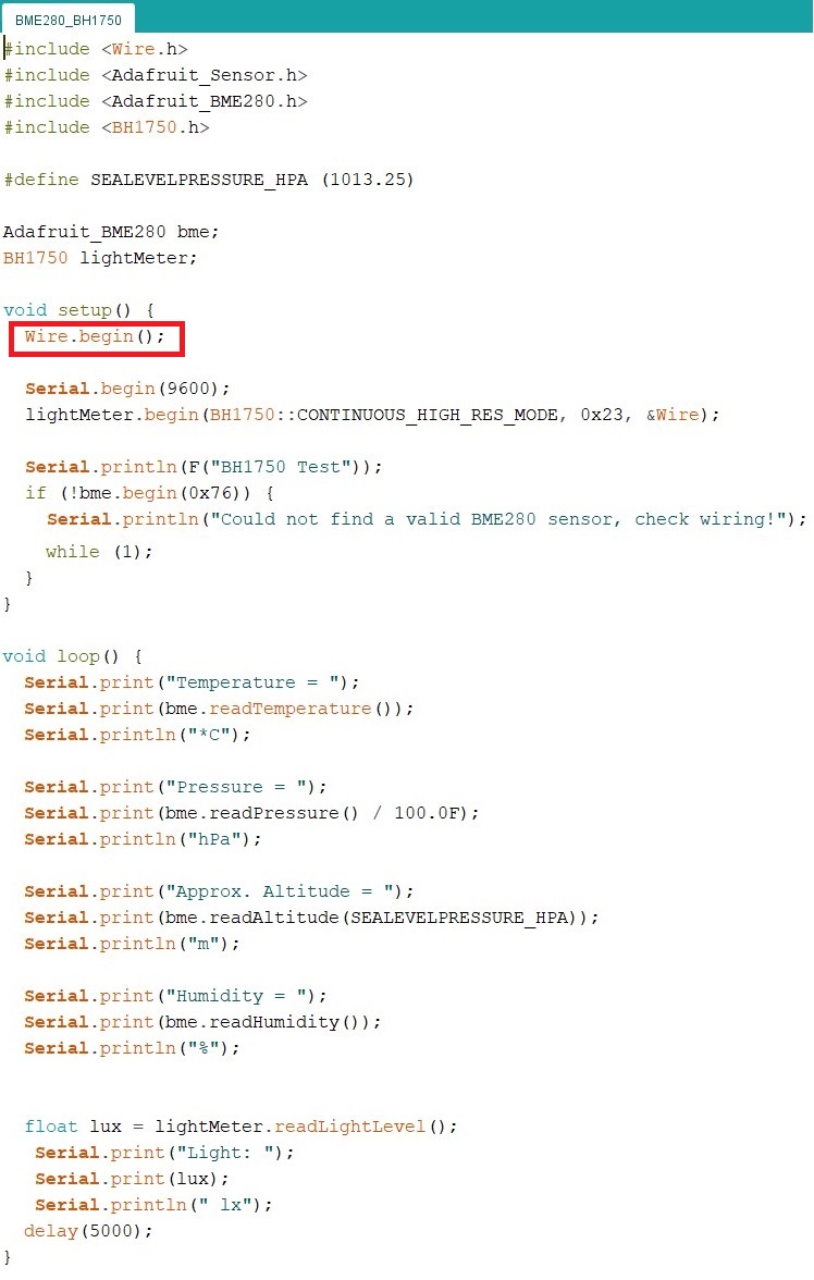
Initialize wire library specially for BH1750.
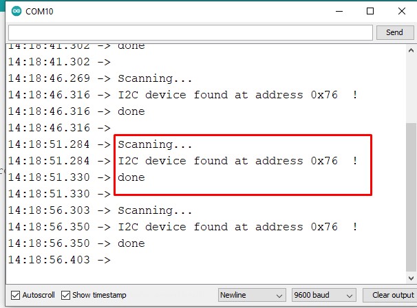
For BME 280 I2C communication there is no need to initialize "wire" library , as it is already presnet "Adafruit_BME280".But for BH1750 it is necessory to initialize "wire" library.So the problem is solved.The I2C scanner code output shows the address of two snsors as shown in the image.
I2C scanner shows addresses of two devices.
The modified code and its output on serial monitor is given in the followng images.
Programming Output
The required programming output for Communication between ESP32 with BME280 and BH1750 as given below.
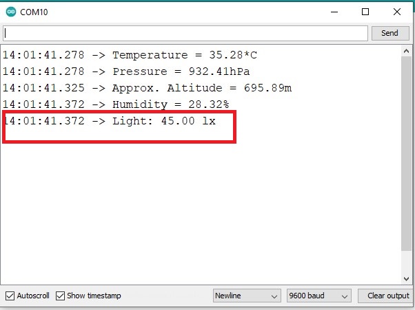
The output shows the light intensity as required.
The I2C connection of ESP32 with BM280,BH1750 and programming output as shown in video
Learning Outcomes
- I introduced with different communication protocols.
- Find the difference between parallel and serial communication.
- Knowing about the different transmission mode of serial communication.
- I Introduced with I2C communication and how it works.
- Identified the I2C communication between MCU and Sensors.
- Find the importance of "Wire" library in I2C communication.
Downloads
SAMS-Smart Azolla Multiplier System by Anand S. Tale is licensed under CC BY-SA 4.0![]()
![]()
![]()