Week tenth assignment is the Input devices.Input devices are nothing but the sensors.In this week we have to use any sensor.The sensor sense the input values and given to the design MCU to process the input values.We can display it or uesd to run any other application.
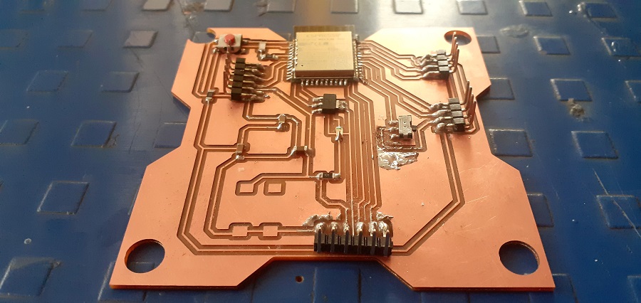
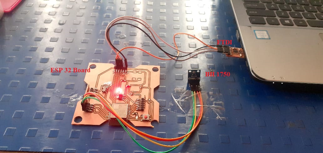
Hero shot.
Assignment-10
Input Devices
OBJECTIVES
Group assignment
- Probe an input device(s)'s analog and digital signals
- Document your work (in a group or individually)
Individual assignments
- Measure something: add a sensor to a microcontroller board that you have designed and read it.
Learning outcomes
- Demonstrate workflows used in sensing something with input device(s) and MCU board
About Group Assignment
Task for the group assignment is to identify the different sensors.Probe the senors with DSO and compare the signal level that is digital and analog.For more information of group assignmet click on About Group Assignment.
Individual assignment on Input Devices
In this assignment we have to uesd any sensor (Input Device)connected it with self design MCU and find its out put on serial monitor.In my final project I used ESP32 Wroom 32D microcontroller, BME 280 (Temperature & Humidity Sensor)and Bh1750(Lux module) so for input devices assignment I started with the same.The work flow of the assignment is given below.
- About Input devices (Sensor)
- ESP 32 Microcontroller
- BME 280
- BH1750
- Design Microcontroller Board
- Schematic and Board of ESP32 In Eagle
- Interfacing Microcontroller with Sensors
- Programming of ESP32 Microcontroller.
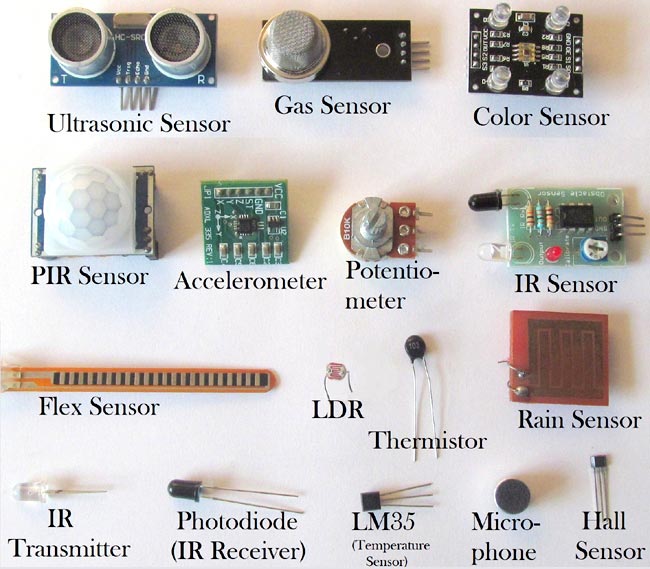
About Input devices (Sensor)
A sensor is defined as a device or a module that helps to detect any changes in physical quantity like pressure, force or electrical quantity like current or any other form of energy. After observing the changes, sensor sends the detected input to a microcontroller or microprocessor.
Finally, a sensor produces a readable output signal, which can be either optical, electrical, or any form of signal that corresponds to change in input signal. In any measurement system, sensors play a major role. In fact, sensors are the first element in the block diagram of measurement system, which comes in direct contact with the variables to produce a valid output.
Classification of Sensor
Active Sensors
Active sensors are the type of sensors that produces output signal with help of external excitation supply. The own physical properties of the sensor varies with respect to the applied external effect. Therefore, it is also called as Self Generating Sensors.Examples: LVDT(Linear Variable Differential Transformer) and strain gauge.
Passive Sensors
Passive sensors are the type of sensors that produces output signal without the help of external excitation supply. They do not need any extra stimulus or voltage. Example: Thermocouple, which generates a voltage value corresponding to the heat, applied. It does not require any external power supply.
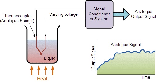
Analogue Sensors
Analogue Sensors produce a continuous output signal or voltage which is generally proportional to the quantity being measured. Physical quantities such as Temperature, Speed, Pressure, Displacement, Strain etc are all analogue quantities as they tend to be continuous in nature. For example, the temperature of a liquid can be measured using a thermometer or thermocouple which continuously responds to temperature changes as the liquid is heated up or cooled down.
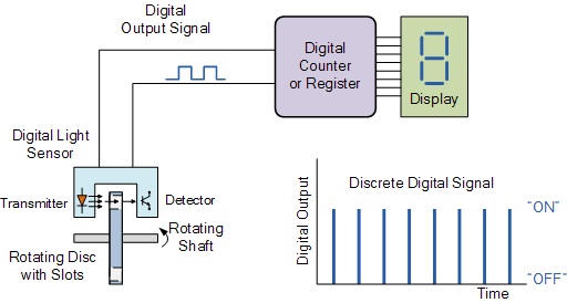
Digital Sensors
As its name implies, Digital Sensors produce a discrete digital output signals or voltages that are a digital representation of the quantity being measured. Digital sensors produce a Binary output signal in the form of a logic “1” or a logic “0”, (“ON” or “OFF”). This means then that a digital signal only produces discrete (non-continuous) values which may be outputted as a single “bit”, (serial transmission) or by combining the bits to produce a single “byte” output (parallel transmission).
About BME 280 Sensor
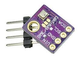
The BME280 is as combined digital humidity, pressure and temperature sensor based on proven sensing principles. The sensor module is housed in an extremely compact metal-lid LGA package with a footprint of only 2.5 × 2.5 mm² with a height of 0.93 mm. Its small dimensions and its low power consumption allow the implementation in battery driven devices such as handsets, GPS modules or watches. The BME280 is register and performance compatible to the Bosch Sensortec BMP280 digital pressure sensor.For more infornation click on BME280 Datasheet.
- It is available in metal lid LGA package with dimensions of 2.5x 2.5x 0.93 mm³.
- Its Interface protocol is I²C and SPI.
- It Supply Voltage is 1.71 to 3.6 V.
- Its temperature range is -40 to +85°C.
- Its humidity range is 0-100% real. humidity.
- Its pressure range is 300-1100 hPa.
- Humidity sensor and pressure sensor can be independently enabled/disabled.
The features of BME 280
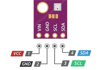
- VIN is the power supply for the module which can be anywhere between 3.3V to 5V.
- GND should be connected to the ground
- SCL is a serial clock pin for I2C interface.
- SDA is a serial data pin for I2C interface.
The BME280 module has only 4 pins that interface it to the outside world. The connections are as follows:
About BH1750 Light Sensor
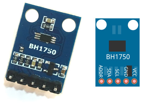
BH1750 is a 16-bit digital ambient light sensor developed by Rohm Semiconductors which can accurately measure the light intensity over a wide range. This sensor has a breakout board that consists of BH1750 sensor along with a 16-bit analog to digital converter.For more infornation click on BH1750 Datasheet.
How the Light Sensor Works?
It contains a photodiode which senses the light and produce electricity which is proportional to the light intensity. A photodiode is a semiconductor p-n junction device that converts light into an electrical current. The current is generated when photons are absorbed in the photodiode. Photodiodes may contain optical filters, built-in lenses, and may have large or small surface areas.
- Operating Voltage = 2.4V to 3.6V
- Light Intensity Range = 1 to 65535 LUX (small variation of +/- 20%)
- It consumes 0.12mA current and in power-down mode, this value is further reduced to 0.01µA.
- Communication Interface: I2C
- Built-in Illuminance to Digital Converter
- Minimum IR Radiations Effect
- Digital Output Format ( that makes it easy to interface with microcontrollers)
The features of BH1750 Light Sensor
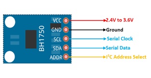
- GND: Pin1 is a ground pin.
- ADDR: It sets the address of the I2C interface. Connect this pin either to the ground or Vcc after selecting address via I2C.
- SDA: Serial Data Address pin transfers data through I2C bus.
- SCL: It is a serial clock pin for communication through I2C interface.
- Vcc: Apply 3.3V-5V at this pin.
The BME280 module has only 5 pins that interface it to the outside world. The connections are as follows:
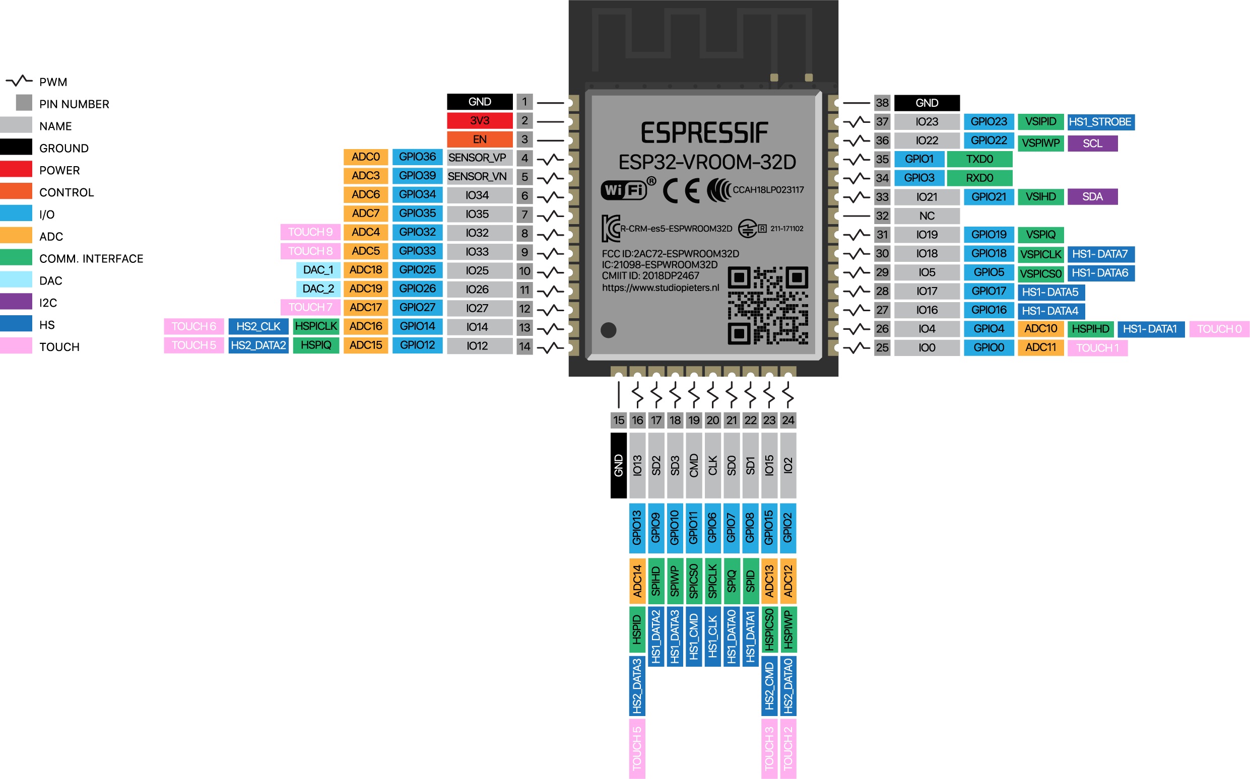
About ESP 32 Microcontroller
ESP32 is a series of low-cost, low-power system on a chip microcontrollers with integrated Wi-Fi and dual-mode Bluetooth. The ESP32 series employs a Tensilica Xtensa LX6 microprocessor in both dual-core and single-core variations and includes built-in antenna switches, RF balun, power amplifier, low-noise receive amplifier, filters, and power-management modules. ESP32 is created and developed by Espressif Systems, a Shanghai-based Chinese company, and is manufactured by TSMC using their 40 nm process. It is a successor to the ESP8266 microcontroller.For more infornation click on ESP32 Wroom 32D Datasheet.
- Microprocessor : Tensilica Xtensa LX6
- Maximum Operating Frequency : 240MHz
- Operating Voltage : 3.3V
- Analog Input Pins : 12-bit, 18 Channel
- DAC Pins : 8-bit, 2 Channel
- Digital I/O Pins : 39 (of which 34 is normal GPIO pin)
- DC Current on I/O Pins : 40 mA
- DC Current on 3.3V Pin : 50 mA
- SRAM : 520 KB
- Communication : SPI(4), I2C(2), I2S(2), CAN, UART(3)
- Wi-Fi : 802.11 b/g/n
- Bluetooth : V4.2 – Supports BLE and Classic Bluetooth
ESP32 Technical Specifications:
Design Microcontroller ESP32 Board
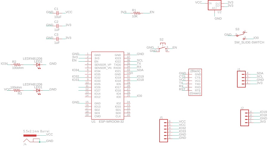
Schematic of ESP32 In Eagle
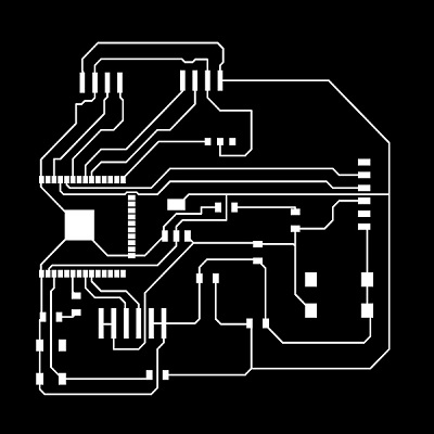
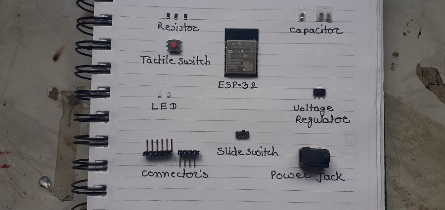
Microcontroller plays an importantant roll in in put devives.Now as per assignment we have to used self design microcontroller board and used it to check the sensors (input devices).so with I have tried to design the my ESP32 board with reference of Hellow ESP32.the Schematic of consist of ESP32 Wroom 32D microcontroller,3.3v votage regulator,FTDI,2 four pins connectors for input devices,one six pins connector for output devices,2 LEDs of power/signal,resistors and capacitors
Schemtic of ESP 32
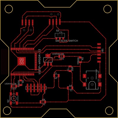
ESP32 Board
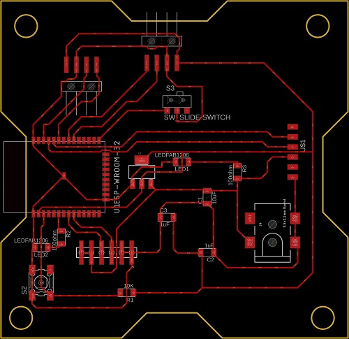
Modified ESP32 Board
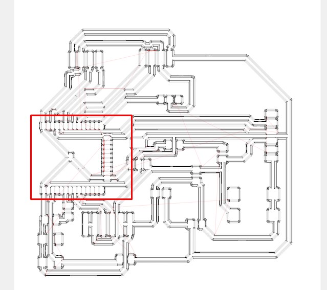
ESP32 Trace
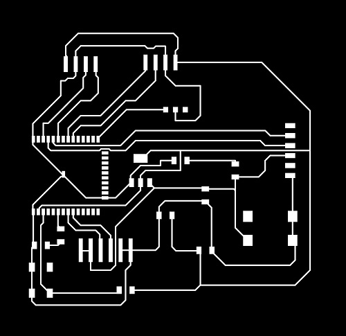
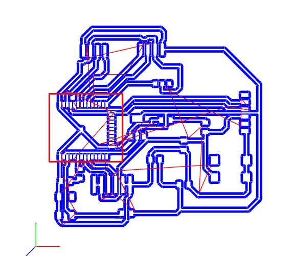
Modified ESP32 Trace
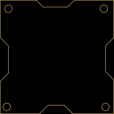
ESP 32 cutout
Milling,Stuffing and Slodering
Milling the Microcontroller Board.
Used Mods for SRM-20
In our lab we used Mods software for PCB milling.As Board DRC did not shows any error I moved for BCP milling.while opening the PNG image of design borad in the Mods,selecting bits and going for tool path verification.in the tool path I found that in the tool path,ESP 32 pads doesnot milled it just like single pad, as shown in the image.
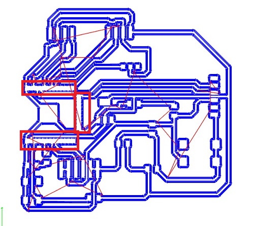
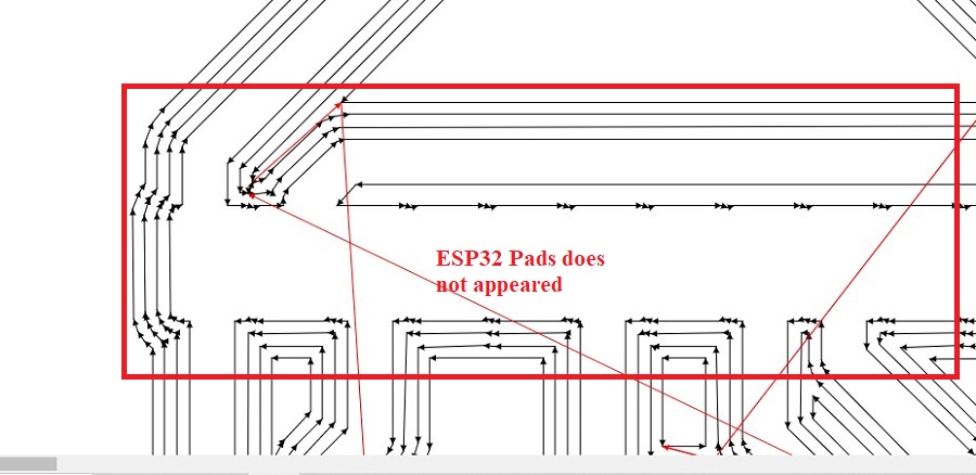
I tried for solving the problem but unable to solve the problem.M fried Pawan also faced same problem . Our fab lab manager Suhas sir guide us for solving the problem.
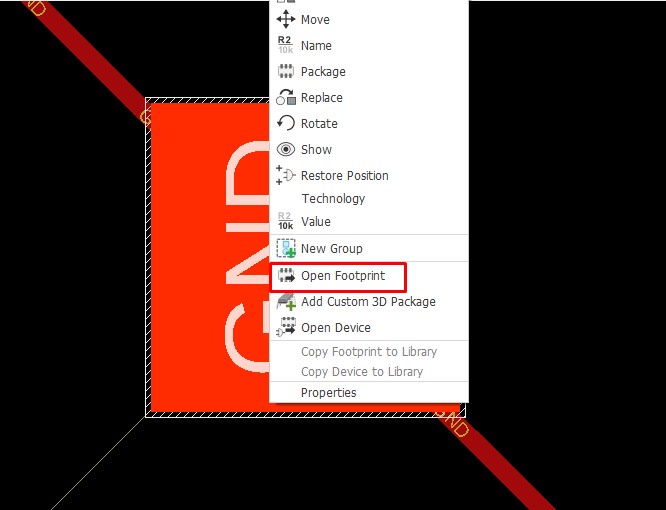
Go to the Eagle board of given design file.On board select the ESP32 and select the "open footprint".new window is opened shows the ESP32 with pad image.
Selecting the ESP 32 smd.
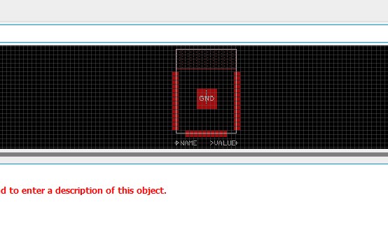
Opening new window.
On commond line write "change smd" press enter.The drop down list shows the default pad size.Select the change pad size as required.
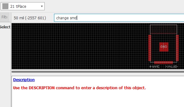
Entering in the commond line.
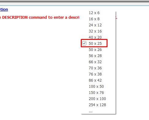
Default Pad Size.
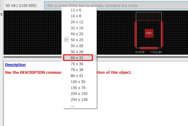
Selecting required Pad size.
Press enter, click on the ESP 32 smd pads you have to change, the pad changed as per given size.
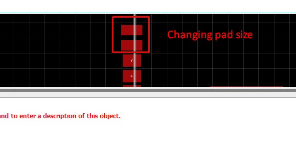
Changing the pad.
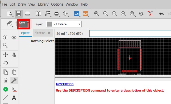
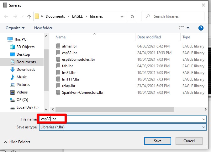
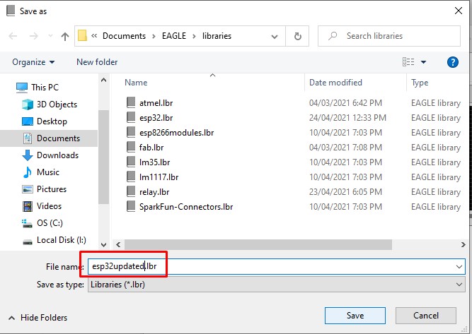
Saving the Foot print.
After changing the pads save the changes and name the file as updated in library.
After saving goto the Schematic add part,select ESP 32 wroom,add to the Schematics.Delete the added ESP32.
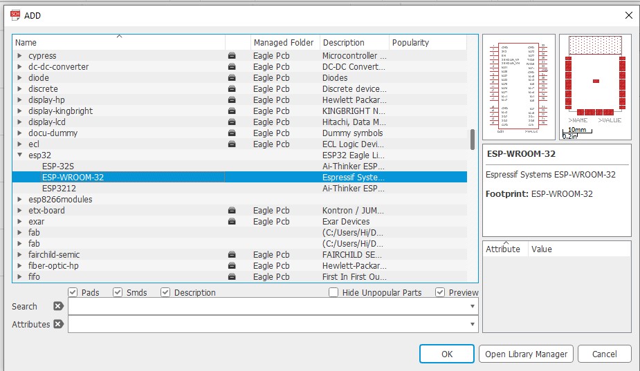
Selecting ESP32 fron add part.
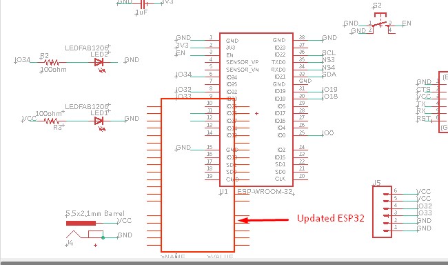
Adding updated ESP32 in Schematics.
The problem is solved as shown in the image.
The pads are appeared in tool path.
Now I milled the Board on SRM 20 machine as shown.
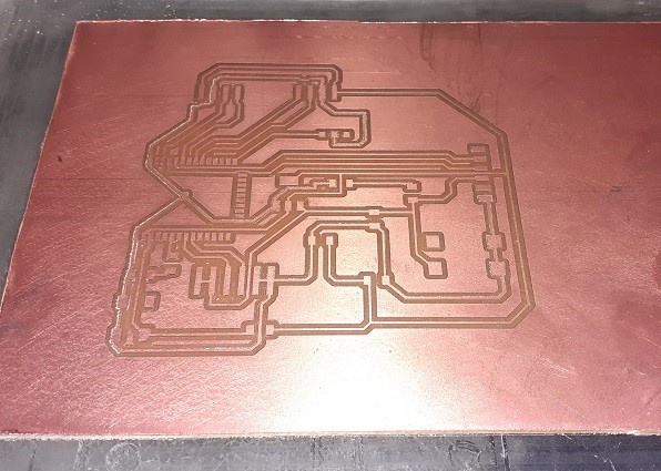
Milled the Trace.
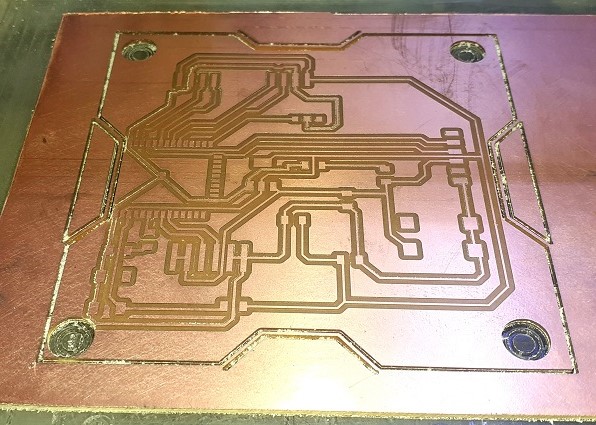
The Milled trace with cutout.
Stuffing All the Components.
The stuffed components.
Soldering the Microcontroller Board.
Final project ESP32 board.
Interfacing Microcontroller with Sensors
Interfacing BME 280 with ESP32 wroom 32D module.
Interfacing of BME280 with ESP32 wroom 32D is as shown below. the BME 280 consist of four pin out VIN,GND,SCL and SDA.The default I2C pins of ESP32 are IO21 (SDA) and IO22(SCL) so connect SDA pin to IO21 and SDA pin to IO22,VIN connected to 3V3 and GND to ground.Since there is problem in our SRM 20 milling machine i am unable to mill my ESP32 board and used ESP32 wroom 32D module.
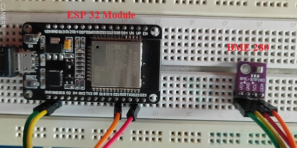
Interfacing BME 280 with ESP 32 module.
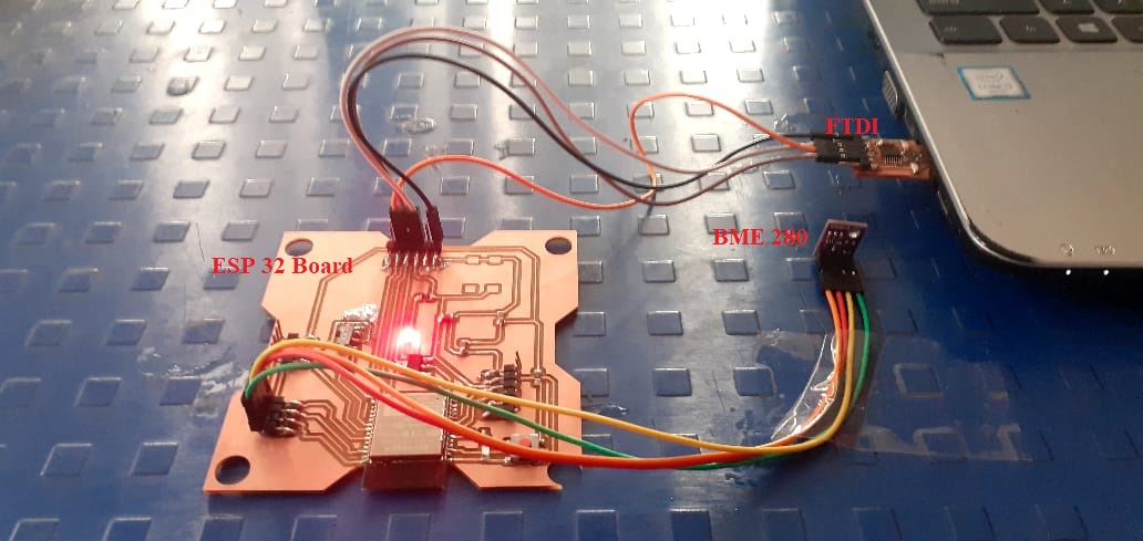
Interfacing BME 280 with ESP 32 board.
Interfacing BH 1750 with ESP32 wroom 32D module.
Interfacing of BH1750 Light sensor with ESP32 wroom 32D is as shown below. the BH 1750 consist of five pin out VIN,GND,SCL,SDA and ADDR.The default I2C pins of ESP32 are IO21 (SDA) and IO22(SCL) so connect SDA pin to IO21 and SDA pin to IO22,VIN connected to 3V3 and GND to ground.ADDR pin is used for addressing I2C interface.
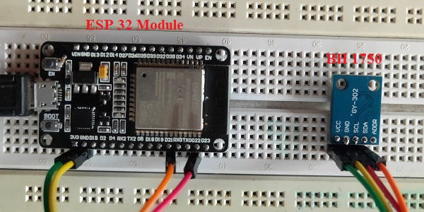
Interfacing BH1750 with ESP 32 module.
Interfacing BH1750 with ESP 32 board.
Programming of ESP32 Microcontroller.
BME280 (Humidity, Pressure and temperature sensor)
Consider the followwing program which read the values from the BME 280 sensor module (Input Device) by ESP32 Wroom 32D module and print it on serial monitor.The ESP32 code for reading Temperature,Humidity and pressure is given below.
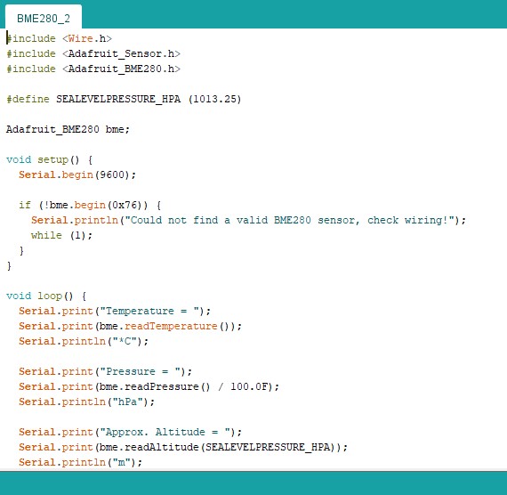
BME280 code
Reading the Values on Serial Monitor
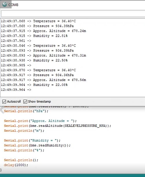
Serial monitor print.
BH1750 (Light sensor)
Consider the followwing program which read the values from the BH1750 sensor module (Input Device) by ESP32 Wroom 32D module and print it on serial monitor.The ESP32 code for reading Light intensity value is given below.
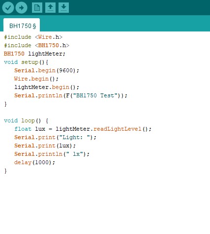
BH1750 code
Reading the Values on Serial Monitor
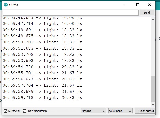
Serial monitor print.
Learning Outcomes
- In this assignment I introduced with different input devices.
- I identify the principle of different sensors.
- I used the ESP32 module,read its datasheet.
- I have design, milled and stuffed the ESP32 microcontroller board.
- I identify the different IO pins of ESP32 board.
- I used BME-280(Temperature & Humidity sensor) and BH1750(Lux module)
- Interfacing BME-280 and BH-1750 with ESP32 module and design ESP32 board.
- Programming the ESP32 for BME-280 (Temperature and humidity) and BH-1750(Lux module)sensor,checked the out put on Serial monitor.
Downloads
SAMS-Smart Azolla Multiplier System by Anand S. Tale is licensed under CC BY-SA 4.0![]()
![]()
![]()