Task to be Perform for this week
1) Group Assignment
- Probe an input device's analog levels and digital signals
2)Individual Assignment :
Design a microcontroller board
Add a sensor to a microcontroller board that you have designed
Read the data from Sensors
Learning outcomes
Demonstrate workflows used in sensing something with input device(s) and MCU board
Some Basic about the Different types Signal
What is mean by signal?
A signal is an electromagnetic or electrical current that is used for carrying data from one system or network to another. The signal is a function that conveys information about a phenomenon.
In electronics and telecommunications, it refers to any time-varying voltage that is an electromagnetic wave which carries information. A signal can also be defined as an observable change in quality such as quantity
What is the analog and digital level of the signal.

An analog signal is a continuous signal that represents physical measurements. Digital signals are time separated signals which are generated using digital modulation. It is denoted by sine waves. It is denoted by square waves. It uses a continuous range of values that help you to represent information
To know about the deatils about the analog and digital level of the signal we have reffered this LINK
So, After understanding the details about the various signals and their use, we proceed to probe an input devices to check its analog and digital level.
First we have Probe PT1000 temperature sensor to check the analog level
To check the analog level of the input devices we have used the pt1000 temperature sensor i.e bassically water proof sensor having the internal resistance of this sensor 1000 ohm at 0 degree celcius. details about this senosr mentioned in my individual assignment.

For checking the analog level of this input sensor, first we need to connect the circuit as this sensor having RTD in nature so as temperature increases the value of resistance is also get increases. We have connect the PT1000 Sensor to our microcontroller board by making the voltage devider circuit as this sensor is calibrated using 4.7Kohm Resistance, so we need to connect the same value of resistance in series with the sensor.

To ckeck the analog level we have the intrument in our lab i.e. digital storage oscilloscope, so we have probe this sensor with channel of DSO.
Initially we get the magnitute of the voltage is 1.05 Volts across the temperature sensor when we have probe the signal wire from DSO to sensor i.e the for ambient temperature.
This is an Initial signal.


Then with help of hot air gun we tried to increase the temperature so its observe that the value of voltage is increases with incresing the temperature

In this way we have checked the analog level of an input as temperature sensor.
After that we have tested the digital signal by probing the sensors i.e. BH1750 light sensor
About BH1750 (Light intensity sensor.)
The details about this sensor is given in Anand tale assignment page Here
For the group assignment task as we have to check the analog leval and the digital level of the input devices.we have check the digital level of BH1750 light sensor.
What is digital leval of the sensor.
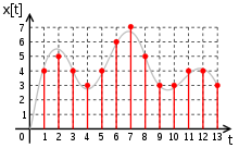
A digital signal is a signal that is being used to represent data as a sequence of discrete values; at any given time it can only take on, at most, one of a finite number of values.Simple digital signals represent information in discrete bands of analog levels.
Figure Indicate the digital signal.
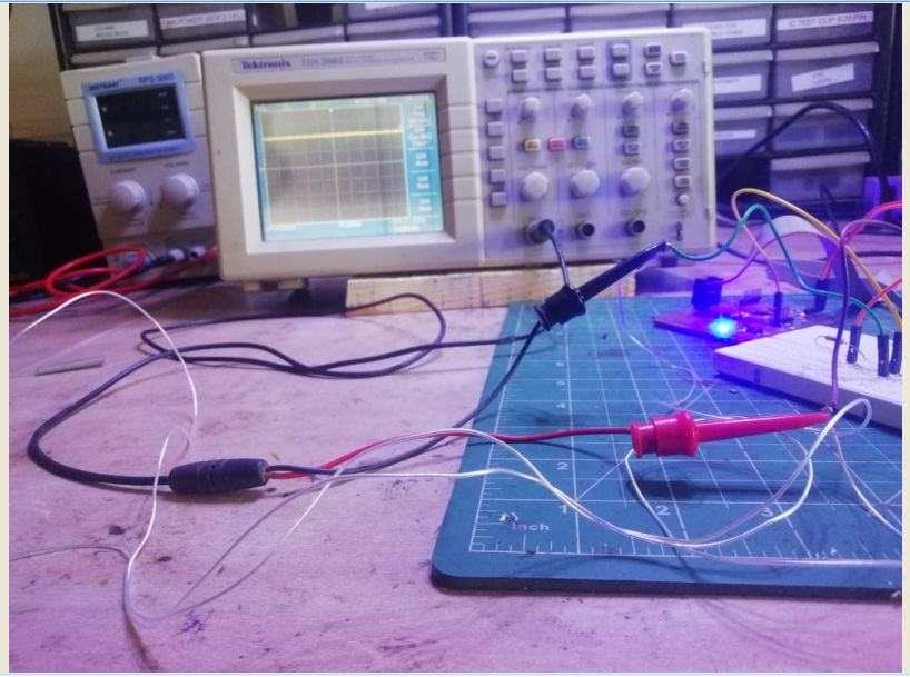
For measurement of digtal level of the BH1750 Sensor we have probe this sensor to DSO ( Digital storage Oscilloscope). As we know the sensor having 4 Pins VCC,GND, SDA ,SCL and Adder pin used for adress pin. this sensor work on the basis of I2C communication.
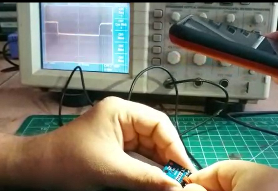
Initial we have checked the clock pulses of the light sensor by probing DSO with GND and SCL( Serial Clock pin) the results shows we have got the signal as shown in below image.it is observed that the signal we have got clock pulses in term of square wave with Equi-distance.

Here we have seen the clock pulse with equidistance , Frequency of the signal and magnitude of the signal in term of RMS Voltage.

After we have to check the digital signal for that we have connect/probe DSO with GND and SDA pin it is observed that as the light source is varying the width of pulse increases or Decreases with the intensity of light.
Here the signal is generated without light observed that the width of pulse is reducing in nature

When we apply the light on the sensor the width of pulse is increases.