Week 12 and 13 - Mechanical Design and Machine Design
week 6 and produced in Week 8.
In our group assignment, We showed, how we tried to build an CNC HotWire-FoamCutter. I was mainly responsible for the 3D-Model and the wiring.
Idea
The Idea was to make a HotWire-FoamCutter which was initially intended to run on the Board i made in Week 8. This was also a great opportunity to test if the board is capable of Driving the Drivers for the Stepper Motors. The cutter needed a Z-Axis to lower and raise the Hotwire and also an X-Axis to move the Wire in and out the Stock. The Y Axis on the other hand should be able to rotate the Stock, so that we can cut almost any shape from just 2d to roundish objects.
3D-Modeling V1
Frame
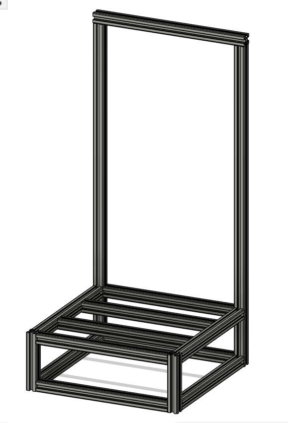
The Frame was build out of 2020 Aluminum Profile with a 5mm Slot, because we had this on hand. The dimensions where chosed based on pre cut Profiles laying around to reduce the number of cuts to make. We went with a base dimension of 630mmin heigth and 300mmx300mm as a square base. For joining the profiles, we went with a technique called Blind joints.
Bildjoints
more detailes at lysander's Documentation.
Blind Joints is a technique that takes advantage of the profile's internal slot. In our case, we tapped the ends with an M5 thread and used M5x16mm screws on one profile. On the mating profile, we made a 5mm hole for a hex key to pass through. During assembly, the screw head is slid into the slot and then tightened using the hex key through the 5mm hole. This creates a clean, strong joint without the need for external brackets.
X-axis
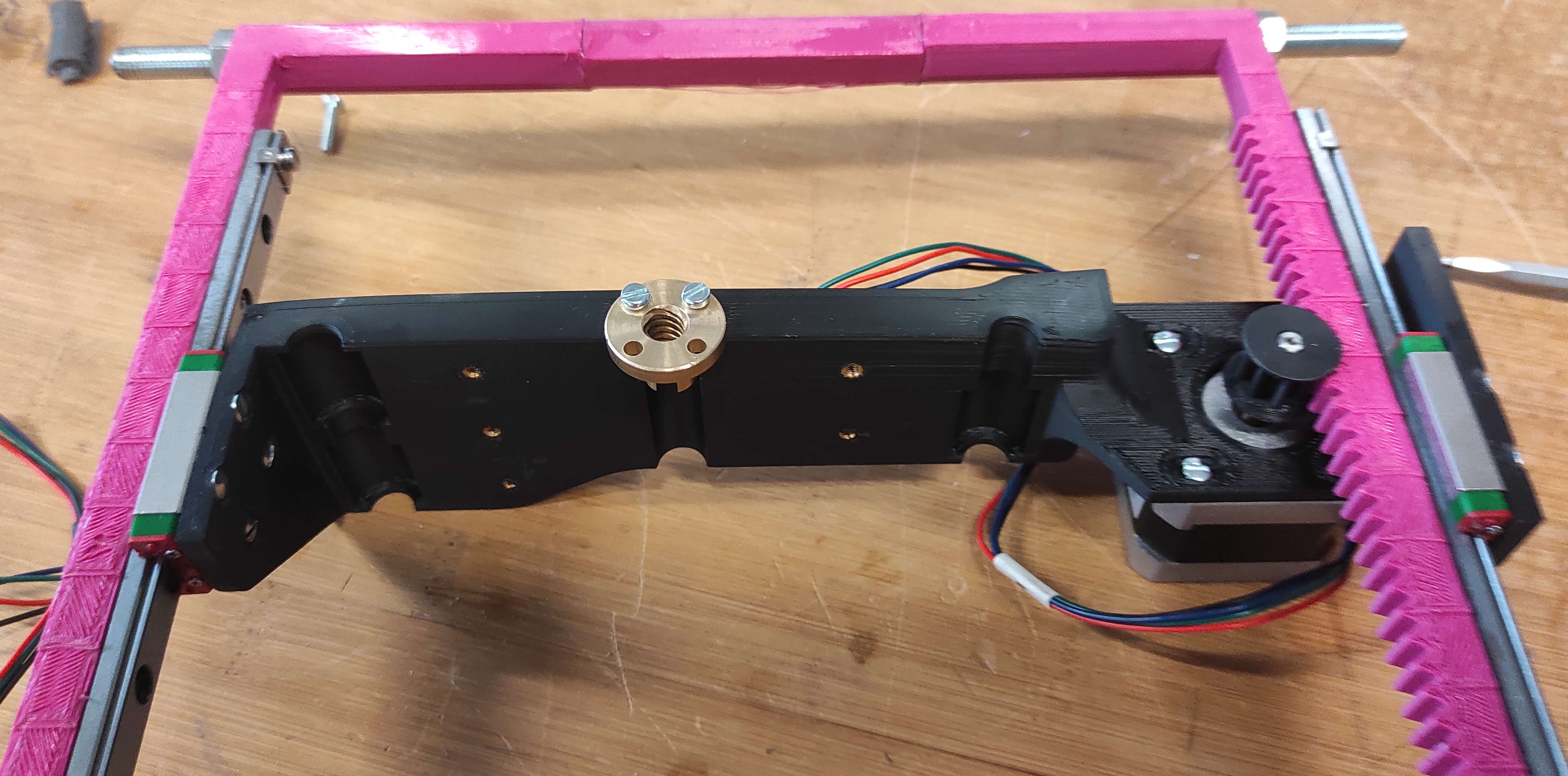
For the X-Axis for stability we used mainly the MGN9C Rails and a 3d "bow", which we needed to print in 3 Parts to fit it on our Printers, because even the largest Printer(except the BigRep, which's print quality wouldn't be fine enough) in our Lab were to small for the not splitted part. for At the end of the "bow" we added 60mm long carbon fibre rods, as insulator for Heat and also for the power. The rack is 9mm in width, so it fits snuggly with the MGN9 Rail. For the Pinion, we made the gear part 10mm to have so wiggleroom and also capped the ends, so it wont slide off the rack.
Rack and pinion
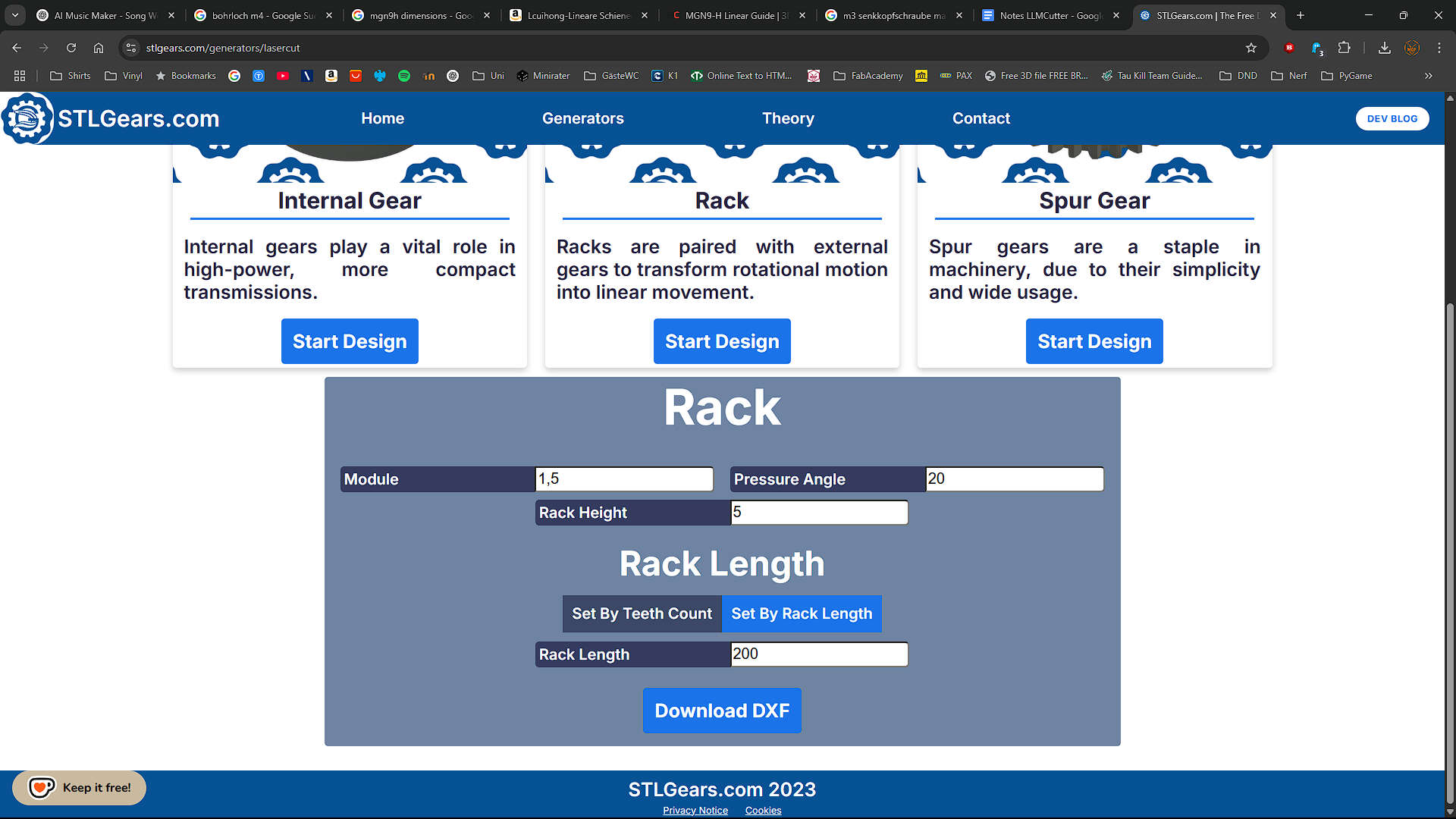
For the Rack and Pinion i used the DXF generator on stlgears.com and then imported the dxf into fusion and extruded the profile to have Rack and pinion.
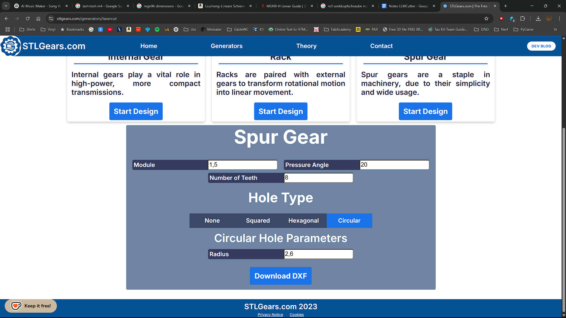
Pinion Settings: Spurgear with a module of 1.5mm, a pressure angle of 20° and 8 teeth. Circular hole with 2.6mm radius
Rack Settings: Rack with a module of 1.5mm, a pressure angle of 20° and 5mm rack heigth. Length is 200mm
used Models
For reference while modeling the X-Axis, I used the MGN9-H Linear Guide by Lehaiver
Y-axis
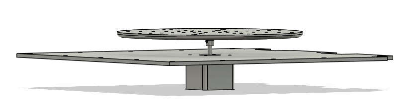
The Y-Axis is pretty simple. Its just the Top Cover where the motor is attached to and then the Rotor Table Placed on the Motor
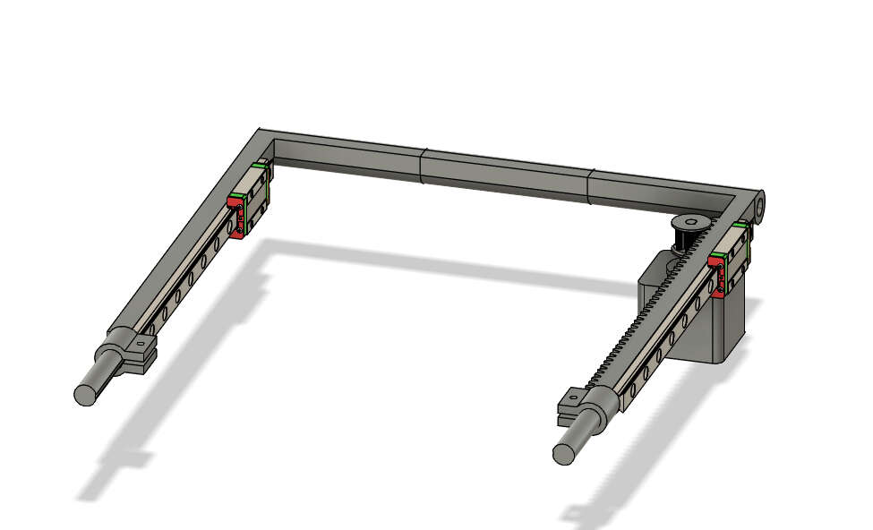
Z-Axis
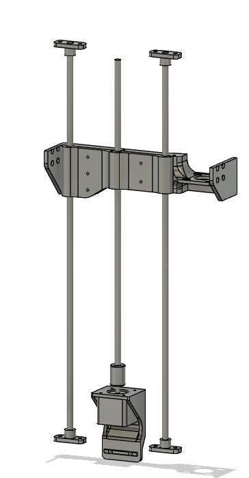
We started with the Rodholder and duplicated them to the respected places. The right rod is shifted to the left, to make space for the X-Motor. The Z-Motor is held by a printed part located directly at the middle between the rods, where also the the Leadscrew is Attached sccrew. The carrier houses 3 LM8UU Bearings, two placed on the left and one on the right rod. on the outer sides the MGN9-H Carriers are attached so in that case they are our stationary part. The Xmotor with the XPinion are located between the right MGN9 Rail and the right Z-Rod.
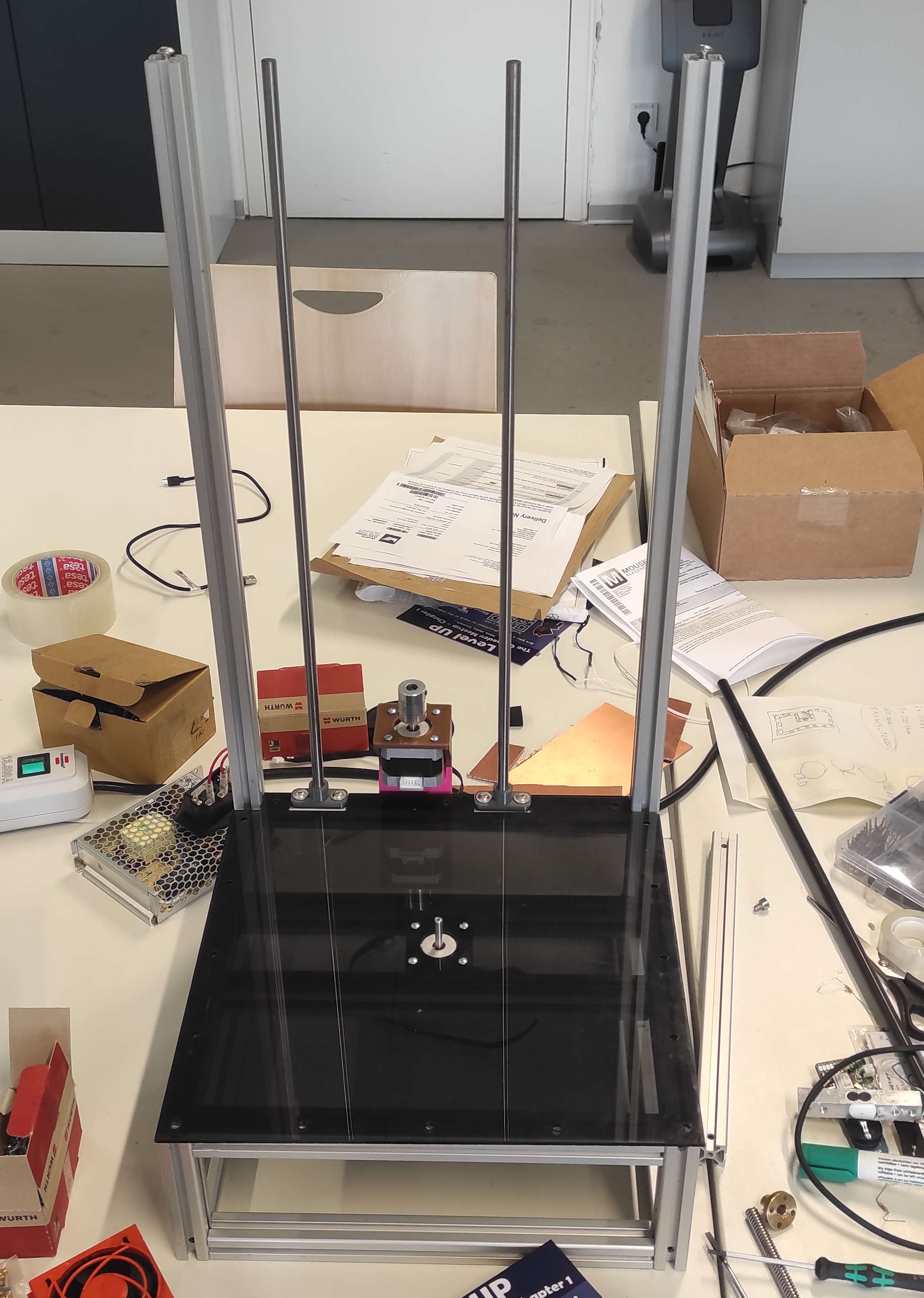
Completed 3D-Model
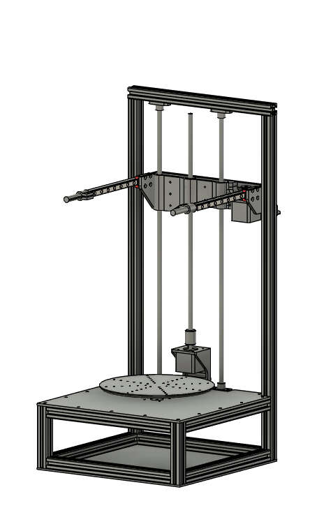
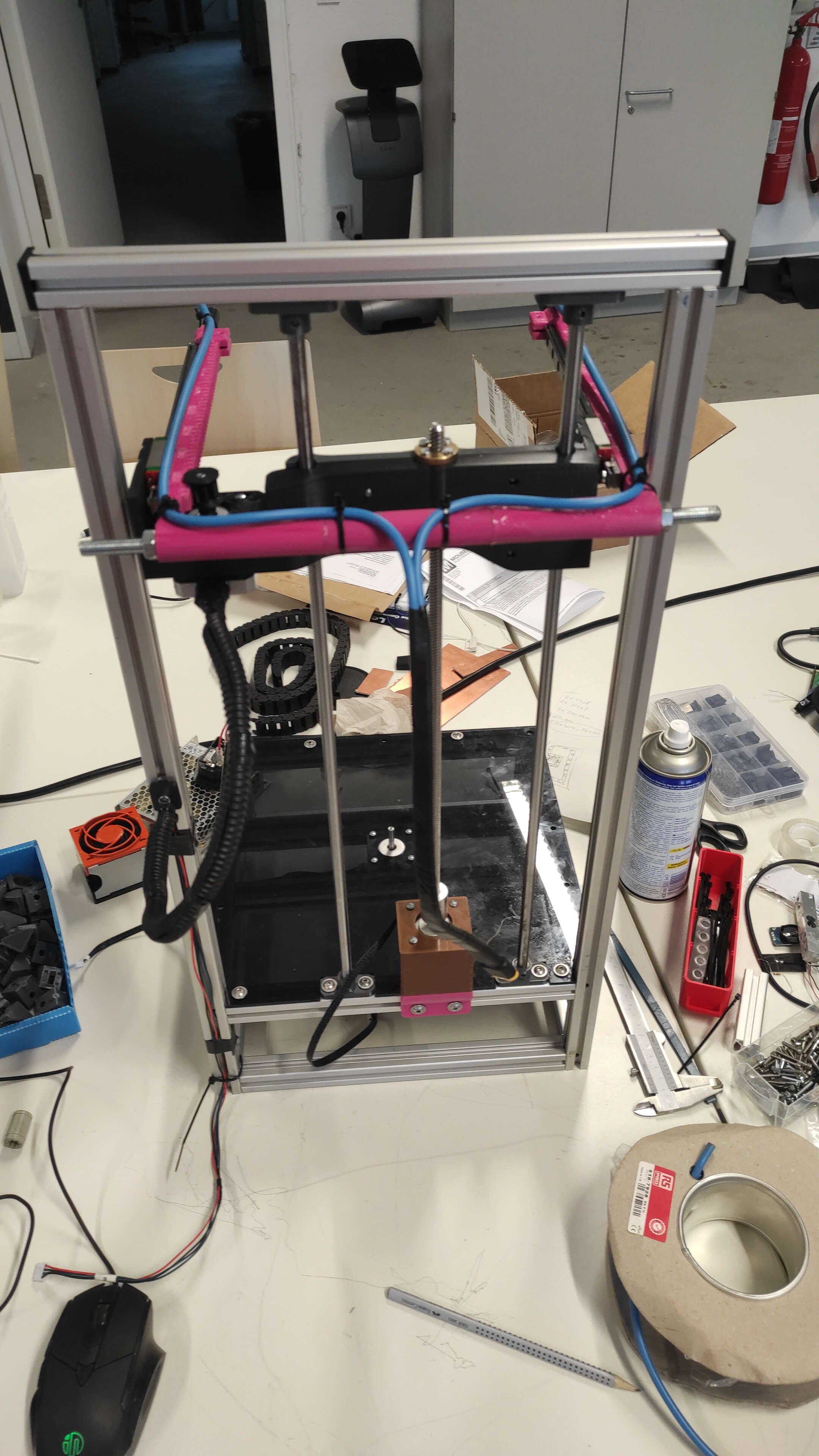
here you can see the whole 3D-Model
Downloads
F3D archive production filesAssembly
Cutting the MGN9 Rail
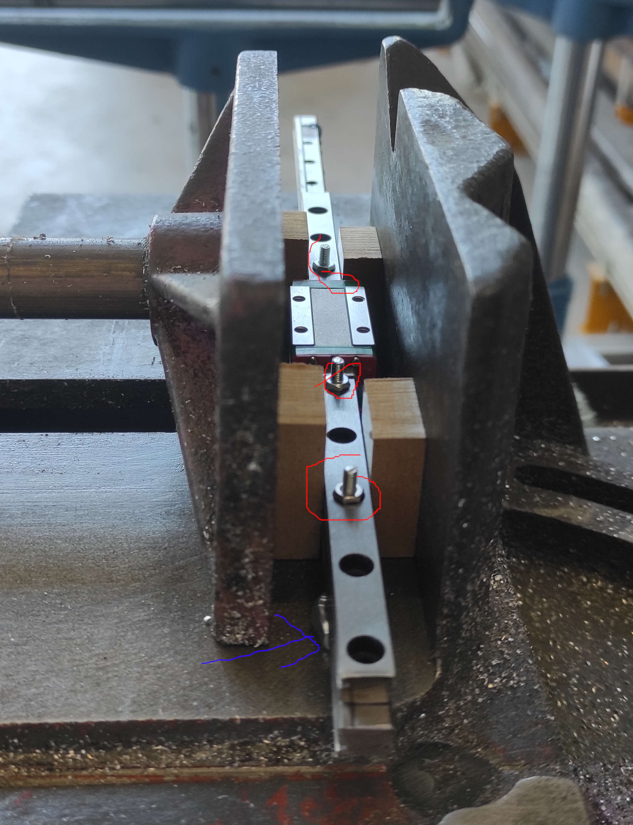
We had one precut MGN9 Rail with 200mm on hand, so that we needed to cut the other to the same length with the same hole Pattern. For that we screwed the two rails together with some m3 screws and nuts(marked red), clamped them with some wooden blocks on the side, so that the carriages where able to move freely and are not pressed. To rise the rails from the bottom we used 2 M8 nuts, one marked blue in the front and one is in the back, which is not vissible. we used the top rail as guid for the band saw. after the first cut was done, we turned the rails around and cut the other side.
Frame
Shown in lysander's Documentation.
Profiles:
- 2 x 610mm
- 2 x 110mm
- 10 x 260mm
- 1 x 300mm
other parts:
- 14x M5x16 Socket Button Screw
X-Axis
- Print the Parts
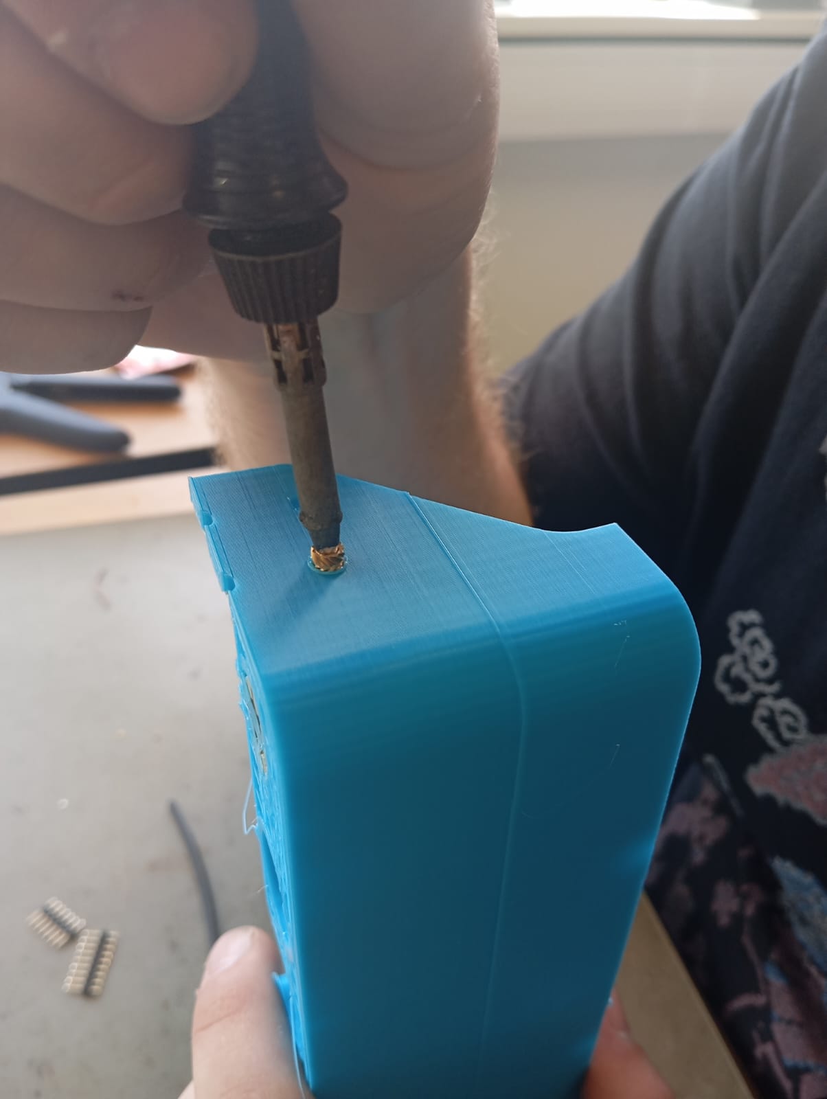
- Melt heat inserts into both sides of the XCarrier to screw the Rail onto. like this:
- Screw the Rails to the sides
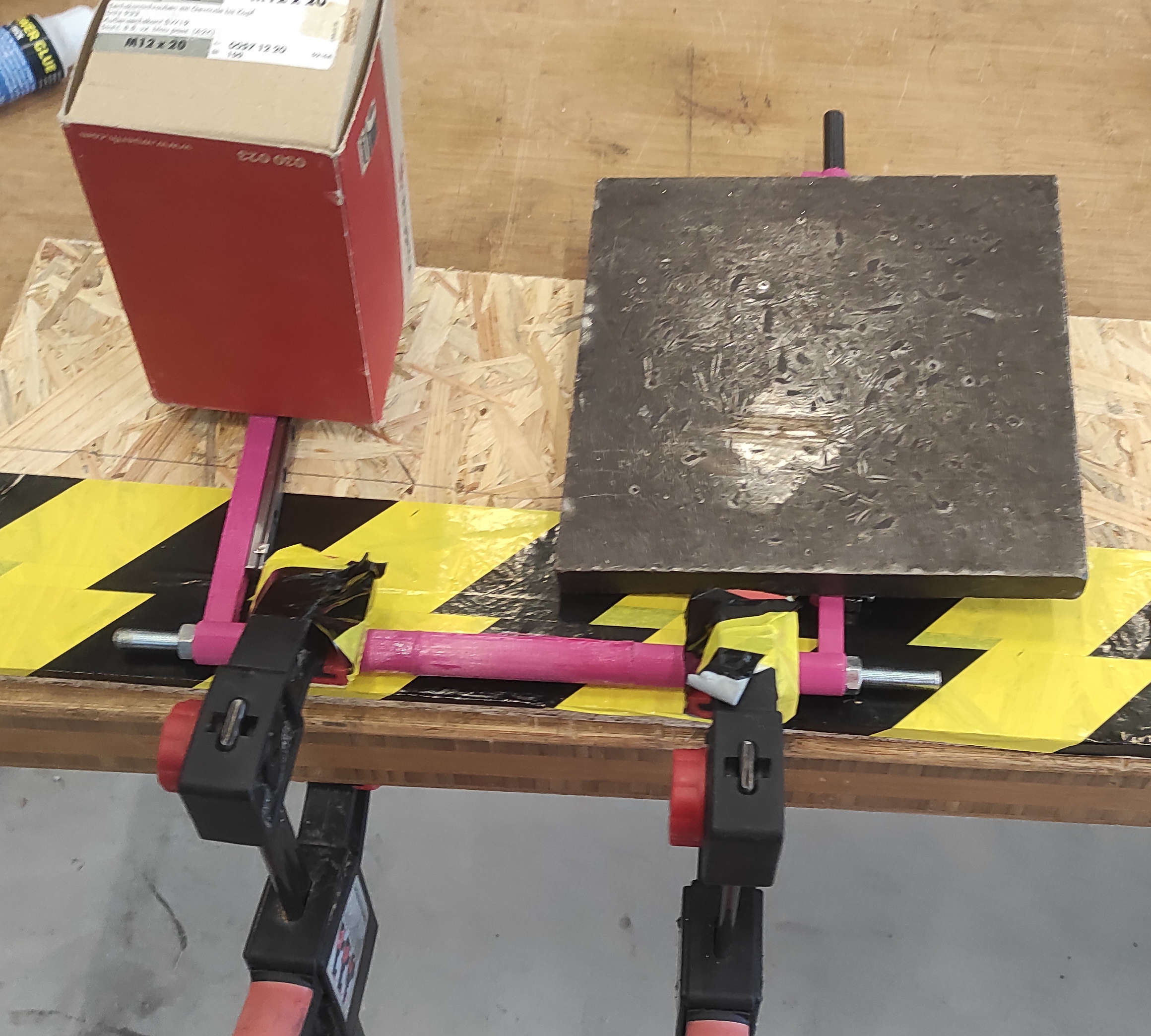
- Glue all 3 XCarrier parts together. I used 2k Epoxy to glue everything together and a 8mm rod with Nuts for stability
- Screw the MGN9-C Rails onto the XCarrier(and if not already done like it was already by us, put the carriage onto the Rail)
printed Parts:
- 1x XCarrier L
- 1x XCarrier R
- 1x XCarrier Mid
other Parts:
- 2x MGN9R 200mm linear rail
- 2x MGN9H Carriage
- 20x Ruthex RX-M3x5.7
- 20x M3x10mm Socket Cap Screws
Y-axis
The Y-Axis was straight. . We just printed and laser cut all pieces, then screwed the Motor to the TopCover(with the Socket cap screws) with the cable orientating to the rigth(blue Arrow) and screwed it with the 4 (red) marked holes to the Frame with the m5 nuts and Screws.
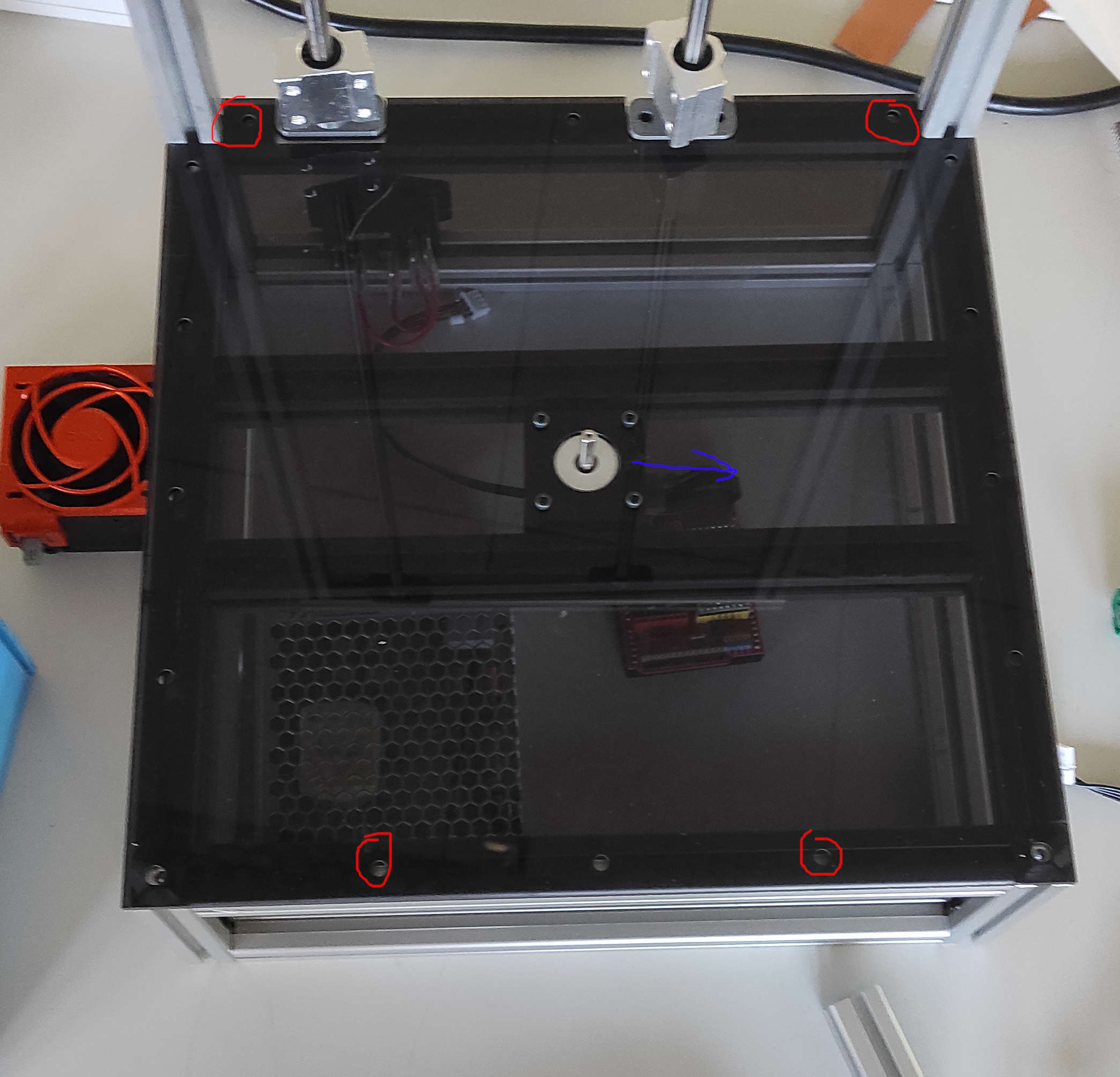
last step for the Y-Axis was to put on the RotorTable
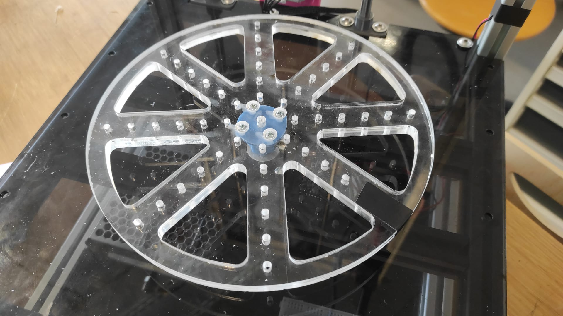
We have a different Rotor Table, more information later in the documentation
printed/lasercut Parts:
- 1x TopCover (4mm PlexiGlas)
- 1x RotorTable
other Parts:
- 1x Nema17 Motor
- 4x M3x8mm Socket cap screws
- 4x M5 Slot5 SlotNut
- 4x M5x10mm Socket Button Screw
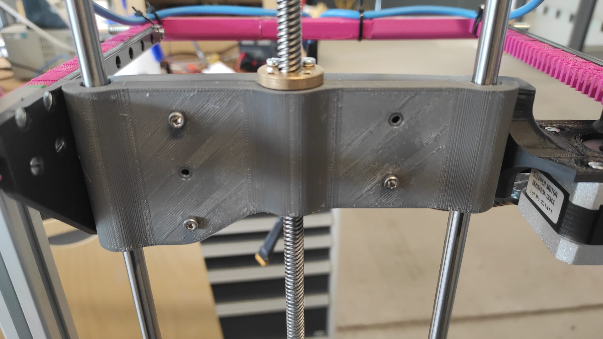
Z-Axis
- Print the Parts
- Removed the top Frame Piece
- Screw the bottom ZRHolder into the notches from the TopCover. Also Insert the ZRods.
- Assembled the ZassHolder with the motor(with the Socket cap screws), attached the flex couppling to the motor and mounted the Assembly to the frame in the middle between the the two ZRods.
- inserted 5 Heat inserts into the Z-CarriageA
- Screwed the X-Axis to the Z-CarriageA with the countersunk screws.
- placed the XPinion onto the rack before screwing the second motor to the Z-CarriageA. Putting the XPinion on the motor before screwing the motor to the Carriage wouldn't Work
- screw the Leadscrew nut onto Z-CarriageA wit the first 2 M3x20mm Screws
- put 2 LM8UU Bearings onto the left and one on the right Zrod.
- screwed the Leadscrew into the nut
- placed the bearings into the corresponding places in the Z-CarriageA
- Close the Z-Carriage with Z-CarriageB(M3x16mm Socket Cap Screws) also screw the last 2 M3x20mm of the Leadscrew nut to the Z-Carriage
- Secure the LeadScrew in the Flex Coupling
- Put the top Frame piece back and secure the
printed Parts:
- 1x XPinion
- 4x ZRHolder
- 1x ZassHolder
- 1x Z-CarriageA
- 1x Z-CarriageB
other Parts:
- 2x Nema17 Motor
- 8x M3x8mm Socket cap screws
- 1x 8mm Leadscrew plus 1x nut
- 4x M3x20mm Socket Cap Screw
- 8x M3x8mm countersunk screws
- 3x LM8UU Linear Bearing
- 5x Ruthex RX-M3x5.7
- 5x M3x16mm Socket Cap Screws
- 2x M5 Slot5 SlotNut
- 2x M5x10mm Socket Button Screw
- 1x 8mm 4way Leadscrew 400mm length
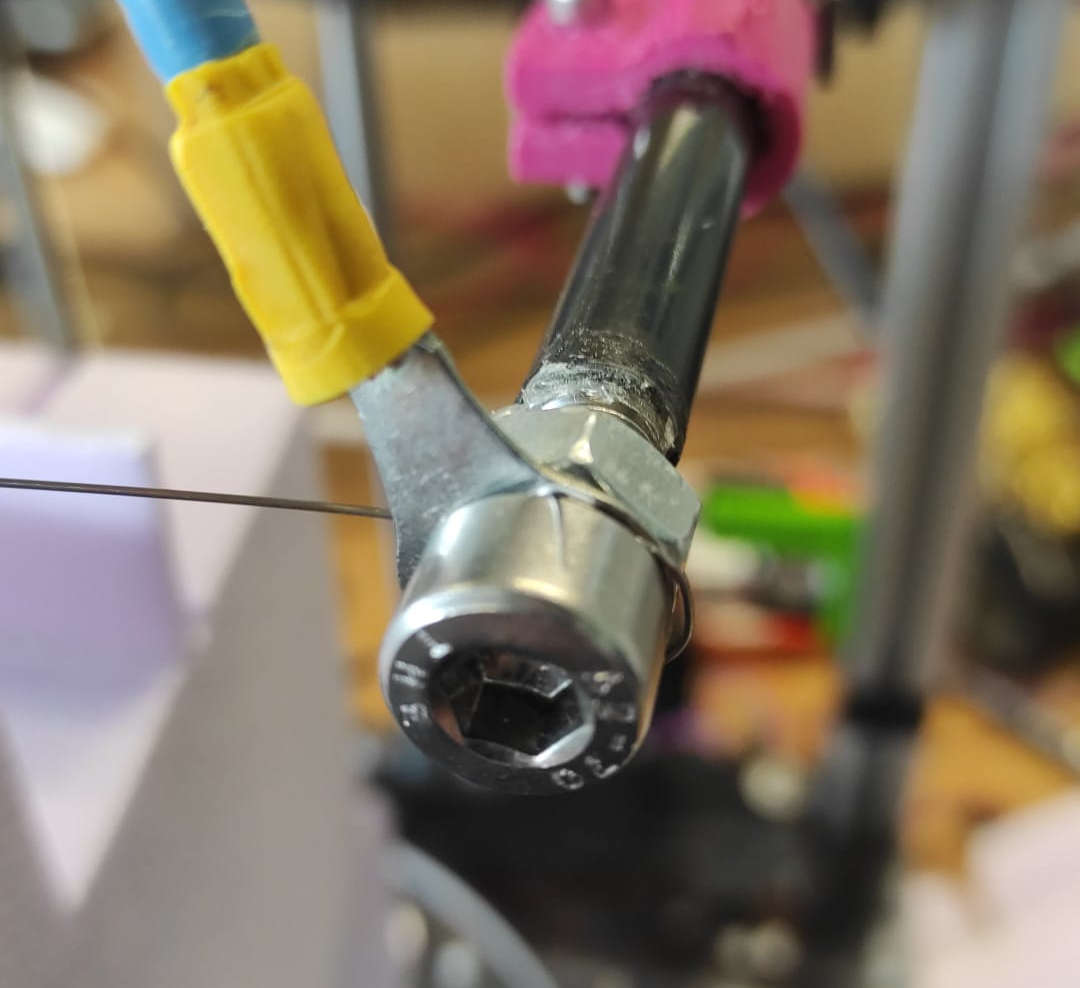
Cutting Wire
We started by Crimping the 9AWG Wire with the cable lugs. Then putting them onto the m8 Screws with nuts. These Srews were then glued with 2k Epoxy into the Carbon rods with 20mm thread exposed.
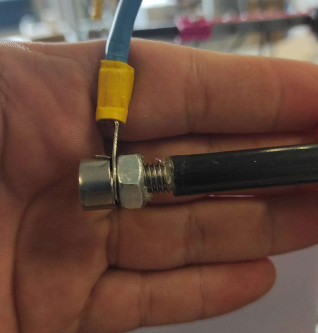
After drying, we inserted the tubes into the tube Holder and secured them with the M3 Nuts and Screws. The last step was to put the Cutting Wire. 0,5mm V2A Stailess Steel wrapped around the screw and then secured with theM8 Nut.
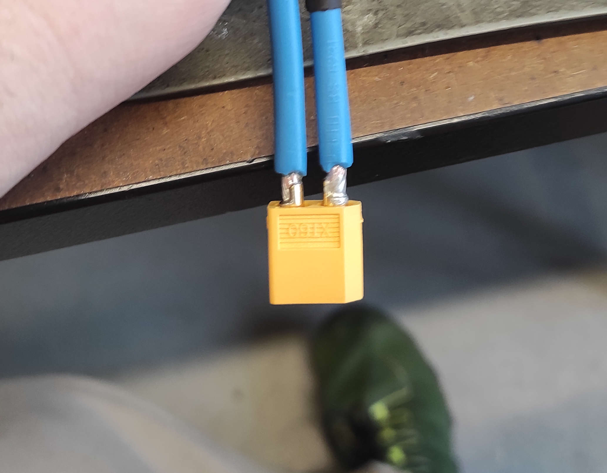
Now we are going to the back. We needed to solder a connector, so we can move the hole assembly easy and handle the Test setup easier. We used an XT60 connector usaly used to connect lipo Batterys to applications where a high powerdraw occures. We used smaller Shrinking Tube to cover the soldered connection and a bit larger one to tigthen up the backside for cable management. With zipties, we did the cablemanagement along the "Bow"
other Parts:
- 2x M8x40mm Screws
- 2x M8 Nuts
- 2x M3x20mm Screws wih nuts
- 2x 10mm Carbon Tube with 60mm length
- 9AWG/6mm^2 Wire
- 2x 6mm^2 loop cable lugs with 8mm hole
- XT60 Plugs
- zipties
- Shrinking tube
Changes in the Prototype
What didn't occure in the 3D-Model:
- The Endswitches
- cablemanagement
printed Parts:
- 1x CableHolder
- 1x ZSwitchHolder
other Parts:
- 2x Endwswitch
- 3x 2.5mmx10mm wood screws
- Corrigated Tube 15mm InnerDia
- 2x M5 Slot5 SlotNut
- 2x M5x10mm Socket Button Screw
- M8 Nut
LimitX
First step was to create a Trigger. We cut it out of a piece of 12mm birch multiplex with the rough dimensions of ~25mm by ~25mm, then drilling an 8mm into the middle and fasten this to the stabilizer Rod of the "Bow"
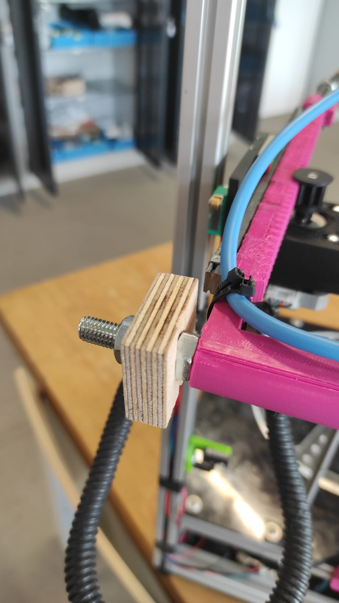
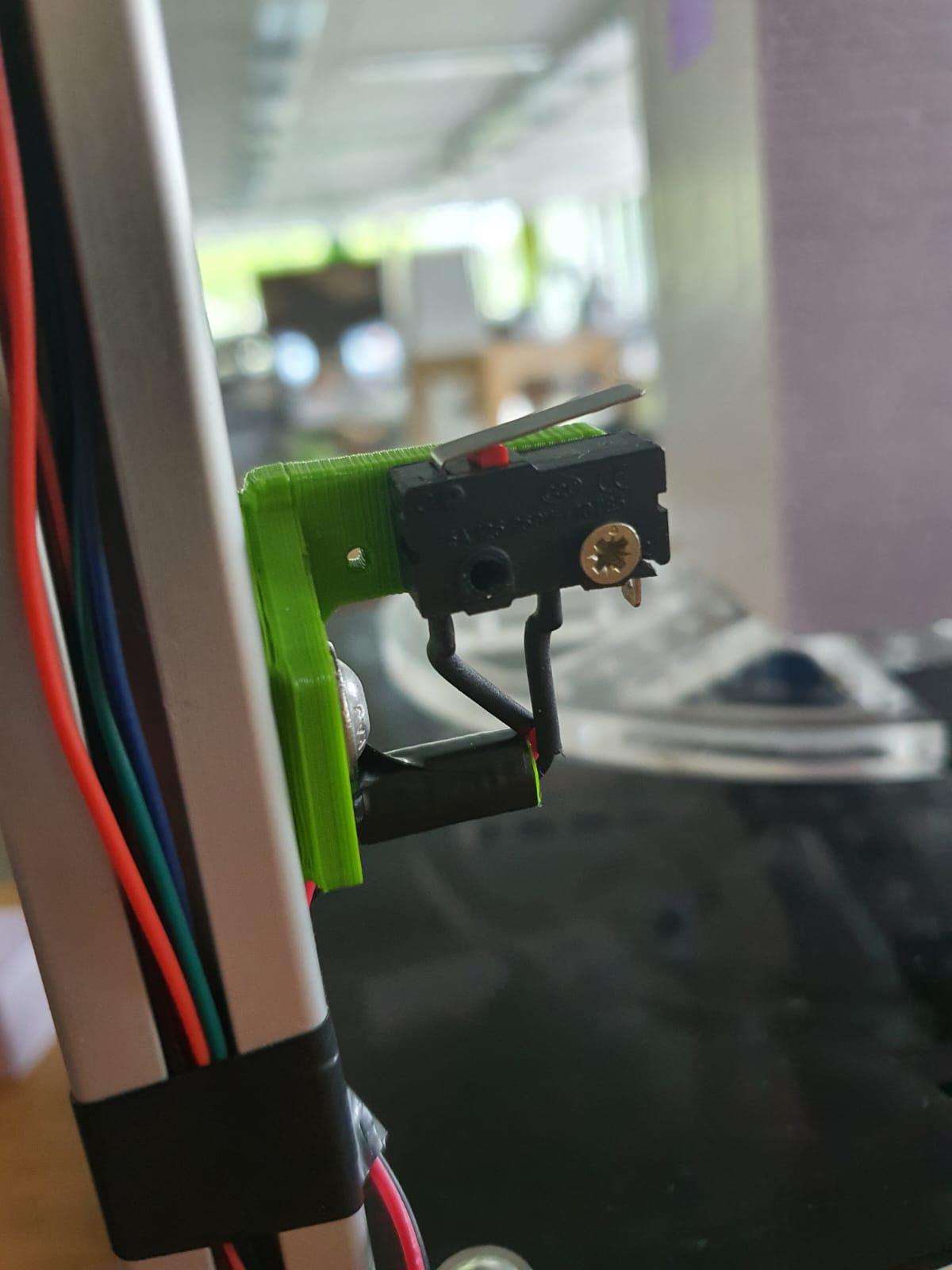
for the X-LimitSwich We just eyballed the position on the Z-Carriage. At the poínt it looked good and it would be triggered by the Rod with an the wooden extension, i marked the holes, and drilled them with a 2mm Drillbit Last Step was screwing the X-LimitSwich with two woodscrews into the drilled holes.
LimitZ
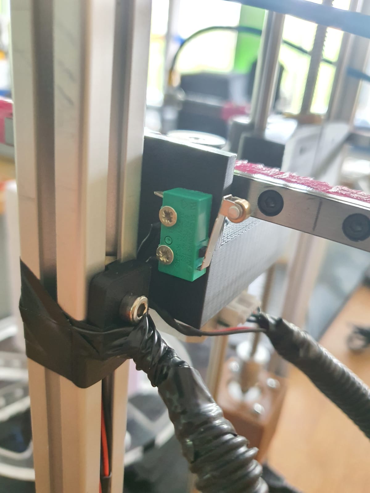
Leen edited my CableHolder(which you also need later and is not in the production files) as holder for the Z-Limit Switch. Which is placed on the inside and motor side of the frame, so that after screwing the LimitSwitch(which two wires on NO and G are soldered to) with one of the wood screws to the holder, is able to be pressed by the motor on the Z-Assembly. The heigth was adjusted by turning the Leadscrew until the Z-Carriage nearly hits flex-coupler. The Switch Holder was screwed at the point, where the limit Switch was pressed.
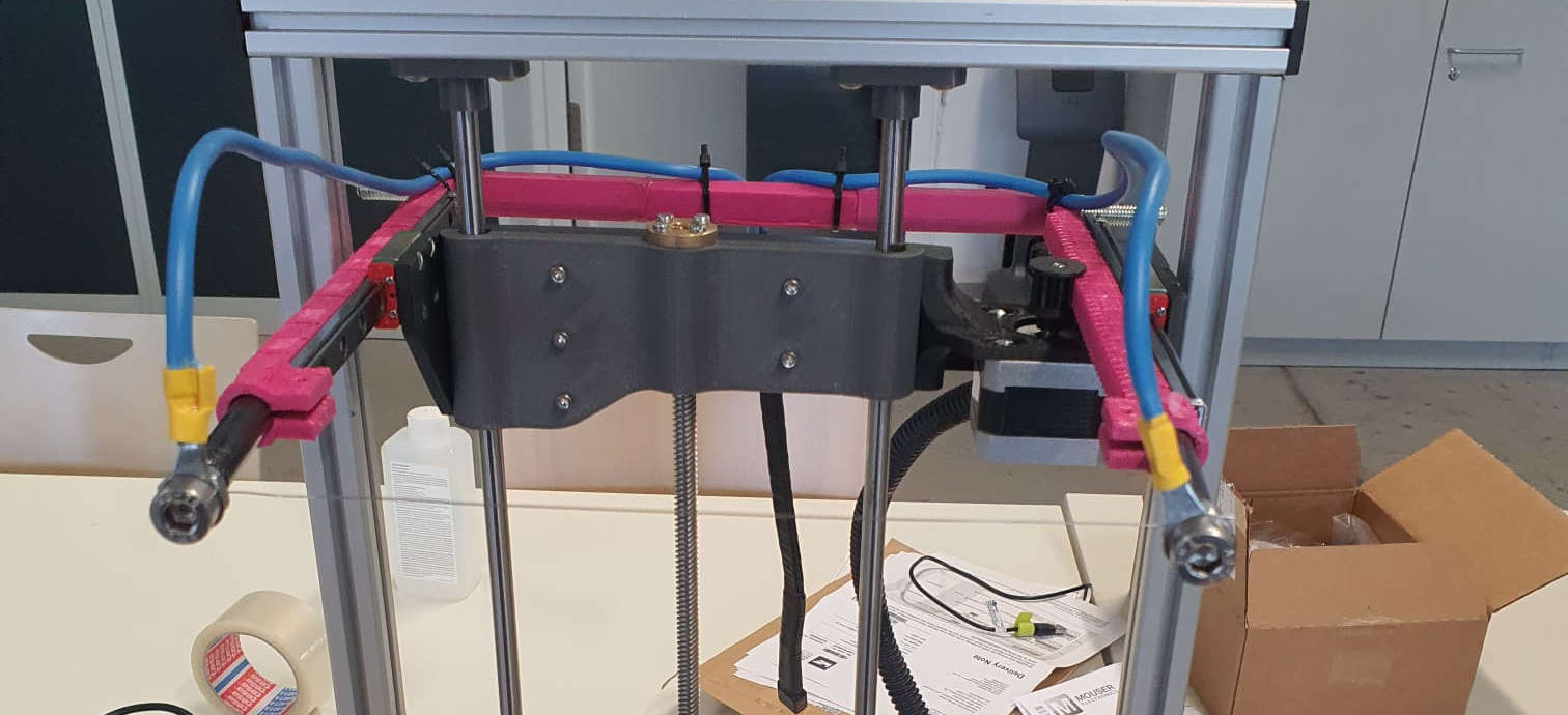
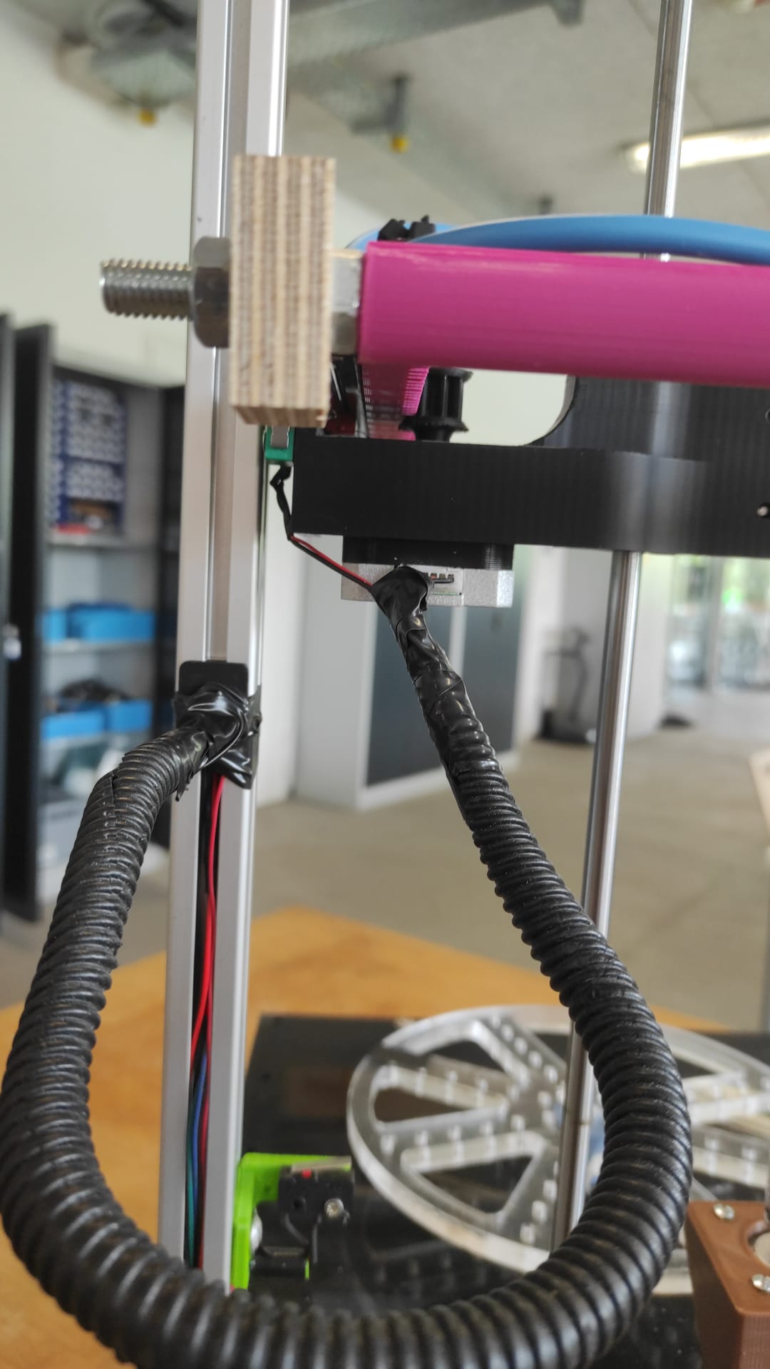
cablemanagement
This also was an easy Task. We mounted the cable holder in the middle of the travelway of the Z-Axis(with the m5 Screw) Then Routed the X-Limit and X-Motor Cables through a piece of Corrigated Tube with 15mm inner diameter for cablemanagement to the Cable Holder and secured everything on both sides with electrical Tape. the wires then were in the channel to hide and again used electrical tape for securing. We also routed the Cable from the Z-LimitSwitch through the caneel to the bottom compartment.
Wiring and Electronics
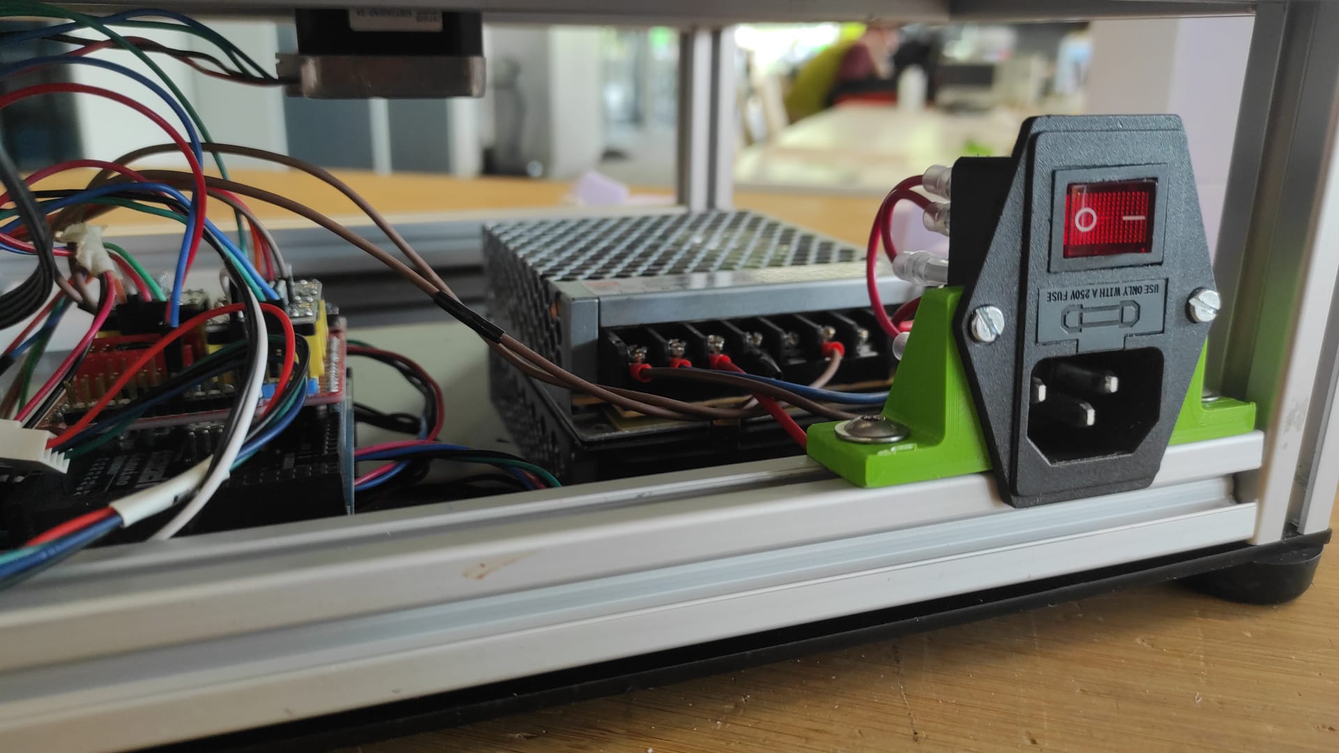
12V
For Connecting 12V we first placed the 12VPSU onto the BotCover and marked the two bottom Screw holes of the
PSU, drilled them as 3mm holes and screwed the PSU onto the BotCover with the M3x8mm screws.
Now the IEC Powersocket. This was attached to the mounts with the M3x20mm and nuts, which then mounted with
the M5 Screws to the Profile near the PSU.
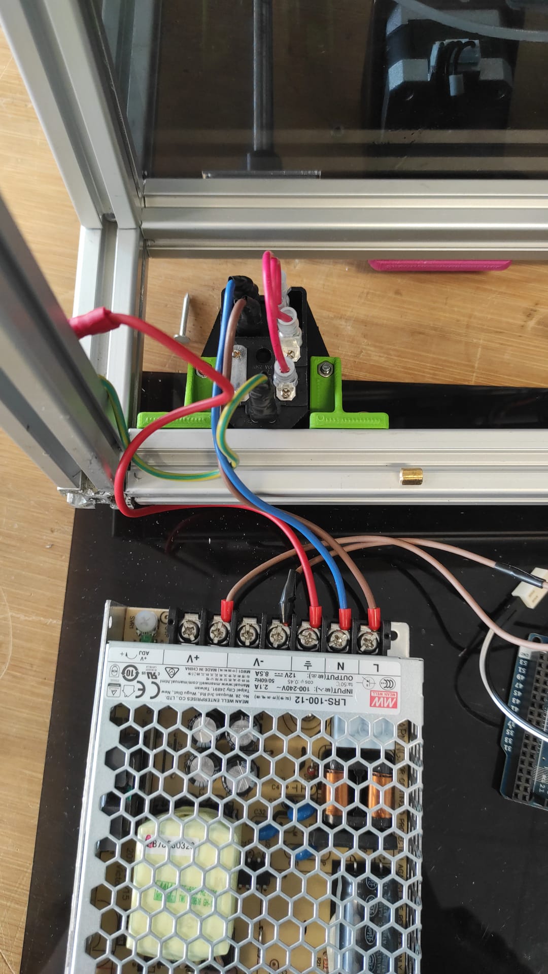
Both PSU and Powersocket in Place, we needed to start wiring. We crimped spade connectors to one side of the
N and L cables and put them onto the 2 top connectors of the Switch from the Powersocket. a PE Cable was
also crimped on one side this way and put to the open Connector on the actual socket. The PE Cable got a
loop cable lug and was then connected with the red wire to the frame with the m4 screw and Slot nut. The red
cable(used as PE) and the L and N cables where the attached to the corresponding terminals on the PSU.
On the 12V+ terminal We used a brown cable and on the 12V- terminal a black marked brown cable(we don't had
cable in different color with same awg sufficient for the needed power on hand.)
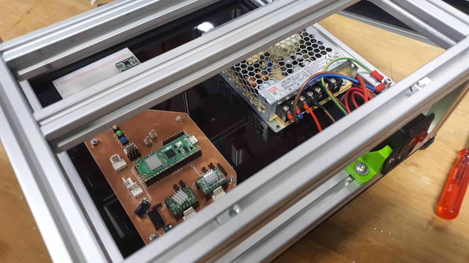
Using Mikas Board
First attempt was to use Mika's Board, because it had already 2 Slots for Stepper Drivers and also connection for 2 Limitswitches. After 2 hours of trying, we decided to switch to the CNC shield, which we already used for testing and setting the Current Limit of the Stepper Drivers for each Stepper, so we now it works.
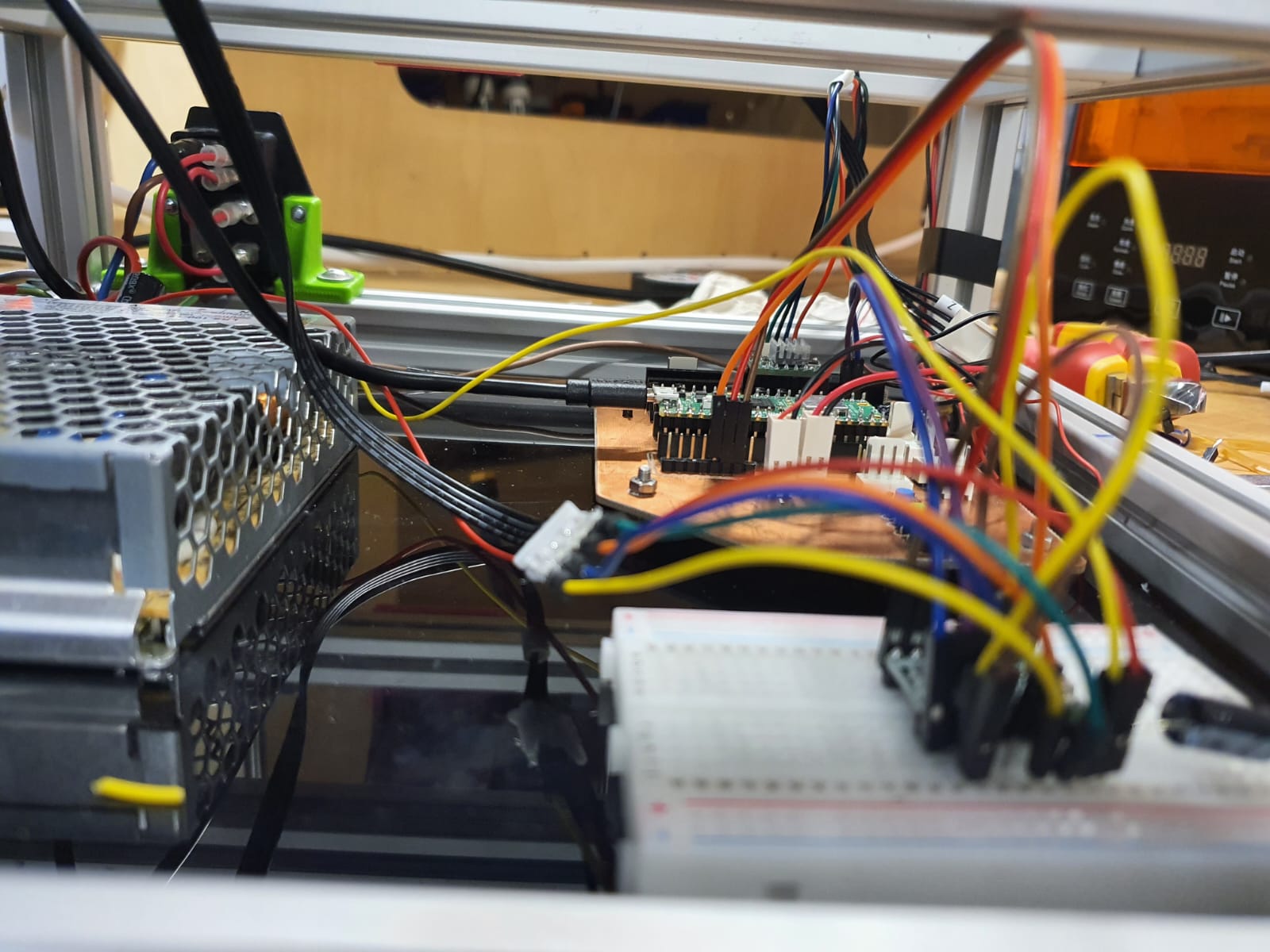
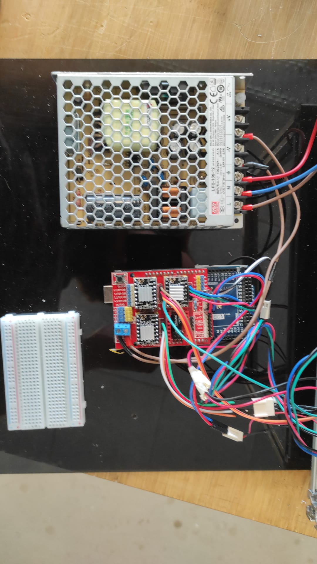
Using the CNC Shield
Connecting 12V to the CNCShield was done by connecting the brown and black mared Cable to the blue marked terminal. The TMC2100 drivers were put with the eneable pin to top left into X, Y and Z and the corresponding Motors rigth next to them. we also put Jumpers(marked green under the drivers) to set microstepping to 1/2. The Z and X LimitSwitches where connected to the corresponding + on black and white
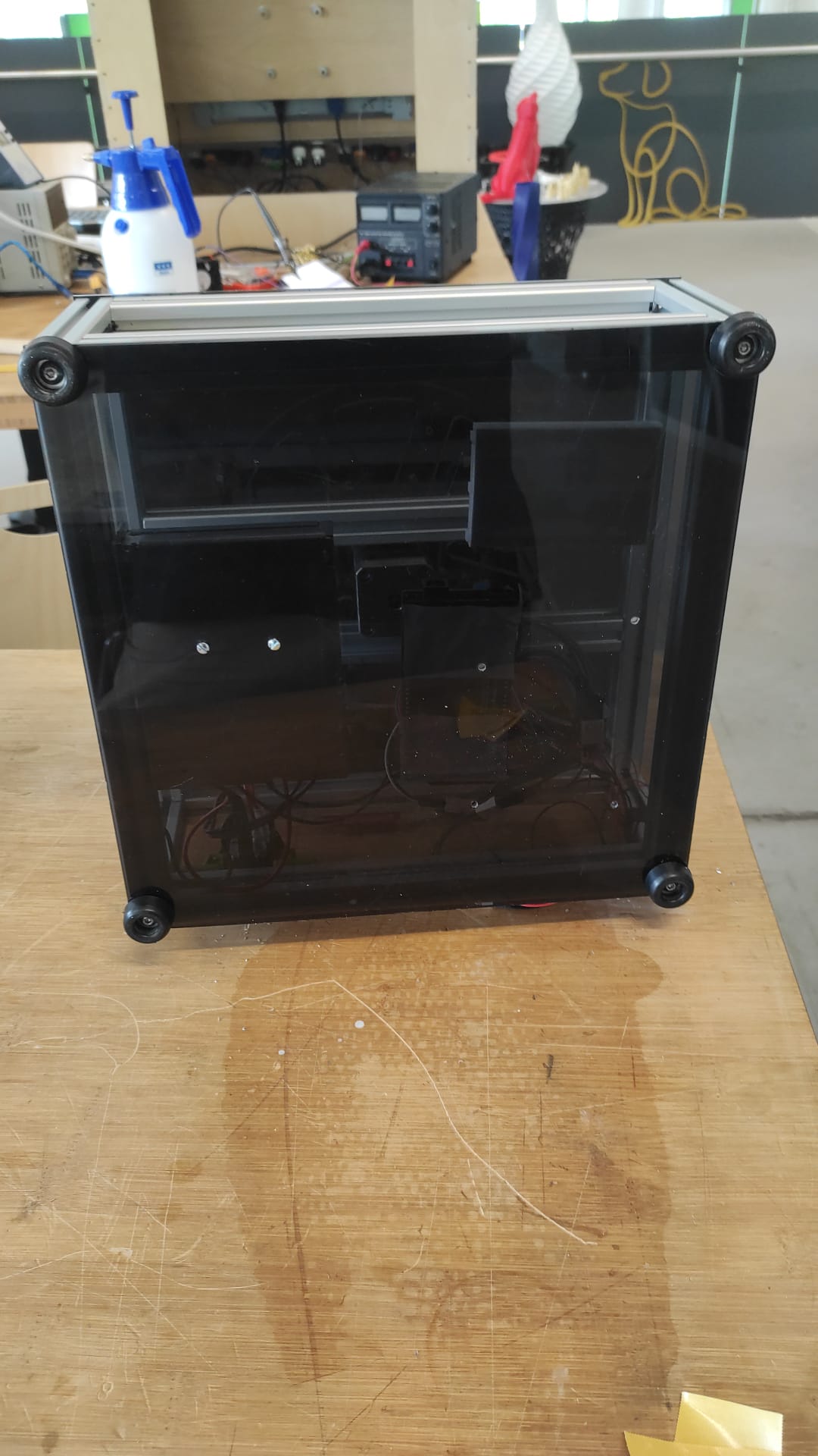
Cover It Up
Here we tapped the 4 corner profiles with m5 tread and screwed the BotCover with the Rubberfeet and 4 M5x10mm Screws to the Frame
lasercut Parts:
- 1x BotCover (4mm PlexiGlas)
- IEC power socket 2020 mount
other Parts:
- 1x Arduino Mega
- 1x CNC Shield
- 3x TMC2100 SilentStepStick Driver
- 1x IEC power socket
- 1x Meanwell 12V 8.5A Powersupply
- 2x M5 Slot5 SlotNuts
- 6x M5x10mm Socket Button Screws
- 2x M3x8mm Socket Cap Screws
- 2x M3x20mm Socket Cap Screws with nuts
- 4x Rubberfeet with 5mm hole
- 1x M4 Slot Nut
- 1x M4x8mm Socket Cap Screw
Coding
Shown in Leen's Documentation.