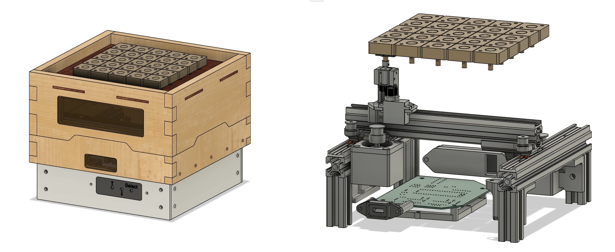
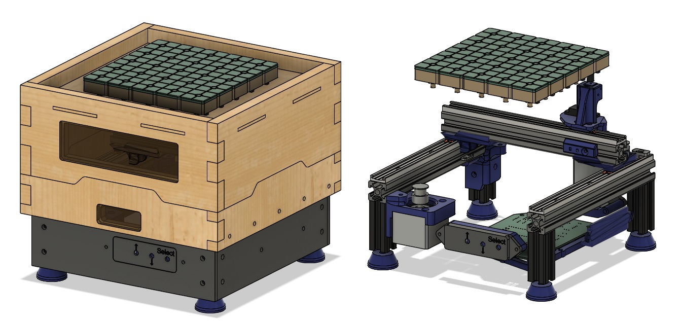
The Final Project
Summary Slide
Final Video
Parts List | BOM
X-Assembly
| Category | Item | Link |
|---|---|---|
| Mechanical | 198mm 2020-Profile (1x) | source |
| Mechanical | 198mm Igus Drylin N 17 - Low-Profile Linear Guide(1x) | source |
| Mechanical | 20mm gliding element (1x) | source |
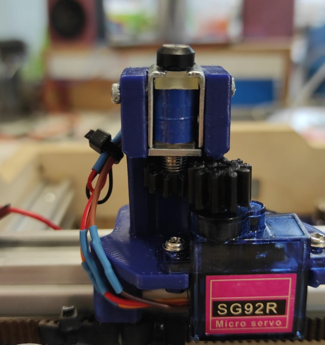
| Electronics | SG92R Servo | source |
| Electronics | 12V Solenoid | source |
| Hardware | 5x M3x10mm countersunk screw(7mm thread length) | source |
| Hardware | 3x M3 5mm T-slot nut, | source |
| Hardware | 4x M2x6mm screw | source |
| Hardware | 2x 2x1mm round neodymium magnet | source |
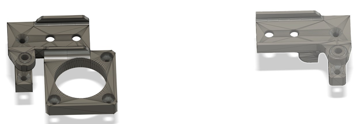
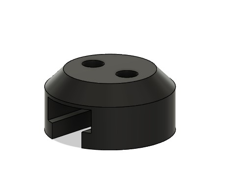
| 3D Printed | Servogear, SolenoidGear, SolenoidCap, X-Gantry, Servoblock (2x) | source |
Y-Assembly
| Category | Item | Link |
|---|---|---|
| Mechanical | 198mm 2020-Profile (2x) | source |
| Mechanical | 198mm Igus Drylin N 17 - Low-Profile Linear Guide(2x) | source |
| Mechanical | 40mm gliding element (2x) | source |
| Electronics | Stepper Nema17 | source |
| Hardware | GT2 pulley (16 teeth, 5mm bore) | source |
| Hardware | GT2 Belt | source |
| Hardware | 4x F624ZZ bearing | source |
| Hardware | 2x Melting insert M3x5.7 | source |
| Hardware | 2x M3x16mm socket head screw | source |
| Hardware | 14x M3x8mm countersunk screw (6mm thread length) | source |
| Hardware | 6x M3 5mm T-slot nut | source |
| Hardware | 4x M5x10mm countersunk screw(7mm thread length) | source |
| 3D Printed | EXCHolder1, EXCHolder2 | source |
Lower Compartment
| Category | Item | Link |
|---|---|---|
| Electronics | Stepper Nema17 | source |
| Hardware | GT2 pulley (16 teeth, 5mm bore) | source |
| Hardware | GT2 Belt | source |
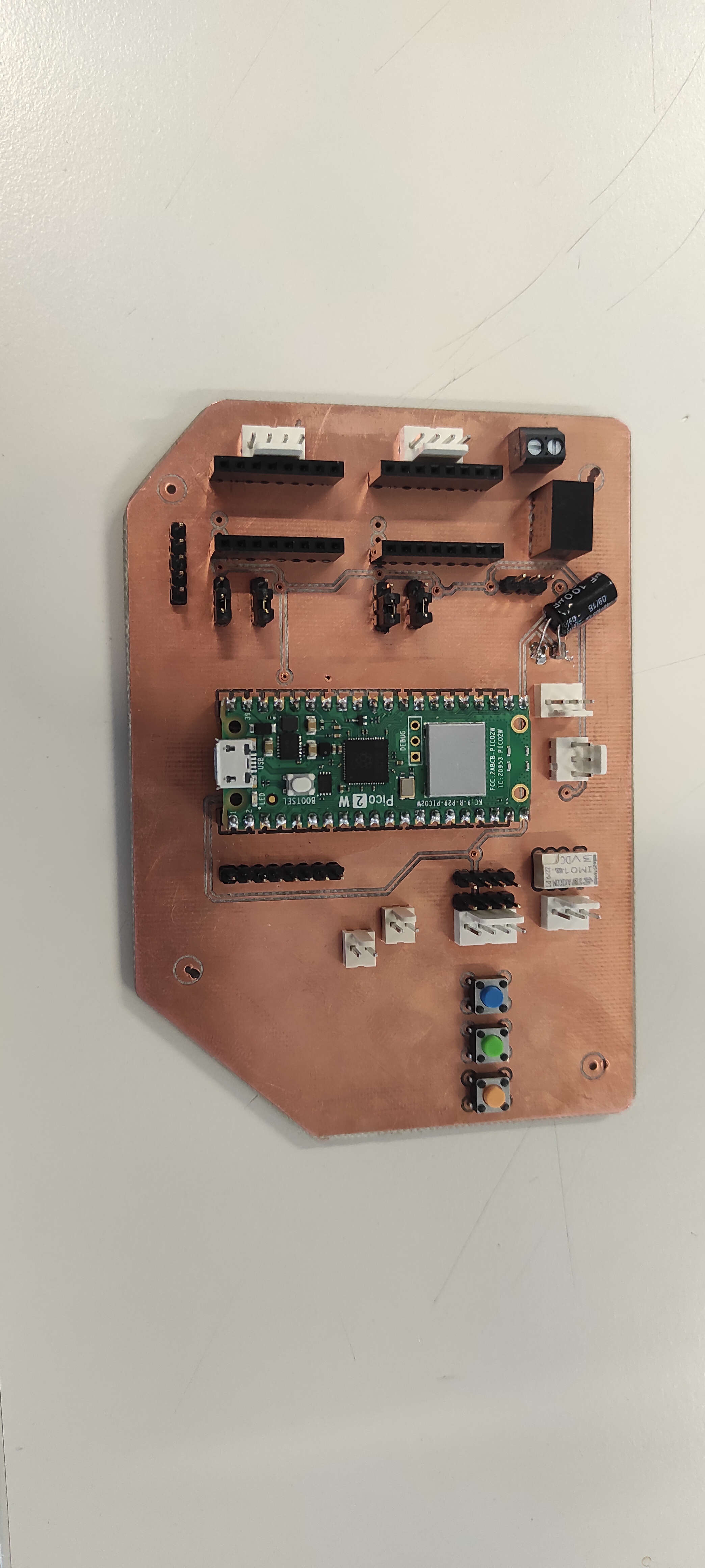
| Electronics | PD-Board | source |
| Electronics | MainBoard | source in Week 8 |
| Hardware | 4x 50mm 2020-Profile | source |
| Connectors | 2x Wago 221-415 | source |
| Hardware | 10x Melting insert M3x5.7 | source |
| Hardware | 4x M3x10mm socket head screw | source |
| Hardware | 4x 2,9mmx6,5mm Flat head Metalscrew | source |
| Hardware | 3x M3x8mm countersunk screw(6mm thread length) | source |
| Hardware | 6x M3x16mm socket head screw | source |
| Hardware | 4x F624ZZ bearing | source |
| Hardware | 26x M5 5mm T-slot nut | source |
| Hardware | 25x M5x8mm socket head screw | source |
| Hardware | 1x M5x10mm countersunk screw(7mm thread length) | source |
| 3D Printed | PDHolderA/B, ButtonHolderA/B, PCBHolder, WagoHolder , L2Assembly, L4Assembly, CableHolderA/B | source |
| Laser Cut | BotCover, RightPanel, LeftPanel, FrontPanel, BackPanel | source |
Upper Frame
| Category | Item | Link |
|---|---|---|
| Milled Parts | RLOW, RUP, LLOW, LUP, FLOW, FUP, BLOW, BUP | source Week 7 |
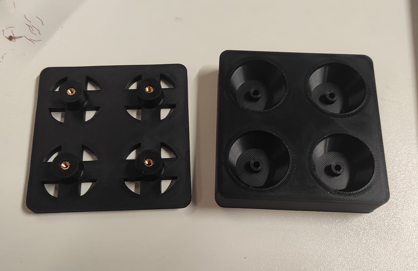
| 3D Printed | Tile_Tile (25x), Tile_Housing (25x),Tile_Topper(25x) | source |
| Laser Cut | DisplayWindow, Tileplate, WindowF (2x) | source |
| Hardware | 10x M4x16mm socket head screw | source |
| Hardware | 10x M4 5mm T-slot nut | source |
| Hardware | 50x 2x1mm round neodymium magnet | source |
| Hardware | 100x 3x1mm round neodymium magnet | source |
| Hardware | 2x Melting insert M3x5.7 | source |
| Hardware | 2x M3x16mm socket head screw | source |
Misc
The Things i list now is up to you, what exactly you want to use:
- Cables for everything
- Superglue like this
- mesh sleve like this
- Filament like this
- UV-Resin like this
Downloads
Software
Information to the UI: You need to install the ControlP5 libray by Adreas Schlegel, through the librarymanager(Sketch -> import library -> Manage Libraries) in Processing.
FP_UI with Processing Pi Pico Firmwareother Stuff
- Download "wago_221-415_2x1_holder.stl" from file section
- In the Misc.zip you'll find the Feet to print and the mold to cast them in Silicone or something similar. There are also the ZipTie Blocks i created.
- Here is also the lastest Version of the F3z-Archivefileof the Final
Important Stuff
Models I used in my and what i used it for, which are not mine
Used for reference
Used in final Project
My Road to the Prototype
What could be my final Project????(week 1)
To give you some Background Info: I love Playing Dungeons and Dragons and switched to mostly be the Gamemaster. For that i have something in Mind. I want to make a MechanicalDungeon, the MechaDungeon. The Plan ist to have 1 inch tiles, which acts like Walls or Floor. This Tiles will then be rised or lowered by some sort of mechanics.
First Idea
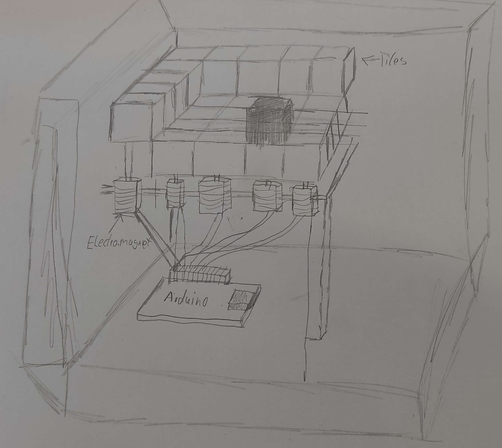
The first idea was to use some sort of Actuators like a electromagnet or a servo. At some Point i realized, that this would be a enormous ammount of actuators. I planned a Board size of 10x10 tiles which would be 100 actuators.
second Idea
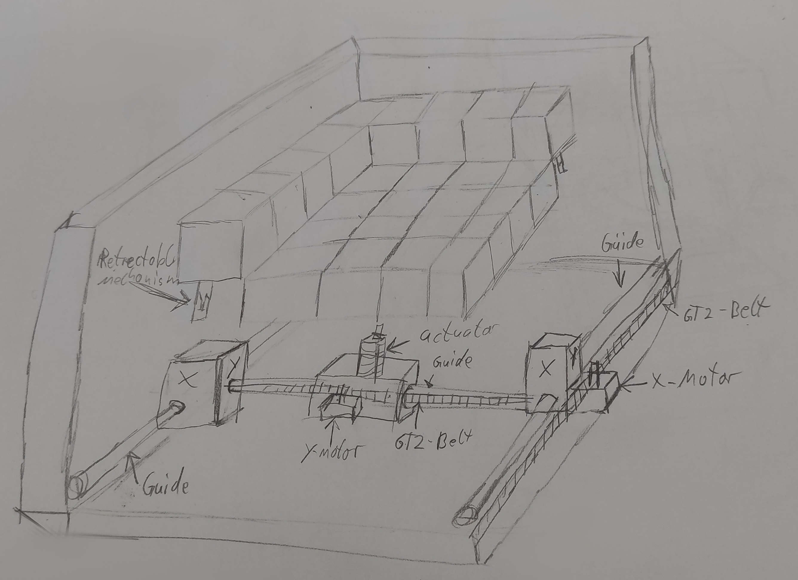
After Hours of thinking and fidgiting around with my Pen, something came into my mind. Why dont use a similar Mechanism like the Retractable Pens. I would combine this with an XY Bot and an Actuator and would a cheap to extend Version, which is also simple to realize.
Research
- 'Wie funktioniert eigentlich ein Kugelschreiber?'. Der Lehrerfreund.
- 'The Ballpoint Mechanism: How Does a Ballpoint Pen Work?'. Goldspot Pens.
Week 2
In Week 2 I overhauled the tile mechanism, I switched from a latching to a Twisting mechanism.
Week 4
In Week 4 I started with the Code for my MechaDungeon. I implemented the Menu, getting Dungeons from Serial and Controlling the Machine with Buttons
Week 5
In Week 5, I made some tweeks in the Twisting Mechanism and the top of the Tile
Week 6
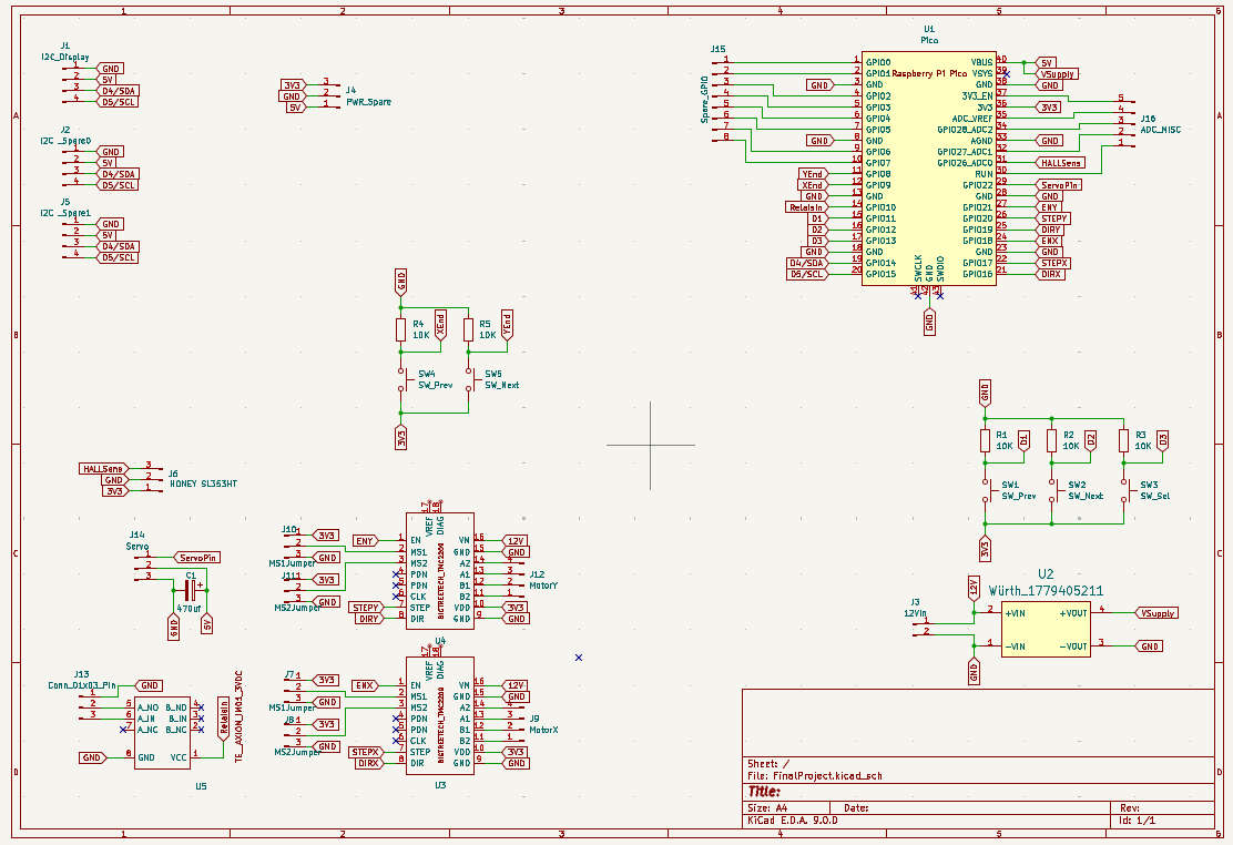
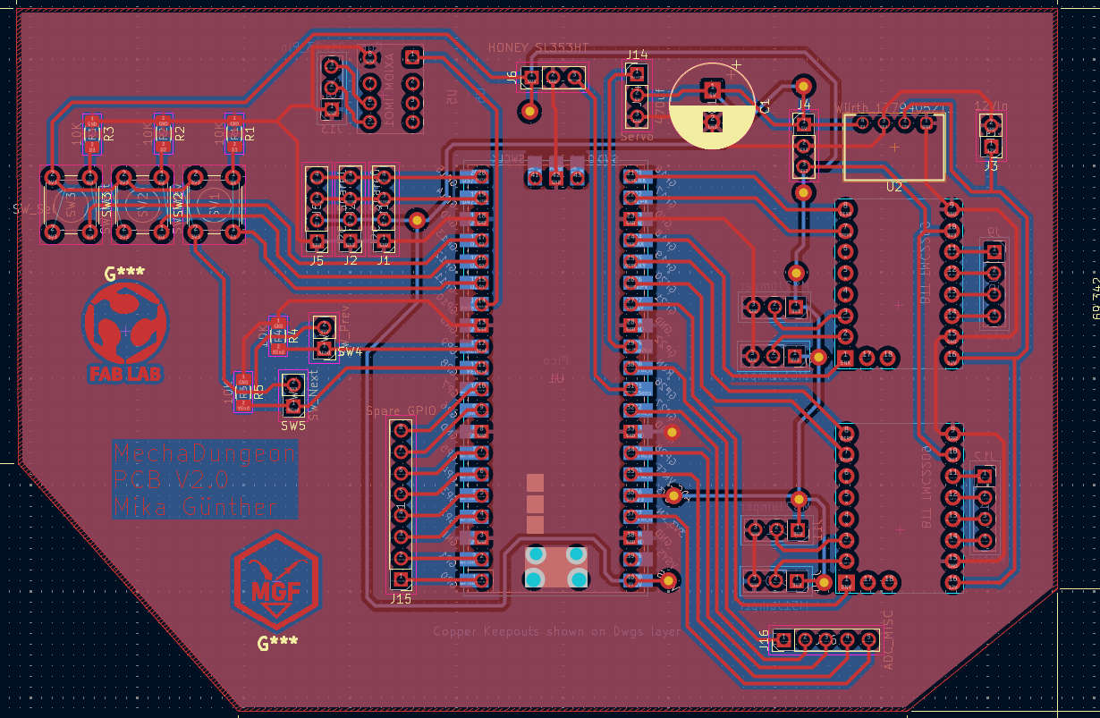
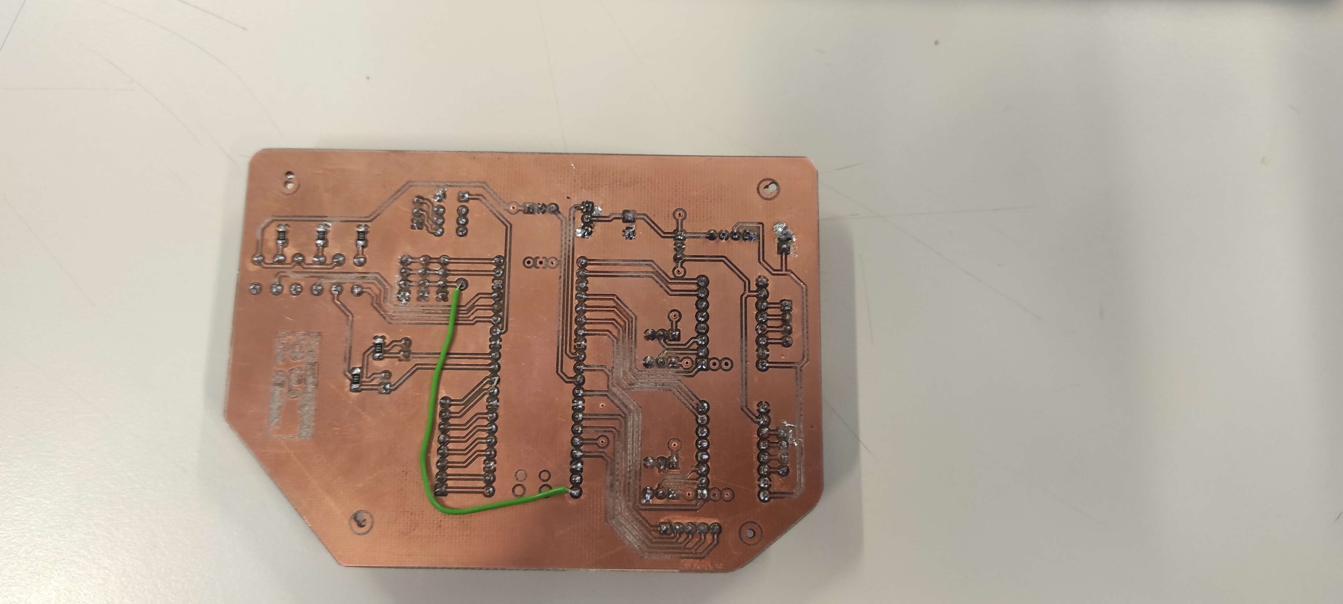
In Week 6 I designed the PCB for the MechaDungeon
Week 7
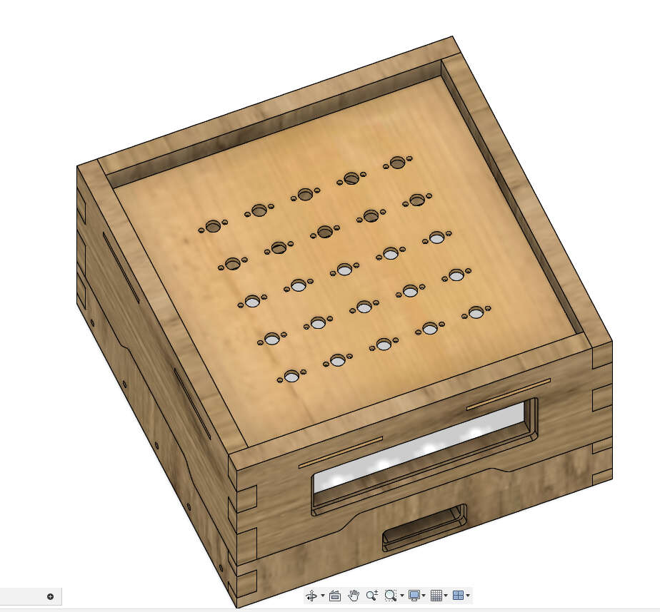
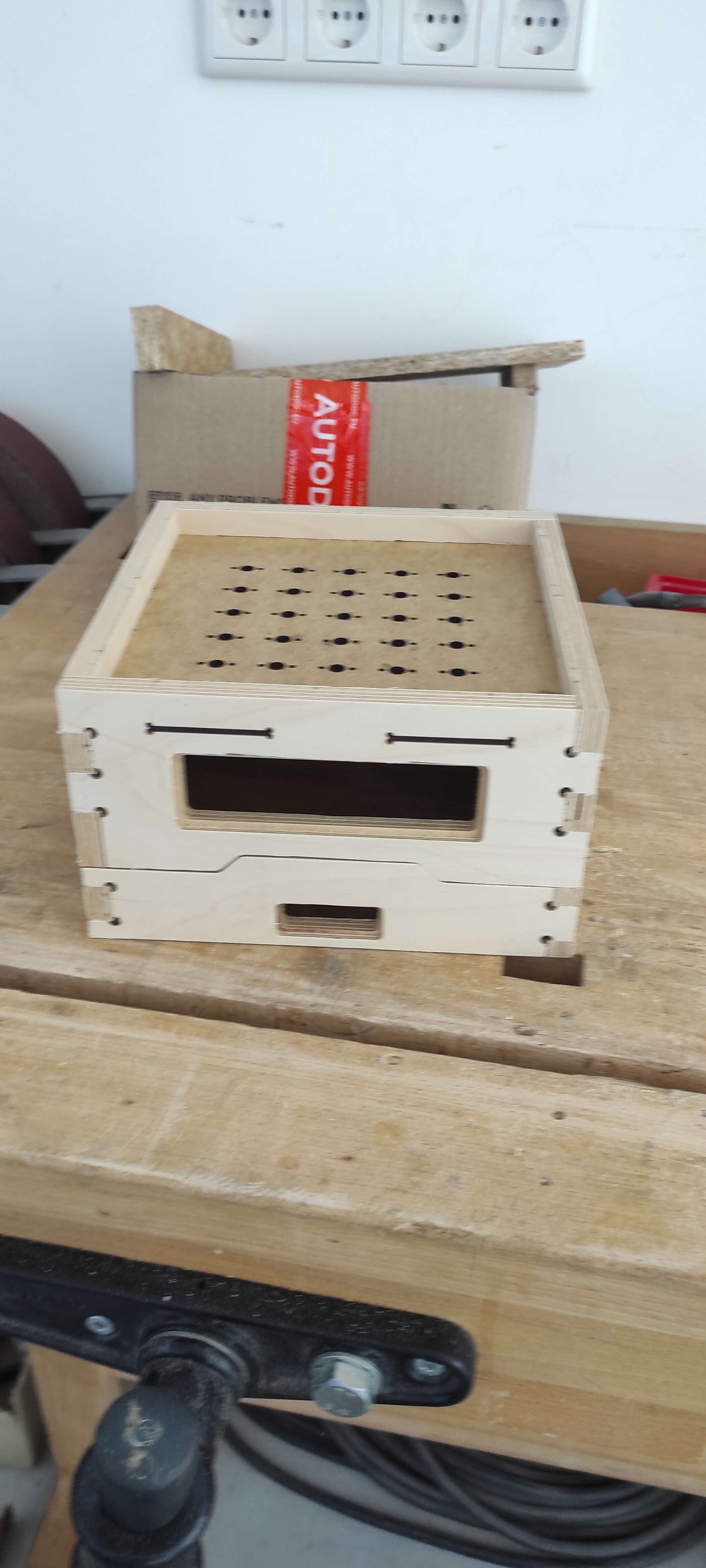
In week 7. Computer controlled machining you saw, that i milled the main frame for my final Project. I also Lasercut the Tileholder
Week 8
In Week 8, I produced the Board made in Week 6
Week 11
In Week 11, Tried a bit with MQTT and Im thinking using it to get DATA "OTA"(Over the Air)
Week 12 + 13
In Week 12+13, We tried a bit with Stepper and Drivers, what was beneficial for me. I also figured out, that leen couldn't communicate with my board to the Drivers
Midterm
What is done
- Tile Mechanism
- Main Frame plus Tileholder
- Electronics V1
What needs to be done
- extensive Electronics Testing
- Internal Rail System
- Power Supply
- lifting+twisting Mechanism
- Human-Machine Interface
- internal wiring
| When | What |
|---|---|
| Week - 14 | extensive Electronics Testing|Internal Rail System |
| Week - 15 | Human-Machine Interface|lifting+twisting Mechanism |
| Week - 16 | Internal Wiring|Power Supply |
| Week - 17 | Bug Fixes |
| Week - 18 | Bug Fixes |
| Week - 19 | Bug Fixes |
Week 15
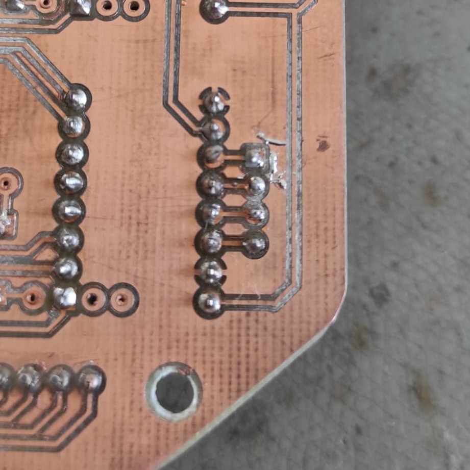
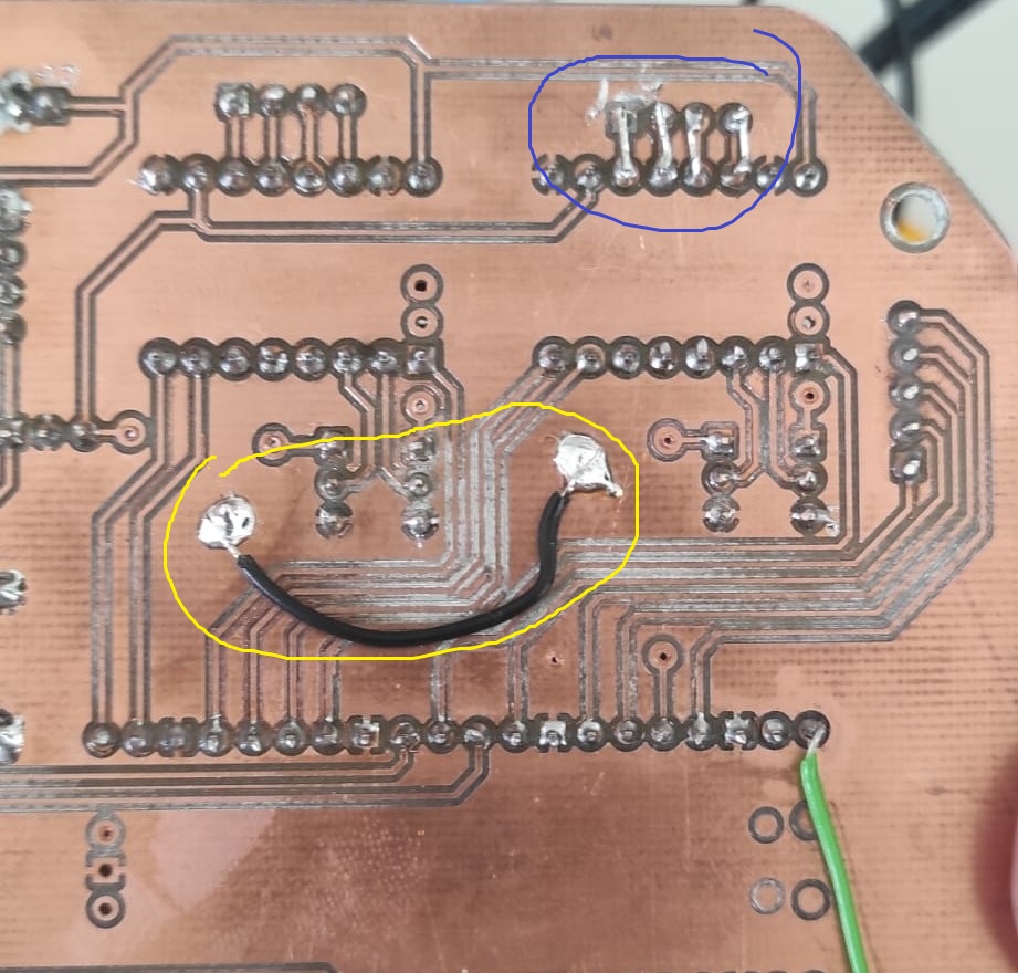
In Week 15 I figured out, what the problem was with my Board. I had some bad solderjoints and ripped pads.
Week 16
In Week 16, I put more Time in the Last Design Steps for the Final Project
Week 17
In Week 17, I designed the Tile Toppers, Did most of the left assembly and made some decisions
Problem: Y-Assembly
The 20mm gliding elements used in the Y-Assembly were to short, what lead to slag in the movement and so breaking, because of build up tension, i exchanged the gliding elements to 40mm ones.
Cut of Features!
Because of Time reasons i decided to remove the Feature of the Standalone function. That means i wont use the buttons and also the display. Instead I go full Interfacing with Processing over Serial.
Feets
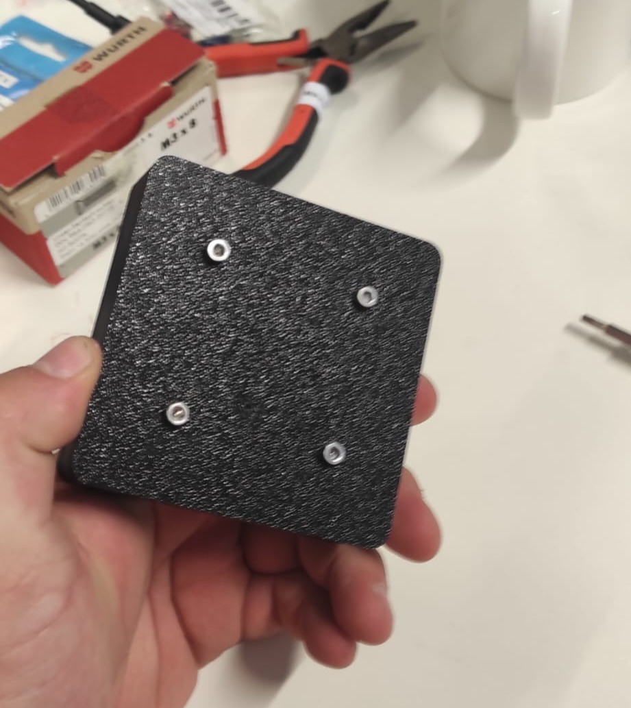
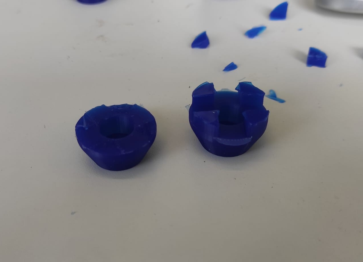
There are 2 possibillities for the Feets. The first is to nuy them, the second is to cast them. I went on and casted them. For that purpose i made a mold for 4 feets, which are designed for m6 Bolts. It is a two part which is screwed together.
After filling the mold with silicone, i took out the cast, and trimmed the flashing and sprues. Yes there where a bit massive, but i wanted as much ventelation as possible
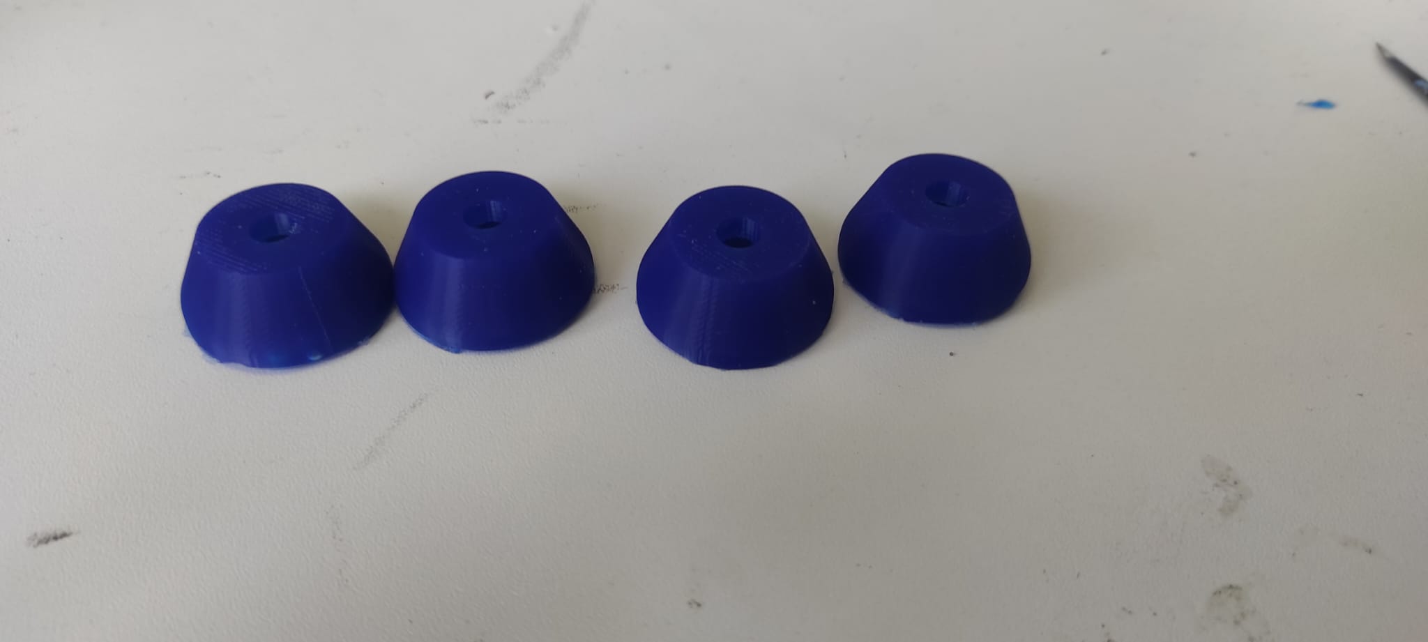
At the Top I provide the STLs for the Mold, aswell as from the feet, if you want to print them in TPU or so.
Week 18
Besides all the "Paperwork" you find in this weeks assignment I worked on, the tiles, the Cablemanagement and the first Steps of my "baby". In addition, I programmed the UI in Processing.
Tiling
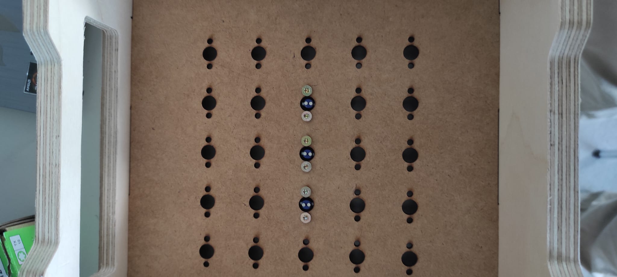
The Tiling Process, was easy. After all prints where done, i started by gluing the magnets into the "TilePins" this is done in a way, that the polarity is matching with the magnets in the turning mechanism.
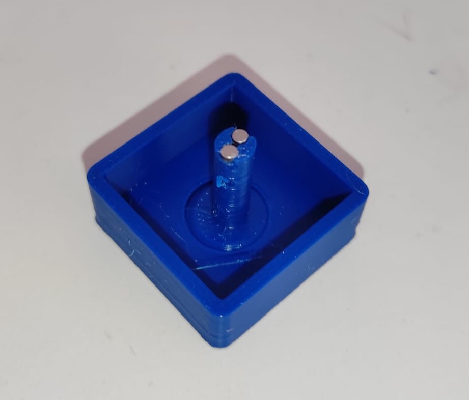
Second Step was put the "Housing"(Black) over the "TilePins" and inserting the "Guidpin", which is a 1,75mm piece of filament. In my case, i used white ASA laying in the recycling bin
Last step, was screwing the Tile-assembly onto the "TilePlate" with 3mmx10mm woodscrews.
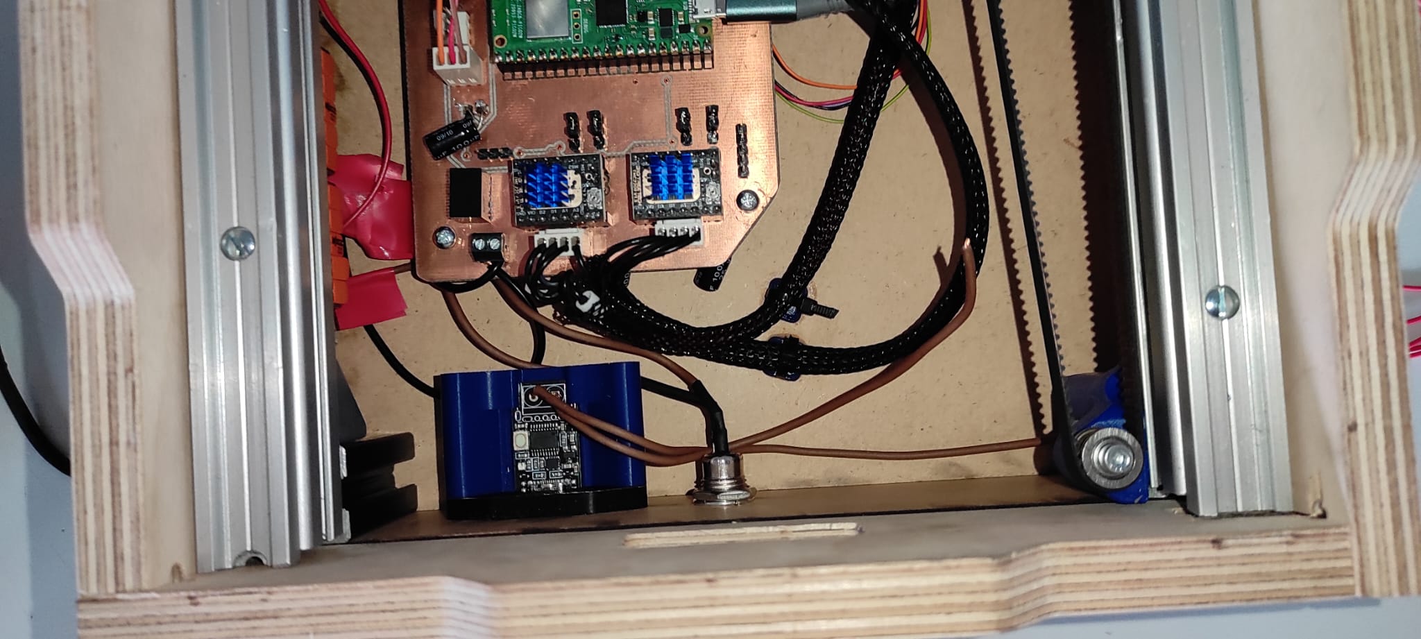
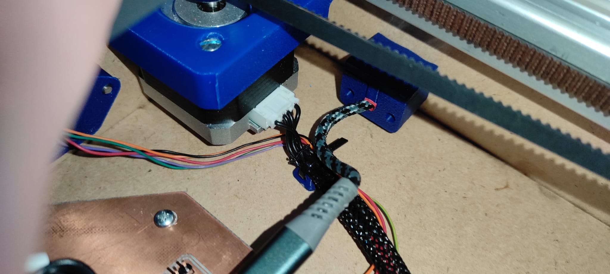
Cablemanagement
For Cablemanagement i created ZipTie-Blocks, you can Download at the Top
First Movements
In the video, you see the first steps. Its just the Homing function but ist a start.
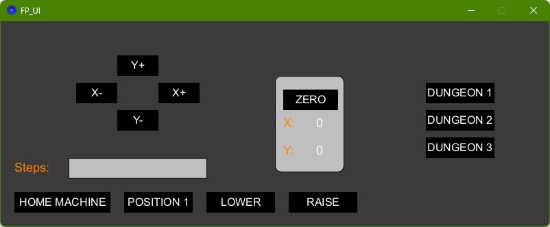
UI
I created the UI using Processing, based on the code from Week 15 . You find the .pde at the top.
Overview
This Processing sketch creates a graphical user interface to control the MechaDungeon using buttons and serial communication.
Libraries and Variables
It uses the ControlP5 library for the GUI and processing.serial to communicate with
Arduino. It tracks xPos and yPos as the current positions and reads step values from a
text field.
setup()
Initializes the window size, loads the font, connects to the serial port, and sets up GUI elements:
- Arrow buttons for X and Y movement
- Predefined dungeon buttons
- Home, raise, lower, and position controls
- A text input field for step size
draw()
Updates the background and draws a small panel that shows current X and Y steps. It also labels the input field and status values.
getSteps()
Reads the number entered in the text field. Converts it to an integer for use in movement commands.
Movement Functions
XPlus()/XMinus(): Move X-axis forward/backwardYPlus()/YMinus(): Move Y-axis up/downresetSteps(): Resets step counters to zero
Tile and Dungeon Commands
raise(): Sends a raise tile commanddown(): Sends a lower tile commandDungeon1(),Dungeon2(),Dungeon3(): Build different predefined dungeon layoutspos1(): Moves to a defined starting position
home()
Sends a homing command to reset the machine to its origin using the endstops.
Pi Pico Firmware
Based on the code of our Machine assignment in Week 12 and 13 and the code from Week 15, I created the Firmware for the Pi Pico. The functions, i implemented are:
Overview
This Arduino sketch controls a 2-axis system using stepper motors, a servo, and a solenoid. It moves to different positions, raises or lowers tiles, and can build a predefined layout like a dungeon map.
Global Setup
The code sets up pin numbers for motors, endstops, and the solenoid. It also defines speeds and step counts, and initializes a servo on pin 22.
setup()
Sets the pin modes, disables motors, attaches the servo, and sets its start position. The solenoid control pin is also initialized.
loop()
Runs once to home the machine. Then listens to Serial input for movement commands (e.g., x+100) or
word commands like raise, lower, or d1.
stepX(steps, dir) and stepY(steps, dir)
These functions move the stepper motors a given number of steps in the specified direction (HIGH or LOW), with a short delay between each step.
home()
Moves the X and Y axes toward their endstops until triggered. This sets the machine's start position.
pos1()
Moves to a predefined position after homing. Useful for testing or setting a starting tile.
dungeon1()
Moves through a sequence of positions and calls raise() at each tile to build a specific layout. This
is a full automation sequence.
raise()
Moves the servo to 180°, activates the solenoid, then slowly rotates back to 0°. It also performs small "nudges" in case of mechanical sticking.
lower()
The opposite of raise(). Starts at 0°, activates the solenoid, slowly rotates to 180°, and resets.
isAxisCommand(cmd)
Checks if a received serial string is a valid axis move command (e.g., x+200 or y-150).
extending the tile
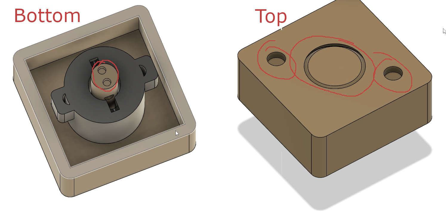
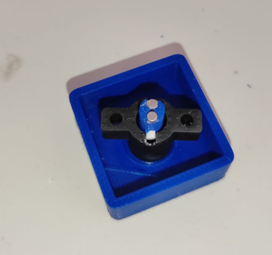
After the first Tests with the rising and lowering mechanism, I had a problem. After rising the Tile, the Solonoid stayed in the risen position, because the magnets where too strong. I first tried to solve the problem by just moving away, but the lifting head sticked into the TilePlate, what lead to a blockage. The solution was to making the TilePin longer and the SolonoidCap shorter. The change was 4mm. I also chamfered the SolonoidCap, what gave me some safety.
W19
this week, i created the Summary Slide and Video. You find both at the top. You also find in This Weeks Assignment the Dessimination Plan and Future work.