Week 16 - System Integration
This Week i tried to designed all the rest, i needed to manufacture or edit, to get coding started, for my final Project
The Electronics
Overview
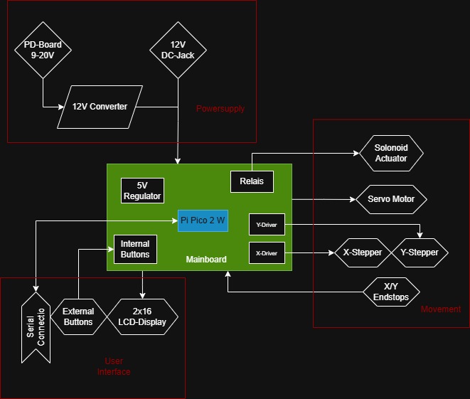
The system integration diagram illustrates the architecture of my final project, which is based on a Raspberry Pi Pico 2 W acting as the central controller. The overall setup is organized into four main areas: power supply, mainboard, user interface, and movement and actuation.
The power supply section includes a 12V input provided either through a standard DC jack or as alternative, a PD-board, wihich is supposed to accept between 9V and 20V, with a 12V converter to get the required 12V.
At the core of the system is the mainboard, featuring the Raspberry Pi Pico W. This board is responsible for coordinating the entire system. It is connected to internal buttons for direct input, a relay for switching the solenoid actuator, and stepper motor drivers for controlling movement along the X and Y axes. A 5V regulator is used to step down the voltage for components that require lower power, including the microcontroller and interface elements.
The user interface allows interaction with the system through external buttons and a 2x16 character LCD that displays status information. A serial connection through USB will also be implemented, for creating new dungeons.
For movement and actuation, the system uses stepper motors on the X and Y axes, each with corresponding drivers and endstops to define travel limits. Additional actuators include a servo motor and a solenoid, which peform thhe action of lifting and locking the tiles in place.
Power and Current Consumption
| Component | Voltage | Max Current | Power (W) |
|---|---|---|---|
| Nema17 Stepper Motor (2x) | 12V | 2 × 1.2A = 2.4A | 2 × 12V × 1.2A = 28.8W |
| SG90 Servo | 5V | 0.65A | 5V × 0.65A = 3.25W |
| 12V Solenoid | 12V | 0.6A | 12V × 0.6A = 7.2W |
| LCD 16x2 Display | 5V | 0.06A | 5V × 0.06A = 0.3W |
| Raspberry Pi Pico W | 5V | 0.3A | 5V × 0.3A = 1.5W |
| Total | ~41.05W | ||
| Current at 12V | ~3.42A | ||
The "Sub-Assemblys"
X-Assembly
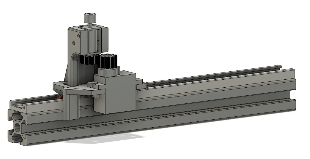
The X-Assembly contains the X-Sled and the Lifting and Locking/Twisting Mechanism. I also needed to create the reference model for the Solonoid, because i couldn't find one in any database, fitting my solonoid. I created the model in the extended position. The Sled is placed on a 20mm gliding element inside an 198mm Igus Drylin N 17 - Low-Profile Linear Guide, which is screwed on a 198mm piece of 2020 aluminum T-Slot extrusion(bosch profil)
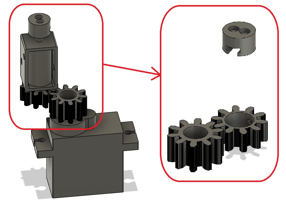
Lifting/Locking part
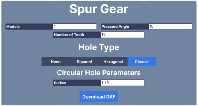
The Twisting Mechanism was done, by adding two gears with a module of 1, a pressure angle of 15° and a teethcount 10. The DXF, i created with a Spurgear DXF creator had also a circle with an radius of 1.15mm in the middle.
Carrier
The Carrier is pretty simple. On the underside, it has two holes, to accept the linear guid. the top part has the mounting for the solonoid. The lower part, has a adjustable mounting for the servo, to adjust the actual pressure on the Gears. To attach the GT2 Belt to the Assembly, i made 2x m3 threads at the bottom, to accept 2x m3 screws, so i can make loops at the end of the Belt, and use the screws as Hooks.
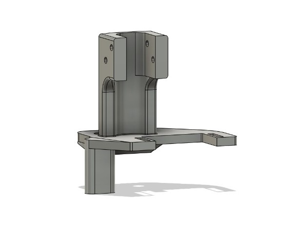
X-Assembly Result
The Gears are Printed with ABS-Like 3.0 resin from elegoo on the elegoo saturn 4 ultra. The SolonoidCap and the Tile_Housing's will be printed in this material too. The Actual Carrier is printed like all other 3D-printed parts on the BambuLab A1 with Verbatim PLA. On the Bottom of the Carrier, you can see, the the belt is looped at the and and held in this shape by zipties. The loops are held in place by two m3 screws.
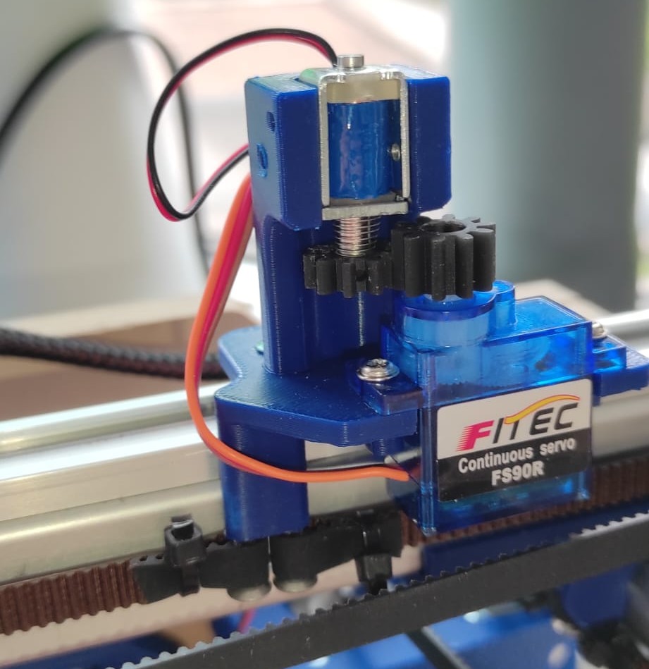
On the Image is the wrong servo. I used a continous servo in the Image. For the final Prototype, I need a 180° servo.
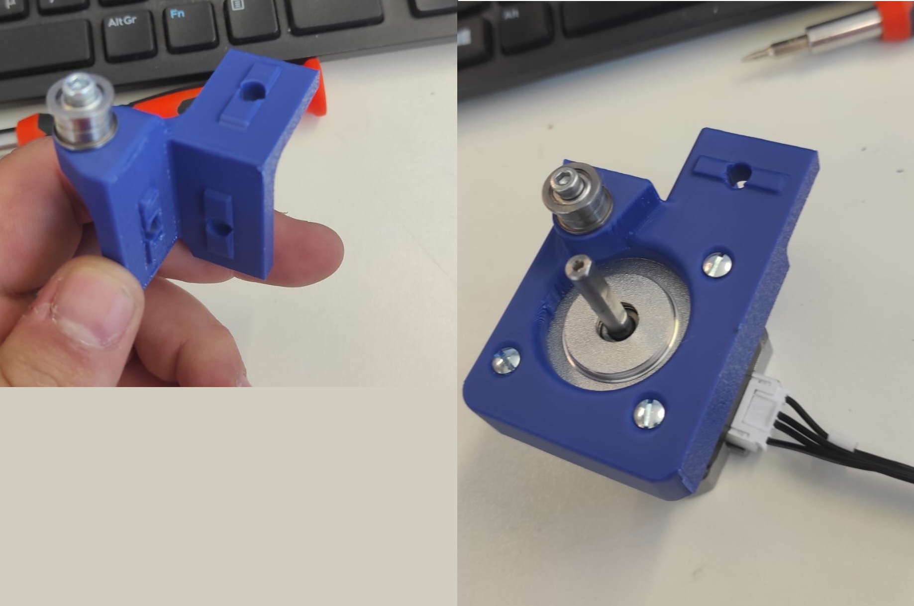
Y-Assembly
The Y-Assembly consists of a Stepper motor with a GT2-Pulley, 2 Rollers and, And the "EXC-Holder". EXC, because i called the 2020-Profile of the X-Assembly "ExtrusionC(EXC)" Both EXC-Holder are attached to individual 20mm gliding elements inside 198mm Igus Drylin N 17 - Low-Profile Linear Guide, which are screwed on 198mm piece of 2020 aluminum T-Slot extrusions(bosch profiles)
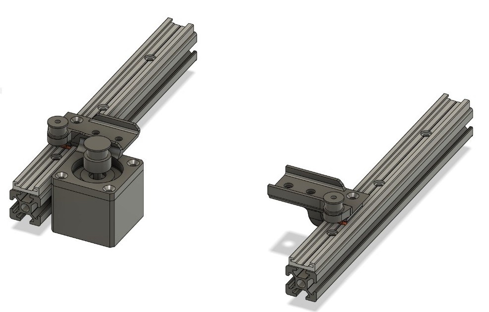
"EXC-Holder"
Both "EXC_Holder" have a spot for a m3 heat insert, to secure the roller for the GT2 Belt. HolderA also has a mounting for a Nema17 Stepper Motor with an GT2-Pulley.
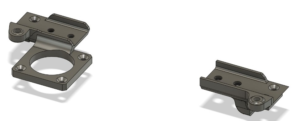
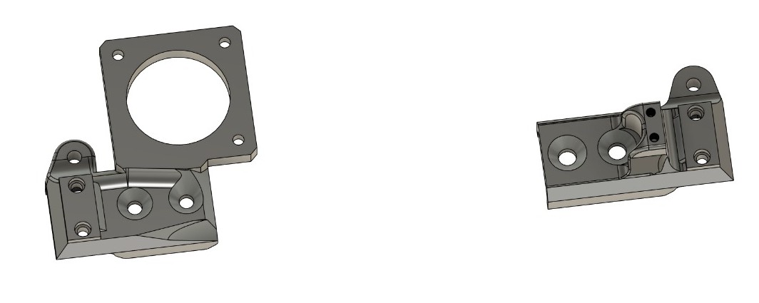
Now in 3D-printed and with Rollers and Motor
Y-Assembly Result
Both Holders are connected to the Extrusion of the X-Assembly and to the gliding elements of the Linear Guides
The Image you see for the Y-Assembly Result is the already updated Variant from Week 17.
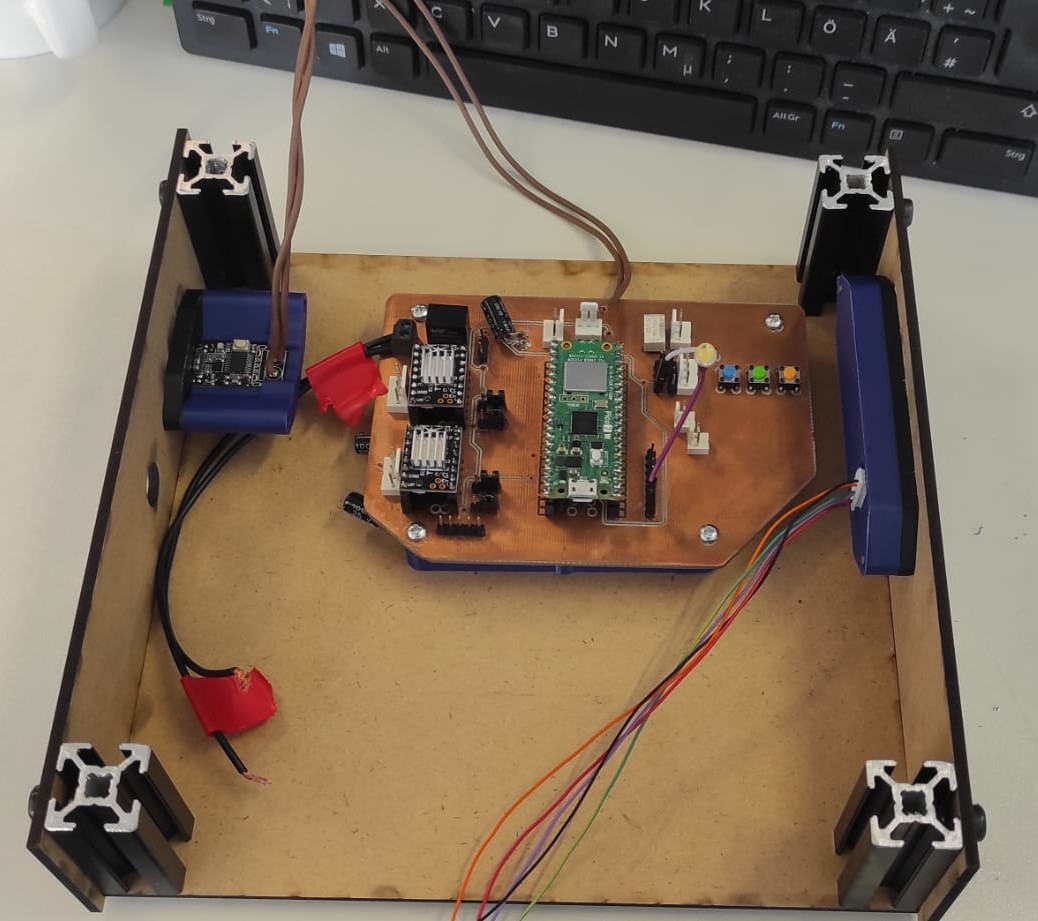
Lower Compartment
The lower compartment houses all the Electronics. At this Point, i made the PCBHolder, the Button Holder and the PowerDelivery Board Holder.
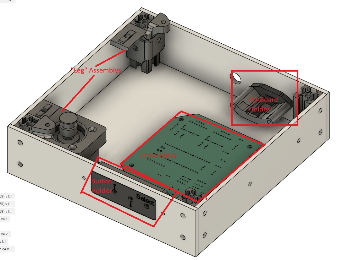
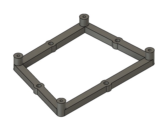
PCB Holder
For the PCB Holder i just made a frame on which i screwed the PCB with four 2,9mmx6,5mm Woodscrews. The Holder itself has m3 heating inserts which are used to screw the Holder with four m3x10mm screws to the Bottom cover
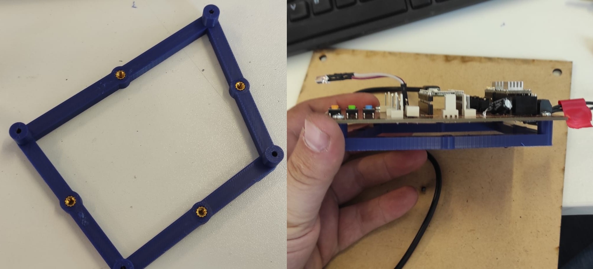
PD-Board Holder
For the PD_Board Holder, A two part holder. The first part accepts the usbc part and creates an indentation, that the usb-c cable also fits without exposing the inside. The back part accepts two m3 Heatinserts, so that the assembly can be screwed to the Cover plate. The cover plate also has a hole for a Barrel-Jack.
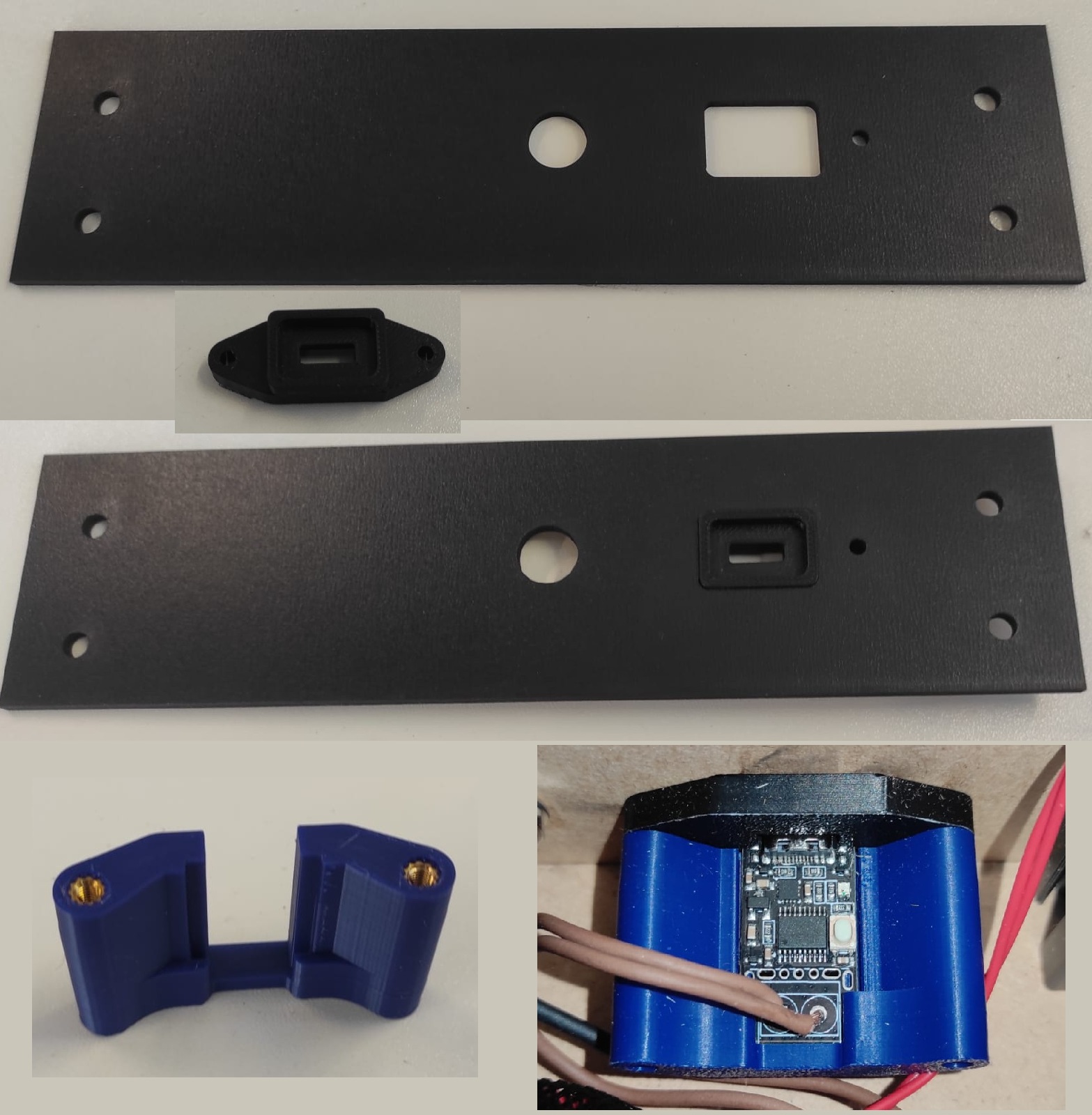
Button Holder
The Buttonholder works similar to the PD-Board Holder the front part function as cover and as spacer. The back has a coutout for the Connector and ans Heatinserts again, to mount both parts to the cover plate.
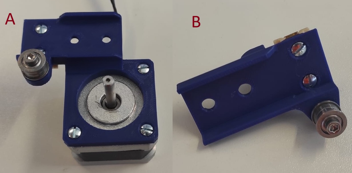
"Leg" Assemblies
The Leg assemblies/Motor and Roller Holder are similar to Y-Assembly. The difference is, that they are stationary. they also purpose as one connection point between the 2020 profiles.
Here is an image mounted already with the Belts.
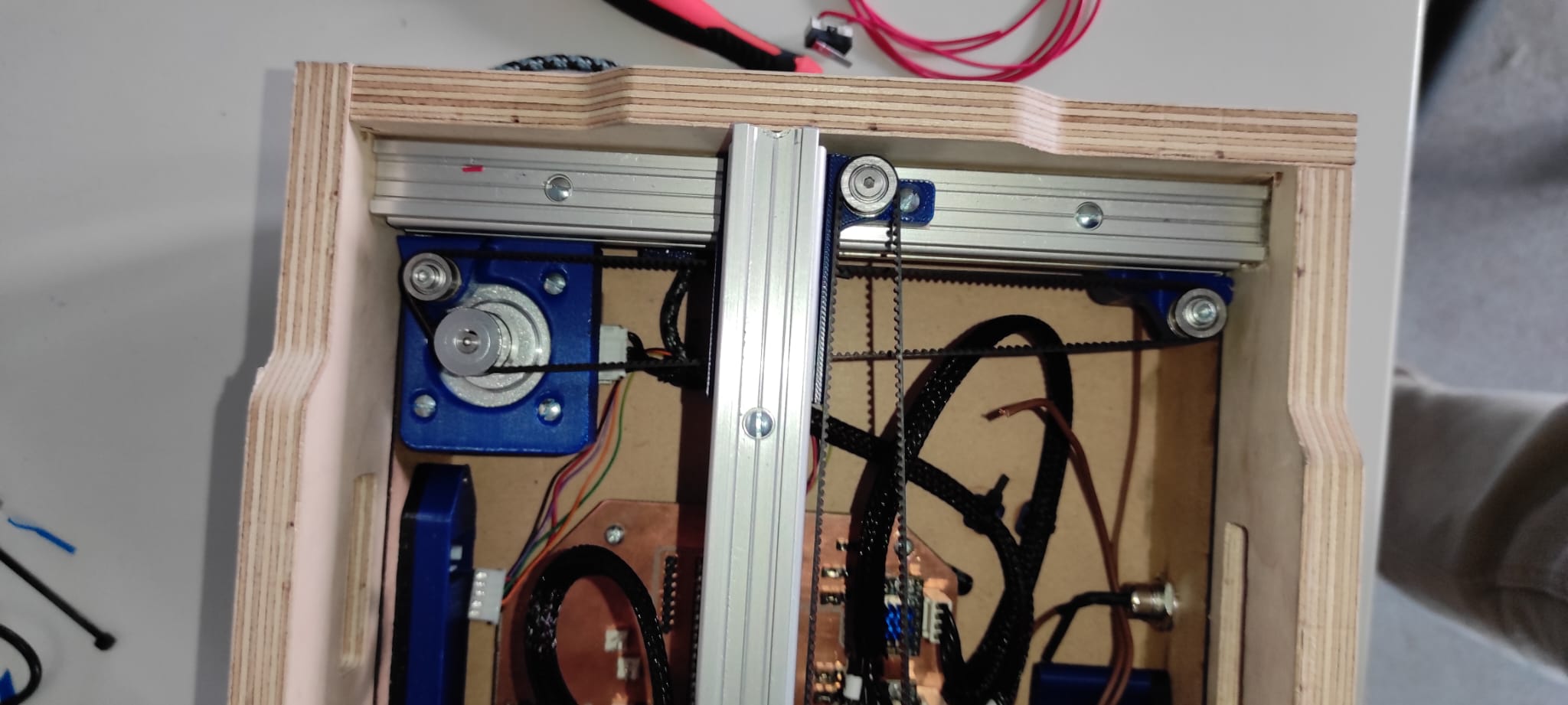
Lower Compartment Result
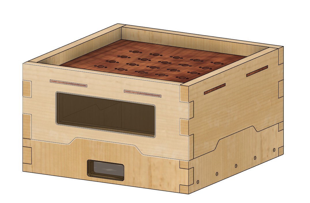
Upper Frame
Here is not much to say other than, that this is documented in Week 7 - Computer controlled machining.
Results
Downloads
All the Downloads you'll find on the Final Project Page!