Week 15 - Interface and application programming
In this week I played a bit with Processing to create an Interface which communicates with the Board i Produced in Week 8.
In our group assignment, i was responsible for the Workflow of Processing and HomeAssistant
Help from ChatGPT
I never worked with Processing, so i asked ChatGPT 3 things. How to create "an interface with processing with 4 arrow buttons and one text input field with an send button",How to work with Serial and how would i establish a connection with an Arduino and the Interface.
Heres the ConversationThe Interface
ChatGPT gave me a programm with a library ControlP5. ControlP5 is a GUI (Graphical User Interface) library for Processing that helps you easily create user interface elements like: Buttons, Sliders, Text fields, Checkboxes, Dropdown lists, etc.It was just an Examplecode, with no logic in the Callbackfunctions of the Buttons. One Problem occured. As I copy/pasted the code and started it, there was no response with the GUI. So I started investigating and found the Problem. ChatGPT forgot to add the draw() function. which lead to the fact that the cp5.draw(); was executet but the by the library drawn Elements weren't responsive. they were just there and not interactable. by just adding
void draw(){

}
to the code, every thing worked. In Processing, the draw() function is crucial for the sketch's continuous
update loop. Even if you're not drawing anything manually, Processing still relies on draw() to keep
everything responsive, including GUI libraries like ControlP5.
//Code directly from ChatGPT without draw() function
import controlP5.*;

ControlP5 cp5; //create object "group"
String inputText = "";

void setup() {
  size(400, 300);
  cp5 = new ControlP5(this);

  // Arrow buttons
  cp5.addButton("Up")
     .setPosition(170, 50)
     .setSize(60, 30);

  cp5.addButton("Left")
     .setPosition(110, 90)
     .setSize(60, 30);

  cp5.addButton("Right")
     .setPosition(230, 90)
     .setSize(60, 30);

  cp5.addButton("Down")
     .setPosition(170, 130)
     .setSize(60, 30);

  // Text input
  cp5.addTextfield("input")
     .setPosition(100, 200)
     .setSize(200, 30)
     .setAutoClear(false);

  // Send button
  cp5.addButton("Send")
     .setPosition(310, 200)
     .setSize(60, 30);
}

void Up() {
  println("Up button pressed");
}

void Down() {
  println("Down button pressed");
}

void Left() {
  println("Left button pressed");
}

void Right() {
  println("Right button pressed");
}

void Send() {
  inputText = cp5.get(Textfield.class, "input").getText();
  println("Send button pressed with text: " + inputText);
}
Serial Communication
After asking, how i would create a serial connection with Processing as "Parent" and the Microcontroller as
"Child" it changes the code of Processing by adding the Serial Setup and the serial.write functions in the
callbacks of the Buttons.
On the Microcontroller(MC) side, its just an example of reading Strings on the serial port. In the loop function,
the MC is listening to the serial Port the Whole time and if something was send, it reads it. In comparison: In
the 4th Week I used a different methode, where i read the last send String in the
Buffer on a button press.
Processing
//Processing Code, provided by ChatGPT
import controlP5.*;
import processing.serial.*;

ControlP5 cp5; //create object "group"
Serial myPort; //create serial connection
String inputText = "";

void setup() {
  size(400, 300);
  cp5 = new ControlP5(this);

  // Setup GUI
  cp5.addButton("Up").setPosition(170, 50).setSize(60, 30);
  cp5.addButton("Left").setPosition(110, 90).setSize(60, 30);
  cp5.addButton("Right").setPosition(230, 90).setSize(60, 30);
  cp5.addButton("Down").setPosition(170, 130).setSize(60, 30);
  cp5.addTextfield("input").setPosition(100, 200).setSize(200, 30).setAutoClear(false);
  cp5.addButton("Send").setPosition(310, 200).setSize(60, 30);

  // Setup Serial
  printArray(Serial.list());  // View available ports
  String portName = Serial.list()[0];  // Adjust index if needed
  myPort = new Serial(this, portName, 9600);  // Match baud rate with Arduino
}

void draw() {
  background(240);
  fill(0);
  textSize(14);
  text("Current input: " + inputText, 100, 250);
}

// Button callbacks
void Up()    { myPort.write("UP\n"); println("Up"); }
void Down()  { myPort.write("DOWN\n"); println("Down"); }
void Left()  { myPort.write("LEFT\n"); println("Left"); }
void Right() { myPort.write("RIGHT\n"); println("Right"); }
void Send()  {
  inputText = cp5.get(Textfield.class, "input").getText();
  myPort.write("MSG:" + inputText + "\n");
  println("Sent message: " + inputText);
}
Arduino
//Arduino Code, provided by ChatGPT
void setup() {
  Serial.begin(9600);
  pinMode(LED_BUILTIN, OUTPUT);  // For demo purposes
}

void loop() {
  if (Serial.available()) {
    String command = Serial.readStringUntil('\n');
    command.trim();  // Remove whitespace/newlines

    if (command == "UP") {
      Serial.println("Moving up");
      digitalWrite(LED_BUILTIN, HIGH);  // Example action
    }
    else if (command == "DOWN") {
      Serial.println("Moving down");
      digitalWrite(LED_BUILTIN, LOW);
    }
    else if (command.startsWith("MSG:")) {
      String msg = command.substring(4);
      Serial.print("Received message: ");
      Serial.println(msg);
    }
  }
}
Microcontroller
board setup
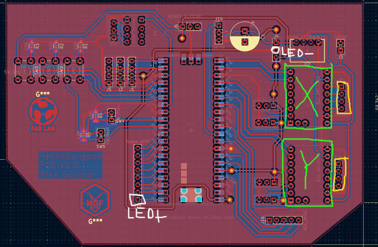
For driving the Nema17 Stepper, i used 2x SilentStepStick TMC2100 from Stephan Watterott. These where plugged at the Driver locations on the rigth side of the Board(Green) and the actual motors rigth next to the drivers(Yellow). The LED was plugged onto GP0 with the Anode and onto GND with the cathode(both white).
Code
What i mainly did was taking the movment from 12th weeks group assignment and combined it with the serial read code. Then, I added the commands for all dircetions of the motors and the ON/Off Commands for the LED
            #define X_STEP 17  // X motor STEP pin
            #define X_DIR 16   // X motor DIR pin
            #define ENX 18     // X motor Enable pin

            #define Y_STEP 20  // Y motor STEP pin
            #define Y_DIR 19   // Y motor DIR pin
            #define ENY 21     // Y motor Enable pin


            void setup() {
              Serial.begin(115200);
              pinMode(0, OUTPUT);  // For demo purposes
              //Stepper Pins
              pinMode(X_STEP, OUTPUT);
              pinMode(X_DIR, OUTPUT);
              pinMode(ENX, OUTPUT);
              pinMode(Y_STEP, OUTPUT);
              pinMode(Y_DIR, OUTPUT);
              pinMode(ENY, OUTPUT);
              // Enable motors
              digitalWrite(ENX, HIGH);
              digitalWrite(ENY, HIGH);
            }

            void loop() {
              if (Serial.available()) {
                String command = Serial.readStringUntil('\n');
                command.trim();  // Remove whitespace/newlines

                if (command == "ON") {
                  digitalWrite(0, HIGH);  // Example action
                  Serial.println("ON");
                }
                else if (command == "OFF") {
                  digitalWrite(0, LOW);
                  Serial.println("OFF");
                }
                else if (command == "y-") {
                  digitalWrite(ENY, LOW);
                  delay(60);
                  turnY(false,10);
                  Serial.println("Y-10");
                  delay(60);
                  digitalWrite(ENY, HIGH);
                }
                else if (command == "y+") {
                  digitalWrite(ENY, LOW);
                  delay(60);
                  turnY(true,10);
                  Serial.println("Y+10");
                  delay(60);
                  digitalWrite(ENY, HIGH);
                }
                else if (command == "x-") {
                  digitalWrite(ENX, LOW);
                  delay(60);
                  turnX(false,10);
                  Serial.println("X-10");
                  delay(60);
                  digitalWrite(ENX, HIGH);
                }
                else if (command == "x+") {
                  digitalWrite(ENX, LOW);
                  delay(60);
                  turnX(true,10);
                  Serial.println("X+10");
                  delay(60);
                  digitalWrite(ENX, HIGH);
                }
              }
            }

            // Turn Y-Axis
            void turnY(bool inward, int steps) {
              digitalWrite(Y_DIR, inward ? HIGH : LOW);
              for (int i = 0; i < steps; i++) {
                step(Y_STEP);
                delayMicroseconds(200);
              }
            }

            // Turn X‑axis
            void turnX(bool inward, int steps) {
              digitalWrite(X_DIR, inward ? HIGH : LOW);
              for (int i = 0; i < steps; i++) {
                step(X_STEP);
                delayMicroseconds(200);
              }
            }

            // Generic step pulse generator
            void step(int pin) {
              digitalWrite(pin, HIGH);
              delayMicroseconds(60);
              digitalWrite(pin, LOW);
              delayMicroseconds(600);
            }
Ino file
Processing
Prepwork
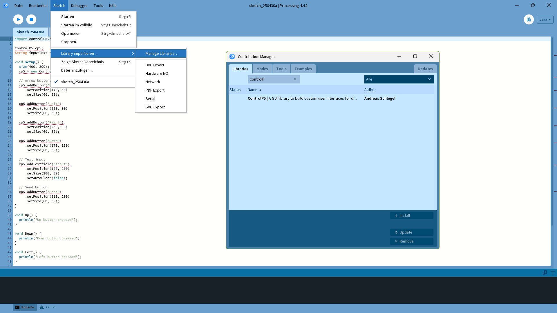
I started the Processing programming by installing the ControlP5 libray by Adreas Schlegel, through the librarymanager(Sketch -> import library -> Manage Libraries)
Code
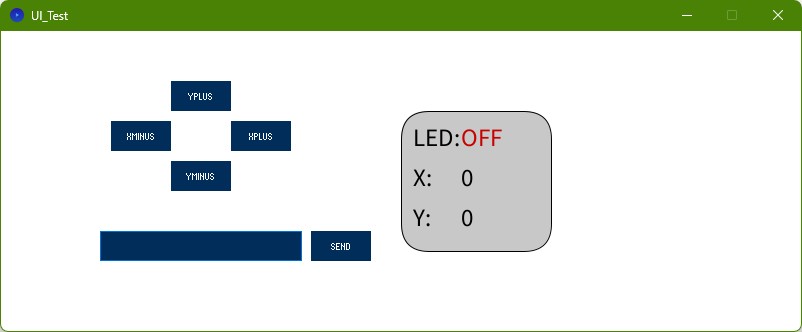
The Main Structure, I took from ChatGPT(Serial and GUI) and added the Status Monitor on the rigth side with the position of the motor in Stepps and the current State of the LED. I also added the right commands, so that the MC knows, what to do.
            import controlP5.*;
            import processing.serial.*;

            ControlP5 cp5;
            String inputText = "";
            boolean light = false;
            int xPos = 0;
            int yPos = 0;

            Serial mechaDungeon;


            void setup() {
              size(800, 300);
              cp5 = new ControlP5(this);

              printArray(Serial.list());  // List all available serial ports
              String portName = Serial.list()[6];  // Select the first available port (adjust index as needed)
              mechaDungeon = new Serial(this, portName, 115200);  // Set the baud rate (must match the device)

              // Arrow buttons
              cp5.addButton("YPlus")
                 .setPosition(170, 50)
                 .setSize(60, 30);

              cp5.addButton("XMinus")
                 .setPosition(110, 90)
                 .setSize(60, 30);

              cp5.addButton("XPlus")
                 .setPosition(230, 90)
                 .setSize(60, 30);

              cp5.addButton("YMinus")
                 .setPosition(170, 130)
                 .setSize(60, 30);

              // Text input
              cp5.addTextfield("input")
                 .setPosition(100, 200)
                 .setSize(200, 30)
                 .setAutoClear(false);

              // Send button
              cp5.addButton("Send")
                 .setPosition(310, 200)
                 .setSize(60, 30);
            }

            void draw() {
              background(255);

              fill(200);
              rect(400, 80, 150, 140, 28);
              fill(0);
              textSize(25);
              text("LED:", 412,115);

              // Show light status
              if (light) {
                fill(0, 200, 0);  // Green for ON
                text("ON", 460, 115);
              } else {
                fill(200, 0, 0);  // Red for OFF
                text("OFF", 460, 115);
              }

              fill(0);
              textSize(25);
              text("X: ", 412,155);
              text("Y: ", 412,195);
              text(xPos, 460, 155);
              text(yPos, 460, 195);


            }

            void YPlus() {
              println("Y+10");
              yPos = yPos + 10;
              mechaDungeon.write("y+\n");
            }

            void YMinus() {
              println("Y-10");
              yPos = yPos - 10;
              mechaDungeon.write("y-\n");
            }

            void XMinus() {
              println("X-10");
              xPos = xPos - 10;
              mechaDungeon.write("x-\n");
            }

            void XPlus() {
              println("X+10");
              xPos = xPos + 10;
              mechaDungeon.write("x+\n");
            }

            void Send() {
              inputText = cp5.get(Textfield.class, "input").getText();
              mechaDungeon.write(inputText + "\n");
              println("Sent message: " + inputText);

              if(inputText.equals("ON")){
                light = true;
              }
              else if(inputText.equals("OFF")){
                light = false;
              }
            }
.pde file
Result
Problems with the Board
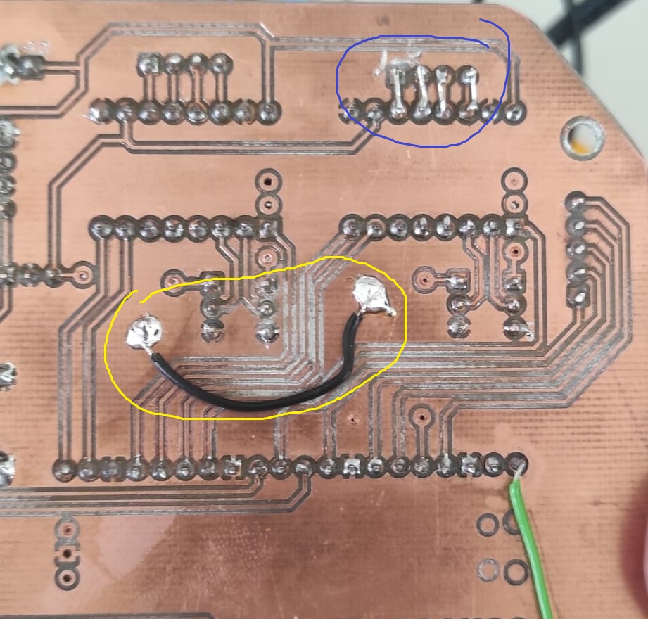
while trying to get the Motors to work, i found out, that i had two problems. Problem one was that the Y-motor was not turning at all and there was no current draw related to this Motor. So inspected the solder joints of the Y-Motor area. The problem was found fast. The nearly every Solder pad of the motor connector was either lifted or ripped off. The second problem after fixing Problem one, was that there was no GND connection of the GND-plane inside the Y-Motor-Driver Area. This prevented the connection of the jumper for the Microstepping of the Y-Motor to be pulled to ground and therefor to go with full steps on the Motor.
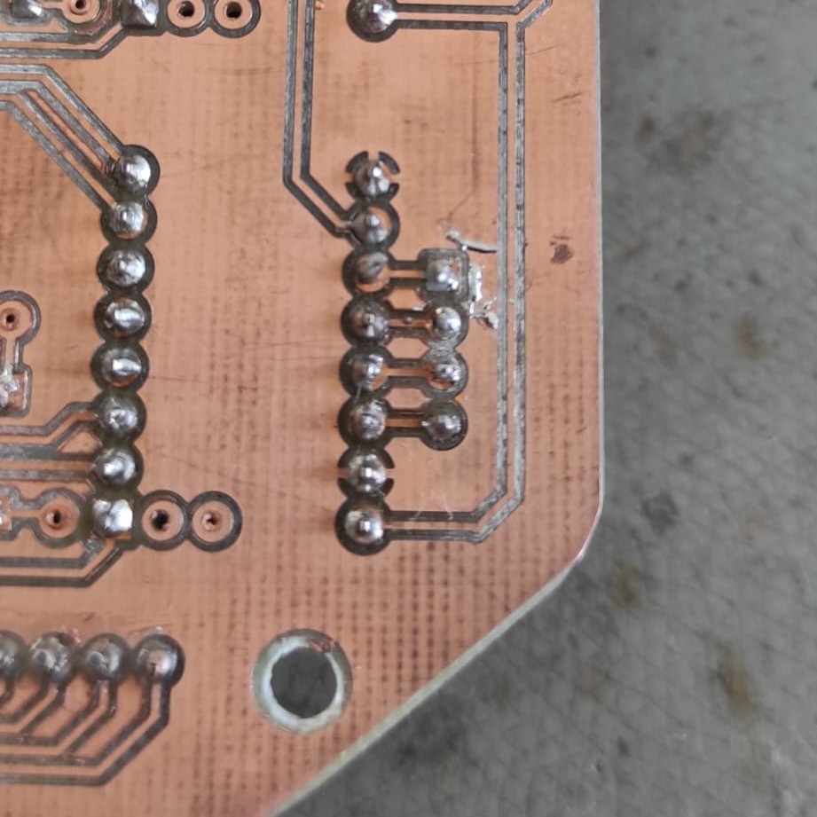
The Fix where simple. I first bridged the Motor and Driver connection with small pieces of wire(blue). The second problem was solved by soldering a wire from the GND-plane of inside the X-Motor-Driver area to the one of the Y-Motor-Driver area(Yellow)