Assignments
- design a machine that includes mechanism+actuation+automation+application
- build the mechanical parts and operate it manually
- actuate and automate your machine
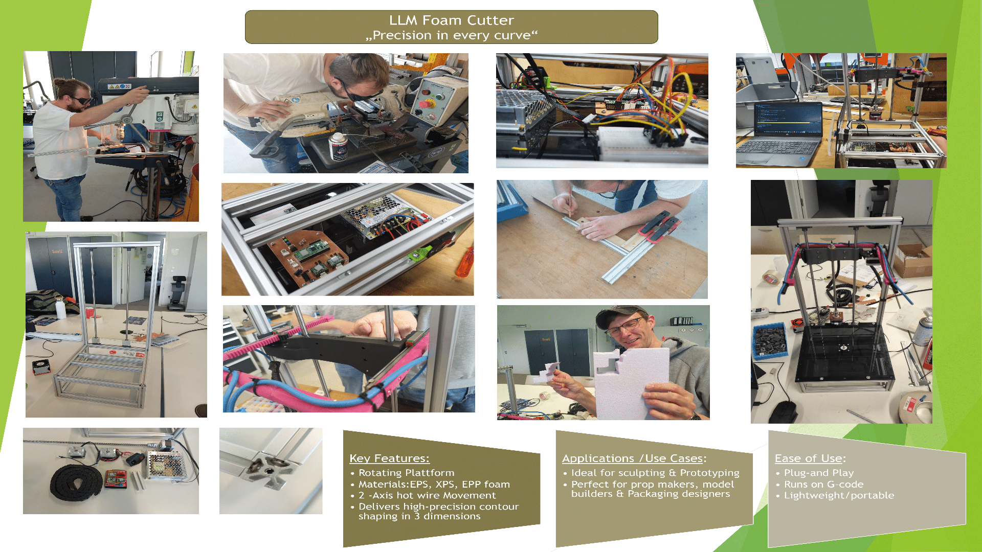
Hero Shot: The LLM-Cutter
Hero Shot: Poster
Introduction
For this assignment, we were challenged to build a machine, and Lysander immediately thought of a hot wire foam cutting system. Our design features three stepper motors: one for controlling the vertical (z-axis) movement, a second for adjusting the cutting depth of the hot wire along the x-axis, and a third for rotating the base 360°, which holds the material. This configuration allows for precise cuts and efficient foam shaping while maintaining stability throughout the cutting process. As for the name of our machine, we took our initials to represent the fact that it is our combined efforts led to our great machine, the so called LLM Foam Cutter :P
LLM Foam Cutter's Roadmap
In order to have a clear vision of the necessary steps to complete our LLM Foam Cutter Machine, we used Miro to have a proper overview of the tasks sequence.

Work Packages Division
Work packages |
Responsibility |
|---|---|
| 3D Modeling | Mika + Lysander |
| Manufacturing | Mika + Lysander |
| Programming | Leen |
| Wiring | All |
| Assembly | All |
| Testing | All |
| Debugging/Improving | All |
| Project Management | Leen |
| Poster | Lysander |
| Video Edit/ Videography | Lysander |
| Documentation | All |
3D-Modeling
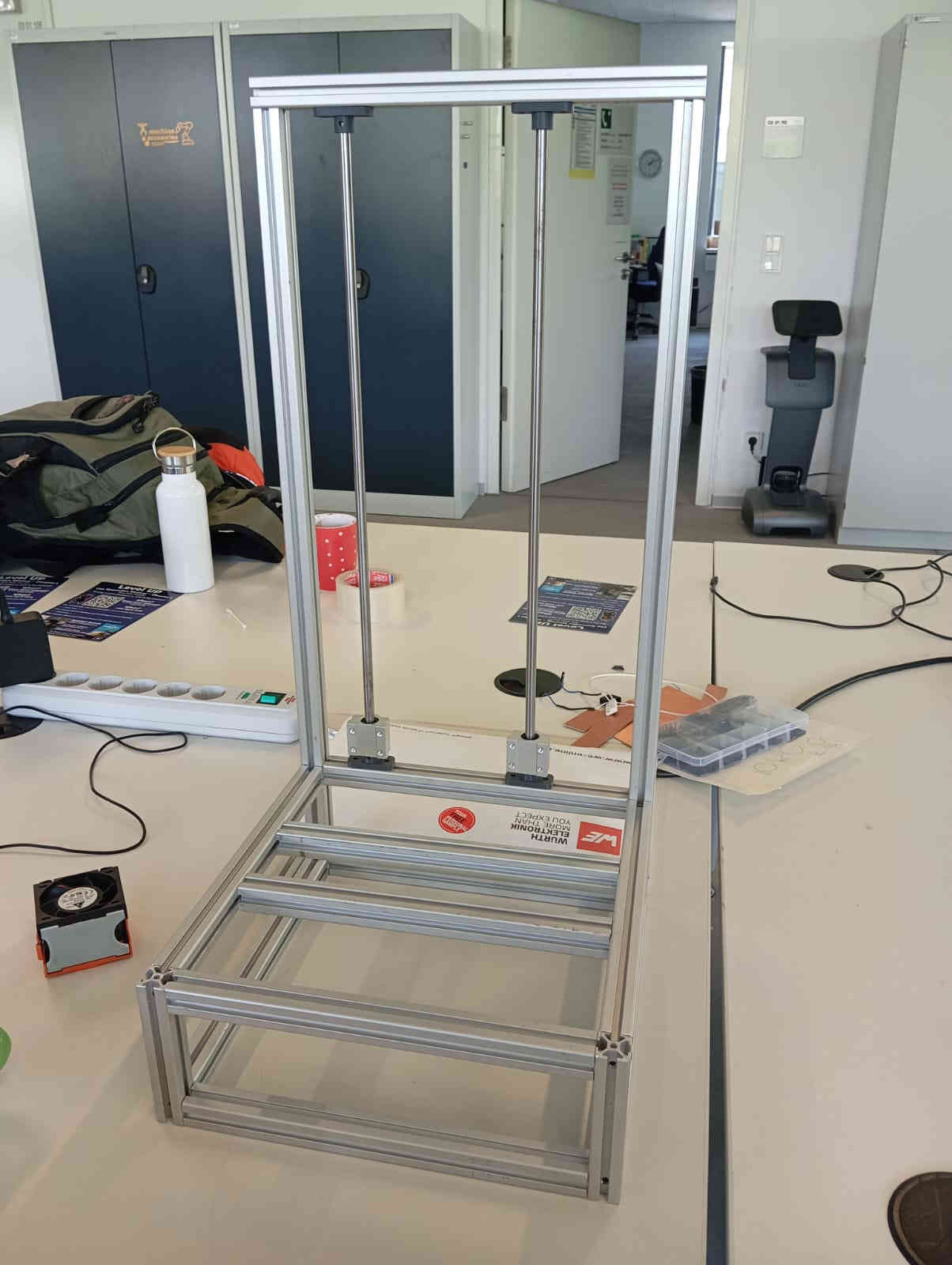
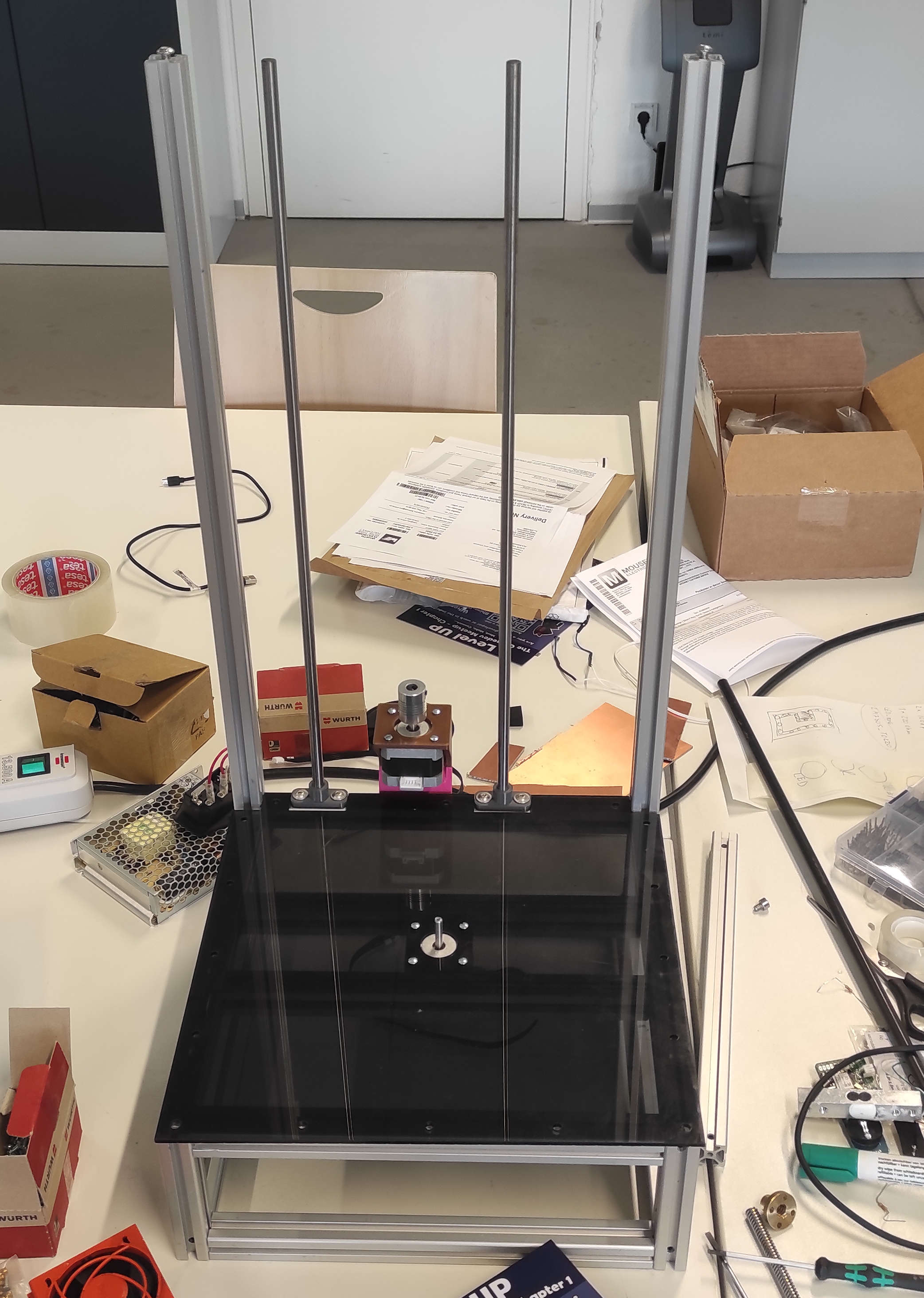
Frame
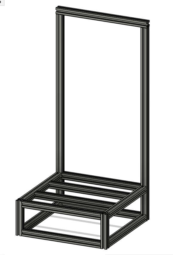
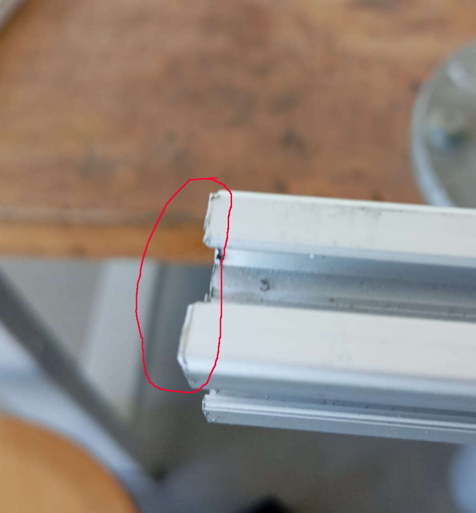
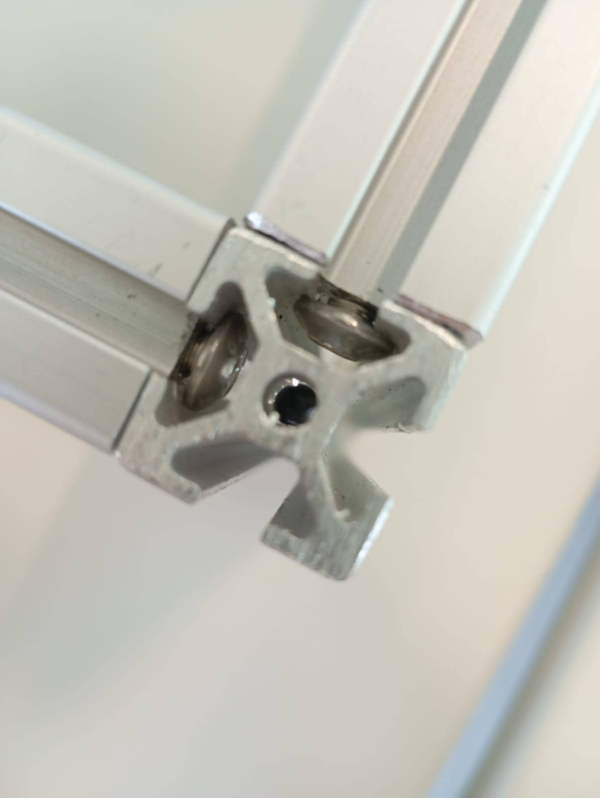
The Frame was build out of 2020 Aluminum Profile with a 5mm Slot, because we had this on hand. The dimensions where chosed based on pre cut Profiles laying around to reduce the number of cuts to make. We went with a base dimension of 630mmin heigth and 300mmx300mm as a square base. For joining the profiles, we went with a technique called Blind joints.
Bildjoints
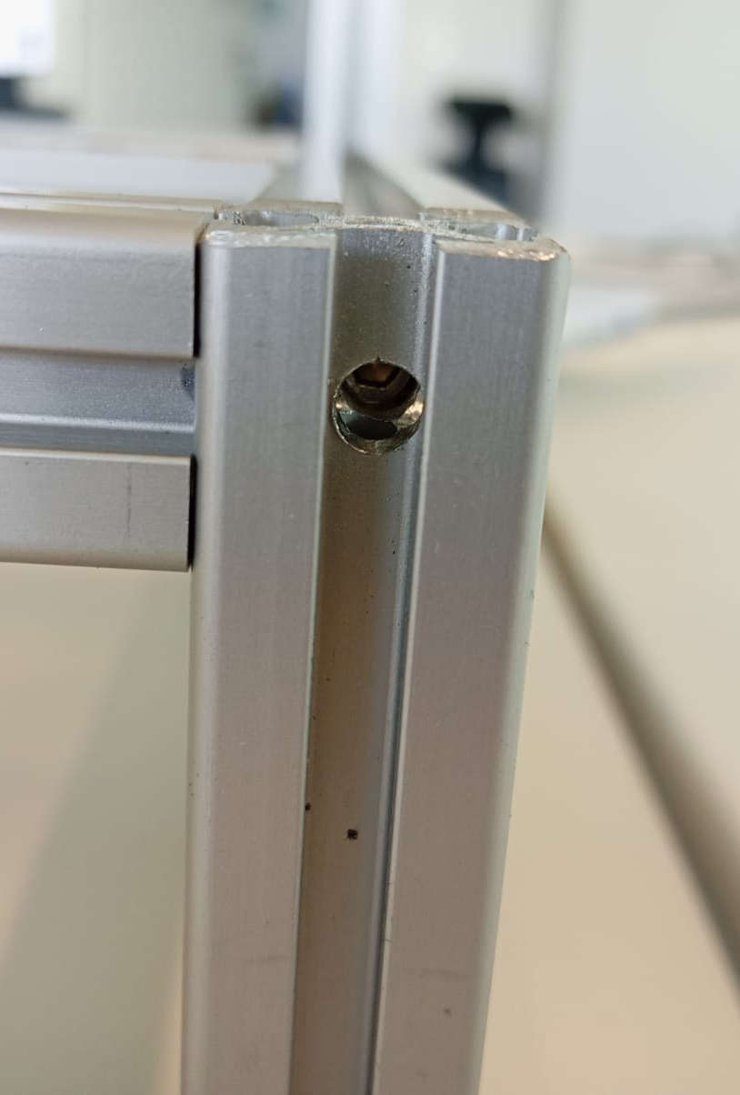
Blind Joints is a technique that takes advantage of the profile's internal slot. In our case, we tapped the ends with an M5 thread and used M5x16mm screws on one profile. On the mating profile, we made a 5mm hole for a hex key to pass through. During assembly, the screw head is slid into the slot and then tightened using the hex key through the 5mm hole. This creates a clean, strong joint without the need for external brackets.
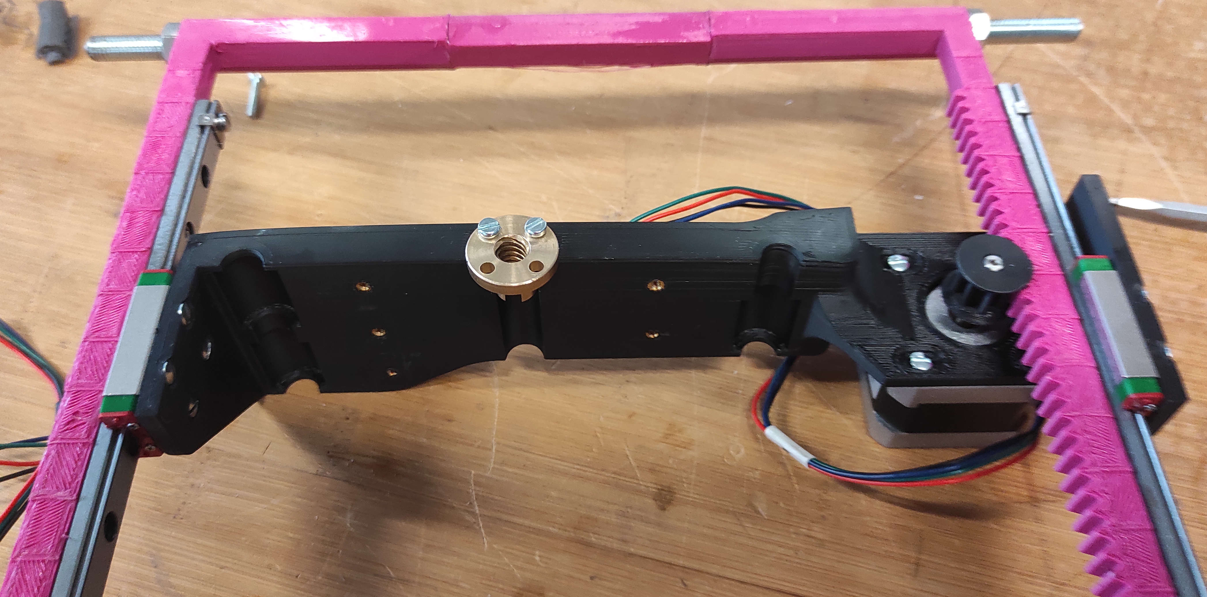
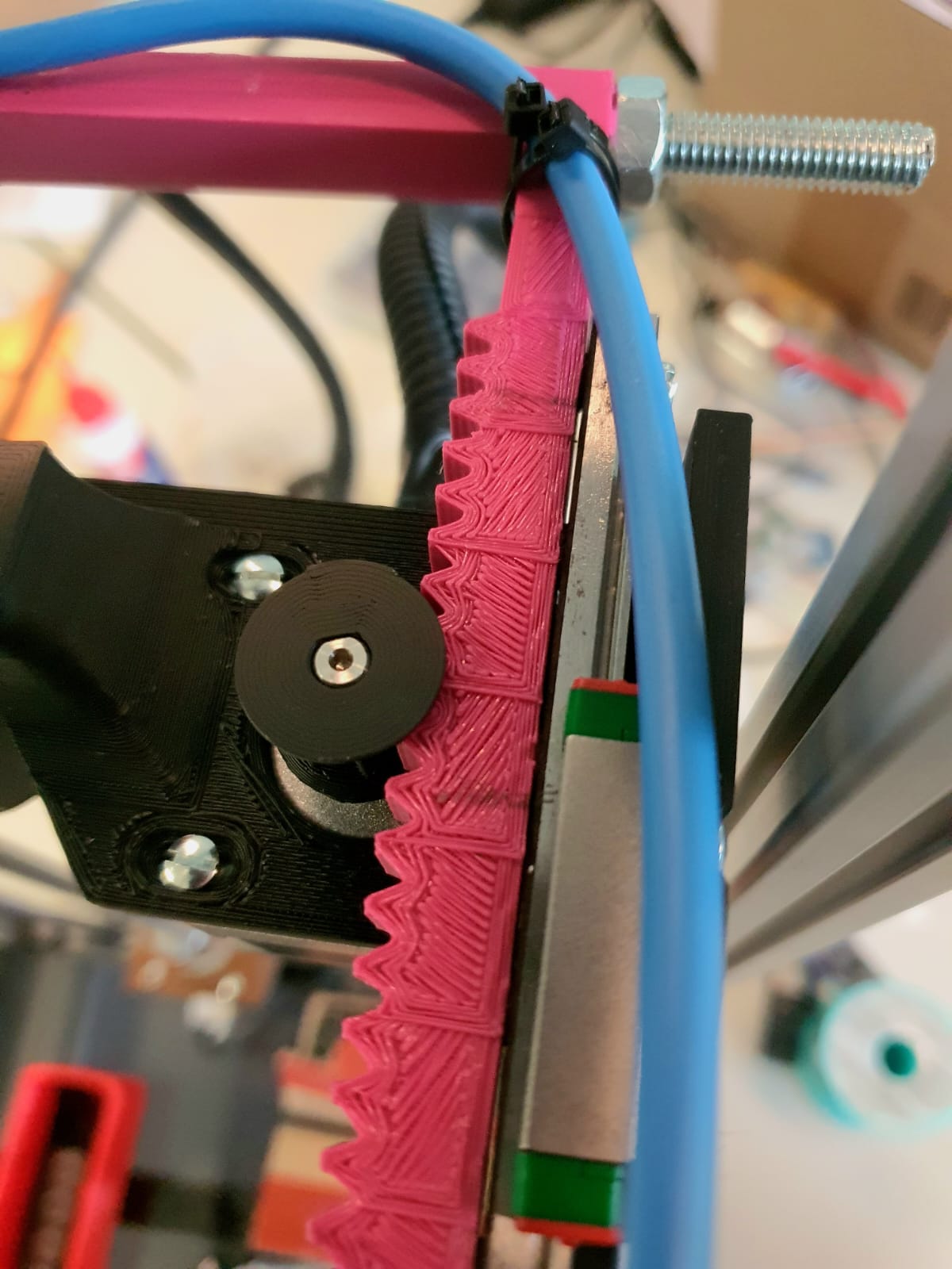
X-axis
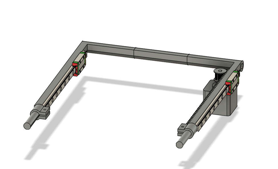
For the X-Axis for stability we used mainly the MGN9C Rails and a 3d "bow", which we needed to print in 3 Parts to fit it on our Printers, because even the largest Printer(except the BigRep, which's print quality wouldn't be fine enough) in our Lab were to small for the not splitted part. for At the end of the "bow" we added 60mm long carbon fibre rods, as insulator for Heat and also for the power. The rack is 9mm in width, so it fits snuggly with the MGN9 Rail. For the Pinion, we made the gear part 10mm to have so wiggleroom and also capped the ends, so it wont slide off the rack.
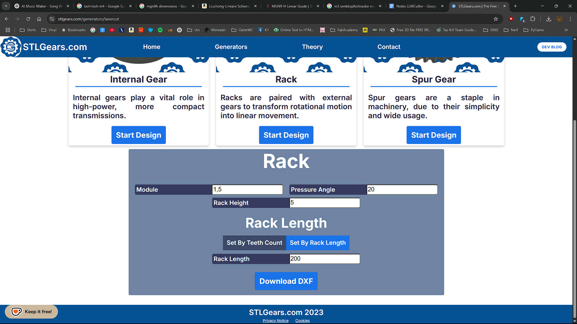
Rack and pinion
For the Rack and Pinion i used the DXF generator on stlgears.com and then imported the dxf into fusion and extruded the profile to have Rack and pinion.
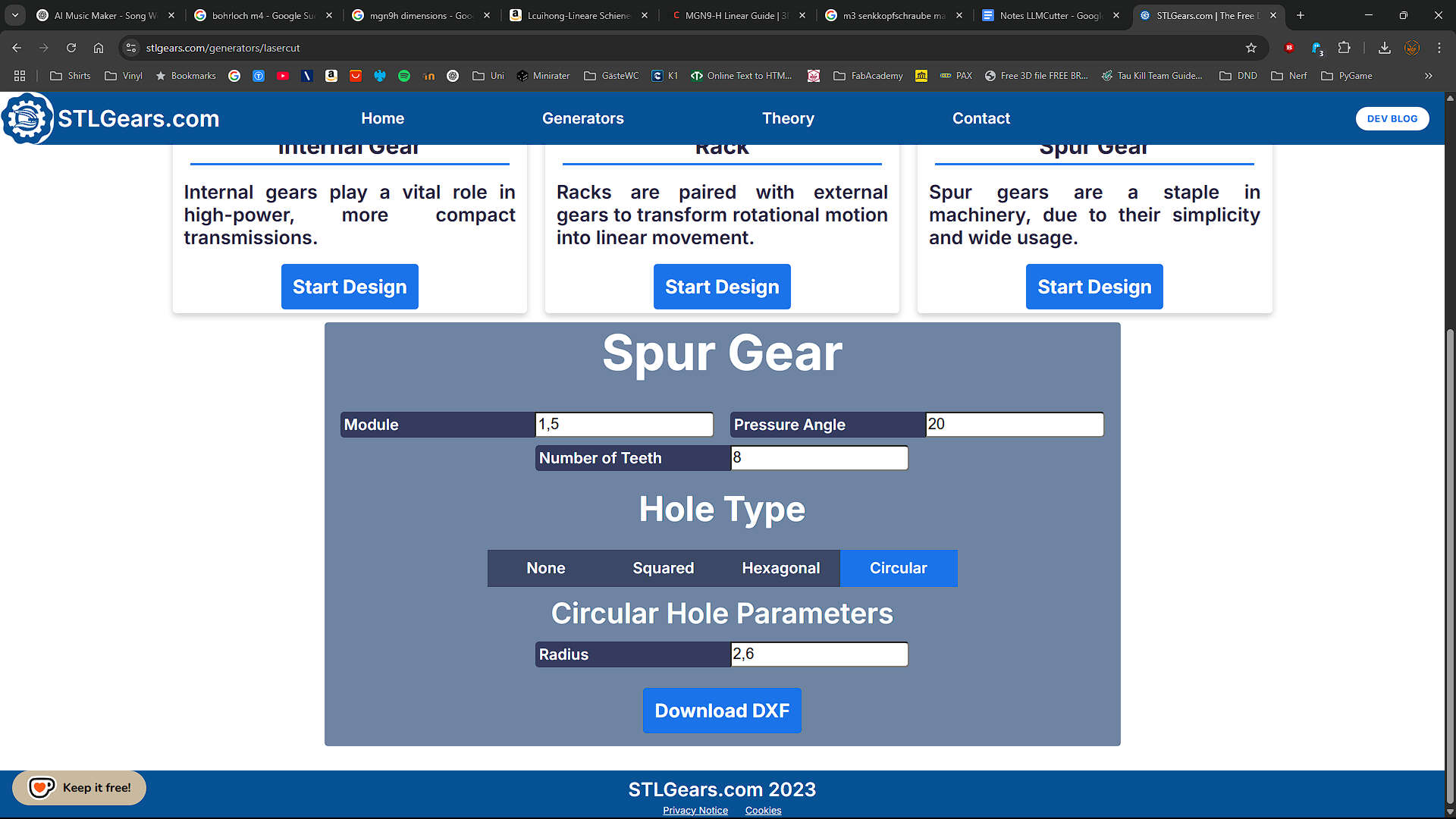
Pinion Settings: Spurgear with a module of 1.5mm, a pressure angle of 20° and 8 teeth. Circular hole with 2.6mm radius
Rack Settings: Rack with a module of 1.5mm, a pressure angle of 20° and 5mm rack heigth. Length is 200mm
used Models
For reference while modeling the X-Axis, I used the MGN9-H Linear Guide by Lehaiver
Y-axis
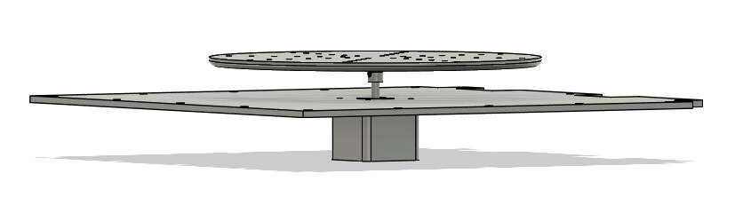
The Y-Axis is pretty simple. Its just the Top Cover where the motor is attached to and then the Rotor Table Placed on the Motor
Z-Axis
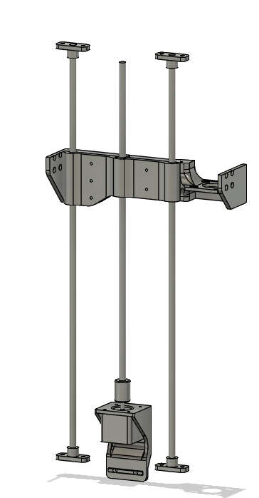
We started with the Rodholder and duplicated them to the respected places. The right rod is shifted to the left, to make space for the X-Motor. The Z-Motor is held by a printed part located directly at the middle between the rods, where also the the Leadscrew is Attached sccrew. The carrier houses 3 LM8UU Bearings, two placed on the left and one on the right rod. on the outer sides the MGN9-H Carriers are attached so in that case they are our stationary part. The Xmotor with the XPinion are located between the right MGN9 Rail and the right Z-Rod.
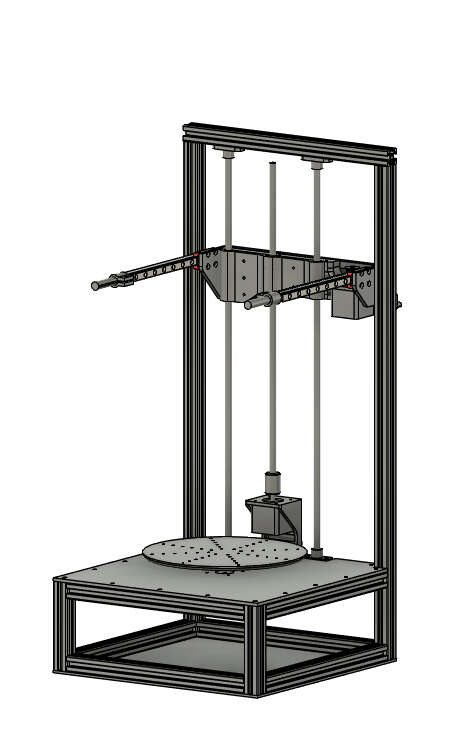
Completed 3D-Model
here you can see the whole 3D-Model
Downloads
F3D archive production filesAssembly
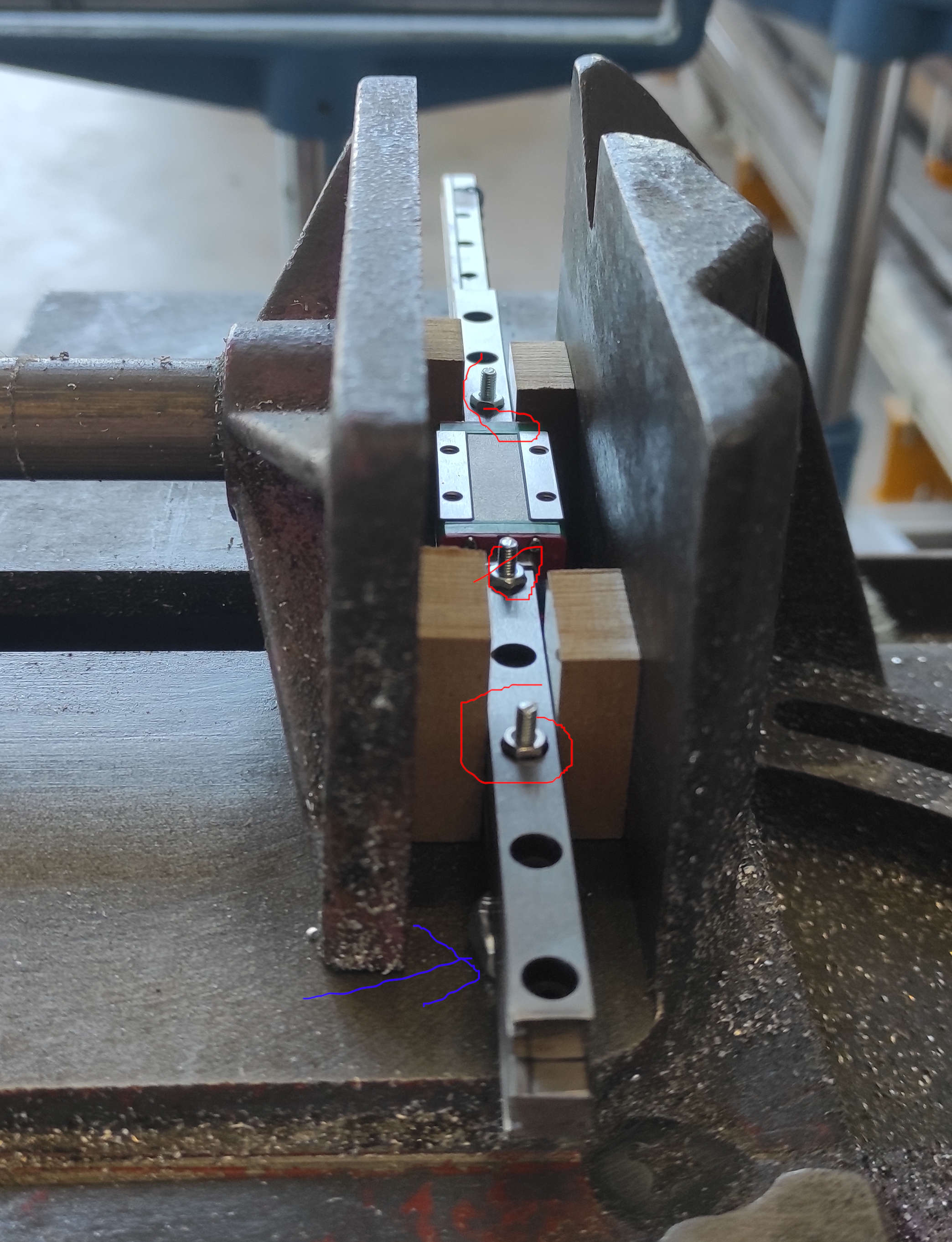
Cutting the MGN9 Rail
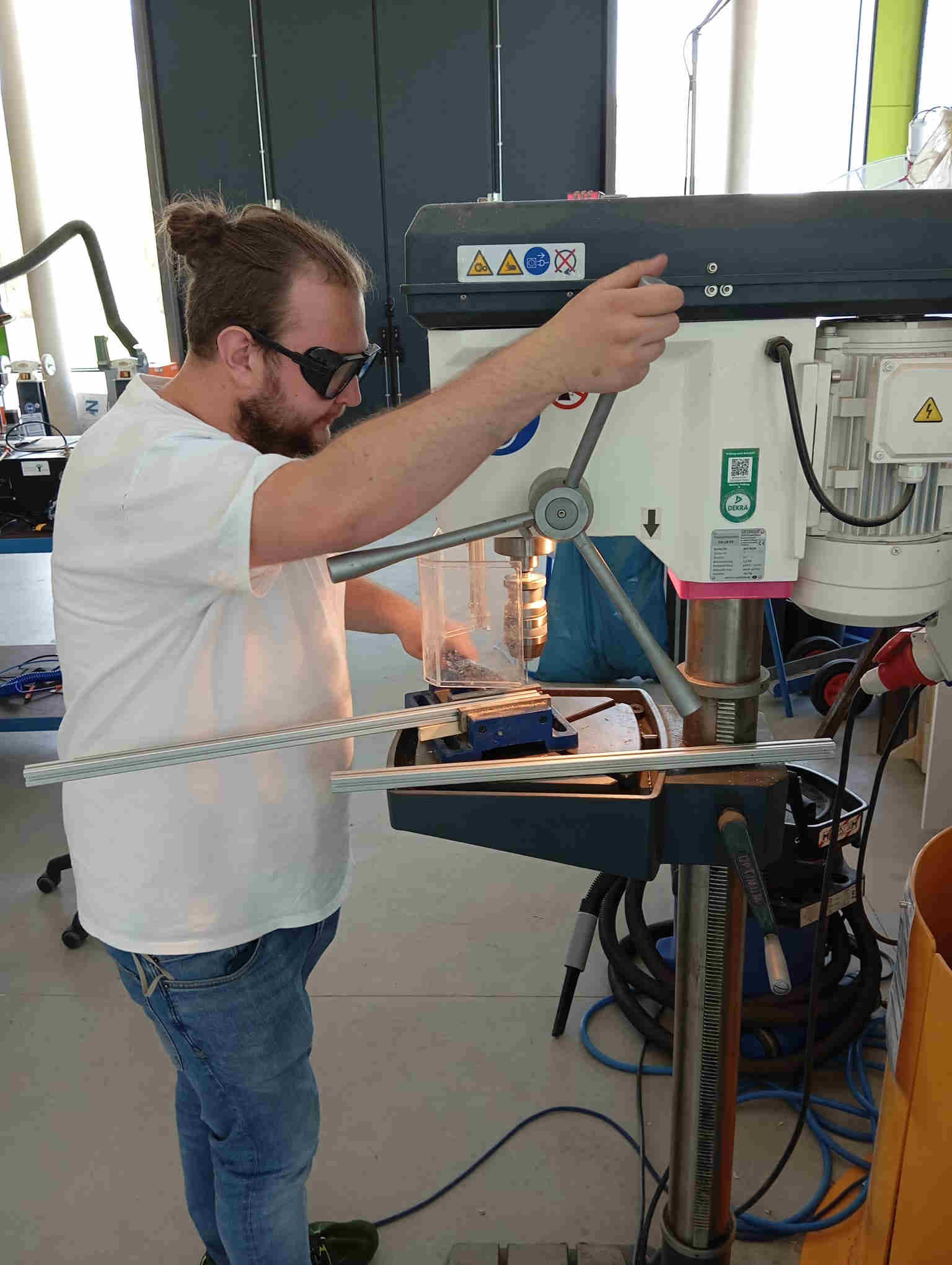
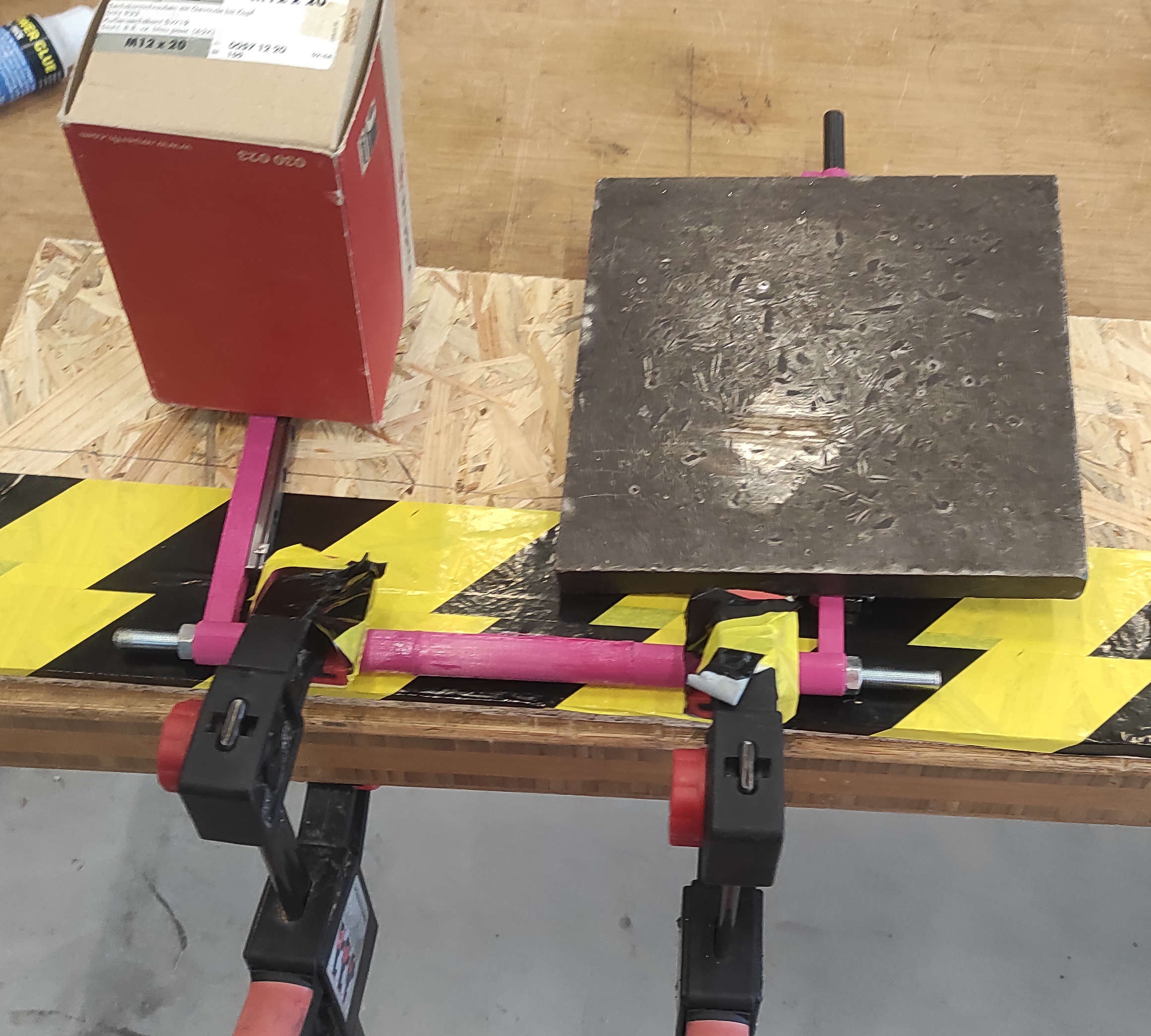
We had one precut MGN9 Rail with 200mm on hand, so that we needed to cut the other to the same length with the same hole Pattern. For that we screwed the two rails together with some m3 screws and nuts(marked red), clamped them with some wooden blocks on the side, so that the carriages where able to move freely and are not pressed. To rise the rails from the bottom we used 2 M8 nuts, one marked blue in the front and one is in the back, which is not vissible. we used the top rail as guid for the band saw. after the first cut was done, we turned the rails around and cut the other side.
Frame
We started measuring and cutting.
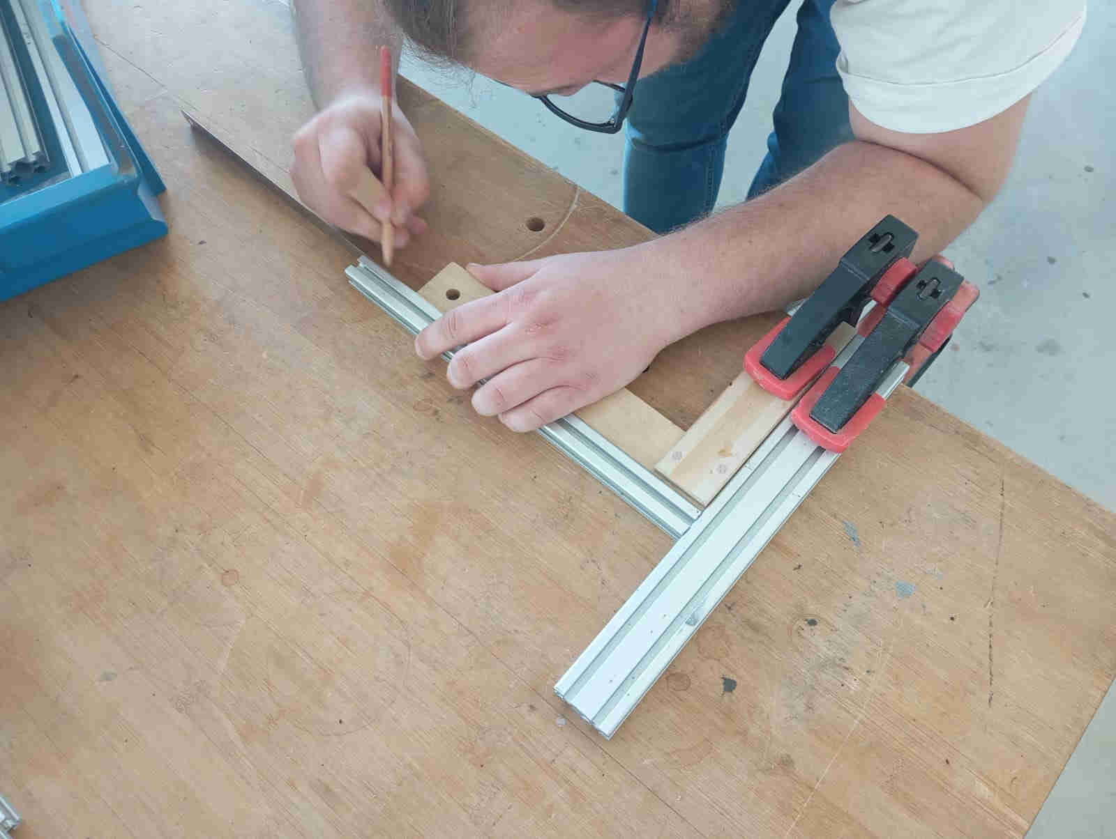
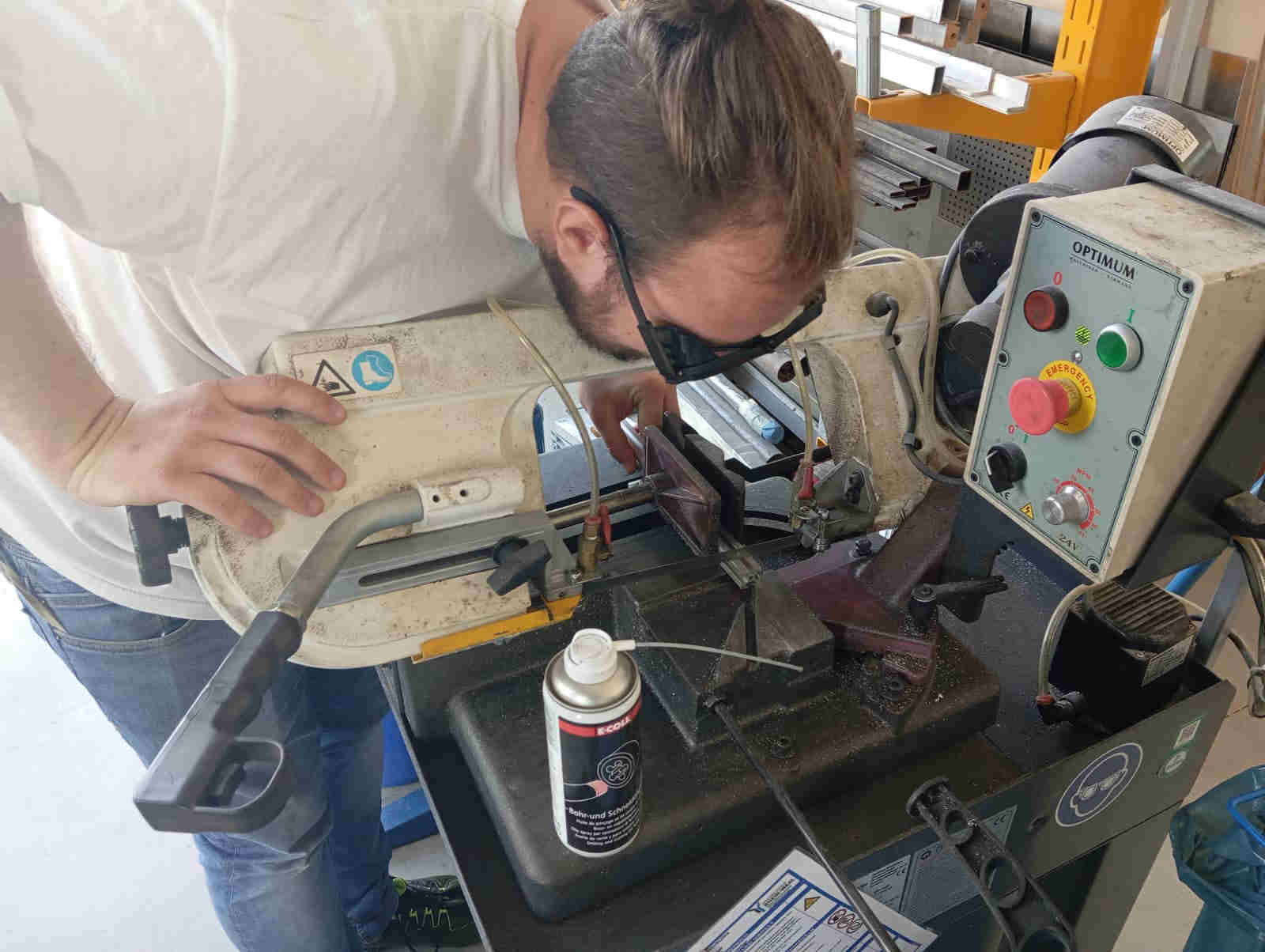
Once all the parts had all the sharp edges removed with file, we marked out where we needed to drill holes
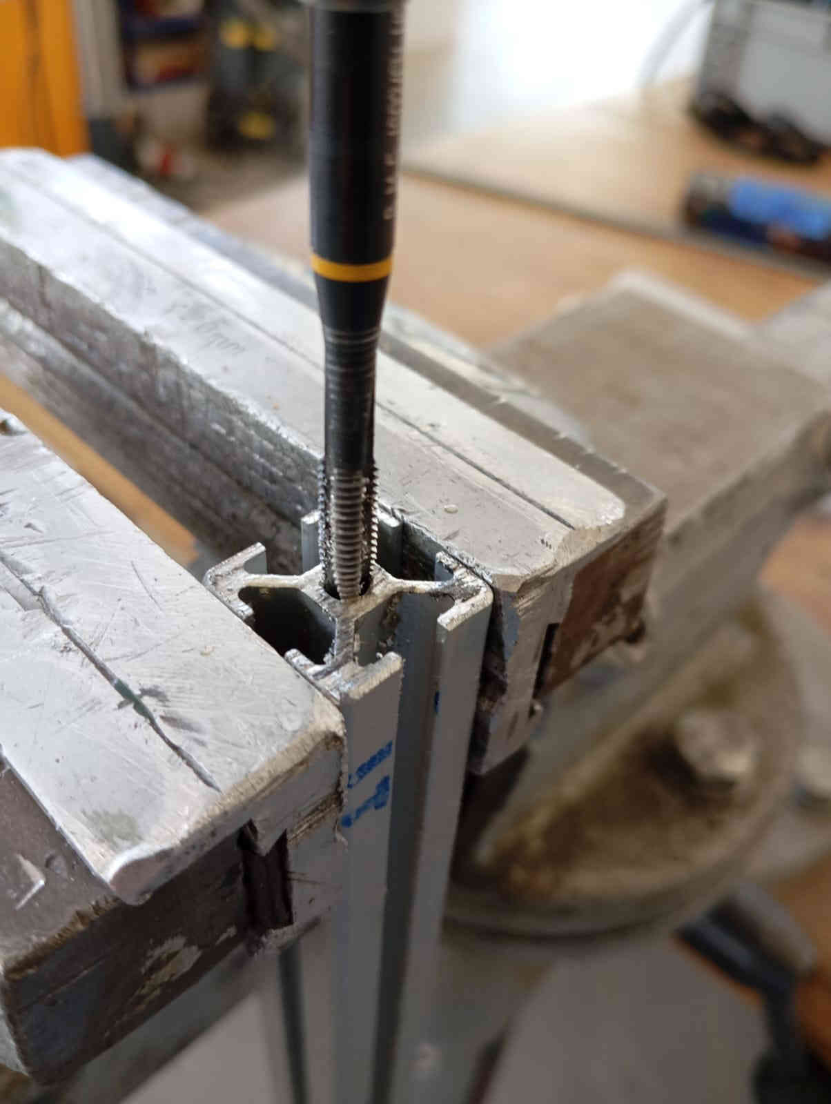
and cut the threads for the
assembly of the frame. Mika got stared on the drilling of the holes while I started on cutting the threads
and filing down any sharp edges.
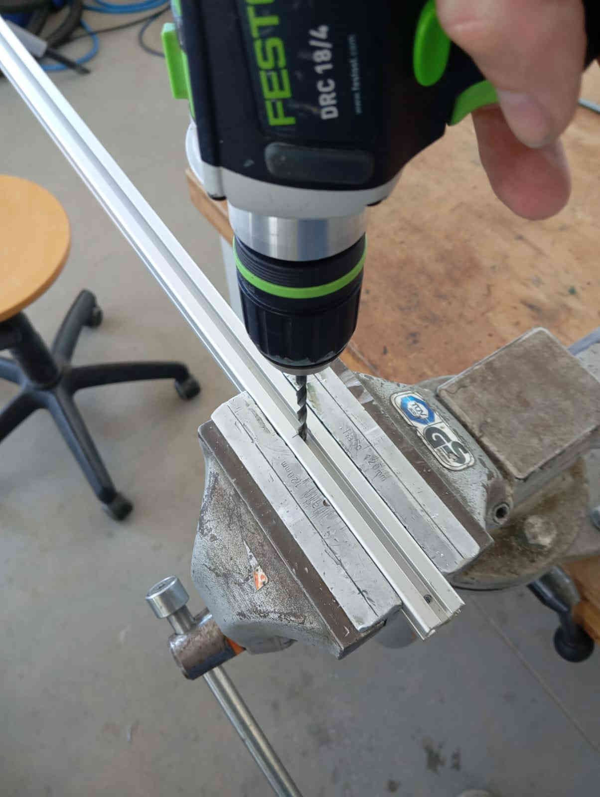
As I also wanted to join in on the fun of drilling I got the hand drill and started on the smaller parts.
We thought of using 45° degree angles to join the Aluminum extrusion, but the look was not right. This is
what we drilled and tapped the frames parts.
This let us a bolt with wider head to slid in with the head of the screw onto on of the Aluminum extrusion
and screw all the parts together.
The smaller holes where drilled so that an Allen key could fit to tighten the button bolt down. Letting the
frame have a very clean look.
Profiles:
- 2 x 610mm
- 2 x 110mm
- 10 x 260mm
- 1 x 300mm
other parts:
- 14x M5x16 Socket Button Screw
X-Axis
- Print the Parts
- Melt heat inserts into both sides of the XCarrier to screw the Rail onto. like this:
- Screw the Rails to the sides
- Glue all 3 XCarrier parts together. I used 2k Epoxy to glue everything together and a 8mm rod with Nuts for stability
- Screw the MGN9-C Rails onto the XCarrier(and if not already done like it was already by us, put the carriage onto the Rail)
printed Parts:
- 1x XCarrier L
- 1x XCarrier R
- 1x XCarrier Mid
other Parts:
- 2x MGN9R 200mm linear rail
- 2x MGN9H Carriage
- 20x Ruthex RX-M3x5.7
- 20x M3x10mm Socket Cap Screws
Y-axis
The Y-Axis was straight. . We just printed and laser cut all pieces, then screwed the Motor to the TopCover(with the Socket cap screws) with the cable orientating to the rigth(blue Arrow) and screwed it with the 4 (red) marked holes to the Frame with the m5 nuts and Screws.
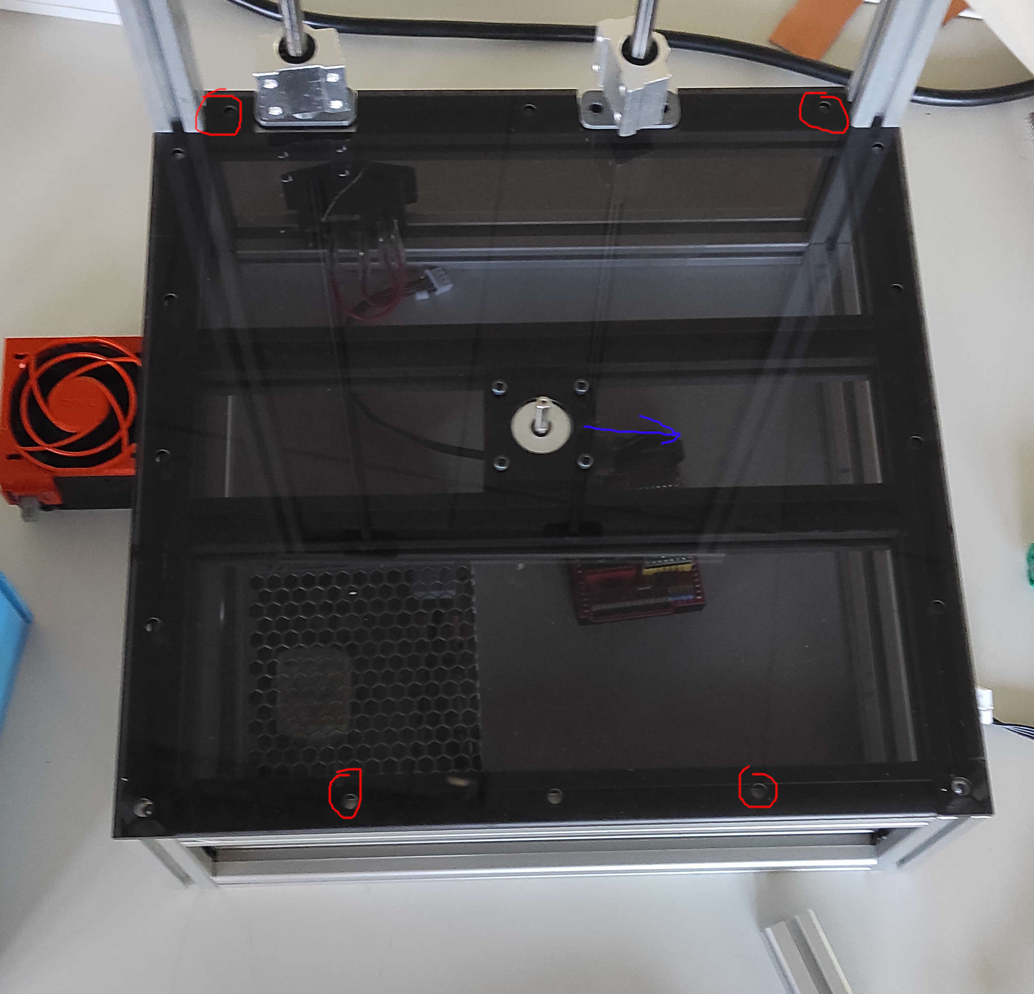
last step for the Y-Axis was to put on the RotorTable
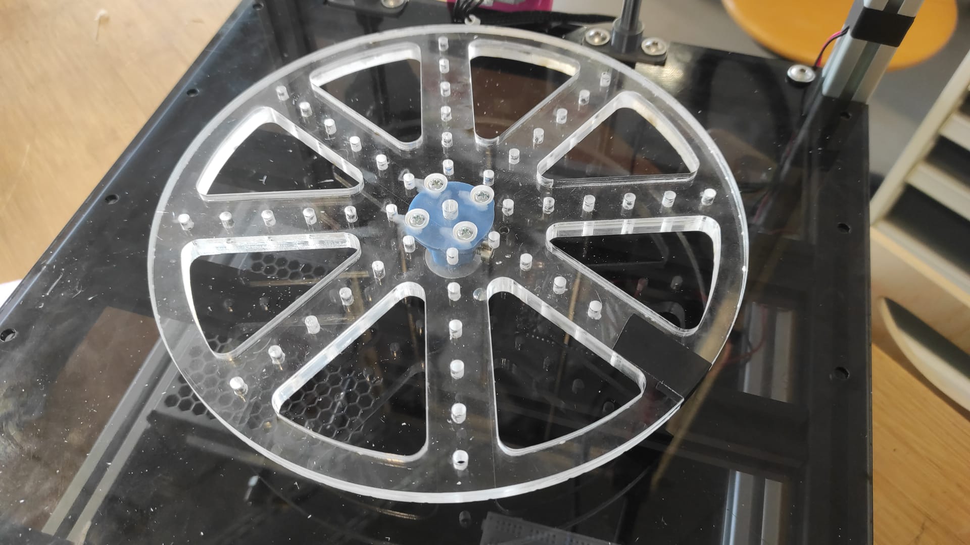
We have a different Rotor Table, more information later in the documentation
printed/lasercut Parts:
- 1x TopCover (4mm PlexiGlas)
- 1x RotorTable
other Parts:
- 1x Nema17 Motor
- 4x M3x8mm Socket cap screws
- 4x M5 Slot5 SlotNut
- 4x M5x10mm Socket Button Screw
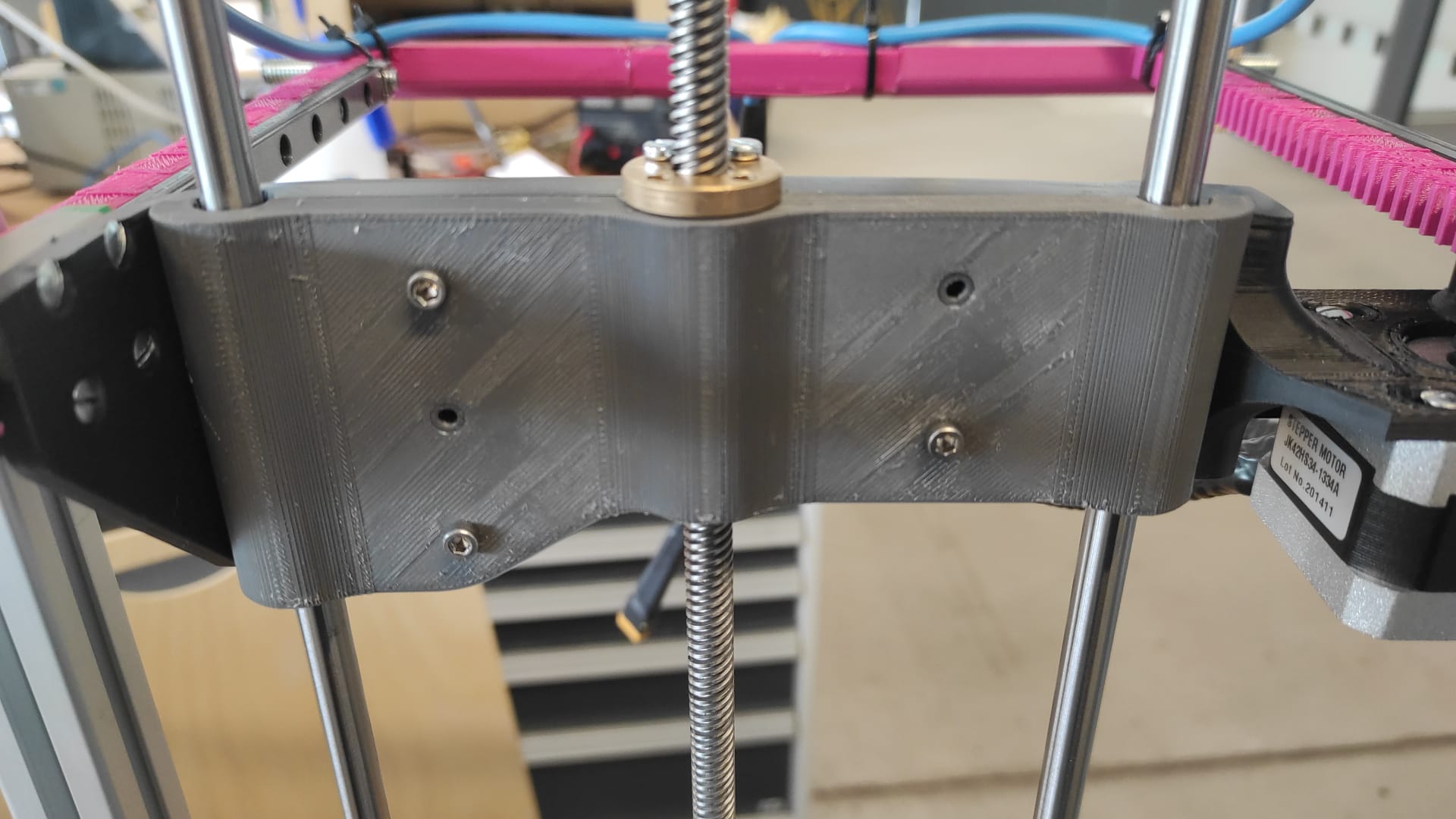
Z-Axis
- Print the Parts
- Removed the top Frame Piece
- Screw the bottom ZRHolder into the notches from the TopCover. Also Insert the ZRods.
- Assembled the ZassHolder with the motor(with the Socket cap screws), attached the flex couppling to the motor and mounted the Assembly to the frame in the middle between the the two ZRods.
- inserted 5 Heat inserts into the Z-CarriageA
- Screwed the X-Axis to the Z-CarriageA with the countersunk screws.
- placed the XPinion onto the rack before screwing the second motor to the Z-CarriageA. Putting the XPinion on the motor before screwing the motor to the Carriage wouldn't Work
- screw the Leadscrew nut onto Z-CarriageA wit the first 2 M3x20mm Screws
- put 2 LM8UU Bearings onto the left and one on the right Zrod.
- screwed the Leadscrew into the nut
- placed the bearings into the corresponding places in the Z-CarriageA
- Close the Z-Carriage with Z-CarriageB(M3x16mm Socket Cap Screws) also screw the last 2 M3x20mm of the Leadscrew nut to the Z-Carriage
- Secure the LeadScrew in the Flex Coupling
- Put the top Frame piece back and secure the
printed Parts:
- 1x XPinion
- 4x ZRHolder
- 1x ZassHolder
- 1x Z-CarriageA
- 1x Z-CarriageB
other Parts:
- 2x Nema17 Motor
- 8x M3x8mm Socket cap screws
- 1x 8mm Leadscrew plus 1x nut
- 4x M3x20mm Socket Cap Screw
- 8x M3x8mm countersunk screws
- 3x LM8UU Linear Bearing
- 5x Ruthex RX-M3x5.7
- 5x M3x16mm Socket Cap Screws
- 2x M5 Slot5 SlotNut
- 2x M5x10mm Socket Button Screw
- 1x 8mm 4way Leadscrew 400mm length
Cutting Wire
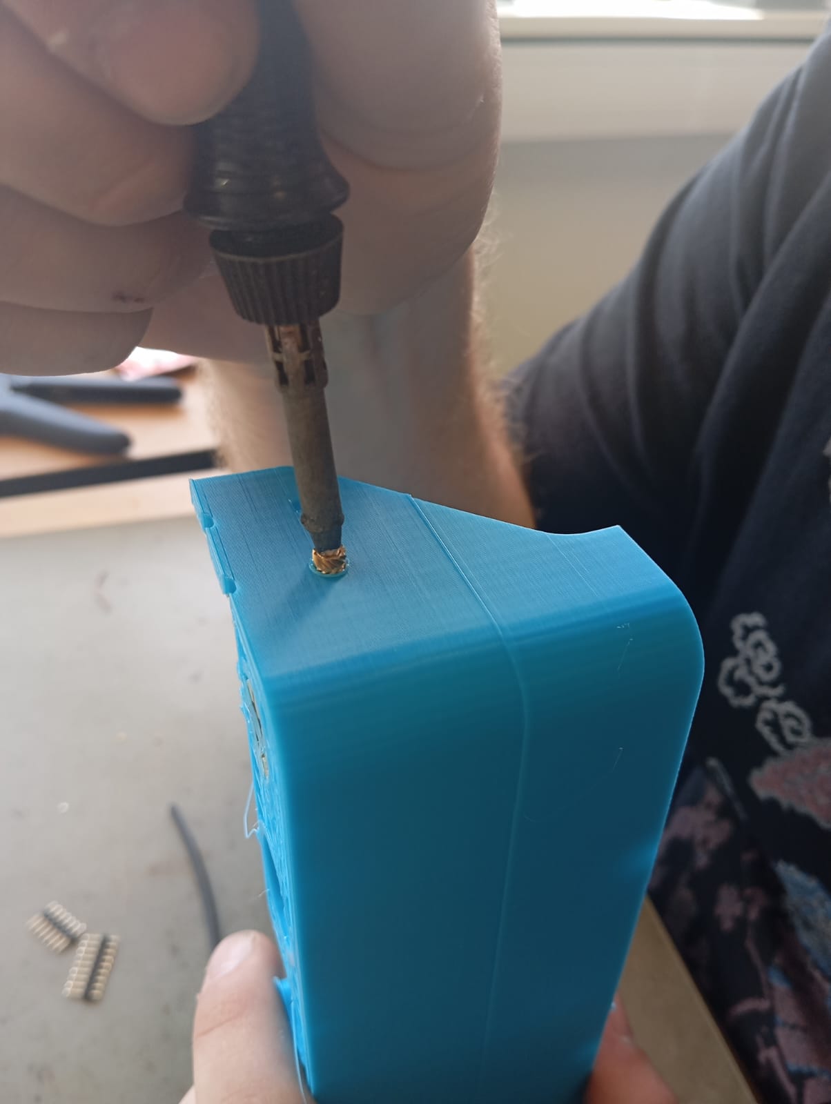
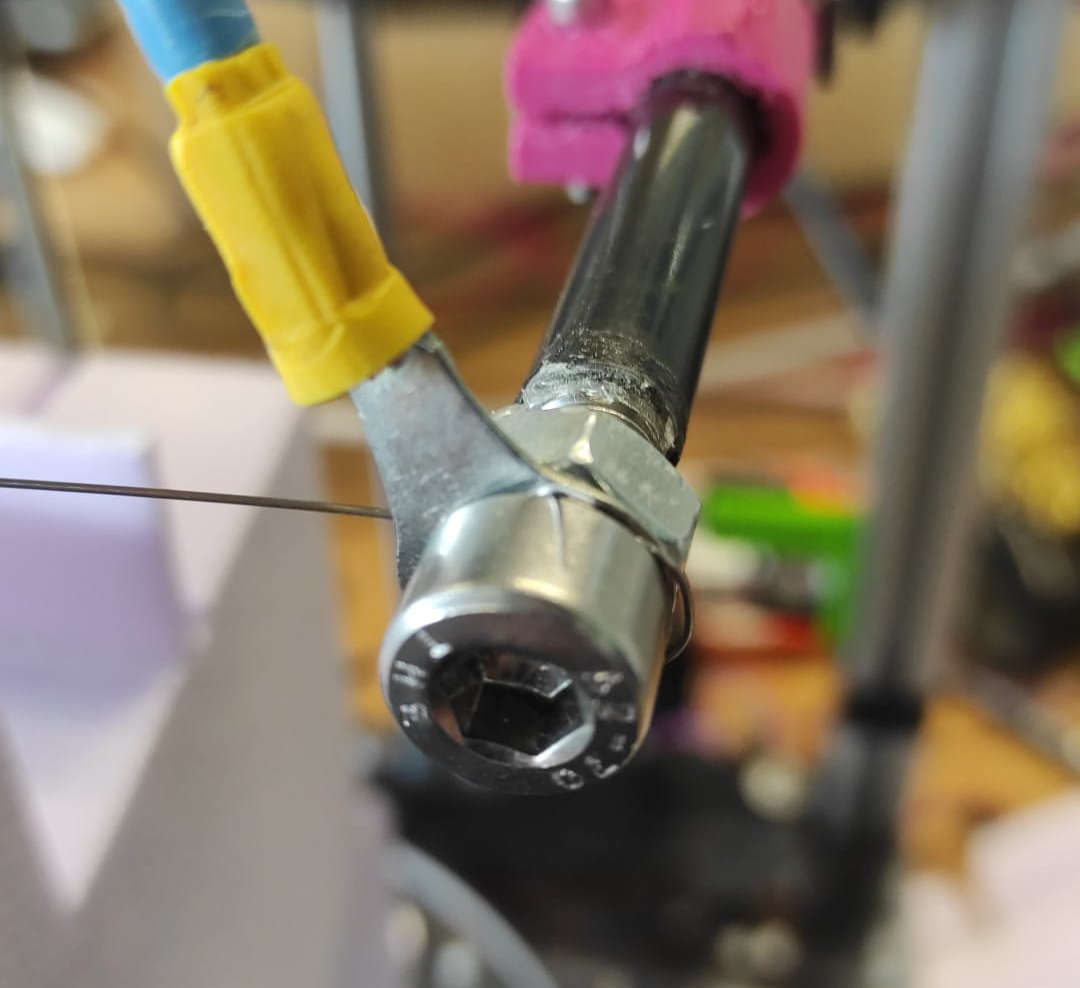
We started by Crimping the 9AWG Wire with the cable lugs. Then putting them onto the m8 Screws with nuts. These Srews were then glued with 2k Epoxy into the Carbon rods with 20mm thread exposed.
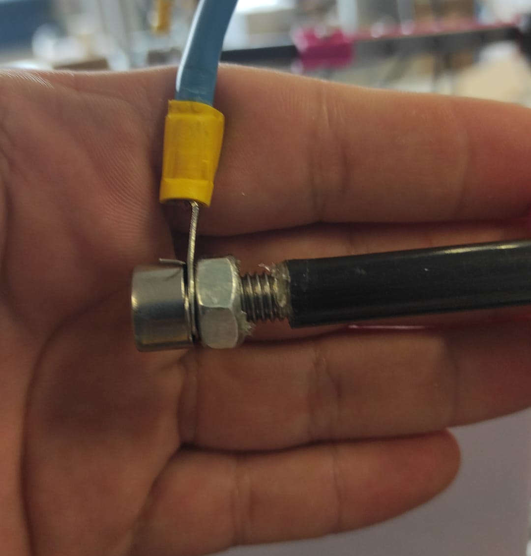
After drying, we inserted the tubes into the tube Holder and secured them with the M3 Nuts and Screws. The last step was to put the Cutting Wire. 0,5mm V2A Stailess Steel wrapped around the screw and then secured with theM8 Nut.
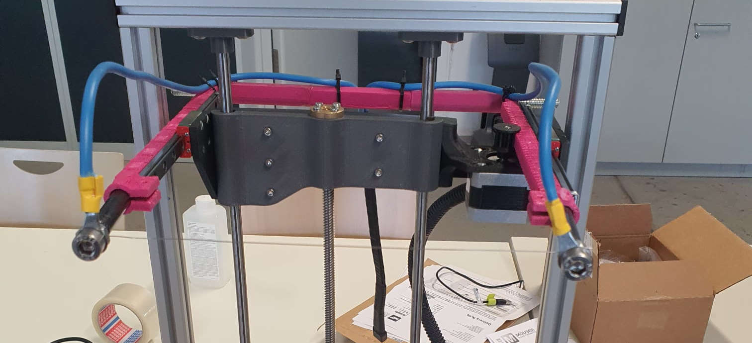
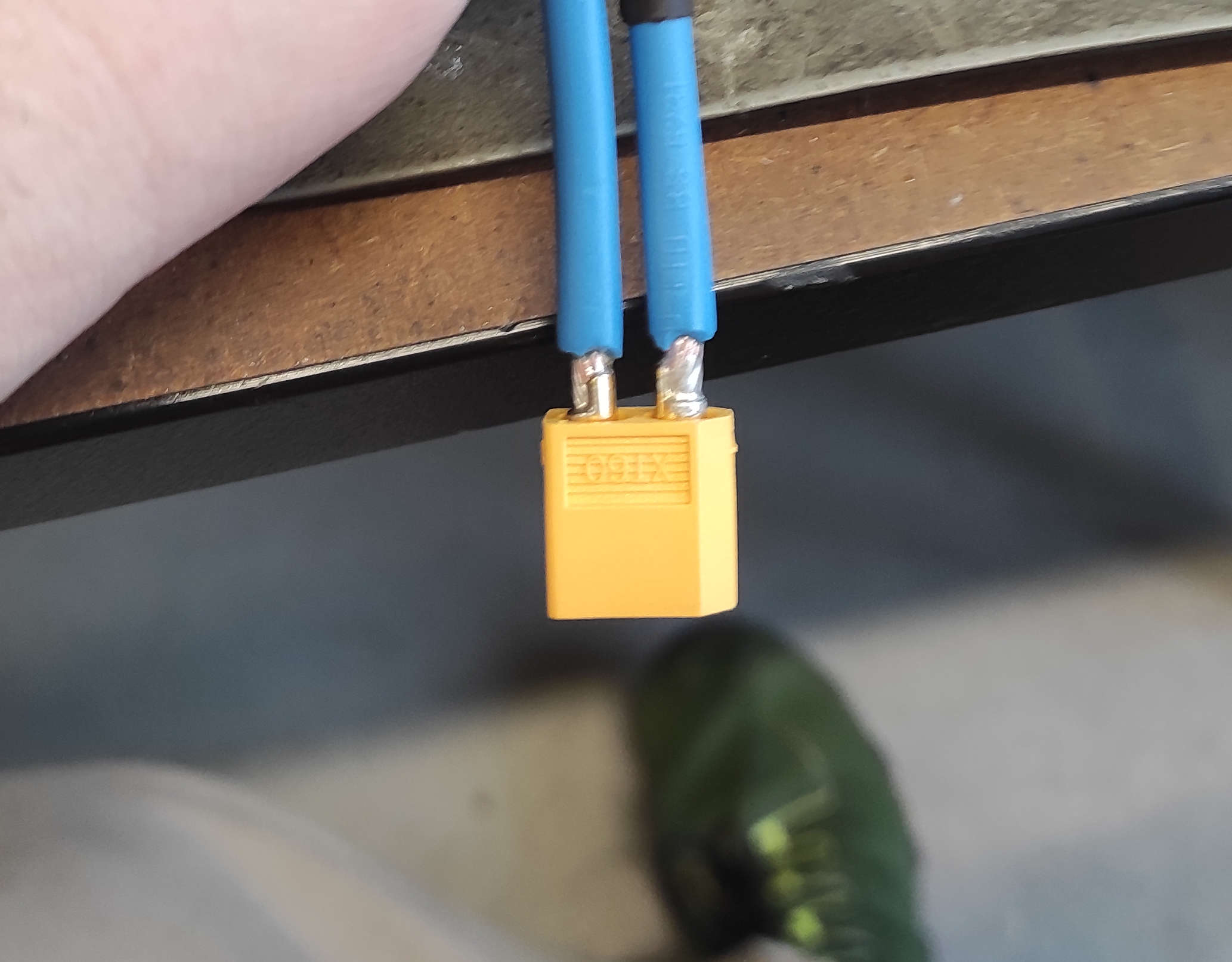
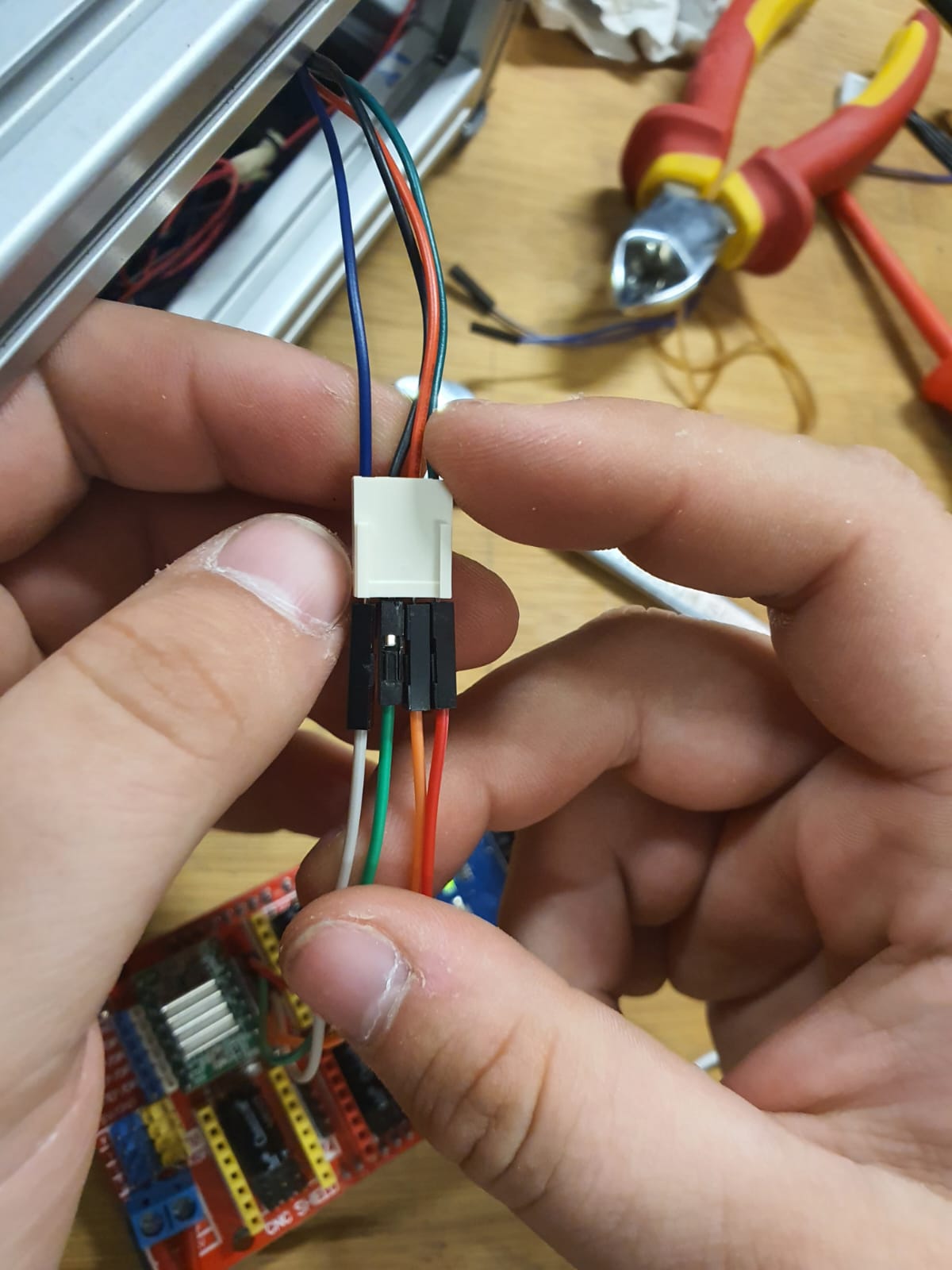
Now we are going to the back. We needed to solder a connector, so we can move the hole assembly easy and handle the Test setup easier. We used an XT60 connector usaly used to connect lipo Batterys to applications where a high powerdraw occures. We used smaller Shrinking Tube to cover the soldered connection and a bit larger one to tigthen up the backside for cable management. With zipties, we did the cablemanagement along the "Bow"
other Parts:
- 2x M8x40mm Screws
- 2x M8 Nuts
- 2x M3x20mm Screws wih nuts
- 2x 10mm Carbon Tube with 60mm length
- 9AWG/6mm^2 Wire
- 2x 6mm^2 loop cable lugs with 8mm hole
- XT60 Plugs
- zipties
- Shrinking tube
Changes in the Prototype
What didn't occure in the 3D-Model:
- The Endswitches
- cablemanagement
printed Parts:
- 1x CableHolder
- 1x ZSwitchHolder
other Parts:
- 2x Endwswitch
- 3x 2.5mmx10mm wood screws
- Corrigated Tube 15mm InnerDia
- 2x M5 Slot5 SlotNut
- 2x M5x10mm Socket Button Screw
- M8 Nut
LimitX
First step was to create a Trigger. We cut it out of a piece of 12mm birch multiplex with the rough dimensions of ~25mm by ~25mm, then drilling an 8mm into the middle and fasten this to the stabilizer Rod of the "Bow"
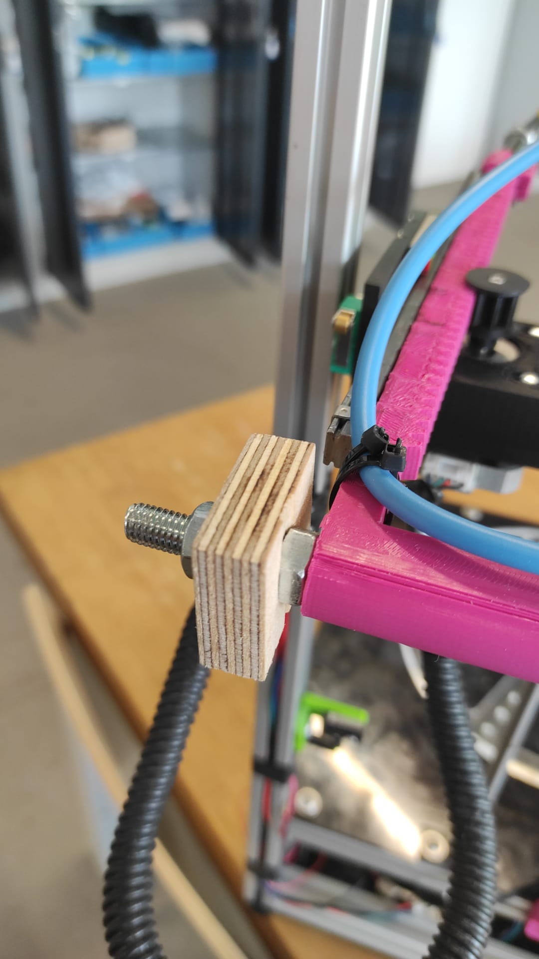
for the X-LimitSwich We just eyballed the position on the Z-Carriage. At the poínt it looked good and it would be triggered by the Rod with an the wooden extension, i marked the holes, and drilled them with a 2mm Drillbit Last Step was screwing the X-LimitSwich with two woodscrews into the drilled holes.
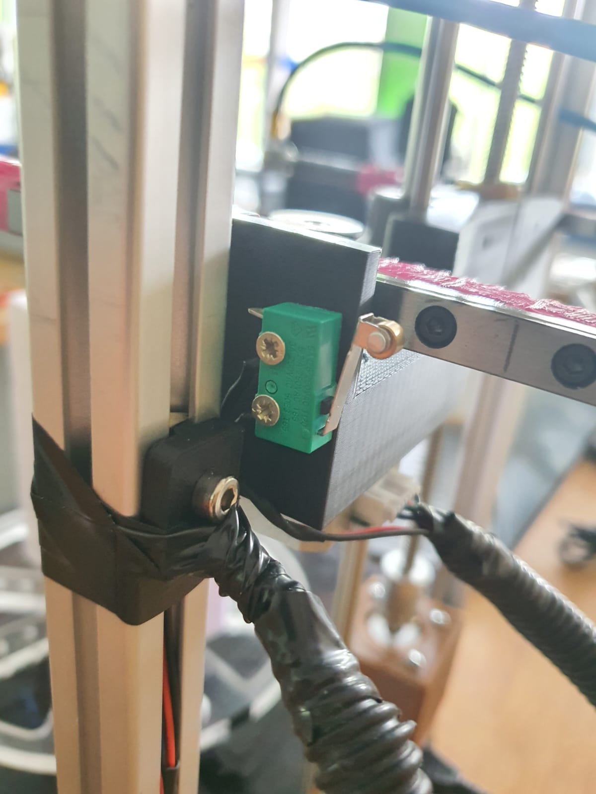
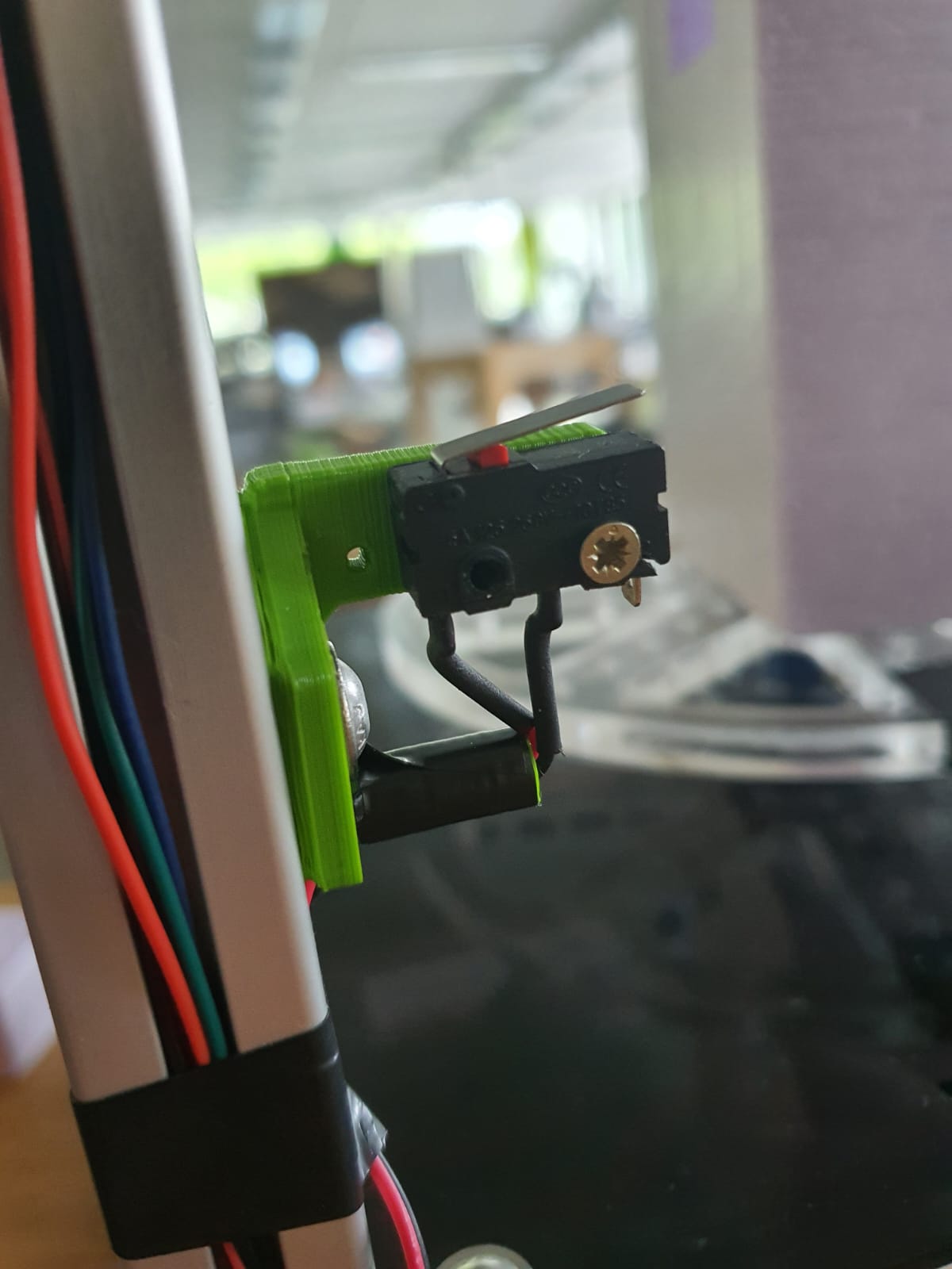
LimitZ
Leen edited my CableHolder(which you also need later and is not in the production files) as holder for the Z-Limit Switch. Which is placed on the inside and motor side of the frame, so that after screwing the LimitSwitch(which two wires on NO and G are soldered to) with one of the wood screws to the holder, is able to be pressed by the motor on the Z-Assembly. The heigth was adjusted by turning the Leadscrew until the Z-Carriage nearly hits flex-coupler. The Switch Holder was screwed at the point, where the limit Switch was pressed.
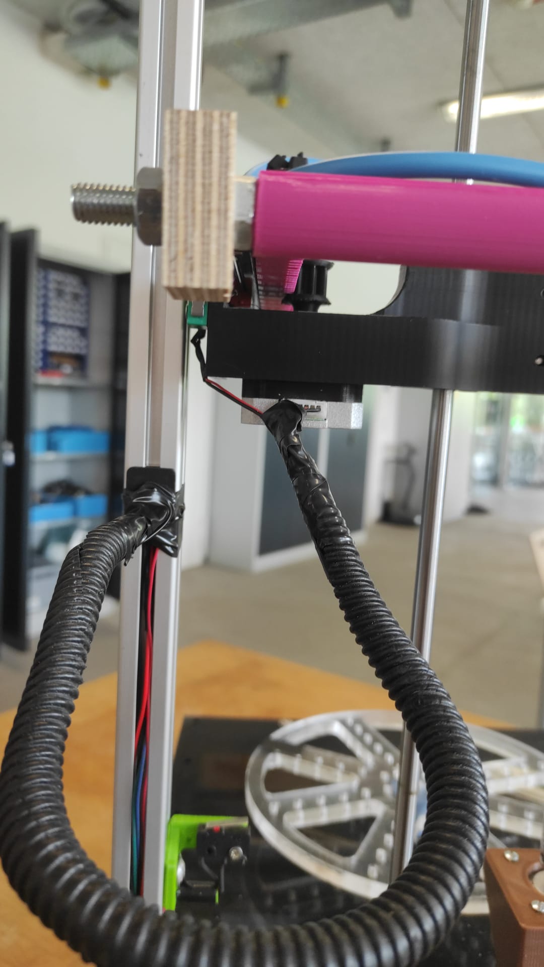
cablemanagement
This also was an easy Task. We mounted the cable holder in the middle of the travelway of the Z-Axis(with the m5 Screw) Then Routed the X-Limit and X-Motor Cables through a piece of Corrigated Tube with 15mm inner diameter for cablemanagement to the Cable Holder and secured everything on both sides with electrical Tape. the wires then were in the channel to hide and again used electrical tape for securing. We also routed the Cable from the Z-LimitSwitch through the caneel to the bottom compartment.
Wiring and Electronics
Electronics Datasheets
- Raspberry Pi Pico 2W
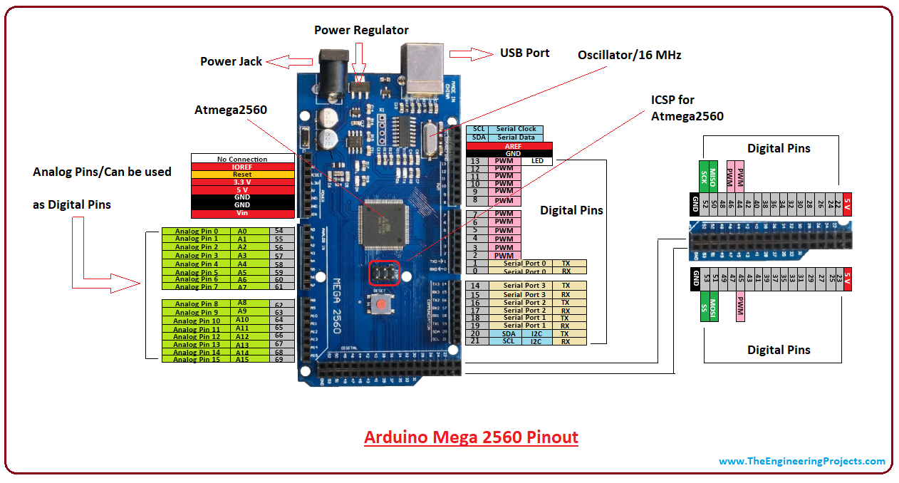
- Arduino Mega 2560
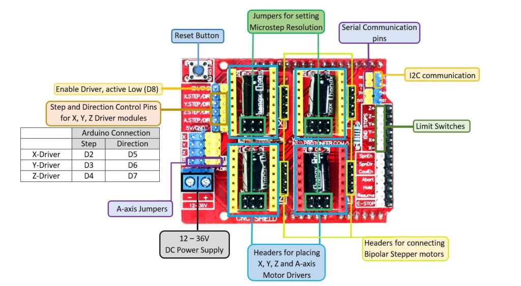
- CNC Shield
- A4988 Stepper Driver
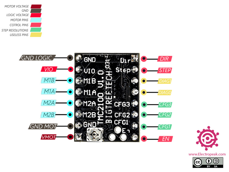
- TMC2100 Stepper Driver
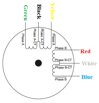
- NEMA17 Stepper Motor
- single core cable, PVC insulated
Electronics Pinouts


Electronics Used for Debugging
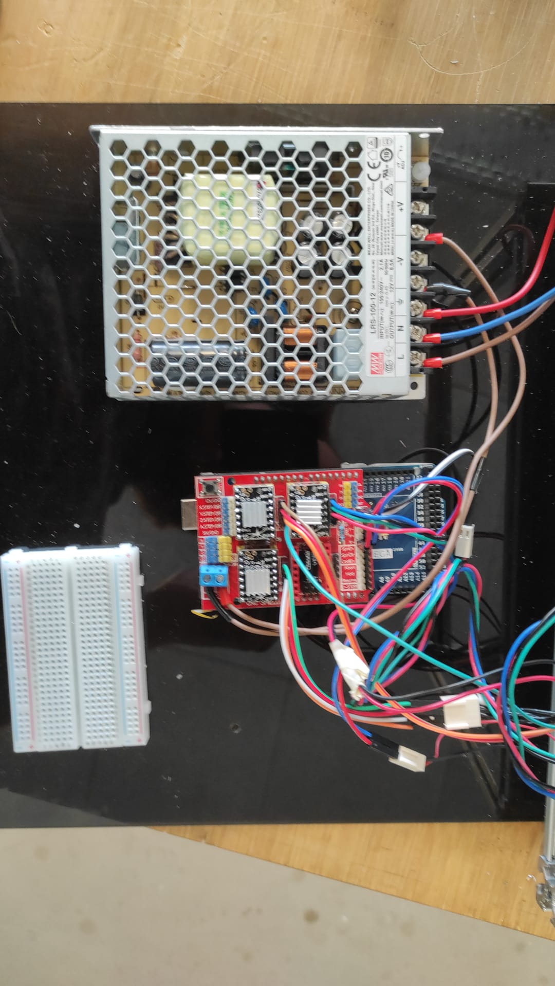
12V
For Connecting 12V we first placed the 12VPSU onto the BotCover and marked the two bottom Screw holes of
the
PSU, drilled them as 3mm holes and screwed the PSU onto the BotCover with the M3x8mm screws.
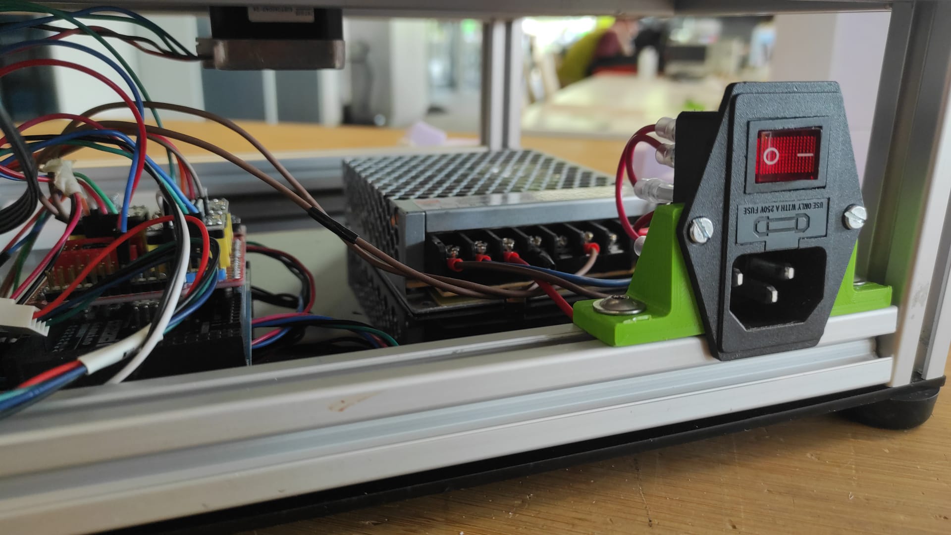
Now the IEC Powersocket. This was attached to the mounts with the M3x20mm and nuts, which then mounted
with
the M5 Screws to the Profile near the PSU.
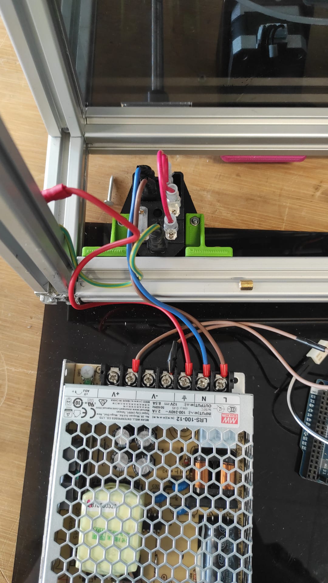
Both PSU and Powersocket in Place, we needed to start wiring. We crimped spade connectors to one side of
the
N and L cables and put them onto the 2 top connectors of the Switch from the Powersocket. a PE Cable was
also crimped on one side this way and put to the open Connector on the actual socket. The PE Cable got a
loop cable lug and was then connected with the red wire to the frame with the m4 screw and Slot nut. The
red
cable(used as PE) and the L and N cables where the attached to the corresponding terminals on the PSU.
On the 12V+ terminal We used a brown cable and on the 12V- terminal a black marked brown cable(we don't
had
cable in different color with same awg sufficient for the needed power on hand.)
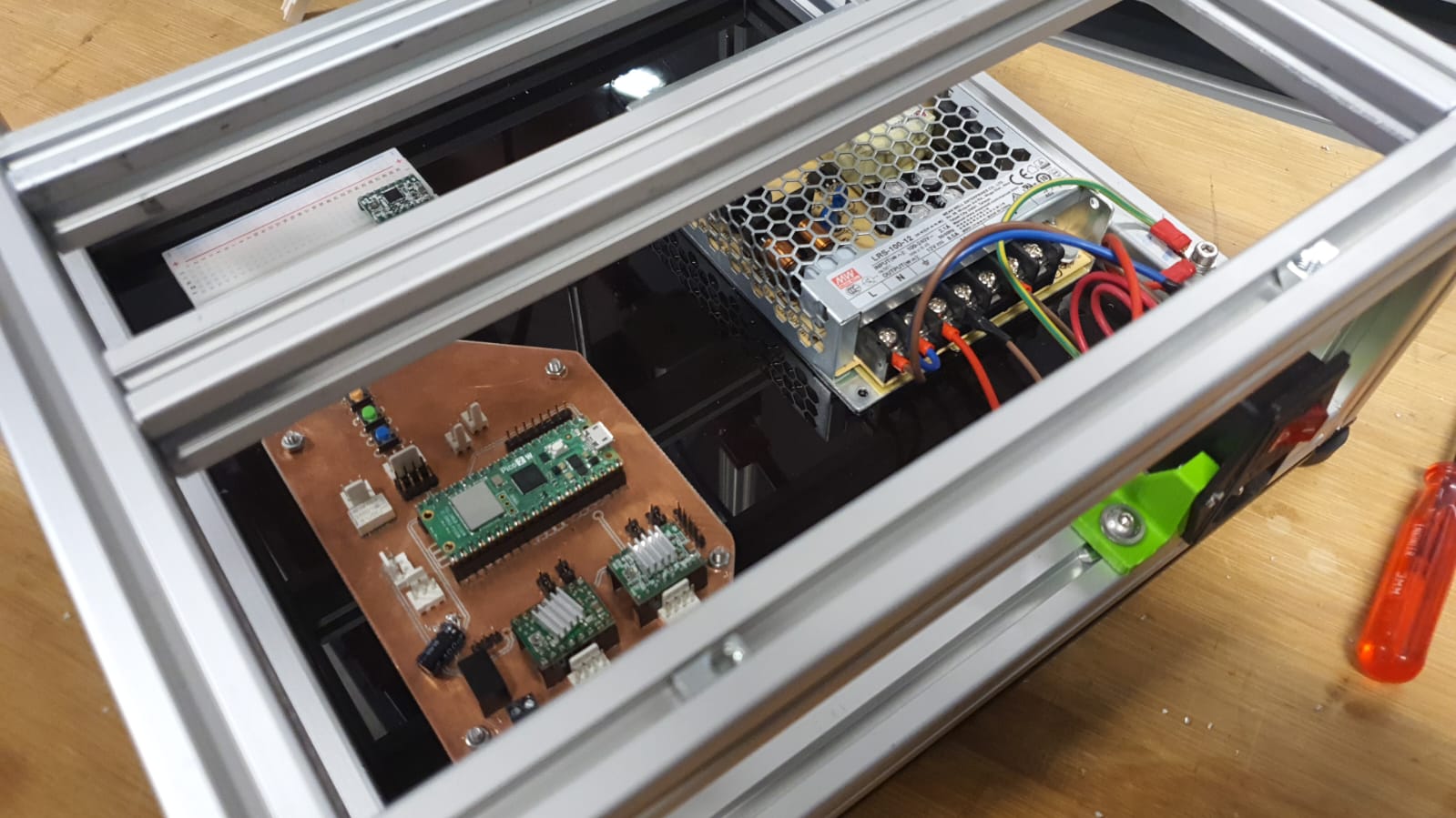
Using Mikas Board
First attempt was to use Mika's Board, because it had already 2 Slots for Stepper Drivers and also connection for 2 Limitswitches. After 2 hours of trying, we decided to switch to the CNC shield, which we already used for testing and setting the Current Limit of the Stepper Drivers for each Stepper, so we now it works.
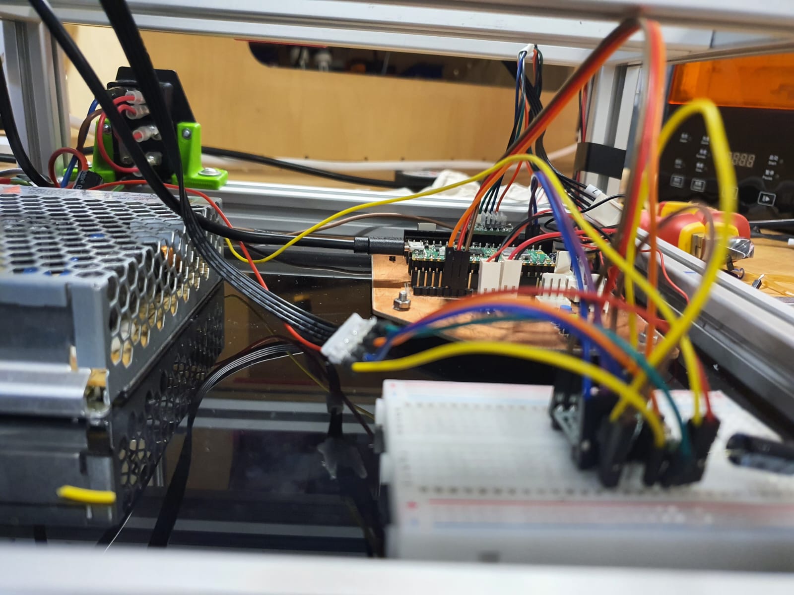
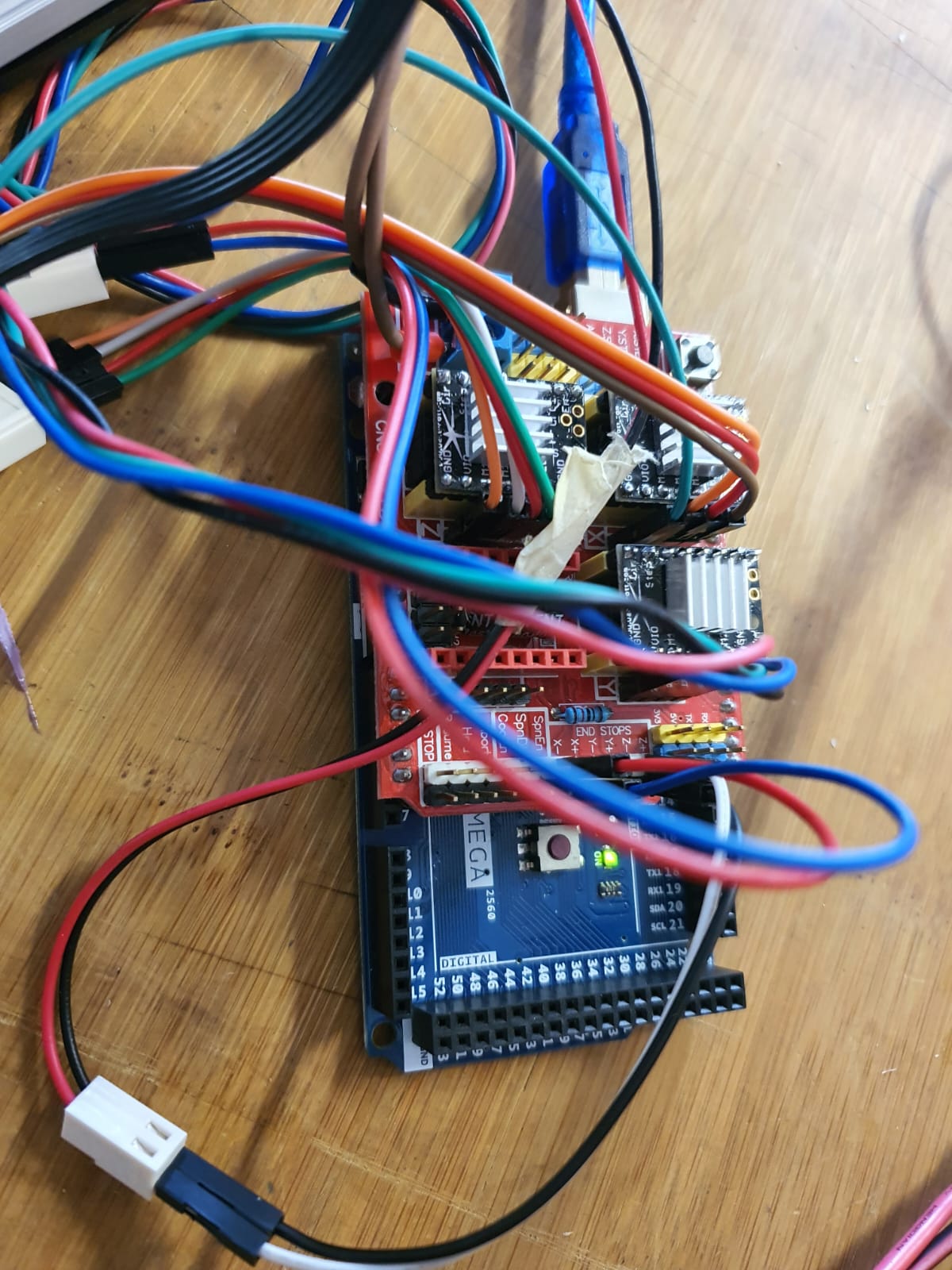
Using the CNC Shield
Connecting 12V to the CNCShield was done by connecting the brown and black mared Cable to the blue marked terminal. The TMC2100 drivers were put with the eneable pin to top left into X, Y and Z and the corresponding Motors rigth next to them. we also put Jumpers(marked green under the drivers) to set microstepping to 1/2. The Z and X LimitSwitches where connected to the corresponding + on black and white
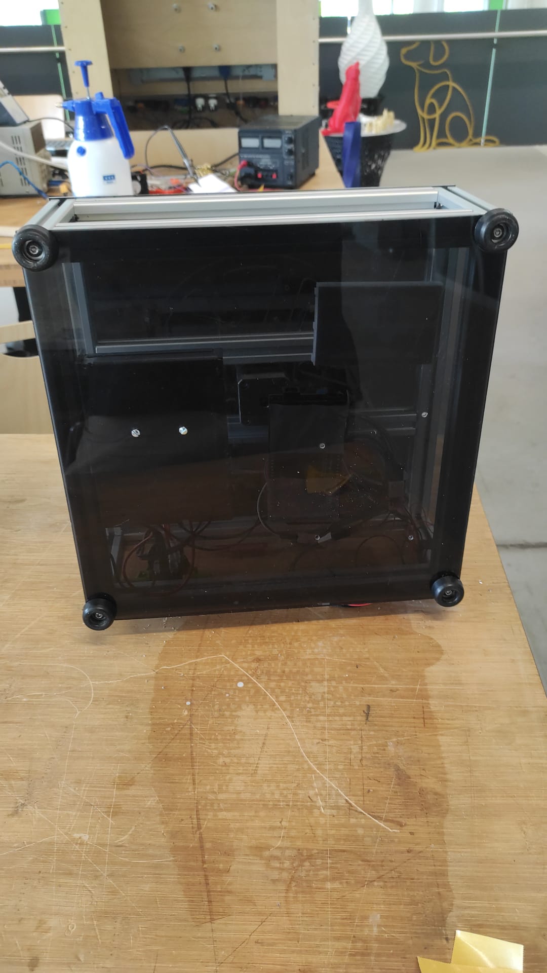
Cover It Up
Here we tapped the 4 corner profiles with m5 tread and screwed the BotCover with the Rubberfeet and 4 M5x10mm Screws to the Frame
lasercut Parts:
- 1x BotCover (4mm PlexiGlas)
- IEC power socket 2020 mount
other Parts:
- 1x Arduino Mega
- 1x CNC Shield
- 3x TMC2100 SilentStepStick Driver
- 1x IEC power socket
- 1x Meanwell 12V 8.5A Powersupply
- 2x M5 Slot5 SlotNuts
- 6x M5x10mm Socket Button Screws
- 2x M3x8mm Socket Cap Screws
- 2x M3x20mm Socket Cap Screws with nuts
- 4x Rubberfeet with 5mm hole
- 1x M4 Slot Nut
- 1x M4x8mm Socket Cap Screw
Manual Testing for Mechanical Movement
Coding and calculations
Stepper Motor Steps per mm Formulas
-
X‑axis (rack & pinion):
, where travel_per_rev_x is the distance the pinion-rack covers in one full motor revolution, measured manually or computed as π × pinion_diameter (see Linear Motion by Rack and Pinion and 4-Axis CNC Hot-wire Foam Cutter (Arduino+Ramps1.4)).steps_per_mm_x = (motor_steps_per_rev × microsteps) ÷ travel_per_rev_x -
Z‑axis (lead screw):
, where lead_screw_pitch is the linear distance (in mm) per one screw revolution. (see steps per mm for belt driven leadscrews)steps_per_mm_z = (motor_steps_per_rev × microsteps) ÷ lead_screw_pitch -
Y‑axis (rotational table):
steps_per_rev_y = motor_steps_per_rev × microsteps
, gives the exact number of step pulses to rotate the table by 1°.steps_per_degree_y = steps_per_rev_y ÷ 360
Manual Measurement for x-axis microsteps
Calculated Values (1/16 Microstepping)
-
X‑axis:
- motor_steps_per_rev = 200 full steps
- microsteps = 16 (1/16 mode → 200 × 16 = 3200 microsteps/rev)
- measured travel_per_rev_x = 39.5 mm/rev
-
steps_per_mm_x = 3200microsteps/rev ÷ 40mm/rev ≈ 80 microsteps/mm
-
Z‑axis:
- motor_steps_per_rev = 200 full steps
- microsteps = 16 (1/16 mode → 200 × 16 = 3200 microsteps/rev)
- lead_screw_pitch = 8 mm/rev
-
steps_per_mm_z = 3200microsteps/rev ÷ 8mm/rev = 400 microsteps/mm
-
Y‑axis:
- motor_steps_per_rev = 200 full steps
- microsteps = 16 (1/16 mode → 200 × 16 = 3200 microsteps/rev)
-
steps_per_degree_y = 3200microsteps/rev ÷ 360° ≈ 8.88 microsteps/° -
For a 90° face‑turn:
90° × 8.88microsteps/° ≈ 800 microsteps
Testing Stepper Motors and Debugging
Using ArduinoIDE Example
Stepper-One-Revolution Example Code
                            // Example sketch to control a stepper motor with A4988 stepper motor driver
// and Arduino without a library.
// More info: https://www.makerguides.com

// Define stepper motor connections and steps per revolution:
#define dirPin 16
#define stepPin 17
#define enPin 18

#define stepsPerRevolution 200

void setup() {
  // Declare pins as output:
  pinMode(stepPin, OUTPUT);
  pinMode(dirPin, OUTPUT);
  pinMode(enPin, OUTPUT);
  digitalWrite(enPin, LOW);


}

void loop() {
  // Set the spinning direction clockwise:
  digitalWrite(dirPin, HIGH);

  // Spin the stepper motor 1 revolution slowly:
  for (int i = 0; i < stepsPerRevolution; i++) {
    // These four lines result in 1 step:
    digitalWrite(stepPin, HIGH);
    delayMicroseconds(2000);
    digitalWrite(stepPin, LOW);
    delayMicroseconds(2000);
  }

  delay(1000);

  // Set the spinning direction counterclockwise:
  digitalWrite(dirPin, LOW);

  // Spin the stepper motor 1 revolution quickly:
  for (int i = 0; i < stepsPerRevolution; i++) {
    // These four lines result in 1 step:
    digitalWrite(stepPin, HIGH);
    delayMicroseconds(1000);
    digitalWrite(stepPin, LOW);
    delayMicroseconds(1000);
  }

  delay(1000);

  // Set the spinning direction clockwise:
  digitalWrite(dirPin, HIGH);

  // Spin the stepper motor 5 revolutions fast:
  for (int i = 0; i < 5 * stepsPerRevolution; i++) {
    // These four lines result in 1 step:
    digitalWrite(stepPin, HIGH);
    delayMicroseconds(500);
    digitalWrite(stepPin, LOW);
    delayMicroseconds(500);
  }

  delay(1000);

  // Set the spinning direction counterclockwise:
  digitalWrite(dirPin, LOW);

  //Spin the stepper motor 5 revolutions fast:
  for (int i = 0; i < 5 * stepsPerRevolution; i++) {
    // These four lines result in 1 step:
    digitalWrite(stepPin, HIGH);
    delayMicroseconds(500);
    digitalWrite(stepPin, LOW);
    delayMicroseconds(500);
  }

  delay(1000);
}
Test with Arduino Mega 2560 and CNC Shield

Test Code: Arduino Mega 2560 + CNC Shield
#define CW 0
#define CCW 1

const byte stepPin = 2; // x axis > 2, y axis > 3, z axis > 4 a axis > 12
const byte dirPin = 5; // x axis > 5, y axis > 6, z axis > 7 a axis > 13
const byte enablePin = 8;

unsigned long stepTime = 800;

void setup()
{
   Serial.begin(9600);
   pinMode(stepPin, OUTPUT);
   pinMode(dirPin, OUTPUT);
   pinMode(enablePin, OUTPUT);
   digitalWrite(enablePin, LOW);
   digitalWrite(dirPin, CCW);
}

void loop()
{
  oneStep();
}

void oneStep()
{
   static unsigned long timer = 0;
   unsigned long interval = stepTime;
   if (micros() - timer >= interval)
   {
      timer = micros();
      digitalWrite(stepPin, HIGH);
      delayMicroseconds(10);
      digitalWrite(stepPin, LOW);
   }
}
Programming our Pi Pico 2W in ArduinoIDE
-
Few Core Features of what the code does where set:
- Homing and Cut Task Buttons: Two buttons were selected so when pressed either homing or cutting starts (GPIO11 > Homing and GPIO12 > Cutting)
- Cutting Cube:Our goal was to cut eventually a 40mm ×40mm ×40mm cube out of our foam stock.
- X,Y, and Z Axes Pins Mapping: Pin mapping for Dir, Step, and En were left unchanged from Mika's schematic for X-axis motor (Width). However, Y-axis motor (rotational) pins was replaced with Z-axis motor (height) and for y-motor pins, we selected GPIO4 > Step, GPIO5 > Dir, and GPIO6 > En. This was fixed due to the positioning of the PCB and the extra breadboard on the base plate organizer in our LLM Foam Cutter, which were bound by the reach distance between each motor and its driver. Moreover, due to the thin cables we used and varying the current up to maximum while performing the initial testing for the z-axis, we fixated the pins accordingly.
Prompt
“I’m building a Pi Pico 2W–driven hot‑wire foam cutter that must carve out a 40 × 40 × 40 mm cube, no matter how large the starting block is. I want three cutting modes:-
For each of the three modes, produce a complete ArduinoIDE .ino sketches that:
- Use a constant const int cube_size_mm = 40; to define the cube edge length.
- Calculate steps_per_mm_x from 39.5 mm pinion‑rack travel distance → ≈ 41 microsteps/mm, and steps_per_mm_z from an 8 mm lead screw, all in 1/8 microstep mode (1600 microsteps/rev → 200 microsteps/mm).
- Compute rot90_steps = 1600 / 4 = 400 microsteps per 90°.
- Define all pins (X_STEP, X_DIR, ENX, LIMIT_X, etc.) exactly once.
- Include clean, concise comments on every #define, function and loop.
- Provide helper functions step(), moveX(), moveZ(), rotateY(), homeX(), homeZ().
- In setup(), only home X & Z via limit switches (no block‑height/width variables).
- Turn the hot‑wire “ON” at the start of each cut sequence and “OFF” at the end; optionally assume a bench supply handles the power so no power control via a pin is needed.
UPDATE!Drivers Not showing Response
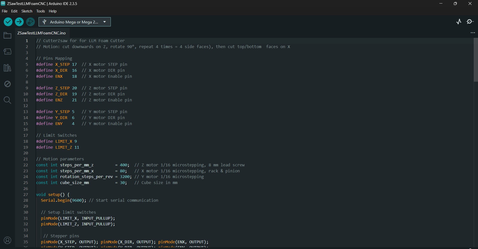
Test Code 1: Z‑Saw Cutter
// CutterZsaw for for LLM Foam Cutter
// Motion: cut downwards on Z, rotate 90°, repeat 4 times = 4 side faces, then cut top/bottom  faces on X


// Pins Mapping
#define X_STEP 17  // X motor STEP pin
#define X_DIR  16  // X motor DIR pin
#define ENX    18  // X motor Enable pin

#define Z_STEP 20  // Z motor STEP pin
#define Z_DIR  19  // Z motor DIR pin
#define ENZ    21  // Z motor Enable pin

#define Y_STEP 5   // Y motor STEP pin
#define Y_DIR  6   // Y motor DIR pin
#define ENY    4   // Y motor Enable pin

// Limit Switches
#define LIMIT_X 9
#define LIMIT_Z 11

// Motion parameters
const int steps_per_mm_z         = 400;  // Z motor 1/16 microstepping, 8 mm lead screw
const int steps_per_mm_x         = 80;   // X motor 1/16 microstepping, rack & pinion
const int rotation_steps_per_rev = 3200; // Y motor 1/16 microstepping
const int cube_size_mm           = 30;   // Cube size in mm

void setup() {
  Serial.begin(9600); // Start serial communication

  // Setup limit switches
  pinMode(LIMIT_X, INPUT_PULLUP);
  pinMode(LIMIT_Z, INPUT_PULLUP);

   // Stepper pins
  pinMode(X_STEP, OUTPUT); pinMode(X_DIR, OUTPUT); pinMode(ENX, OUTPUT);
  pinMode(Y_STEP, OUTPUT); pinMode(Y_DIR, OUTPUT); pinMode(ENY, OUTPUT);
  pinMode(Z_STEP, OUTPUT); pinMode(Z_DIR, OUTPUT); pinMode(ENZ, OUTPUT);

  // Enable motors
  digitalWrite(ENX, LOW);
  digitalWrite(ENY, LOW);
  digitalWrite(ENZ, LOW);

  Serial.println("Waiting 2 seconds before homing...");
  delay(2000);

  homeX();
  delay(5000);
  homeZ();
  delay(50);
  Serial.println("Waiting 2 seconds... Homing complete. Ready to cut!");
  delay(1000);

  // back off from switches
  Serial.println("Reference move: back off away from switches");
  moveZ(true, steps_per_mm_z * 65); //upwards
  delay(50);
  moveX(false, steps_per_mm_x * 123); //backwards
  delay(50);
  moveZ(false, steps_per_mm_z * 13); //downwards
  delay(2000);

  //to start the cut
  moveX(true, steps_per_mm_x * 15); //forwards

  runCubeCut();

  // done
  while (true) {}
}

void loop() {
  // Nothing!
}
// Homing functions
// Home Z‑axis by moving up until limit switch triggers

void homeZ() {
  Serial.print("Homing Z...");
  digitalWrite(Z_DIR, LOW);           // down
  while (digitalRead(LIMIT_Z) == HIGH) {
    step(Z_STEP);
    delayMicroseconds(200);
  }
  // bounce back 1 mm
  digitalWrite(Z_DIR, HIGH);          // up
  for (int i = 0; i < steps_per_mm_z; i++) {
    step(Z_STEP);
    delayMicroseconds(200);
  }
  Serial.println(" homed and bounced");
}

// Home X‑axis by moving backward until limit switch triggers
void homeX() {
  Serial.print("Homing X...");
  digitalWrite(X_DIR, HIGH);          // forward
  while (digitalRead(LIMIT_X) == HIGH) {
    step(X_STEP);
    delayMicroseconds(200);
  }
  // bounce back 1 mm
  digitalWrite(X_DIR, LOW);           // backward
  for (int i = 0; i < steps_per_mm_x; i++) {
    step(X_STEP);
    delayMicroseconds(200);
  }
  Serial.println(" X homed and bounced.");
}

void runCubeCut() {
    for (int face = 0; face < 4; face++) {
      // side cut
      moveZ(false,  steps_per_mm_z * cube_size_mm); //down
      delay(200);
      moveZ(true, steps_per_mm_z * cube_size_mm); //up
      delay(200);
      rotateY(true, rotation_steps_per_rev / 4); //rotate 90°
      delay(250);
    }

      // top/bottom cut
      moveZ(false,  steps_per_mm_z * cube_size_mm); //down
      delay(200);
      moveX(false, steps_per_mm_x * cube_size_mm); //backward
      delay(250);
      moveZ(true,  steps_per_mm_z * cube_size_mm*2); //up
      delay(200);

      Serial.println("Cube cut complete.");

  }

  // Rotate Y‑axis table CW or CCW
  void rotateY(bool clockwise, int steps) {
    digitalWrite(Y_DIR, clockwise ? HIGH : LOW);
    for (int i = 0; i < steps; i++) {
      step(Y_STEP);
      delayMicroseconds(200);
    }
  }

  // Move Z‑axis alone (down/up)
  void moveZ(bool down, int steps) {
    digitalWrite(Z_DIR, down ? HIGH : LOW);
    for (int i = 0; i < steps; i++) {
      step(Z_STEP);
      delayMicroseconds(200);
    }
  }

  // Move X‑axis alone (inward/outward)
  void moveX(bool inward, int steps) {
    digitalWrite(X_DIR, inward ? HIGH : LOW);
    for (int i = 0; i < steps; i++) {
      step(X_STEP);
      delayMicroseconds(200);
    }
  }

  // Generic step pulse generator
  void step(int pin) {
    digitalWrite(pin, HIGH);
    delayMicroseconds(60);
    digitalWrite(pin, LOW);
    delayMicroseconds(600);
  }
Pi Pico 2W Version: Test Code 2: Diagonal Cutter
// Pi Pico 2W Version: Diagonal Cube Cutter for LLM Foam Cutter
// Cuts four diagonal faces (Z+X sync), then top & bottom faces horizontally

// Pins Mapping
#define X_STEP   17  // X motor STEP pin
#define X_DIR    16  // X motor DIR pin
#define ENX      18  // X motor Enable pin

#define Z_STEP   20  // Z motor STEP pin
#define Z_DIR    19  // Z motor DIR pin
#define ENZ      21  // Z motor Enable pin

#define Y_STEP    5  // Y motor STEP pin
#define Y_DIR     6  // Y motor DIR pin
#define ENY       4  // Y motor Enable pin

// Limit Switches and Hot Wire Pin
#define LIMIT_X   9  // X-axis limit switch pin
#define LIMIT_Z   8  // Z-axis limit switch pin
#define HOTWIRE   7  // Hot wire MOSFET control pin

// Safety Buttons
#define BTN_HOME  11 // Button to home axes
#define BTN_CUT   12 // Button to start cube cutting

// Motion settings
const int steps_per_mm_z   = 200;         // Z: 1/8 microstepping → 1600/8 = 200 µsteps/mm
const int steps_per_mm_x   = 41;          // X: ≈1600 microsteps / 39.5 mm ≃ 40.5 steps/mm
const int rotation_steps_per_rev   = 200;       // Y: 90° rotation = 200 microsteps/rev
const int cube_size_mm     = 40;          // Cube side length in mm
const float inset_mm = cube_size_mm / 1.41421356f; // from Pythagorean theorem  → 40 mm / √2  ≃ 28.28 mm

void setup() {
  Serial.begin(9600);             // Start serial monitor

  // Limit switch inputs
  pinMode(LIMIT_X, INPUT_PULLUP);
  pinMode(LIMIT_Z, INPUT_PULLUP);

  // Motor driver outputs
  for (int p : {X_STEP, X_DIR, ENX,
                Y_STEP, Y_DIR, ENY,
                Z_STEP, Z_DIR, ENZ})
    pinMode(p, OUTPUT);

  // Hot‑wire control
  pinMode(HOTWIRE, OUTPUT);
  digitalWrite(HOTWIRE, LOW);       // Hot wire OFF initially

  // Safety buttons
  pinMode(BTN_HOME, INPUT);
  pinMode(BTN_CUT,  INPUT);

  // Enable all drivers
  digitalWrite(ENX, LOW);
  digitalWrite(ENY, LOW);
  digitalWrite(ENZ, LOW);

  Serial.println("Ready: BTN_HOME→home, BTN_CUT→cut cube.");
}

void loop() {
  // If Home button pressed, home X & Z:
  if (digitalRead(BTN_HOME) == LOW) {
    Serial.println("BTN_HOME pressed → homing axes");
    homeZ(); delay(300);
    homeX(); delay(300);
    Serial.println("Homing done");
    while(digitalRead(BTN_HOME)==LOW) delay(10); // simple debounce/wait release
  }

  // If Cut button pressed, perform the full diagonal cube cut:
  if (digitalRead(BTN_CUT) == LOW) {
     homeZ();
     homeX(); // ensure we start from zero position!
    Serial.println("BTN_CUT pressed → starting diagonal cube cut");
    digitalWrite(HOTWIRE, HIGH);     // Turn hot wire ON

   // Four bevel cuts, one per corner
    for (int i = 0; i < 4; i++) {
      diagonalCut(inset_mm);                   // true 45° over inset_mm
      delay(500);
      moveZ(false, int(steps_per_mm_z * inset_mm)); // lift back up
      delay(200);
      rotateY(true, rotation_steps_per_rev / 4);              // swing to next corner
      delay(800);
    }
    // Top face horizontally
     moveZ(false, int(steps_per_mm_z * cube_size_mm));  // Raise wire to top face
    delay(500);
    moveX(true, steps_per_mm_x * cube_size_mm);          // X forward top cut
    delay(800);

    // Bottom face horizontally
    moveZ(true, steps_per_mm_z * cube_size_mm);          // Z down full cube height
    delay(500);
    moveX(false, steps_per_mm_x * cube_size_mm);         // X back bottom cut
    delay(800);

    digitalWrite(HOTWIRE, LOW);    // Turn hot wire OFF
    Serial.println("Cube Cut Done. Halting.");
    while (1) delay(10);           // Stop further execution
  }
}

// True 45° inset bevel, Bresenham‑style
void diagonalCut(float mm) {
  int sx = int(mm * steps_per_mm_x + 0.5f);
  int sz = int(mm * steps_per_mm_z + 0.5f);
  int err = sx - sz;

  digitalWrite(X_DIR, HIGH);  // inward
  digitalWrite(Z_DIR, HIGH);  // downward

  while (sx > 0 || sz > 0) {
    int e2 = err * 2;
    if (e2 > -sz && sx > 0) {
      step(X_STEP);
      err -= sz;
      sx--;
    }
    if (e2 <  sx && sz > 0) {
      step(Z_STEP);
      err += sx;
      sz--;
    }
    delayMicroseconds(500);
  }
}

// Home Z‑axis by moving up until limit switch triggers
void homeZ() {
  digitalWrite(Z_DIR, LOW);          // Z upward
  while (digitalRead(LIMIT_Z) == HIGH) {
    step(Z_STEP);
    delayMicroseconds(700);
  }
  Serial.println("Z homed");
}

// Home X‑axis by moving backward until limit switch triggers
void homeX() {
  digitalWrite(X_DIR, LOW);          // X backward
  while (digitalRead(LIMIT_X) == HIGH) {
    step(X_STEP);
    delayMicroseconds(700);
  }
  Serial.println("X homed");
}

// Rotate Y‑axis table CW or CCW
void rotateY(bool clockwise, int steps) {
  digitalWrite(Y_DIR, clockwise ? HIGH : LOW);
  for (int i = 0; i < steps; i++) step(Y_STEP);
}

// Move Z‑axis alone (down/up)
void moveZ(bool down, int steps) {
  digitalWrite(Z_DIR, down ? HIGH : LOW);
  for (int i = 0; i < steps; i++) step(Z_STEP);
}

// Move X‑axis alone (inward/outward)
void moveX(bool inward, int steps) {
  digitalWrite(X_DIR, inward ? HIGH : LOW);
  for (int i = 0; i < steps; i++) step(X_STEP);
}

// Generic step pulse generator
void step(int pin) {
  digitalWrite(pin, HIGH);
  delayMicroseconds(500);
  digitalWrite(pin, LOW);
  delayMicroseconds(500);
}
Pi Pico 2W Test Code 3: Wave Cutter
// Pi Pico 2W Version: Wave Cut Mode for LLM Foam Cutter
// Z-axis performs wavy motion while descending
// X-axis nudges in and out for slight ripple along cut

// Pins Mapping
#define X_STEP   17  // X motor STEP pin
#define X_DIR    16  // X motor DIR pin
#define ENX      18  // X motor Enable pin

#define Z_STEP   20  // Z motor STEP pin
#define Z_DIR    19  // Z motor DIR pin
#define ENZ      21  // Z motor Enable pin

#define Y_STEP    5  // Y motor STEP pin
#define Y_DIR     6  // Y motor DIR pin
#define ENY       4  // Y motor Enable pin

// Limit Switches and Hot Wire Pin
#define LIMIT_X   9  // X-axis limit switch pin
#define LIMIT_Z   8  // Z-axis limit switch pin
#define HOTWIRE   7  // Hot wire MOSFET control pin

// Safety Buttons
#define BTN_HOME  11 // Button to home axes
#define BTN_CUT   12 // Button to start cube cutting

// Motion Parameters
const int steps_per_mm_z    = 200;  // Z: 1/8 microstepping → 1600/8 = 200 steps per mm
const int steps_per_mm_x    = 41;   // X: ≈1600 microsteps / 39.5 mm ≃ 40.5 steps/mm
const int rotation_steps_per_rev       = 200;// Y: 90° rotation = 200 microsteps/rev
const int nudge_mm = 1;
const int   nudge_steps = nudge_mm * steps_per_mm_x;
const int cube_size_mm      = 40;   // Cube side length in mm

void setup() {
  Serial.begin(9600);           // Start serial communication

  // Set pins for limit switches
  pinMode(LIMIT_X, INPUT_PULLUP);
  pinMode(LIMIT_Z, INPUT_PULLUP);

  // Set pins for motors
  pinMode(X_STEP, OUTPUT); pinMode(X_DIR, OUTPUT); pinMode(ENX, OUTPUT);
  pinMode(Y_STEP, OUTPUT); pinMode(Y_DIR, OUTPUT); pinMode(ENY, OUTPUT);
  pinMode(Z_STEP, OUTPUT); pinMode(Z_DIR, OUTPUT); pinMode(ENZ, OUTPUT);

  // Set hot wire output
  pinMode(HOTWIRE, OUTPUT); digitalWrite(HOTWIRE, LOW); // Start with hot wire OFF

  // Set safety buttons
  pinMode(BTN_HOME, INPUT);
  pinMode(BTN_CUT,  INPUT);

  // Enable all motor drivers
  digitalWrite(ENX, LOW);
  digitalWrite(ENY, LOW);
  digitalWrite(ENZ, LOW);

  // Initial homing at power‑up
  Serial.println("Initial homing...");
  homeZ(); delay(300);          // Home Z-axis
  homeX(); delay(300);          // Home X-axis
  Serial.println("Ready: BTN_HOME→home, BTN_CUT→wave cut.");
}

void loop() {
  // If Home button pressed, re‑home axes:
  if (digitalRead(BTN_HOME) == LOW) {
    Serial.println("BTN_HOME pressed → homing axes");
    homeZ(); delay(300);
    homeX(); delay(300);
    Serial.println("Homing done");
    while (digitalRead(BTN_HOME) == LOW) delay(10); // wait release
  }

  // If Cut button pressed, perform the wave‑cube cut:
  if (digitalRead(BTN_CUT) == LOW) {
    homeZ();
    homeX(); // ensure we start from zero position!
    Serial.println("BTN_CUT pressed → starting wave cube cut");
    digitalWrite(HOTWIRE, HIGH); // Turn hot wire ON

    // Four wavy side faces
    for (int face = 0; face < 4; face++) {
      waveCut(cube_size_mm);                         // Wave‑pattern descent
      delay(300);
      moveZ(false, steps_per_mm_z * cube_size_mm);   // Return Z to top
      delay(200);
      rotateY(true,  rotation_steps_per_rev / 4);                    // Rotate table 90°
      delay(400);
    }

    // Top face horizontal cut
    moveZ(false, steps_per_mm_z * cube_size_mm);     // Ensure Z at top surface
    moveX(true,  steps_per_mm_x * cube_size_mm);     // X forward across top
    delay(500);

    // Bottom face horizontal cut
    moveZ(true,  steps_per_mm_z * cube_size_mm);     // Lower Z full cube height
    delay(200);
    moveX(false, steps_per_mm_x * cube_size_mm);     // X backward across bottom
    delay(500);

    digitalWrite(HOTWIRE, LOW);   // Turn hot wire OFF
    Serial.println("Wave Cube Cut Done. Halting.");
    while (1) delay(10);          // Stop execution
  }
}

// Wave side‑face cut
void waveCut(int mm) {
  digitalWrite(Z_DIR, HIGH);                 // Z downward
  digitalWrite(X_DIR, HIGH);                 // X inward
  for (int row = 0; row < mm; row++) {
    // descend 1 mm
    for (int z = 0; z < steps_per_mm_z; z++) step(Z_STEP);
     // nudge X every 4 mm (forward on row % 4 == 0, back on row % 4 == 2):
    if (row % 4 == 0) {
      for (int i = 0; i < nudge_steps; i++) step(X_STEP);
    }
    else if (row % 4 == 2) {
      digitalWrite(X_DIR, LOW);
      for (int i = 0; i < nudge_steps; i++) step(X_STEP);
      digitalWrite(X_DIR, HIGH);
    }
  }
}

// Homing Z-axis by moving up until limit switch triggers
void homeZ() {
  digitalWrite(Z_DIR, LOW);                 // Z upward
  while (digitalRead(LIMIT_Z) == HIGH) {
    step(Z_STEP);
    delayMicroseconds(700);
  }
  Serial.println("Z homed");
}

// Homing X-axis by moving backward until limit switch triggers
void homeX() {
  digitalWrite(X_DIR, LOW);                 // X backward
  while (digitalRead(LIMIT_X) == HIGH) {
    step(X_STEP);
    delayMicroseconds(700);
  }
  Serial.println("X homed");
}

// Rotate table (Y-axis rotation) CW or CCW
void rotateY(bool cw, int steps) {
  digitalWrite(Y_DIR, cw ? HIGH : LOW);
  for (int i = 0; i < steps; i++) step(Y_STEP);
}

// Move Z-axis up/down by `steps` pulses
void moveZ(bool down, int steps) {
  digitalWrite(Z_DIR, down ? HIGH : LOW);
  for (int i = 0; i < steps; i++) step(Z_STEP);
}

// Move X-axis inward/outward by `steps` pulses
void moveX(bool inw, int steps) {
  digitalWrite(X_DIR, inw ? HIGH : LOW);
  for (int i = 0; i < steps; i++) step(X_STEP);
}

// Generic step pulse generator
void step(int pin) {
  digitalWrite(pin, HIGH);
  delayMicroseconds(500);
  digitalWrite(pin, LOW);
  delayMicroseconds(500);
}
Problems and future Improvments
- The Gantry has to much tollerences! --) We can exchange the Rods and LM8UU Bearings with a MGN9 or even MGN12 Rail system
- Too much Z-Heigth wasted --) Moving the Z-Motor downwards or even inside the electronics Compartment
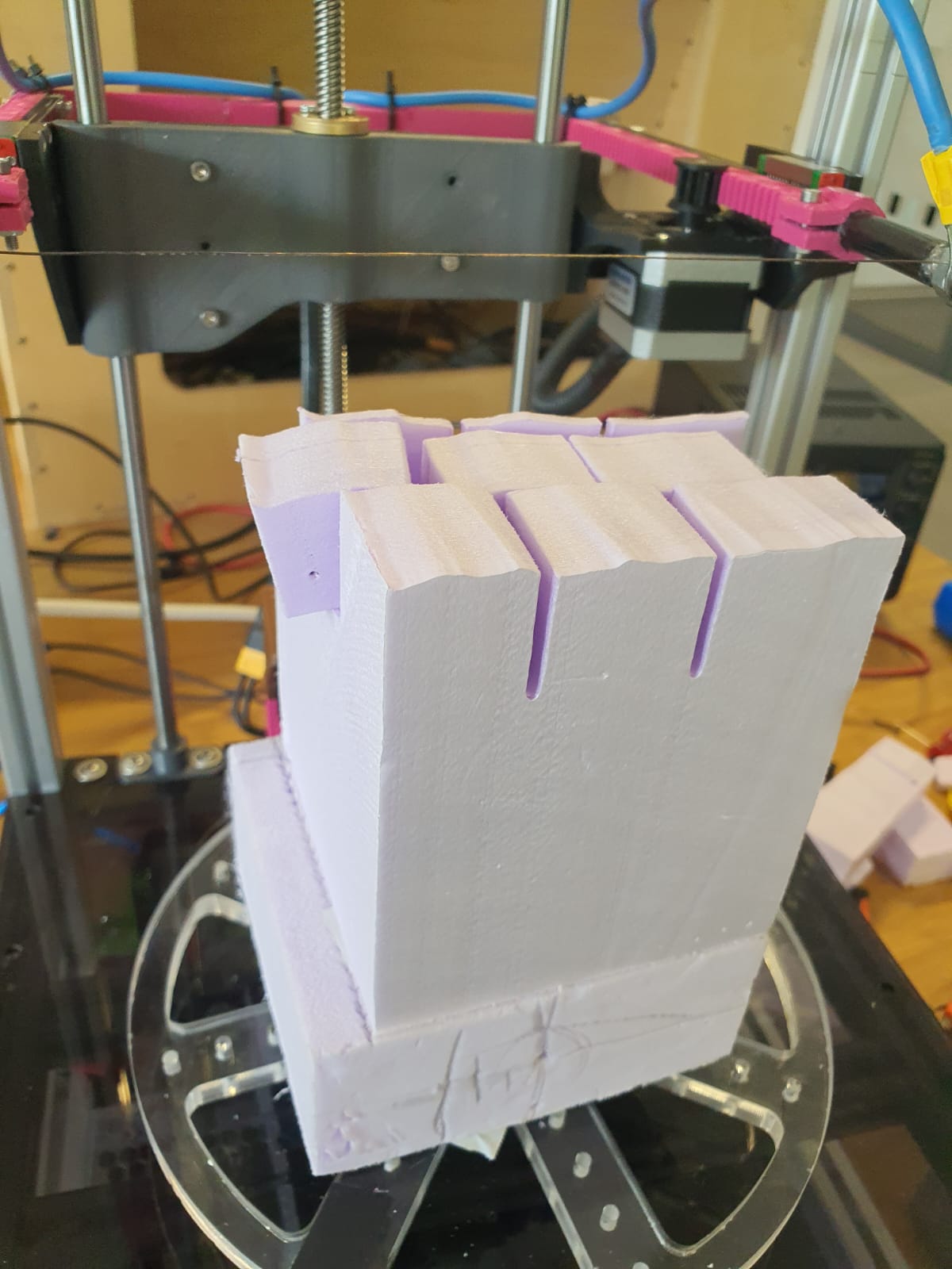
Reflection and Conclusion
The last two weeks felt like a non‑stop roller‑coaster. We fried drivers, mixed up limit‑switch pins, and even had a PCB that just refused to talk to our motors. Nevertheless, we managed to get back on track and continue working. Whenever something broke, one of us grabbed a multimeter or a screwdriver while someone else tweaked the code, and together we moved forward: from re‑wiring coils to swapping in the Arduino Mega + CNC shield. We managed a rough 40 × 40 × 40 mm cube, which proved the basic idea works, but the motions need smoothing and higher precision. The project is not flawless, but it is ready for further refinement after Fab Academy concludes. We've gained a lot of knowledge regarding documentation, rapid troubleshooting, and teamwork, all of which will help us in the future LLM Foam Cutter upgrades.
Resources
- Adrian_SAM. (2020). Re: CNC shield with A4988 and MEGA 2560 [Online forum post]. Arduino Forum. Retrieved from https://forum.arduino.cc/t/cnc-shield-with-a4988-and-mega-2560/665014/7
- Clever, D. (2020). Moving your CNC with Bresenham’s algorithm. Marginally Clever Robots. Retrieved from https://www.marginallyclever.com/2020/07/moving-your-cnc-with-bresenhams-algorithm/
- Collins, D. (n.d.). What is microstepping? Linear Motion Tips. Retrieved from https://www.linearmotiontips.com/microstepping-basics/
- De Barros, R. (n.d.). Control NEMA 17 with A4988: Arduino wiring & code guide. Retrieved from https://racheldebarros.com/arduino-projects/control-nema17-with-a4988-arduino-wiring-and-code-guide/
- dearhyunjoo. (n.d.). Linear motion by rack and pinion. Instructables. Retrieved from https://www.instructables.com/Linear-Motion-by-Rack-and-Pinion/
- Hermann, S. (n.d.). Arduino, A4988 Motortreiber und der Stepper‑Motor NEMA17. StartHardware.org. Retrieved from https://starthardware.org/arduino-a4988-nema17/
- Klipper Documentation. (n.d.). Rotation distance. Retrieved from https://www.klipper3d.org/Rotation_Distance.html
- k3nn7. (2023). How do you use limit switches with a CNC shield V3? (AccelStepper) [Online forum post]. Arduino Forum. Retrieved from https://forum.arduino.cc/t/how-do-you-use-limit-switches-with-a-cnc-shield-v3-accelstepper/1105316
- Last Minute Engineers. (n.d.). A4988 stepper motor driver with Arduino – tutorial. Retrieved from https://lastminuteengineers.com/a4988-stepper-motor-driver-arduino-tutorial/
- lucifer5. (2024). Operating Nema17 stepper motor at higher velocity with TMC2209 based on RP2040 Pi Pico [Online forum post]. Arduino Forum. Retrieved from https://forum.arduino.cc/t/operating-nema17-stepper-motor-at-higher-velocity-with-tmc2209-based-on-rp2040-pi-pico/1273070
- mech_n_wood. (2023). Arduino + CNC shield + A4988 + NEMA 17 [Online forum post]. Arduino Forum. Retrieved from https://forum.arduino.cc/t/arduino-cnc-shield-a4988-nema-17/1089060
- rahulsrajan. (n.d.). 4‑axis CNC hot‑wire foam cutter (Arduino + RAMPS 1.4). Instructables. Retrieved from https://www.instructables.com/4-Axis-CNC-Hot-wire-Foam-Cutter-ArduinoRamps14/
- RepRap Forum. (n.d.). Steps per mm for belt driven leadscrews [Online forum post]. Retrieved from https://reprap.org/forum/read.php?14,677333