Mechanical Design, Machine Design
Group Assignment
- Design a machine that includes mechanism+actuation+automation+application.
- Build the mechanical parts and operate it manually.
- actuate and automate your machine.
- Document the group project and your individual contribution.
Introduction
For this assignment, we were challenged to build a machine, and Lysander
immediately thought
of a hot wire foam cutting system. Our design features three stepper motors: one for
controlling the vertical (z-axis) movement, a second for adjusting the cutting depth of the
hot wire along the x-axis, and a third for rotating the base 360°, which holds the material.
This configuration allows for precise cuts and efficient foam shaping while maintaining
stability throughout the cutting process.
As for the name of our machine, we took our initials to represent the fact that it is our
combined efforts led to our great machine, the so called LLM Foam Cutter :P
LLM Foam Cutter's Roadmap
In order to have a clear vision of the necessary steps to complete our LLM Foam Cutter
Machine, we used Miro to have a proper overview of the tasks
sequence.
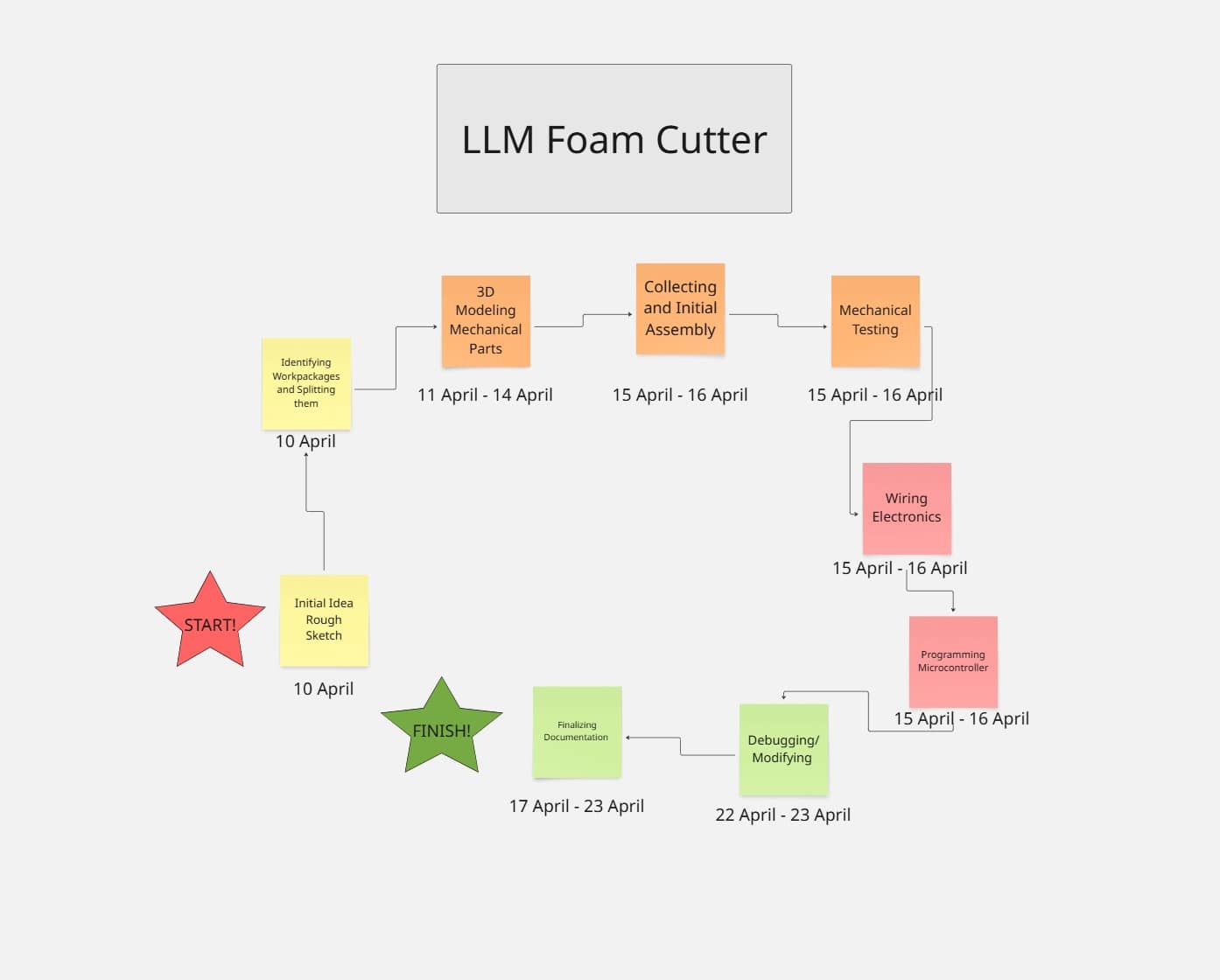
Work Packages Division
Work packages |
Responsibility |
|---|---|
| 3D Modeling | Mika + Lysander |
| Manufacturing | Mika + Lysander |
| Programming | Leen |
| Wiring | All |
| Assembly | All |
| Testing | All |
| Debugging/Improving | All |
| Project Management | Leen |
| Poster | Lysander |
| Video Edit/ Videography | Lysander |
| Documentation | All |
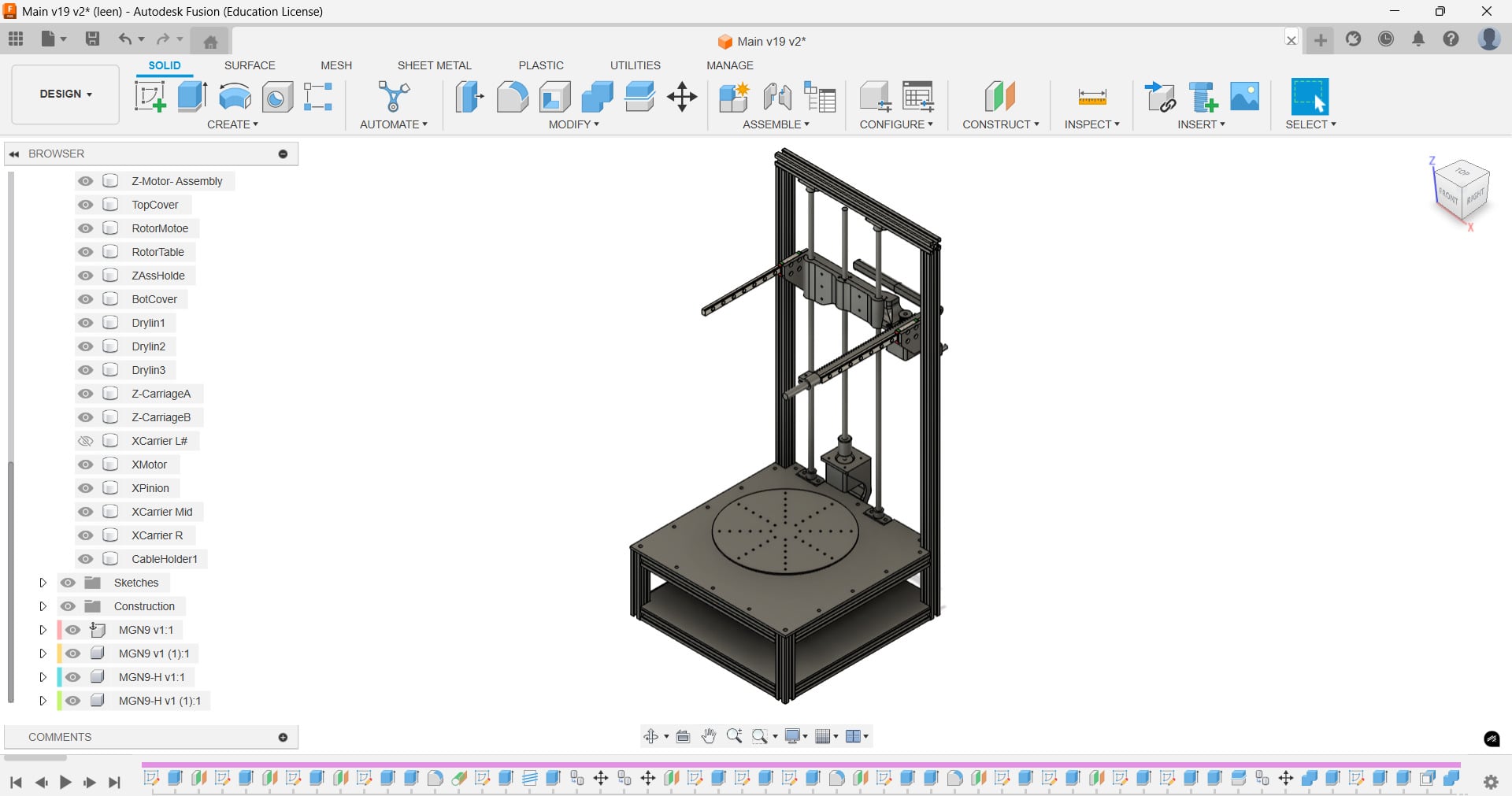
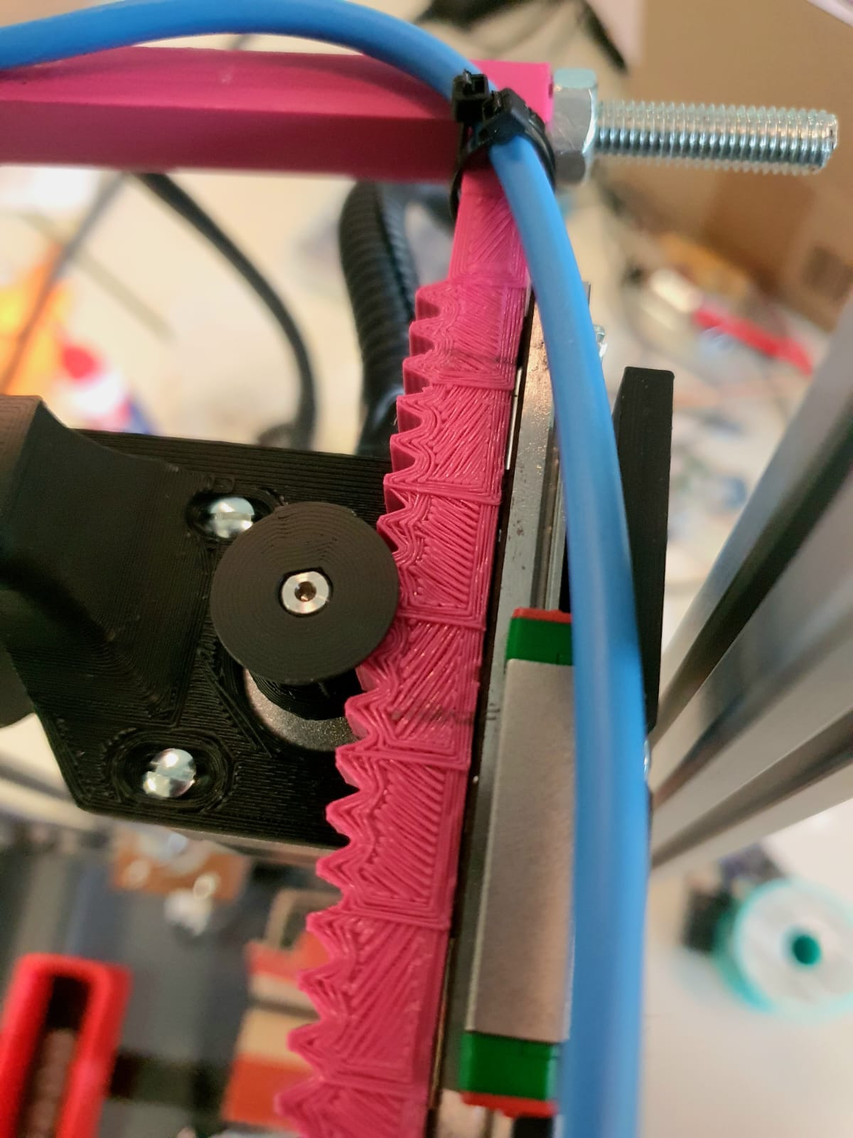
3D Modeling and Assembly in Fusion360
As stated in the workpackages table, Lysander
and Mika
are the ones responsible to design, manufacture, and put the frame and the mechanical parts
all together and I am there to assist them.
Please check out their pages for further details!
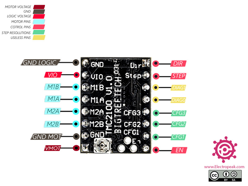
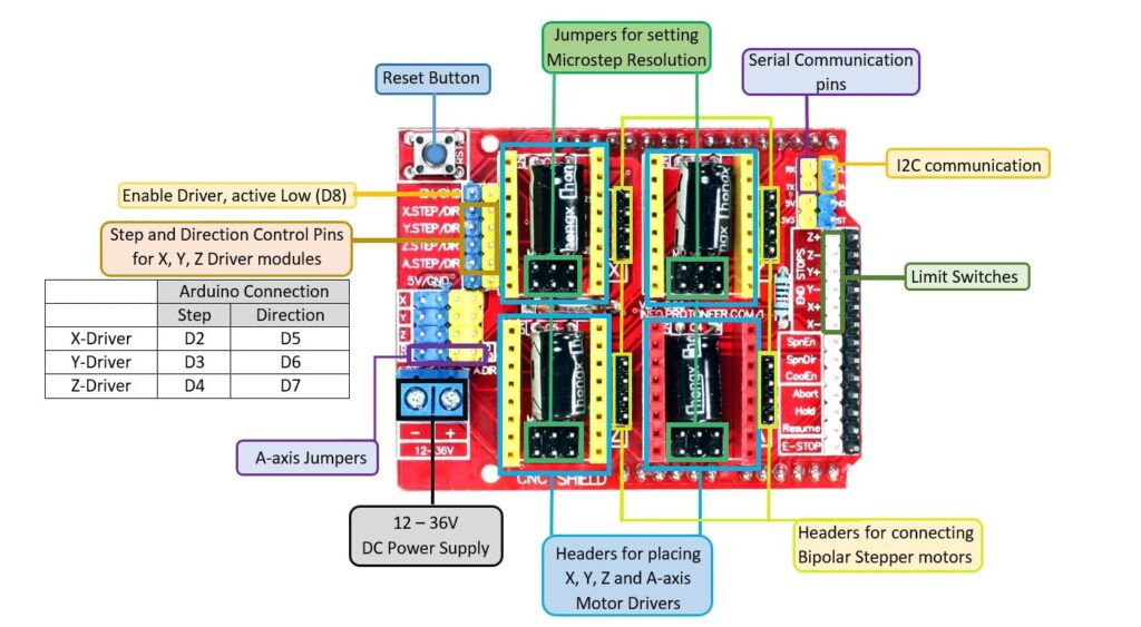
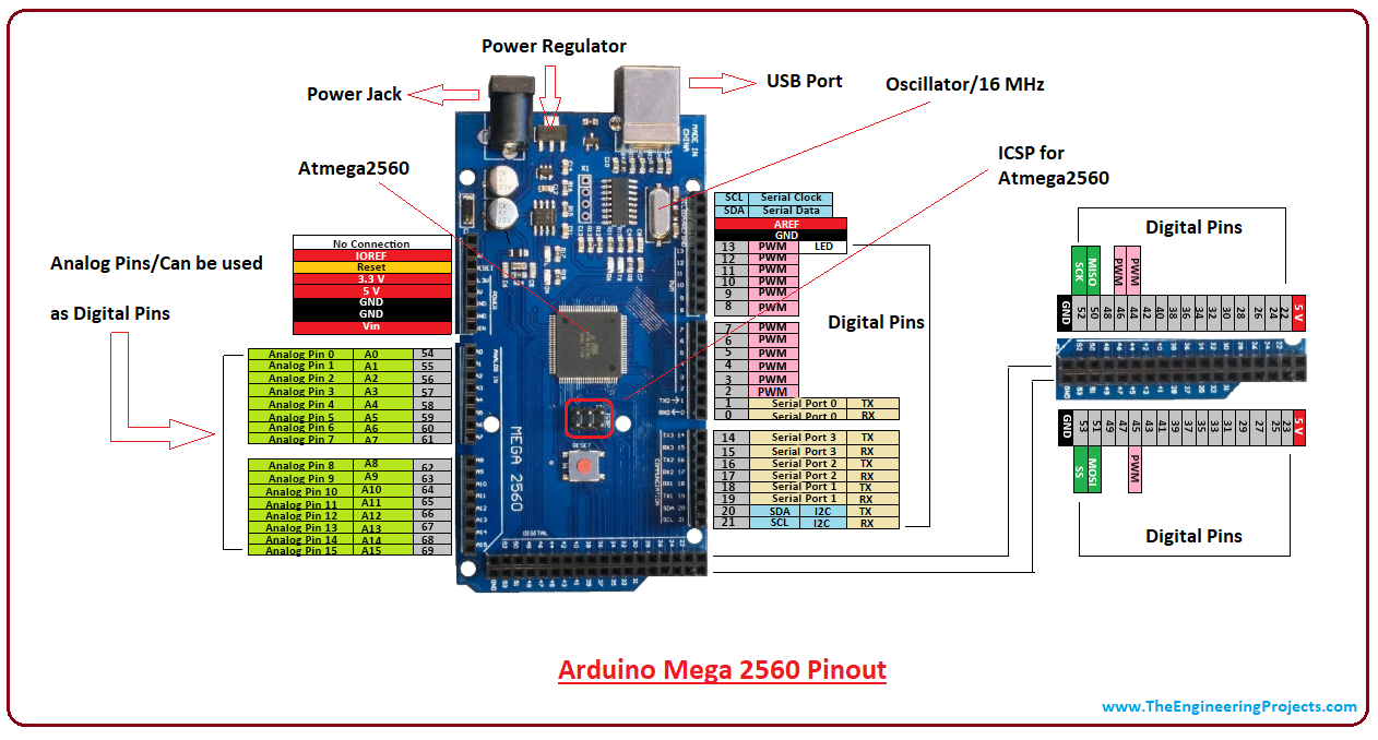
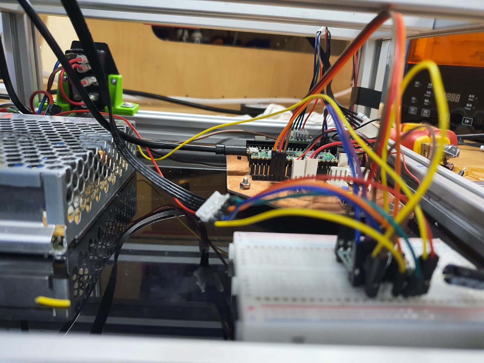
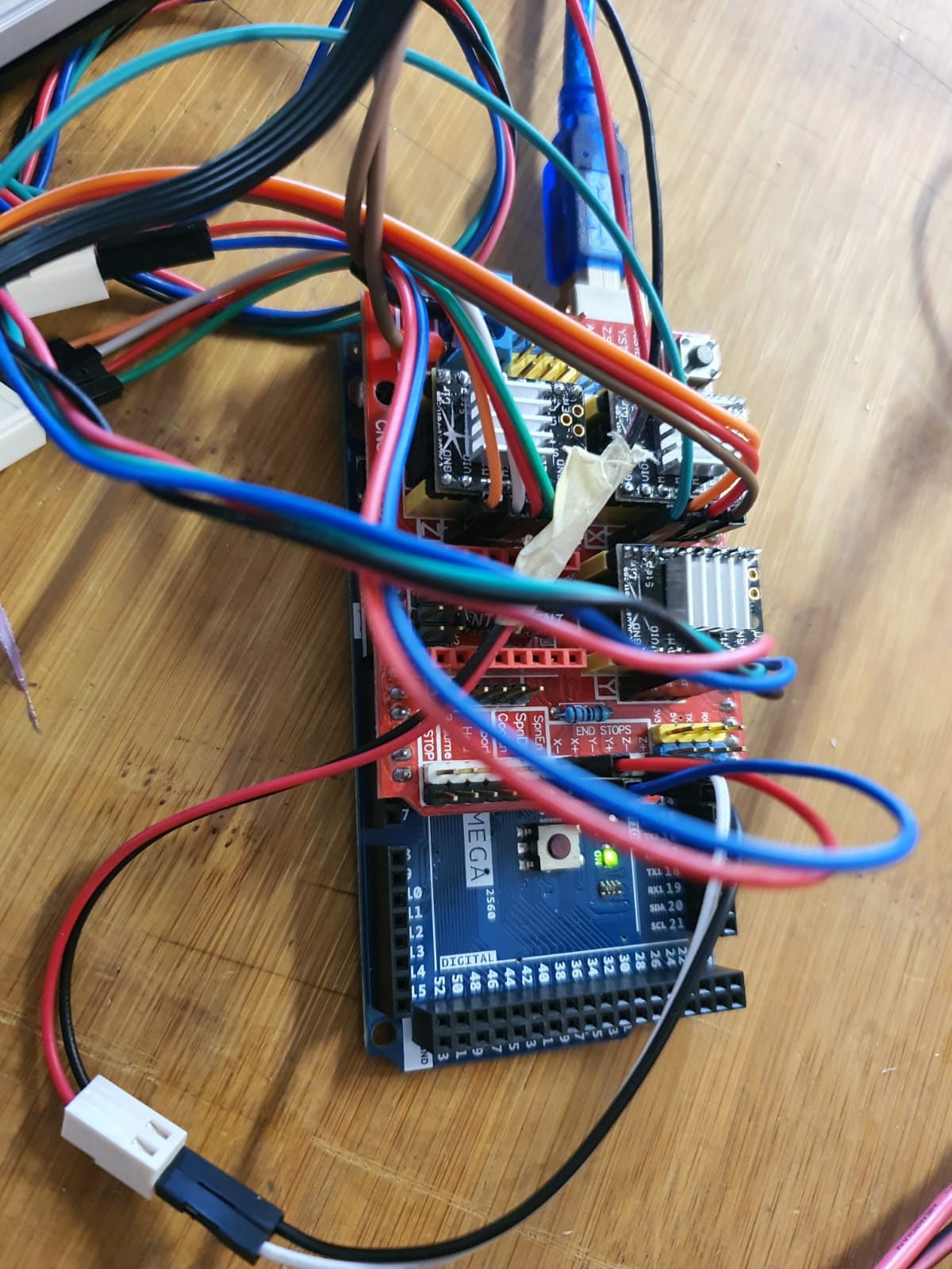
Electronics Datasheets
- Raspberry Pi Pico 2W
- Arduino Mega 2560
- CNC Shield
- A4988 Stepper Driver
- TMC2100 Stepper Driver
- NEMA17 Stepper Motor
- single core cable, PVC insulated
Electronics Pinouts


Electronics Used for Debugging
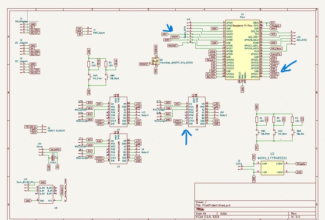
Schematic Overview
To try out hard coding a microcontroller other than Arduino Uno and the Grbl route, we
selected Mika's
PCB and modified it alittle bit. This is due to the fact that he already has two
dedicated stepper motor potions (EN, Dir, STEP) for x and y axes. I added a third symbol
to
represent the stepper motor and selected 3 pins from the Pi Pico 2 to control the steps
count, direction, and enable the driver and passes current through the motor.
Moreover, I added a mosfet to heat up the wire from our benchpower supply.
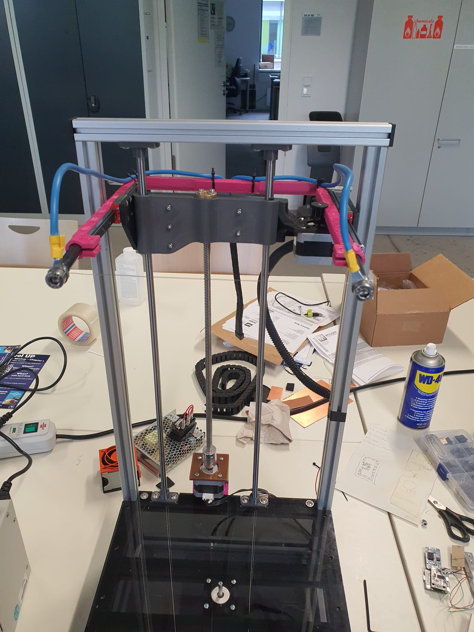
Manual Testing for Mechanical Movement
Lysander
and I used a bench power supply to manually test the hotwire configuration before
proceeding with automated cuts.
Our objective was to confirm that the hotwire heats up correctly and keeps the
temperature constant along its whole length.
We adjusted the voltage and current carefully to ensure the wire glowed slightly but did
not overheat or snap. We figured that the voltage of roughly 5V and the current of 0.4A
were suitable.
After confirming that the mechanical movement of the three axes and the ability of the
hot wire to cut the foam, we were ready to go for the automation step!
Stepper Motor Steps per mm Formulas
To get precise motion, we convert physical travel distance into steps
of the stepper motor:
For further information on microstepping calculations, check Klipper Documentation
and Linear Motion
Tips
-
X‑axis (rack & pinion):
, where travel_per_rev_x is the distance the pinion-rack covers in one full motor revolution, measured manually or computed as π × pinion_diameter (see Linear Motion by Rack and Pinion and 4-Axis CNC Hot-wire Foam Cutter (Arduino+Ramps1.4)).steps_per_mm_x = (motor_steps_per_rev × microsteps) ÷ travel_per_rev_x -
Z‑axis (lead screw):
, where lead_screw_pitch is the linear distance (in mm) per one screw revolution. (see steps per mm for belt driven leadscrews)steps_per_mm_z = (motor_steps_per_rev × microsteps) ÷ lead_screw_pitch -
Y‑axis (rotational table):
steps_per_rev_y = motor_steps_per_rev × microsteps
, gives the exact number of step pulses to rotate the table by 1°.steps_per_degree_y = steps_per_rev_y ÷ 360
Manual Measurement for x-axis microsteps
To find the rack’s travel per pinion revolution, we marked one tooth on both the pinion
and the rack.
Then we turned the pinion one revolution until the first rack mark again and measured
the distance between the rack’s first and second mark.
This distance is our travel_per_rev_x (in mm), which we plug into the
formula above.
Calculated Values (1/16 Microstepping)
-
X‑axis:
- motor_steps_per_rev = 200 full steps
- microsteps = 16 (1/16 mode → 200 × 16 = 3200 microsteps/rev)
- measured travel_per_rev_x = 39.5 mm/rev
-
steps_per_mm_x = 3200microsteps/rev ÷ 40mm/rev ≈ 80 microsteps/mm
-
Z‑axis:
- motor_steps_per_rev = 200 full steps
- microsteps = 16 (1/16 mode → 200 × 16 = 3200 microsteps/rev)
- lead_screw_pitch = 8 mm/rev
-
steps_per_mm_z = 3200microsteps/rev ÷ 8mm/rev = 400 microsteps/mm
-
Y‑axis:
- motor_steps_per_rev = 200 full steps
- microsteps = 16 (1/16 mode → 200 × 16 = 3200 microsteps/rev)
-
steps_per_degree_y = 3200microsteps/rev ÷ 360° ≈ 8.88 microsteps/° -
For a 90° face‑turn:
90° × 8.88microsteps/° ≈ 800 microsteps
Testing Stepper Motors and Debugging
Using ArduinoIDE Example
In order to check the integrity of the wiring that Mika
did most of, we went to examples, and in stepper, we
selected stepper-one-revolution and uploaded it on our pi pico, and we
exchanged the pins to match the correct mapping for testing X-axis motor.
However, the motor did not turn on at all. First, we thought it is a power issue; the
PCB did not receive any power. However, with a simple blink sketch we ejected that
hypothesis. Then, we went ahead and double checked all the wiring; whether the driver
and the motor are correctly connected to each other. Other theories were that our Nema17
motor(s) and/ or the A4988 driver(s) are faulty.
To confirm or reject those assumption, we decided to test them one by one with a simple
Arduino Mega 2560 + CNC shield.
Stepper-One-Revolution Example Code
                            // Example sketch to control a stepper motor with A4988 stepper motor driver
// and Arduino without a library.
// More info: https://www.makerguides.com

// Define stepper motor connections and steps per revolution:
#define dirPin 16
#define stepPin 17
#define enPin 18

#define stepsPerRevolution 200

void setup() {
  // Declare pins as output:
  pinMode(stepPin, OUTPUT);
  pinMode(dirPin, OUTPUT);
  pinMode(enPin, OUTPUT);
  digitalWrite(enPin, LOW);


}

void loop() {
  // Set the spinning direction clockwise:
  digitalWrite(dirPin, HIGH);

  // Spin the stepper motor 1 revolution slowly:
  for (int i = 0; i < stepsPerRevolution; i++) {
    // These four lines result in 1 step:
    digitalWrite(stepPin, HIGH);
    delayMicroseconds(2000);
    digitalWrite(stepPin, LOW);
    delayMicroseconds(2000);
  }

  delay(1000);

  // Set the spinning direction counterclockwise:
  digitalWrite(dirPin, LOW);

  // Spin the stepper motor 1 revolution quickly:
  for (int i = 0; i < stepsPerRevolution; i++) {
    // These four lines result in 1 step:
    digitalWrite(stepPin, HIGH);
    delayMicroseconds(1000);
    digitalWrite(stepPin, LOW);
    delayMicroseconds(1000);
  }

  delay(1000);

  // Set the spinning direction clockwise:
  digitalWrite(dirPin, HIGH);

  // Spin the stepper motor 5 revolutions fast:
  for (int i = 0; i < 5 * stepsPerRevolution; i++) {
    // These four lines result in 1 step:
    digitalWrite(stepPin, HIGH);
    delayMicroseconds(500);
    digitalWrite(stepPin, LOW);
    delayMicroseconds(500);
  }

  delay(1000);

  // Set the spinning direction counterclockwise:
  digitalWrite(dirPin, LOW);

  //Spin the stepper motor 5 revolutions fast:
  for (int i = 0; i < 5 * stepsPerRevolution; i++) {
    // These four lines result in 1 step:
    digitalWrite(stepPin, HIGH);
    delayMicroseconds(500);
    digitalWrite(stepPin, LOW);
    delayMicroseconds(500);
  }

  delay(1000);
}
Test with Arduino Mega 2560 and CNC Shield
For this test, we found a code for testing these exact motors (NEMA17) and drivers
(A4988) that we have. Mika started to plug one driver after the other, while testing
first the X-axis motor. The test was done by providing the power supply and then varying
the current via the potentiometer with the screwdriver to evaluate the impact on the
motors performance
(torque and speed) (check link).
We figured out that two out of the three drivers did not work and they needed
replacement. Moreover, the z-axis motor was also replaced, because
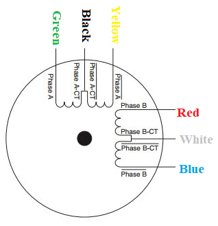
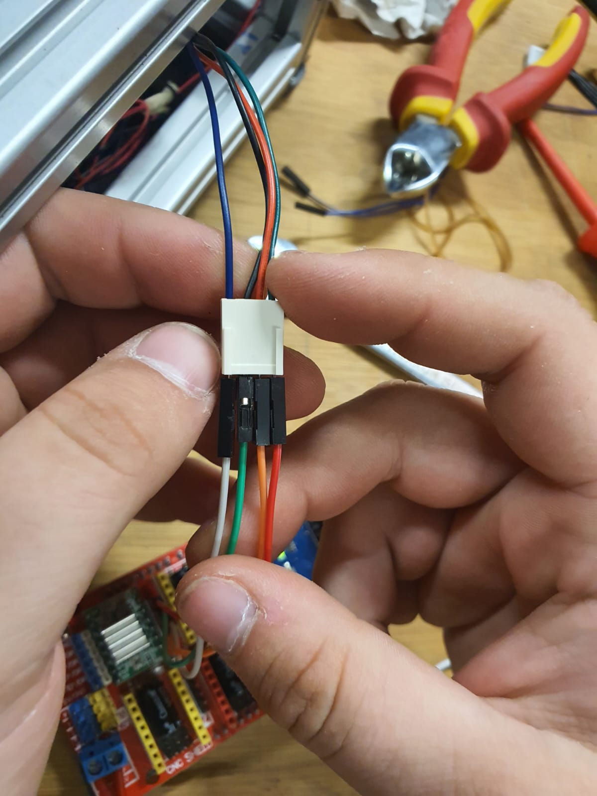
Additionally, confirming the correct coil pair configuration between the NEMA17 motor
(max → 12v, 2A)
and the A4988 driver was tricky, because the color code of the cables changes for each
supplier! Typically, A+ A– B+ B– of NEMA17 match to A4988’s 2B 2A 1A 1B (for further
information, please check Control
NEMA 17 with A4988: Arduino Wiring & Code Guide and Arduino, A4988 Motortreiber
und der Stepper-Motor NEMA17).
From our testing, we figured out that red and blue cables of NEMA17 are one phase → 1A
and 1B, and black and green cables of NEMA17 are one phase → 2A and 2B.
For further details on the testing and the wiring of the drivers and the motors, please
check Mika's
- Week 12 documentation!
Test Code: Arduino Mega 2560 + CNC Shield
#define CW 0
#define CCW 1

const byte stepPin = 2; // x axis > 2, y axis > 3, z axis > 4 a axis > 12
const byte dirPin = 5; // x axis > 5, y axis > 6, z axis > 7 a axis > 13
const byte enablePin = 8;

unsigned long stepTime = 800;

void setup()
{
   Serial.begin(9600);
   pinMode(stepPin, OUTPUT);
   pinMode(dirPin, OUTPUT);
   pinMode(enablePin, OUTPUT);
   digitalWrite(enablePin, LOW);
   digitalWrite(dirPin, CCW);
}

void loop()
{
  oneStep();
}

void oneStep()
{
   static unsigned long timer = 0;
   unsigned long interval = stepTime;
   if (micros() - timer >= interval)
   {
      timer = micros();
      digitalWrite(stepPin, HIGH);
      delayMicroseconds(10);
      digitalWrite(stepPin, LOW);
   }
}
Programming our Pi Pico 2W in ArduinoIDE
In order to save up time, given the limitation of Easter holidays, and since I
have not hardcoded any stepper motor to use, I used CharGPT as a starting point and I
tried to learn what the commands do in order to modify the base code that it provided me
with. Additionally, it was an experimentation for me to see how well I can write an
Arduino code with ChatGPT and how precise I can get with the prompt!
 For Nema17 motors calibration codes, you can find them at the end of this pages
under files!
For Nema17 motors calibration codes, you can find them at the end of this pages
under files!
 The following codes have not been tested yet. We will continue testing later on
when we have alittle more time on our hands to invest in LLM Foam Cutter!
The following codes have not been tested yet. We will continue testing later on
when we have alittle more time on our hands to invest in LLM Foam Cutter!
-
Few Core Features of what the code does where set:
- Homing and Cut Task Buttons: Two buttons were selected so when pressed either homing or cutting starts (GPIO11 > Homing and GPIO12 > Cutting)
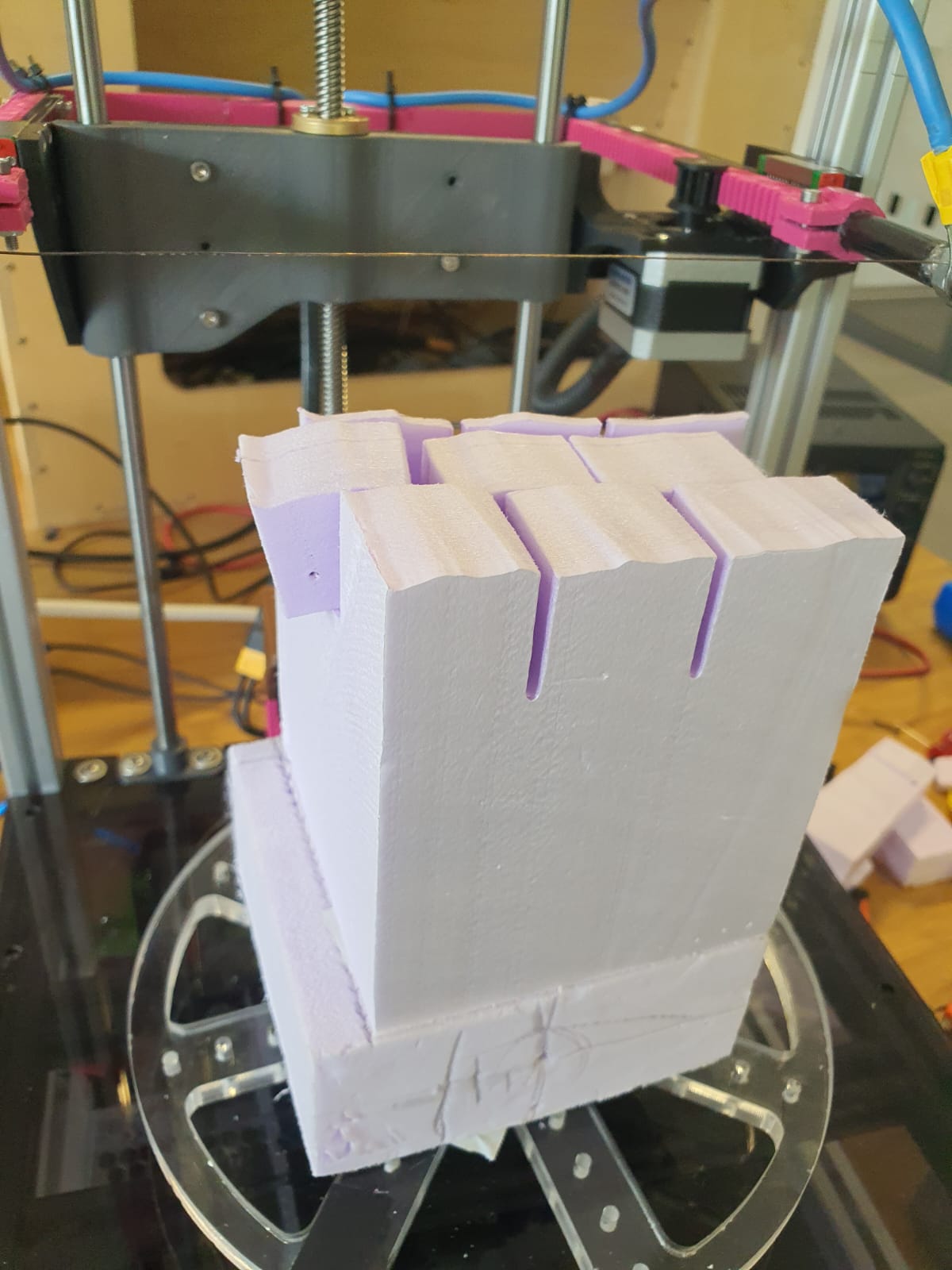
- Cutting Cube:Our goal was to cut eventually a 40mm ×40mm ×40mm cube out of our foam stock.
- X,Y, and Z Axes Pins Mapping: Pin mapping for Dir, Step, and En were left unchanged from Mika's schematic for X-axis motor (Width). However, Y-axis motor (rotational) pins was replaced with Z-axis motor (height) and for y-motor pins, we selected GPIO4 > Step, GPIO5 > Dir, and GPIO6 > En. This was fixed due to the positioning of the PCB and the extra breadboard on the base plate organizer in our LLM Foam Cutter, which were bound by the reach distance between each motor and its driver. Moreover, due to the thin cables we used and varying the current up to maximum while performing the initial testing for the z-axis, we fixated the pins accordingly.
Prompt
“I’m building a Pi Pico 2W–driven hot‑wire foam cutter that must carve out a
40 × 40 × 40 mm cube, no matter how large the starting block is. I want three cutting
modes:
ZSawCut: a pure Z‑“saw” up‑and‑down motion to slice the four vertical faces, then
one pass along X for the top face, a small Z lift, and a reverse X pass for the
bottom face.
DiagonalCut: synchronized Z+X motion to cut the four diagonal faces (applying
Bresenham's algorithm), then the same top‑and‑bottom X passes.
WaveCut: a wavy Z descent with X nudges every few millimeters for all four sides,
then the top‑and‑bottom X passes.
-
For each of the three modes, produce a complete ArduinoIDE .ino sketches that:
- Use a constant const int cube_size_mm = 40; to define the cube edge length.
- Calculate steps_per_mm_x from 39.5 mm pinion‑rack travel distance → ≈ 41 microsteps/mm, and steps_per_mm_z from an 8 mm lead screw, all in 1/8 microstep mode (1600 microsteps/rev → 200 microsteps/mm).
- Compute rot90_steps = 1600 / 4 = 400 microsteps per 90°.
- Define all pins (X_STEP, X_DIR, ENX, LIMIT_X, etc.) exactly once.
- Include clean, concise comments on every #define, function and loop.
- Provide helper functions step(), moveX(), moveZ(), rotateY(), homeX(), homeZ().
- In setup(), only home X & Z via limit switches (no block‑height/width variables).
- Turn the hot‑wire “ON” at the start of each cut sequence and “OFF” at the end; optionally assume a bench supply handles the power so no power control via a pin is needed.
UPDATE!Drivers Not showing Response
Our A4899 stepper drivers did not show any response. There was some communication
issues, which could be due to wrong wirng in the PCB. There is only two days left and we
had to keep going and find another solution. Therefore, we had to improvise and act
swiftly, and eventually
performed our automated test with the Arduino Mega 2560, the CNC
Shield, and 3 TMC2100
Stepper Drivers. We checked the datasheets of the CNC Shield and the TMC2100 and
we decided to go for 1/16 microstepping for all three axes. To map the pins and the
limit switches correctly we referred to multiple sources other than the datasheets like
Arduino
Forum - how do you use limit switches with a cnc shield and
Arduino Forum - cnc shield with a4988 and mega 2560. Our limit switches caused
us issues because intially we made a mistake with pulling the z limit switch was not
pulled down correctly; we had it on the -y of the CNC shield. Another
issue was with the mapping, we had the Z_Limit defined as 12 instead of
11.
Once these issues were solved, we managed to get the homing function running!
For more details on wiring, check Mika's
Documentation.
To calibrate the motion of each motor after wiring up the shield and the Arduino, we
used the example test from Arduino
Forum- step motor shifting/ microstepping example code and modified it.
From this test we confirmed that:
const int steps_per_mm_z = 400
const int steps_per_mm_x = 80
const int rotation_steps_per_rev = 3200
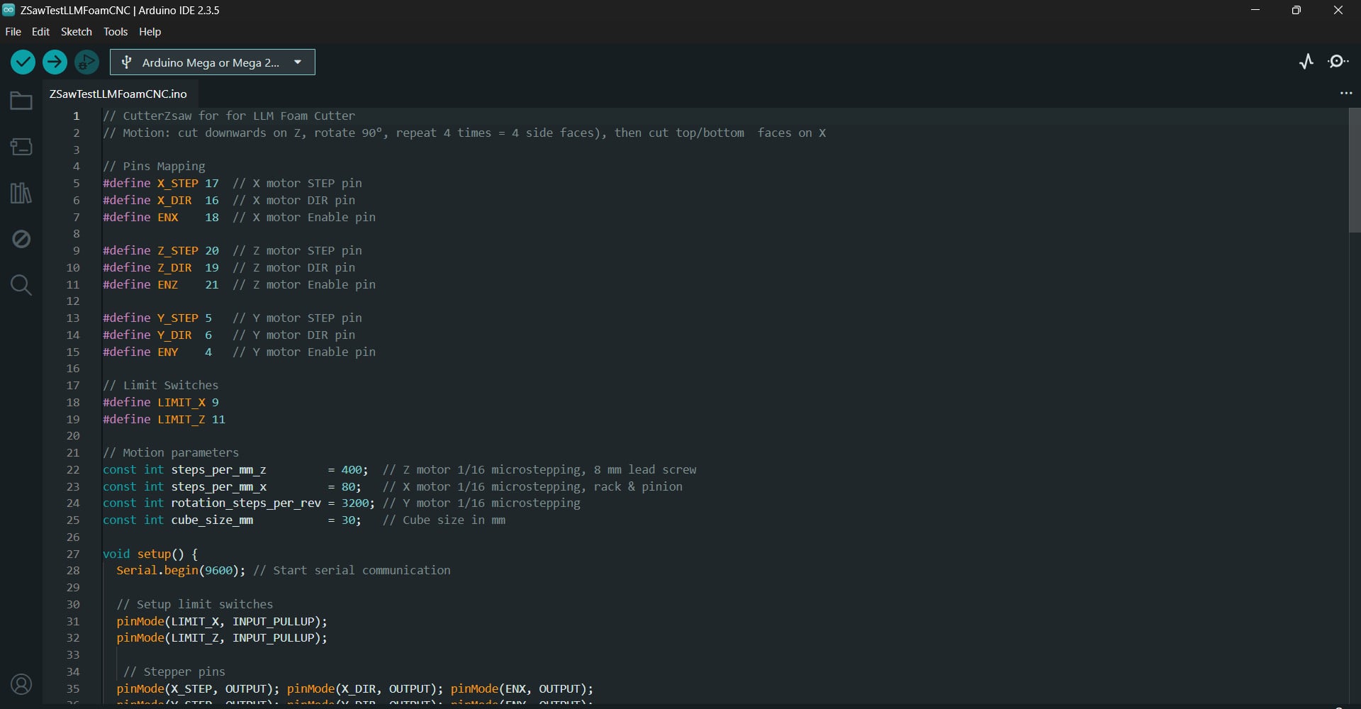
Test Code 1: Z‑Saw Cutter
In this sketch, the CNC foam cutter begins by homing the X and Z axes via their
pull‑up limit switches—each axis moves in until the switch closes, then bounces back
1 mm
Once homed, it backs the Z and X axes off the switches and moves them to the mid
point (considers our reference point). Afterwards, it positions
itself at the corner of the foam block.
Then, main cutting routine starts _RunCubeCut. Using 1/16
microstepping on the Z axis, it plunges downward 40 mm
(cube height), retracts the same amount, and repeats this cut four times, while
rotating the foam piece 90° on the Y axis (1/16 microstepping) between each pass
The cube is completed by plunging down the Z axis 40mm after the
side cuts are
finished, then making a final backwards (X-axis:1/16 microstepping) pass across the
top face and an upwards z motion with few millimeters extra above the foam block, to
demonstrate that the cutting job is done!
The end result was a 40mm ×40mm ×40mm cube!
// CutterZsaw for for LLM Foam Cutter
// Motion: cut downwards on Z, rotate 90°, repeat 4 times = 4 side faces, then cut top/bottom  faces on X


// Pins Mapping
#define X_STEP 17  // X motor STEP pin
#define X_DIR  16  // X motor DIR pin
#define ENX    18  // X motor Enable pin

#define Z_STEP 20  // Z motor STEP pin
#define Z_DIR  19  // Z motor DIR pin
#define ENZ    21  // Z motor Enable pin

#define Y_STEP 5   // Y motor STEP pin
#define Y_DIR  6   // Y motor DIR pin
#define ENY    4   // Y motor Enable pin

// Limit Switches
#define LIMIT_X 9
#define LIMIT_Z 11

// Motion parameters
const int steps_per_mm_z         = 400;  // Z motor 1/16 microstepping, 8 mm lead screw
const int steps_per_mm_x         = 80;   // X motor 1/16 microstepping, rack & pinion
const int rotation_steps_per_rev = 3200; // Y motor 1/16 microstepping
const int cube_size_mm           = 30;   // Cube size in mm

void setup() {
  Serial.begin(9600); // Start serial communication

  // Setup limit switches
  pinMode(LIMIT_X, INPUT_PULLUP);
  pinMode(LIMIT_Z, INPUT_PULLUP);

   // Stepper pins
  pinMode(X_STEP, OUTPUT); pinMode(X_DIR, OUTPUT); pinMode(ENX, OUTPUT);
  pinMode(Y_STEP, OUTPUT); pinMode(Y_DIR, OUTPUT); pinMode(ENY, OUTPUT);
  pinMode(Z_STEP, OUTPUT); pinMode(Z_DIR, OUTPUT); pinMode(ENZ, OUTPUT);

  // Enable motors
  digitalWrite(ENX, LOW);
  digitalWrite(ENY, LOW);
  digitalWrite(ENZ, LOW);

  Serial.println("Waiting 2 seconds before homing...");
  delay(2000);

  homeX();
  delay(5000);
  homeZ();
  delay(50);
  Serial.println("Waiting 2 seconds... Homing complete. Ready to cut!");
  delay(1000);

  // back off from switches
  Serial.println("Reference move: back off away from switches");
  moveZ(true, steps_per_mm_z * 65); //upwards
  delay(50);
  moveX(false, steps_per_mm_x * 123); //backwards
  delay(50);
  moveZ(false, steps_per_mm_z * 13); //downwards
  delay(2000);

  //to start the cut
  moveX(true, steps_per_mm_x * 15); //forwards

  runCubeCut();

  // done
  while (true) {}
}

void loop() {
  // Nothing!
}
// Homing functions
// Home Z‑axis by moving up until limit switch triggers

void homeZ() {
  Serial.print("Homing Z...");
  digitalWrite(Z_DIR, LOW);           // down
  while (digitalRead(LIMIT_Z) == HIGH) {
    step(Z_STEP);
    delayMicroseconds(200);
  }
  // bounce back 1 mm
  digitalWrite(Z_DIR, HIGH);          // up
  for (int i = 0; i < steps_per_mm_z; i++) {
    step(Z_STEP);
    delayMicroseconds(200);
  }
  Serial.println(" homed and bounced");
}

// Home X‑axis by moving backward until limit switch triggers
void homeX() {
  Serial.print("Homing X...");
  digitalWrite(X_DIR, HIGH);          // forward
  while (digitalRead(LIMIT_X) == HIGH) {
    step(X_STEP);
    delayMicroseconds(200);
  }
  // bounce back 1 mm
  digitalWrite(X_DIR, LOW);           // backward
  for (int i = 0; i < steps_per_mm_x; i++) {
    step(X_STEP);
    delayMicroseconds(200);
  }
  Serial.println(" X homed and bounced.");
}

void runCubeCut() {
    for (int face = 0; face < 4; face++) {
      // side cut
      moveZ(false,  steps_per_mm_z * cube_size_mm); //down
      delay(200);
      moveZ(true, steps_per_mm_z * cube_size_mm); //up
      delay(200);
      rotateY(true, rotation_steps_per_rev / 4); //rotate 90°
      delay(250);
    }

      // top/bottom cut
      moveZ(false,  steps_per_mm_z * cube_size_mm); //down
      delay(200);
      moveX(false, steps_per_mm_x * cube_size_mm); //backward
      delay(250);
      moveZ(true,  steps_per_mm_z * cube_size_mm*2); //up
      delay(200);

      Serial.println("Cube cut complete.");

  }

  // Rotate Y‑axis table CW or CCW
  void rotateY(bool clockwise, int steps) {
    digitalWrite(Y_DIR, clockwise ? HIGH : LOW);
    for (int i = 0; i < steps; i++) {
      step(Y_STEP);
      delayMicroseconds(200);
    }
  }

  // Move Z‑axis alone (down/up)
  void moveZ(bool down, int steps) {
    digitalWrite(Z_DIR, down ? HIGH : LOW);
    for (int i = 0; i < steps; i++) {
      step(Z_STEP);
      delayMicroseconds(200);
    }
  }

  // Move X‑axis alone (inward/outward)
  void moveX(bool inward, int steps) {
    digitalWrite(X_DIR, inward ? HIGH : LOW);
    for (int i = 0; i < steps; i++) {
      step(X_STEP);
      delayMicroseconds(200);
    }
  }

  // Generic step pulse generator
  void step(int pin) {
    digitalWrite(pin, HIGH);
    delayMicroseconds(60);
    digitalWrite(pin, LOW);
    delayMicroseconds(600);
  }
Pi Pico 2W Version: Test Code 2: Diagonal Cutter
In the following code, the CNC initiates the hot-wire after first homeing the X and
Z
axes using their limit switches.Using a Bresenham-style
synchronization, of X and Z steps, it performs an exact 45° bevel cut over
an
inset distance of 40/√2 mm for each of the four corners, guaranteeing a diagonal
plane
cutout.
The table is turned 90° (Y-axis) after each diagonal pass, and the procedure is
repeated
until all of the corners have been cut.
Afterwards, the cutter performs straight X-axis sweeps across the top and bottom
faces
to square off the ends. Lastly, the hotwire is turned off and the stepper drivers
are
disabled.
The end result will be a40mm ×40mm ×40mm cube with
chamfered sides!
// Pi Pico 2W Version: Diagonal Cube Cutter for LLM Foam Cutter
// Cuts four diagonal faces (Z+X sync), then top & bottom faces horizontally

// Pins Mapping
#define X_STEP   17  // X motor STEP pin
#define X_DIR    16  // X motor DIR pin
#define ENX      18  // X motor Enable pin

#define Z_STEP   20  // Z motor STEP pin
#define Z_DIR    19  // Z motor DIR pin
#define ENZ      21  // Z motor Enable pin

#define Y_STEP    5  // Y motor STEP pin
#define Y_DIR     6  // Y motor DIR pin
#define ENY       4  // Y motor Enable pin

// Limit Switches and Hot Wire Pin
#define LIMIT_X   9  // X-axis limit switch pin
#define LIMIT_Z   8  // Z-axis limit switch pin
#define HOTWIRE   7  // Hot wire MOSFET control pin

// Safety Buttons
#define BTN_HOME  11 // Button to home axes
#define BTN_CUT   12 // Button to start cube cutting

// Motion settings
const int steps_per_mm_z   = 200;         // Z: 1/8 microstepping → 1600/8 = 200 µsteps/mm
const int steps_per_mm_x   = 41;          // X: ≈1600 microsteps / 39.5 mm ≃ 40.5 steps/mm
const int rotation_steps_per_rev   = 200;       // Y: 90° rotation = 200 microsteps/rev
const int cube_size_mm     = 40;          // Cube side length in mm
const float inset_mm = cube_size_mm / 1.41421356f; // from Pythagorean theorem  → 40 mm / √2  ≃ 28.28 mm

void setup() {
  Serial.begin(9600);             // Start serial monitor

  // Limit switch inputs
  pinMode(LIMIT_X, INPUT_PULLUP);
  pinMode(LIMIT_Z, INPUT_PULLUP);

  // Motor driver outputs
  for (int p : {X_STEP, X_DIR, ENX,
                Y_STEP, Y_DIR, ENY,
                Z_STEP, Z_DIR, ENZ})
    pinMode(p, OUTPUT);

  // Hot‑wire control
  pinMode(HOTWIRE, OUTPUT);
  digitalWrite(HOTWIRE, LOW);       // Hot wire OFF initially

  // Safety buttons
  pinMode(BTN_HOME, INPUT);
  pinMode(BTN_CUT,  INPUT);

  // Enable all drivers
  digitalWrite(ENX, LOW);
  digitalWrite(ENY, LOW);
  digitalWrite(ENZ, LOW);

  Serial.println("Ready: BTN_HOME→home, BTN_CUT→cut cube.");
}

void loop() {
  // If Home button pressed, home X & Z:
  if (digitalRead(BTN_HOME) == LOW) {
    Serial.println("BTN_HOME pressed → homing axes");
    homeZ(); delay(300);
    homeX(); delay(300);
    Serial.println("Homing done");
    while(digitalRead(BTN_HOME)==LOW) delay(10); // simple debounce/wait release
  }

  // If Cut button pressed, perform the full diagonal cube cut:
  if (digitalRead(BTN_CUT) == LOW) {
     homeZ();
     homeX(); // ensure we start from zero position!
    Serial.println("BTN_CUT pressed → starting diagonal cube cut");
    digitalWrite(HOTWIRE, HIGH);     // Turn hot wire ON

   // Four bevel cuts, one per corner
    for (int i = 0; i < 4; i++) {
      diagonalCut(inset_mm);                   // true 45° over inset_mm
      delay(500);
      moveZ(false, int(steps_per_mm_z * inset_mm)); // lift back up
      delay(200);
      rotateY(true, rotation_steps_per_rev / 4);              // swing to next corner
      delay(800);
    }
    // Top face horizontally
     moveZ(false, int(steps_per_mm_z * cube_size_mm));  // Raise wire to top face
    delay(500);
    moveX(true, steps_per_mm_x * cube_size_mm);          // X forward top cut
    delay(800);

    // Bottom face horizontally
    moveZ(true, steps_per_mm_z * cube_size_mm);          // Z down full cube height
    delay(500);
    moveX(false, steps_per_mm_x * cube_size_mm);         // X back bottom cut
    delay(800);

    digitalWrite(HOTWIRE, LOW);    // Turn hot wire OFF
    Serial.println("Cube Cut Done. Halting.");
    while (1) delay(10);           // Stop further execution
  }
}

// True 45° inset bevel, Bresenham‑style
void diagonalCut(float mm) {
  int sx = int(mm * steps_per_mm_x + 0.5f);
  int sz = int(mm * steps_per_mm_z + 0.5f);
  int err = sx - sz;

  digitalWrite(X_DIR, HIGH);  // inward
  digitalWrite(Z_DIR, HIGH);  // downward

  while (sx > 0 || sz > 0) {
    int e2 = err * 2;
    if (e2 > -sz && sx > 0) {
      step(X_STEP);
      err -= sz;
      sx--;
    }
    if (e2 <  sx && sz > 0) {
      step(Z_STEP);
      err += sx;
      sz--;
    }
    delayMicroseconds(500);
  }
}

// Home Z‑axis by moving up until limit switch triggers
void homeZ() {
  digitalWrite(Z_DIR, LOW);          // Z upward
  while (digitalRead(LIMIT_Z) == HIGH) {
    step(Z_STEP);
    delayMicroseconds(700);
  }
  Serial.println("Z homed");
}

// Home X‑axis by moving backward until limit switch triggers
void homeX() {
  digitalWrite(X_DIR, LOW);          // X backward
  while (digitalRead(LIMIT_X) == HIGH) {
    step(X_STEP);
    delayMicroseconds(700);
  }
  Serial.println("X homed");
}

// Rotate Y‑axis table CW or CCW
void rotateY(bool clockwise, int steps) {
  digitalWrite(Y_DIR, clockwise ? HIGH : LOW);
  for (int i = 0; i < steps; i++) step(Y_STEP);
}

// Move Z‑axis alone (down/up)
void moveZ(bool down, int steps) {
  digitalWrite(Z_DIR, down ? HIGH : LOW);
  for (int i = 0; i < steps; i++) step(Z_STEP);
}

// Move X‑axis alone (inward/outward)
void moveX(bool inward, int steps) {
  digitalWrite(X_DIR, inward ? HIGH : LOW);
  for (int i = 0; i < steps; i++) step(X_STEP);
}

// Generic step pulse generator
void step(int pin) {
  digitalWrite(pin, HIGH);
  delayMicroseconds(500);
  digitalWrite(pin, LOW);
  delayMicroseconds(500);
}
Pi Pico 2W Test Code 3: Wave Cutter
In the following code, the hot-wire is turned on after the CNC homes the X and Z
axes at
the start (and prior to each cut).
It creates a wavy contour by nudging the X axis forward or backward by a specified
number of steps after every 4 mm of Z-axis travel.
This process carves each of the fckour sides in 1 mm increments. Z-axis rises back
to
the top between each side, and the table is turned 90°.
Afterwards, the cutter completes the cube by making straight X-axis passes across
the
top and bottom faces. Lastly, the hotwire is turned off and the stepper drivers are
disabled.
The end result will be a 40mm ×40mm ×40mm cube, but
each
side face will have a wave pattern!
// Pi Pico 2W Version: Wave Cut Mode for LLM Foam Cutter
// Z-axis performs wavy motion while descending
// X-axis nudges in and out for slight ripple along cut

// Pins Mapping
#define X_STEP   17  // X motor STEP pin
#define X_DIR    16  // X motor DIR pin
#define ENX      18  // X motor Enable pin

#define Z_STEP   20  // Z motor STEP pin
#define Z_DIR    19  // Z motor DIR pin
#define ENZ      21  // Z motor Enable pin

#define Y_STEP    5  // Y motor STEP pin
#define Y_DIR     6  // Y motor DIR pin
#define ENY       4  // Y motor Enable pin

// Limit Switches and Hot Wire Pin
#define LIMIT_X   9  // X-axis limit switch pin
#define LIMIT_Z   8  // Z-axis limit switch pin
#define HOTWIRE   7  // Hot wire MOSFET control pin

// Safety Buttons
#define BTN_HOME  11 // Button to home axes
#define BTN_CUT   12 // Button to start cube cutting

// Motion Parameters
const int steps_per_mm_z    = 200;  // Z: 1/8 microstepping → 1600/8 = 200 steps per mm
const int steps_per_mm_x    = 41;   // X: ≈1600 microsteps / 39.5 mm ≃ 40.5 steps/mm
const int rotation_steps_per_rev       = 200;// Y: 90° rotation = 200 microsteps/rev
const int nudge_mm = 1;
const int   nudge_steps = nudge_mm * steps_per_mm_x;
const int cube_size_mm      = 40;   // Cube side length in mm

void setup() {
  Serial.begin(9600);           // Start serial communication

  // Set pins for limit switches
  pinMode(LIMIT_X, INPUT_PULLUP);
  pinMode(LIMIT_Z, INPUT_PULLUP);

  // Set pins for motors
  pinMode(X_STEP, OUTPUT); pinMode(X_DIR, OUTPUT); pinMode(ENX, OUTPUT);
  pinMode(Y_STEP, OUTPUT); pinMode(Y_DIR, OUTPUT); pinMode(ENY, OUTPUT);
  pinMode(Z_STEP, OUTPUT); pinMode(Z_DIR, OUTPUT); pinMode(ENZ, OUTPUT);

  // Set hot wire output
  pinMode(HOTWIRE, OUTPUT); digitalWrite(HOTWIRE, LOW); // Start with hot wire OFF

  // Set safety buttons
  pinMode(BTN_HOME, INPUT);
  pinMode(BTN_CUT,  INPUT);

  // Enable all motor drivers
  digitalWrite(ENX, LOW);
  digitalWrite(ENY, LOW);
  digitalWrite(ENZ, LOW);

  // Initial homing at power‑up
  Serial.println("Initial homing...");
  homeZ(); delay(300);          // Home Z-axis
  homeX(); delay(300);          // Home X-axis
  Serial.println("Ready: BTN_HOME→home, BTN_CUT→wave cut.");
}

void loop() {
  // If Home button pressed, re‑home axes:
  if (digitalRead(BTN_HOME) == LOW) {
    Serial.println("BTN_HOME pressed → homing axes");
    homeZ(); delay(300);
    homeX(); delay(300);
    Serial.println("Homing done");
    while (digitalRead(BTN_HOME) == LOW) delay(10); // wait release
  }

  // If Cut button pressed, perform the wave‑cube cut:
  if (digitalRead(BTN_CUT) == LOW) {
    homeZ();
    homeX(); // ensure we start from zero position!
    Serial.println("BTN_CUT pressed → starting wave cube cut");
    digitalWrite(HOTWIRE, HIGH); // Turn hot wire ON

    // Four wavy side faces
    for (int face = 0; face < 4; face++) {
      waveCut(cube_size_mm);                         // Wave‑pattern descent
      delay(300);
      moveZ(false, steps_per_mm_z * cube_size_mm);   // Return Z to top
      delay(200);
      rotateY(true,  rotation_steps_per_rev / 4);                    // Rotate table 90°
      delay(400);
    }

    // Top face horizontal cut
    moveZ(false, steps_per_mm_z * cube_size_mm);     // Ensure Z at top surface
    moveX(true,  steps_per_mm_x * cube_size_mm);     // X forward across top
    delay(500);

    // Bottom face horizontal cut
    moveZ(true,  steps_per_mm_z * cube_size_mm);     // Lower Z full cube height
    delay(200);
    moveX(false, steps_per_mm_x * cube_size_mm);     // X backward across bottom
    delay(500);

    digitalWrite(HOTWIRE, LOW);   // Turn hot wire OFF
    Serial.println("Wave Cube Cut Done. Halting.");
    while (1) delay(10);          // Stop execution
  }
}

// Wave side‑face cut
void waveCut(int mm) {
  digitalWrite(Z_DIR, HIGH);                 // Z downward
  digitalWrite(X_DIR, HIGH);                 // X inward
  for (int row = 0; row < mm; row++) {
    // descend 1 mm
    for (int z = 0; z < steps_per_mm_z; z++) step(Z_STEP);
     // nudge X every 4 mm (forward on row % 4 == 0, back on row % 4 == 2):
    if (row % 4 == 0) {
      for (int i = 0; i < nudge_steps; i++) step(X_STEP);
    }
    else if (row % 4 == 2) {
      digitalWrite(X_DIR, LOW);
      for (int i = 0; i < nudge_steps; i++) step(X_STEP);
      digitalWrite(X_DIR, HIGH);
    }
  }
}

// Homing Z-axis by moving up until limit switch triggers
void homeZ() {
  digitalWrite(Z_DIR, LOW);                 // Z upward
  while (digitalRead(LIMIT_Z) == HIGH) {
    step(Z_STEP);
    delayMicroseconds(700);
  }
  Serial.println("Z homed");
}

// Homing X-axis by moving backward until limit switch triggers
void homeX() {
  digitalWrite(X_DIR, LOW);                 // X backward
  while (digitalRead(LIMIT_X) == HIGH) {
    step(X_STEP);
    delayMicroseconds(700);
  }
  Serial.println("X homed");
}

// Rotate table (Y-axis rotation) CW or CCW
void rotateY(bool cw, int steps) {
  digitalWrite(Y_DIR, cw ? HIGH : LOW);
  for (int i = 0; i < steps; i++) step(Y_STEP);
}

// Move Z-axis up/down by `steps` pulses
void moveZ(bool down, int steps) {
  digitalWrite(Z_DIR, down ? HIGH : LOW);
  for (int i = 0; i < steps; i++) step(Z_STEP);
}

// Move X-axis inward/outward by `steps` pulses
void moveX(bool inw, int steps) {
  digitalWrite(X_DIR, inw ? HIGH : LOW);
  for (int i = 0; i < steps; i++) step(X_STEP);
}

// Generic step pulse generator
void step(int pin) {
  digitalWrite(pin, HIGH);
  delayMicroseconds(500);
  digitalWrite(pin, LOW);
  delayMicroseconds(500);
}
Reflection and Conclusion
The last two weeks felt like a non‑stop roller‑coaster. We fried drivers, mixed up
limit‑switch pins, and even had a PCB that just refused to talk to our motors.
Nevertheless, we managed to get back on track and continue working.
Whenever something broke, one of us grabbed a multimeter or a screwdriver while
someone else tweaked the code, and together we moved forward: from re‑wiring coils
to swapping in the Arduino Mega + CNC shield.
We managed a rough 40 × 40 × 40 mm cube, which proved the basic
idea works, but the motions need smoothing and higher precision.
The project is not flawless, but it is ready for further refinement after Fab
Academy concludes.
We've gained a lot of knowledge regarding documentation, rapid troubleshooting, and
teamwork, all of which will help us in the future LLM Foam Cutter upgrades.
Resources
- Adrian_SAM. (2020). Re: CNC shield with A4988 and MEGA 2560 [Online forum post]. Arduino Forum. Retrieved from https://forum.arduino.cc/t/cnc-shield-with-a4988-and-mega-2560/665014/7
- Clever, D. (2020). Moving your CNC with Bresenham’s algorithm. Marginally Clever Robots. Retrieved from https://www.marginallyclever.com/2020/07/moving-your-cnc-with-bresenhams-algorithm/
- Collins, D. (n.d.). What is microstepping? Linear Motion Tips. Retrieved from https://www.linearmotiontips.com/microstepping-basics/
- De Barros, R. (n.d.). Control NEMA 17 with A4988: Arduino wiring & code guide. Retrieved from https://racheldebarros.com/arduino-projects/control-nema17-with-a4988-arduino-wiring-and-code-guide/
- dearhyunjoo. (n.d.). Linear motion by rack and pinion. Instructables. Retrieved from https://www.instructables.com/Linear-Motion-by-Rack-and-Pinion/
- Hermann, S. (n.d.). Arduino, A4988 Motortreiber und der Stepper‑Motor NEMA17. StartHardware.org. Retrieved from https://starthardware.org/arduino-a4988-nema17/
- Klipper Documentation. (n.d.). Rotation distance. Retrieved from https://www.klipper3d.org/Rotation_Distance.html
- k3nn7. (2023). How do you use limit switches with a CNC shield V3? (AccelStepper) [Online forum post]. Arduino Forum. Retrieved from https://forum.arduino.cc/t/how-do-you-use-limit-switches-with-a-cnc-shield-v3-accelstepper/1105316
- Last Minute Engineers. (n.d.). A4988 stepper motor driver with Arduino – tutorial. Retrieved from https://lastminuteengineers.com/a4988-stepper-motor-driver-arduino-tutorial/
- lucifer5. (2024). Operating Nema17 stepper motor at higher velocity with TMC2209 based on RP2040 Pi Pico [Online forum post]. Arduino Forum. Retrieved from https://forum.arduino.cc/t/operating-nema17-stepper-motor-at-higher-velocity-with-tmc2209-based-on-rp2040-pi-pico/1273070
- mech_n_wood. (2023). Arduino + CNC shield + A4988 + NEMA 17 [Online forum post]. Arduino Forum. Retrieved from https://forum.arduino.cc/t/arduino-cnc-shield-a4988-nema-17/1089060
- rahulsrajan. (n.d.). 4‑axis CNC hot‑wire foam cutter (Arduino + RAMPS 1.4). Instructables. Retrieved from https://www.instructables.com/4-Axis-CNC-Hot-wire-Foam-Cutter-ArduinoRamps14/
- RepRap Forum. (n.d.). Steps per mm for belt driven leadscrews [Online forum post]. Retrieved from https://reprap.org/forum/read.php?14,677333
YouTube Tutorials:
- How To Electronics, 2020, A4988 Tutorial | Control NEMA17 Stepper Motor with A4988 Stepper Motor Driver Module & Arduino
- How To Mechatronics, 2019, Arduino CNC Foam Cutting Machine (Complete Guide)
- Digitale Profis, 2023, DIESER CHATGPT PROMPT IST DER WAHNSINN
Files
- Test Code: Arduino Mega 2650 + CNC Shield
- TestwithCNCshield.ino
- X Motor Calibration Code
- TESTXMotor.ino
- Y Motor Calibration Code
- TESTYMotor.ino
- Z Motor Calibration Code
- TESTZMotor.ino
- ZSaw LLM Foam Cutter Tested Code
- ZSawTestLLMFoamCNC.ino