12 - Mechanical & Machine Design
After having a introduction to the Mechanical Designs of different machines, for me personally nothing new. As I grow up around
such things and have been making my own tools and machines for some time. It was nice to have the feeling once again to know
what I am doing and looking at. Right after the introduction we came up with the idea to build a 3D foam cutter was formed fast.
We did throw a couple other ideas around for a short second or two, but stuck with the idea of a three dimensional foam cutter.
Looking at a quick start as we also have days in Germany where in this week the Lab will be closed due to the Easter holidays
We elected the roles that ever person on our team would play. Leen was elected to top Management who also created our time table.
Mika was elected to the lead role of Design and I myself would be the manufacturing personal.
Naturally the roles are there to help finish the project, in the end we would would help each other work out ideas and work together.
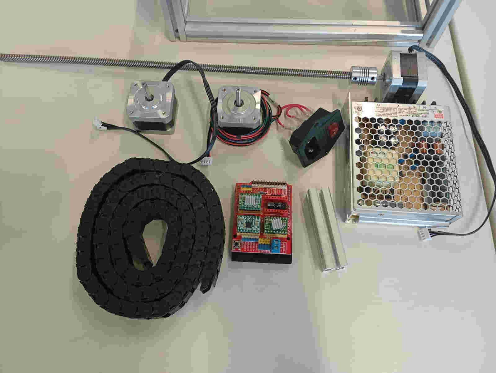
This is how we got started. Fast sketch on paper, look at what we needed and what we had laying around in the Lab. This helped
us a lot in insuring our success in a fast start. Not only did we have all the parts we needed for the frame but we had all the electronics
as well. Laying out the parts helped in the Design. In a way this was a Fab-Academy high tech junk wars. In just two days we had blown past
the deadline set by our instructor Ahmed and Top Management Leen. Mika and I managed to not just Design the majority of the frame but also
start on the manufacturing on day two.
To create LLM 3D Foam cutter (Leen Lysander Mika), the following parts will be needed to make the this CNC.
Parts list LLM Foam Cutter CNC
From Design to manufacturing
We set two goals for our foam cutter CNC.
Keeping the design simple was to with finishing our week one goal. The less mechanical things the smaller the chances to have issues with the construction this lead us to the second goal using parts in the lab. This saved time on ordering parts. Since Mika and I were ahead of schedule we proceed with the design idea quickly and could start on the manufacturing. Mika, Leen and I searched the lab for the remaining 20mm by 20mm Aluminum Profile and got started measuring and cutting.
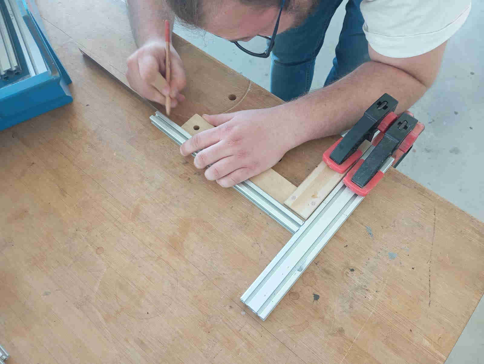
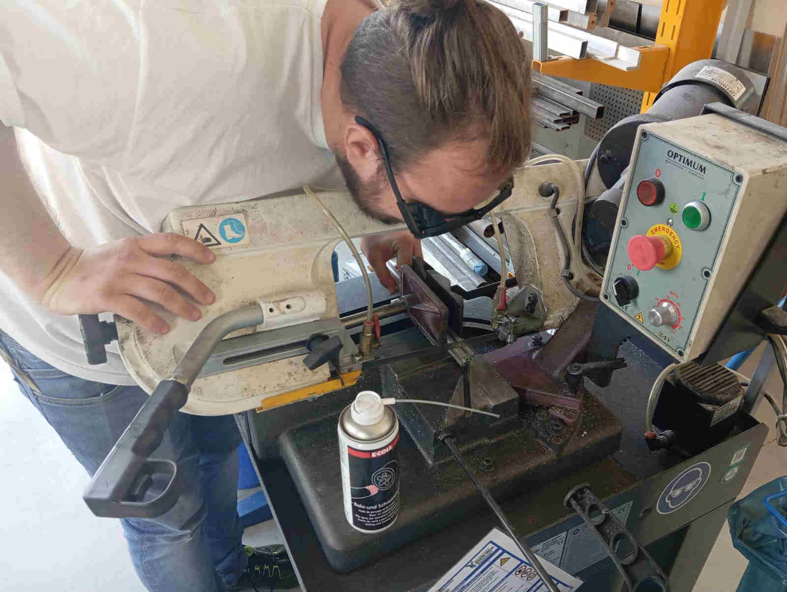
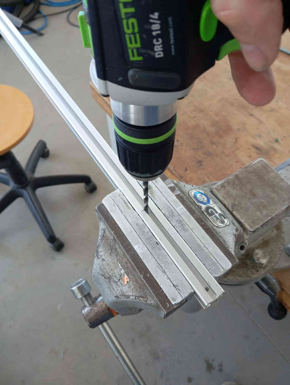
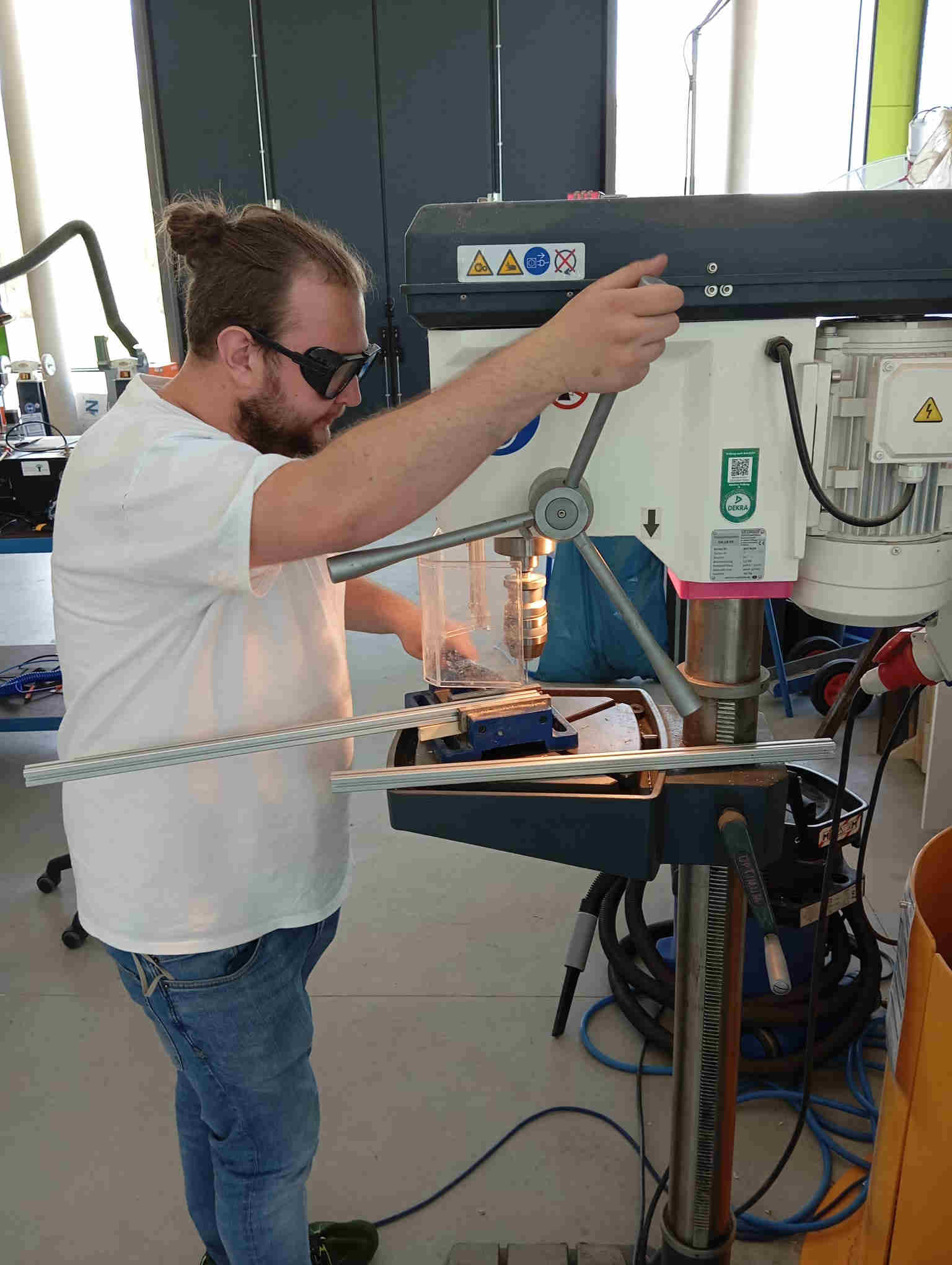
Once all the parts had all the sharp edges removed with file, we marked out where we needed to drill holes and cut the threads for the assembly of the frame. Mika got stared on the drilling of the holes while I started on cutting the threads and filing down any sharp edges.
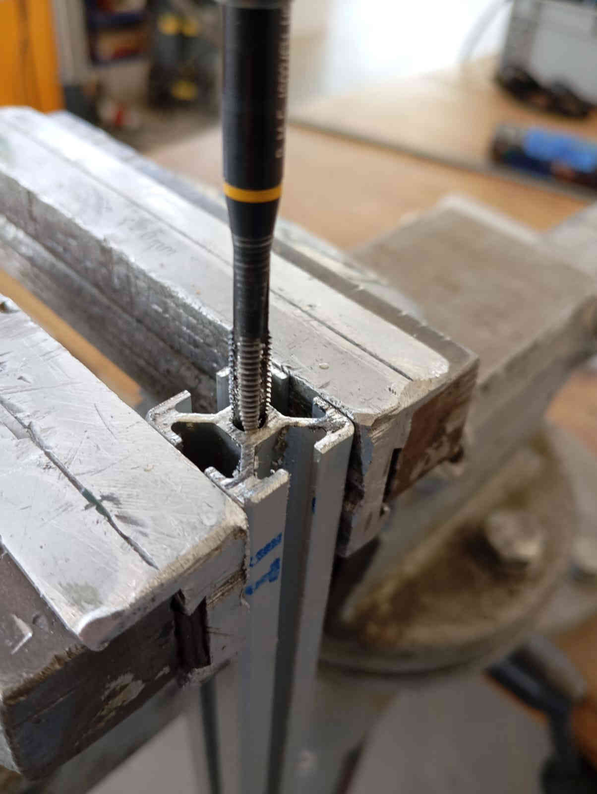
As I also wanted to join in on the fun of drilling I got the hand drill and started on the smaller parts.
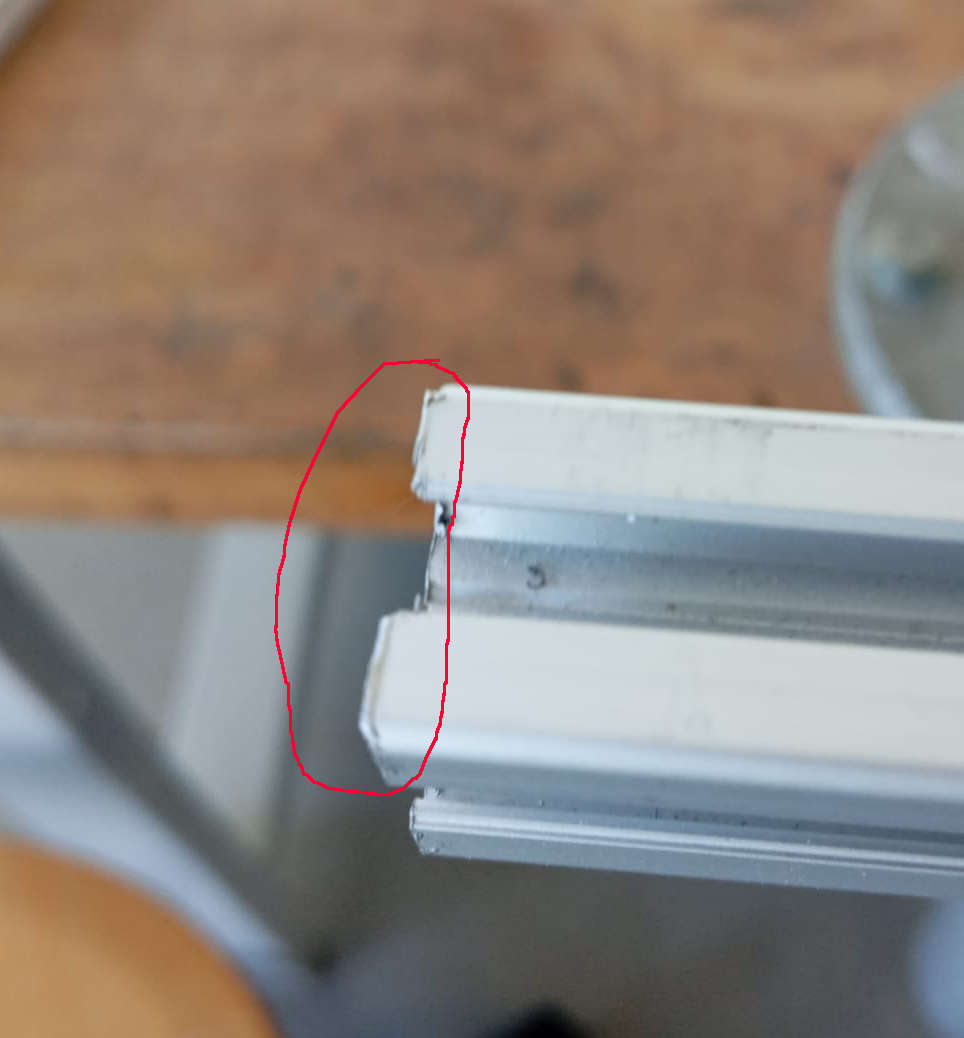
Blind Screw Joints
We thought of using 45° degree angles to join the Aluminum extrusion, but the look was not right. This is what we drilled and tapped the frames parts. This let us a bolt with wider head to slid in with the head of the screw onto on of the Aluminum extrusion and screw all the parts together. The smaller holes where drilled so that an Allen key could fit to tighten the button bolt down. Letting the frame have a very clean look.
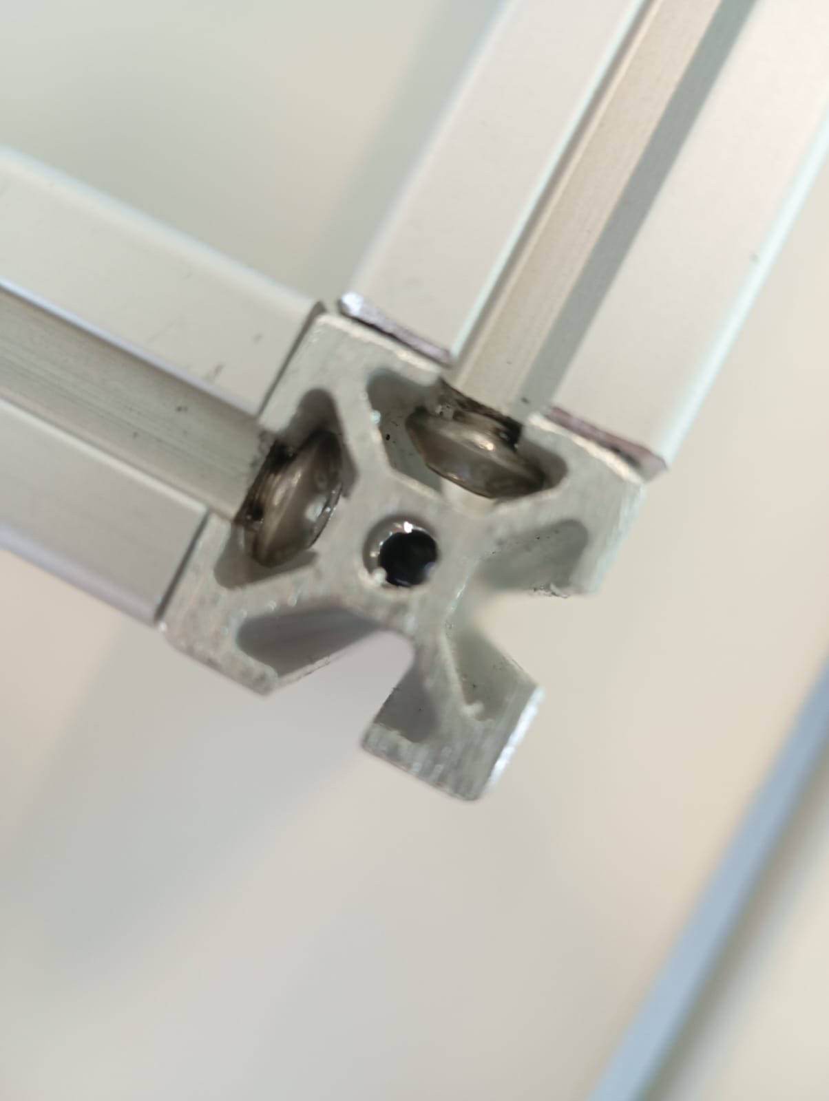
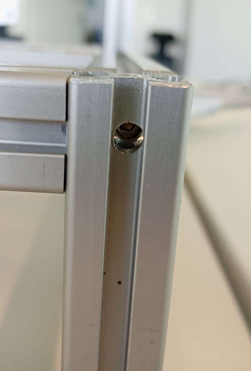
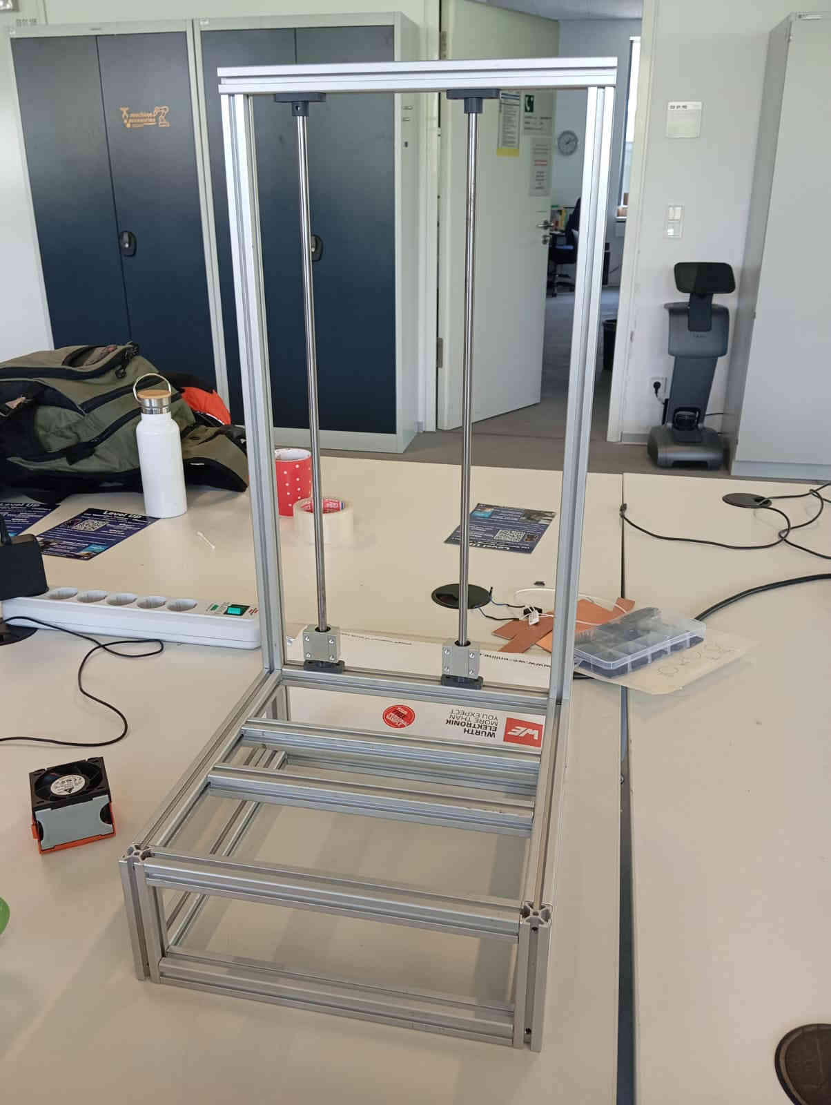
Hero shot of the frame
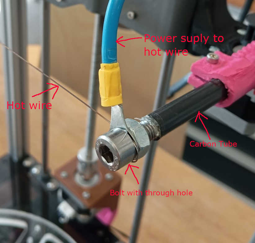
Hot wire
Once the electronics were set up, it was time to look at how to attache the Hot Wire. After looking around and trying to find some solution as to how to connect the and hold the wire in place. The idea of filing a flat spot on a M8 bolt and drilling a hole into it, where the hot wire could be threaded through. With the use of a nut we could pinch the hot wire including the connector for the power, pinching them into place. But first we glued them into a carbon tube with a two part epoxy. This worked really well.
Once Leen and I had this setup we attached a lab power supply to make a test cut by hand. Here we played around with the current as well as with the Voltage. More on this can be found on Leen's page. The video below shoes the first cut.
Once we found the right settings we did our first manual cut.
Things that need improvement
As any project, this one had its hiccups too. Building and manufacturing went well. Frame was not much of a issue and was done without a hitch.
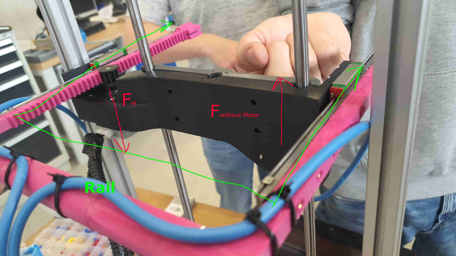
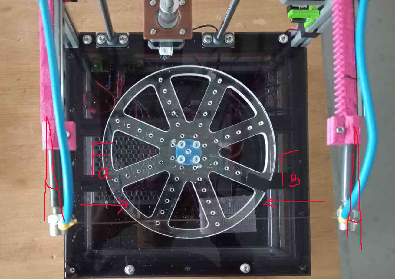
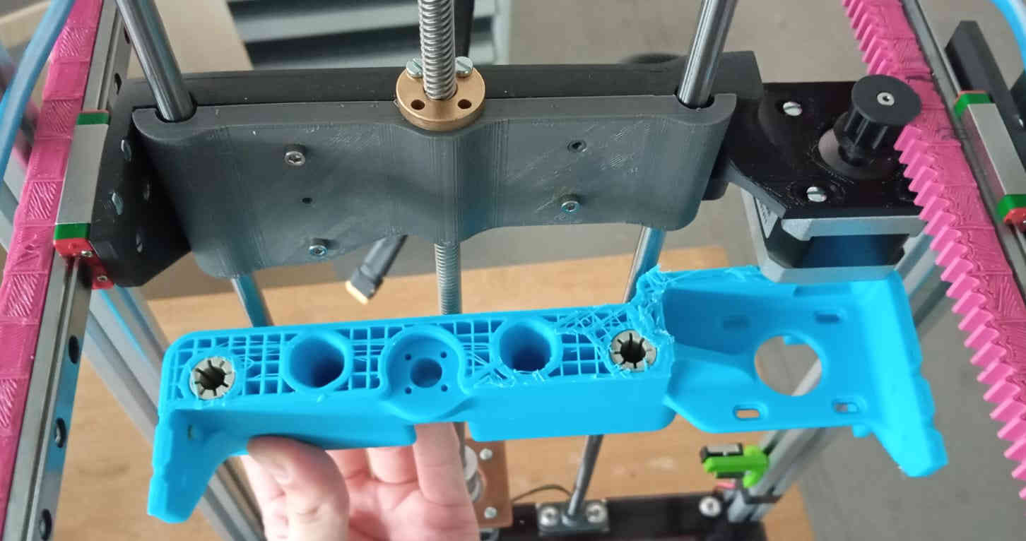
One the issues that showed and we did try to correct was with the Z-Carriage. The Z-Carriage has to carry a motor on one side, shown in the
photo as Force Motor (Fm). This force made the Z-Carriage sag to one side. We did try to fix this as soon as we saw this. The design was improved on
but the 3D print failed. After giving this some more thought, rather than printing the Z-Carriage and having the linear bearing placed in to the
print, snap rings can used to hold them in place. Allowing them to be a easy to service part. Another problem that came up was, the railing holding the
hot wire. Once the motor moves the other side seems to bind a little.
Ideas on how to fix this would be having two motors one on each side. This seems to be over kill as a belt drive system like on the early 3D printer
can be found. Here many different solutions can can be looked at. The second problem that showed, was the fact that the here marked in green rail and pinion
flexed to much when the hot wire was tensioned. All of these problems can be solved if another weeks were available. This will be things that can be addressed
once Fab-Academy over.
Last but not least
After all the stress over easter holidays and hoping that we could keep working as the labs and university is closed we managed to make a LLM Foam cutting machine. For a week build not bad overall. There was one last thing that needed to be done. A poster and a short video. With some help from my sister, as she does this for fun, helped me learn how to create a poster on Microsoft excel. The poster can be viewed on the group assignment Mechanical and Machining Design. The one minute video was made with iMovie, which comes with Macbook free to use. All in this was a fun but stressful two weeks with loads of issues at times very frustrating situations. After Fab-Academy I am would like to work more on getting our LLM Foam cutter to work better. As it would be great if it could cut foils for wind tunnels or hobby RC pilots.