08 assignment Electronics Production
This is defently not my skill set. I like my Electronics to be more plug and play. With that being said, this is
where I can start working on my final project! everthing else is easily done with in a day or two with the righrt
skill sets in being DIY person. As I want most this wind tunnel to be a project anyone can rebuild in a class rooms
or at home, I want to use what ever I can upcycle. This includes the electronics. No point in wasting money on materials
and tech that is laying around collecting dust.
Looking at the final project of all the things that need to be done for the electronics to work I made a data sheet of
what I calle the "List of Essential Components". After thinking this through of what all needs to be powered, I came up with
the following and I am not eve sure if I will not just run things off of multiple PCBs that will just communicate either manual
inputs given pushing buttons or swithes and only have sensors and data read out that gives me the infomation that is needed to+
run an analayis.
A quick run down of what I have planed: Is to power everthing with an external power supply using a cheap PC power box. This includes
the ESP32 that needs 3.3volts, this in turn will be used to control PC fans, smoke generator via Mosfet switch, DC motor using a H-Bridge
desiged in assignment 6 and one or two pressure sensors not sure which at this point. I think the analog ones will be just fine
for this project. Now in theory I do no have to pwoer the ESp32 with an external power scource, and computer could power it and reseve the
information gathered by the sensors. This may still end up being the plan, if this proves to be more complicated than was planed.
But lets have a look at our list.
List of Essential Components
How do I get started
After talking to Jure, who explained that this is really simple, I have gained a bit more confidence in what I am planning to design.
First, we need to determine which microcontroller would be best for this project. Yes, the latest and greatest option would work
faster and more efficiently. However, as stated above, working with what you have encourages creative thinking. For now, I have
chosen to use a RASPBERRY PI PIC. It has all the pins I need, and in case I need more, there are plenty of additional pins
available.
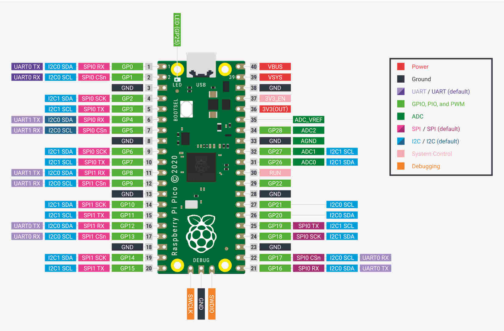
The first step was familiarizing myself with the datasheet of the board. Instead of using Google to find the board’s datasheet,
I simply went into KiCad, found compatible boards, and compared them. This process was fairly quick, and I was able to find a
board that met the project’s requirements. To hook up the fan, I needed a PWM pin and a 3.3V output pin. The PWM signal tells
the PC fan that it can rotate. But what exactly is a PWM signal, and how does it affect the PC fan? A PWM (Pulse Width Modulation)
signal is a way to control the power sent to a device by rapidly turning it on and off. In a way it is like tuning a light switch
on and off. Depending on the how fast the switch is turned on and off will let the fans speed be adjusted.
Creating the PCB
After burning my own Arduino, and yes, it stinks when that happens, I’ve learned an important lesson: always make sure not to mix up your ground and positive connections. The second lesson is that I should have checked everything with a voltage meter before hooking it up to a microcontroller. Being brought down to my knees by this mistake, I’m now 100% certain that I’m just a guy who should stick to mechanical things and get outside help for electronics. But as I do not give up easily, I kept going and with the help of my instructor, I now have come up with a board that will have: extra pins (incase of upddates), 12volt external power supply, a voltage regulator 12V to 5V, LCD screen, LED lights to backlight the tunnel, a load sensor to gauge how much lift or pressure acts on a object, and lastly a conection for the PC Fan.
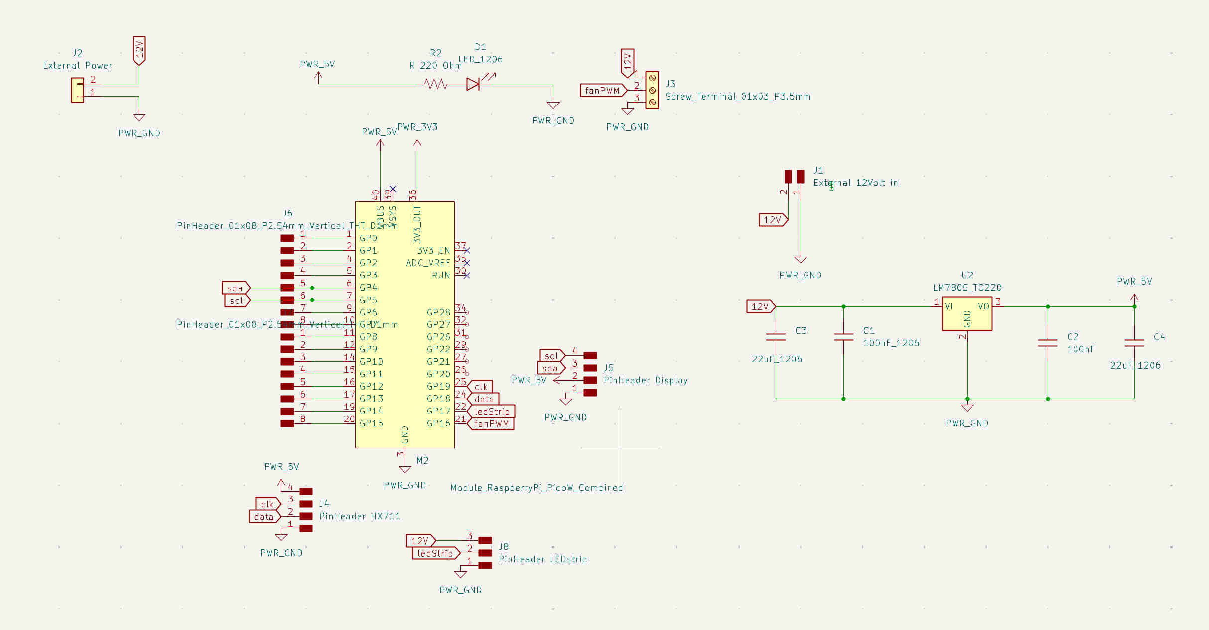
Creating the PCB I used KiCad, which we learned how to use the Assignment Electronics Design. Having my list of parts and that can be
incorperated, the looking at the datasheet we placed everthing out starting with the Raspberry Pi Pico. As there will be an exteral power
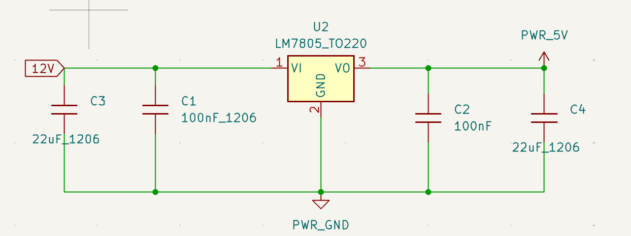
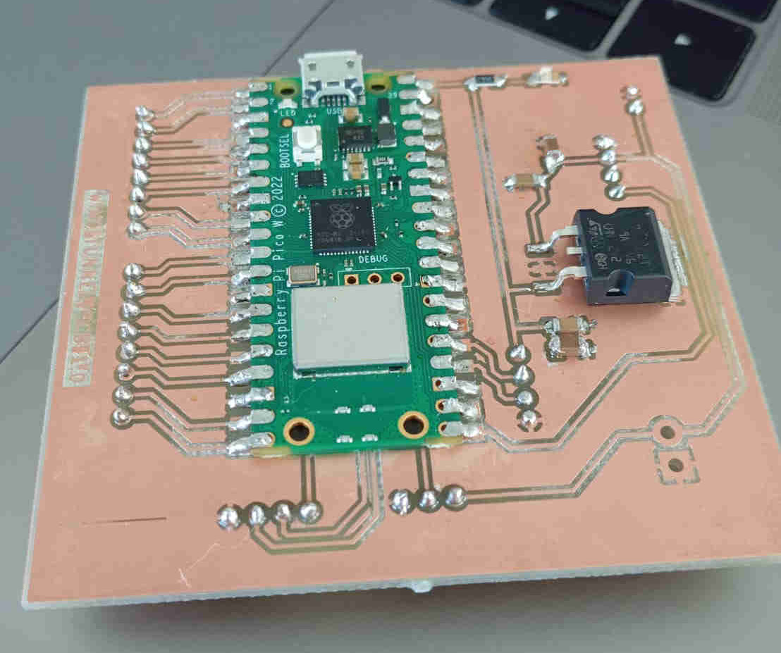
supply A Voltage Regulator is needed. This will help power the Pico, LED Strip and the fan. The voltage regulator has 4 capacitors, two 22uF
and two 100nF with a LM7805_TO220. The LM7805_TO220 is a 1A 35V Linear Regulator that will step down the power.
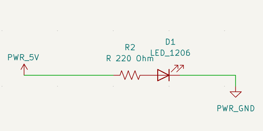
Next, let's look at the Raspberry Pi setup. While reviewing the datasheet, we noticed that it does not have any LEDs on the board to indicate that it has power. This was easily added using a 200 ohm resistor and an LED connected to the 5V power supply and common ground.
Looking at different LCD screens on the www.az-delivery.de and not finding a datasheet I stuck with what was on the module board that comes with the screeen to figure out what pins are needed to connect to the Pico.
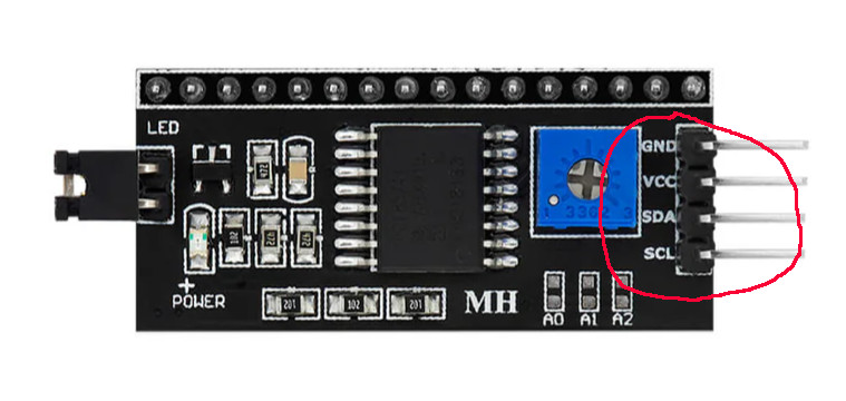
Knowing what pins were needed, a 4 pin headerpin was added as well as the connections on the board.
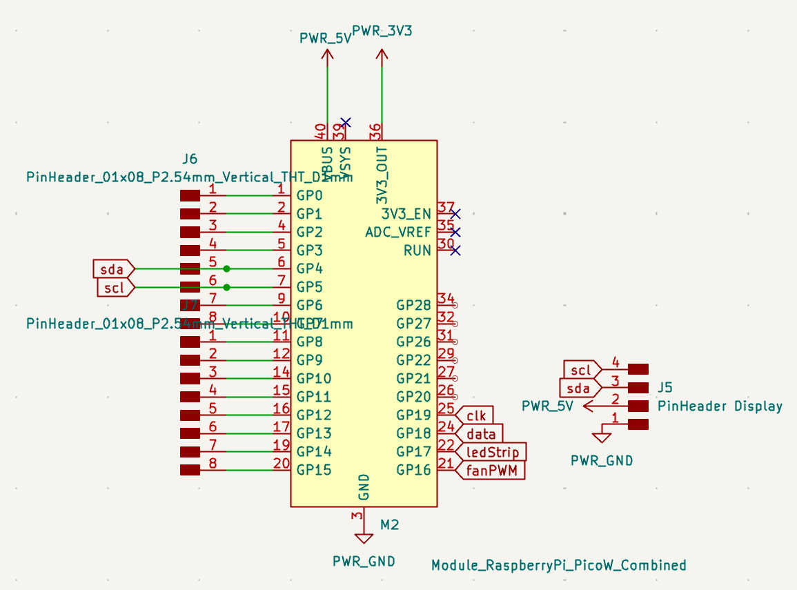
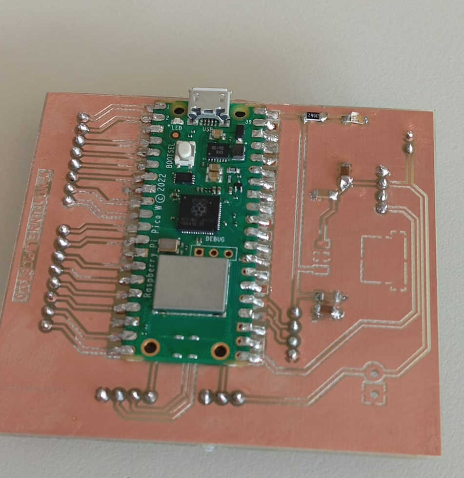
As this board my develope more ovet time, extra pins were added as well. The full layout of the schmatic is rather simple once you know what you are doing. I hope to keep learning how to do this, making your own PCBs for other projects will make them look cleaner as there will be no protypoing boards attached to breadboards with wires going everwhere. I hope that with this PCB I will have my finail project looking smart. The image below is a full view of the current setup.
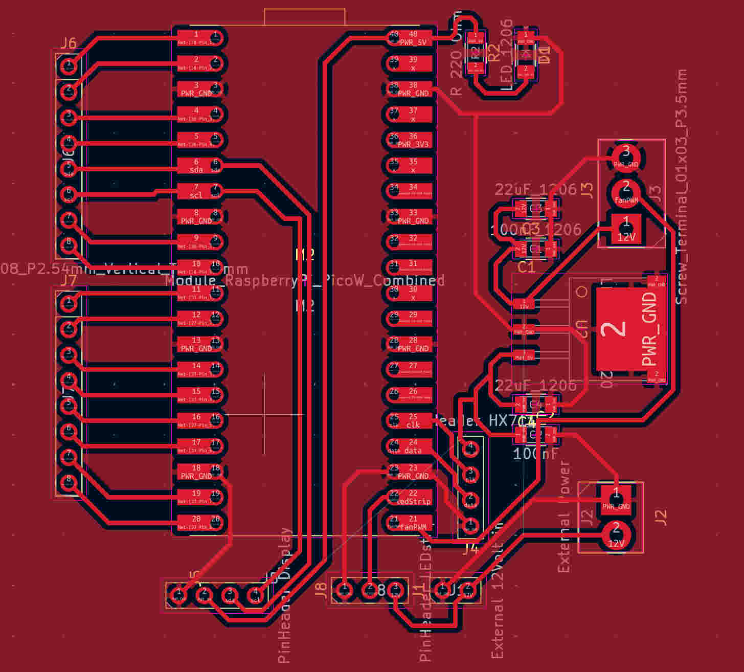
Setting up the PCB
Setting up the PCB depends on how you want it to function. I chose to keep it simple by arranging all my connections in a way that avoids unnecessary wire crossings. This meant placing the external power supply on one side of the board and all other connections on another side. This layout makes it easier to locate the necessary connections and helps keep the wiring loom clean and organized.
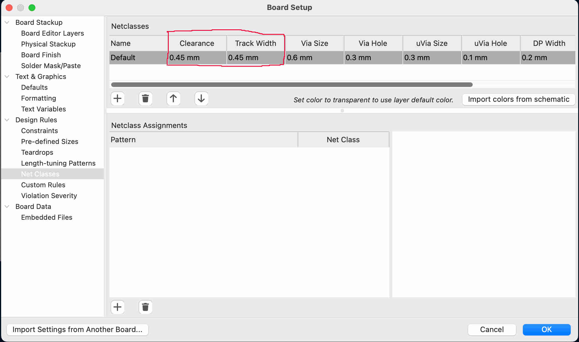
To insure that the PCB works and gives us a good trace, even though we found out group assignment that we can get really good traces we changed the taces width.
Lets Mill a PCB
We will be using the same PCB milling machine as in our group assignment.
The copper layer is 35uM thick, the main board material is if FR1. The first thing we want to check what material we are
using. This is due to the fact that some of the PCB boards being used can be hazidous for your health. The board that was used here
is safe even if the machine would not have a vaccum and was not sealed of. The other option of material and most commenly found
FR4 contains fiberglass particals that can cause irritation and can hurt your health overall. Always check what materials you are
using and take proper care to protect your health. It is worth in to buy the right resperator.
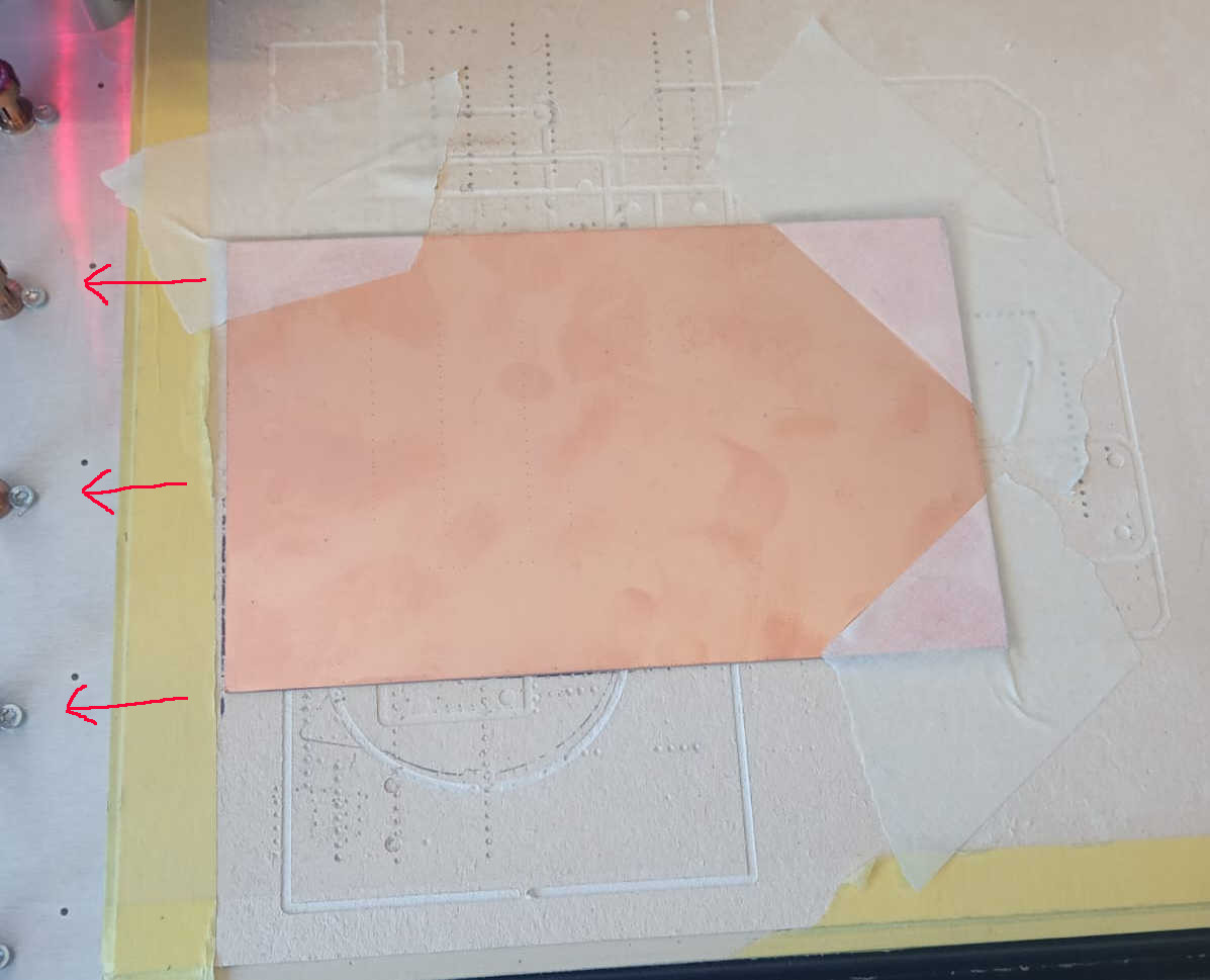
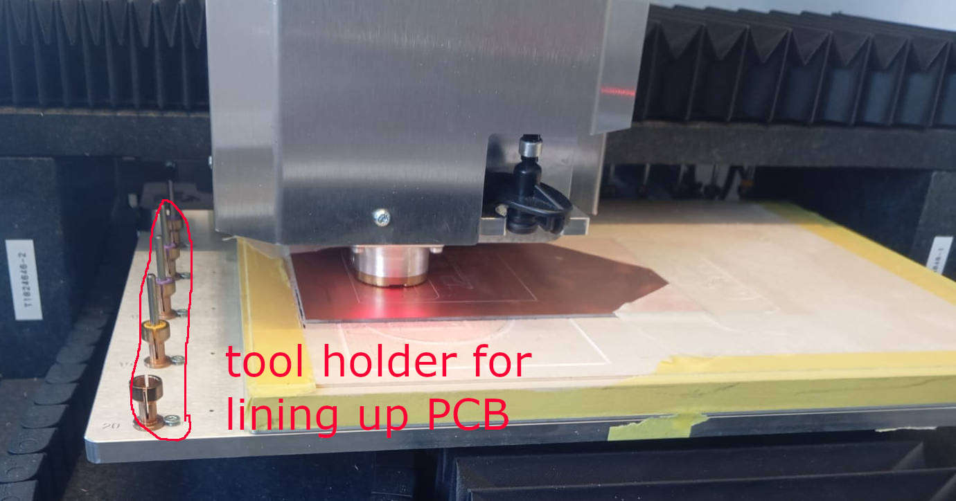
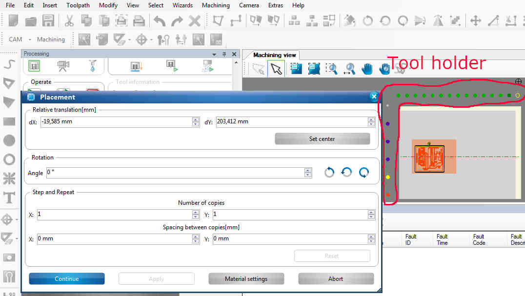
Next step is to place your PCB board in the LPKF machine. This specific PCB mill has markers in form of the tool holders along the sides.
This helps you place the baord and tell the cnc where the board is localed arccording to the tool holder. Once alianed we add tape to help
the board stay in place, just in case the vaccum stops working. See images below.
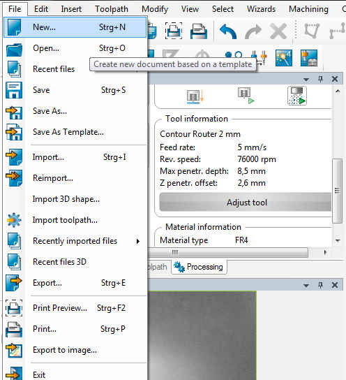
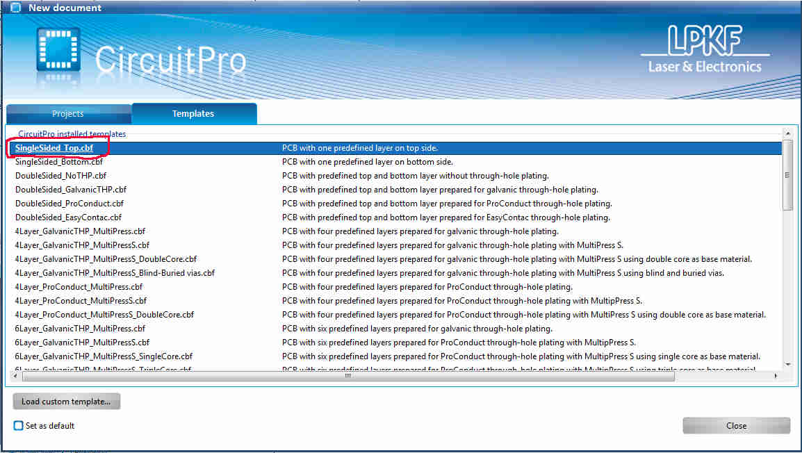
Now we will repeat the steps taken in the group assignment. As you can see the tool holder are also showen in the software, as stated before this helps with the alianment of the board. To continue we want to go to File > New and select Single Side Top. The reason we pick this is our board is a single sided PCB.
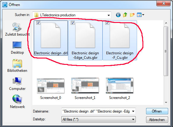
Next we need to import three files. To do this we go to File > Import. Here you want to import the following files, gbr and drl which can be
created in kicad. Here you can down load the gerber files.
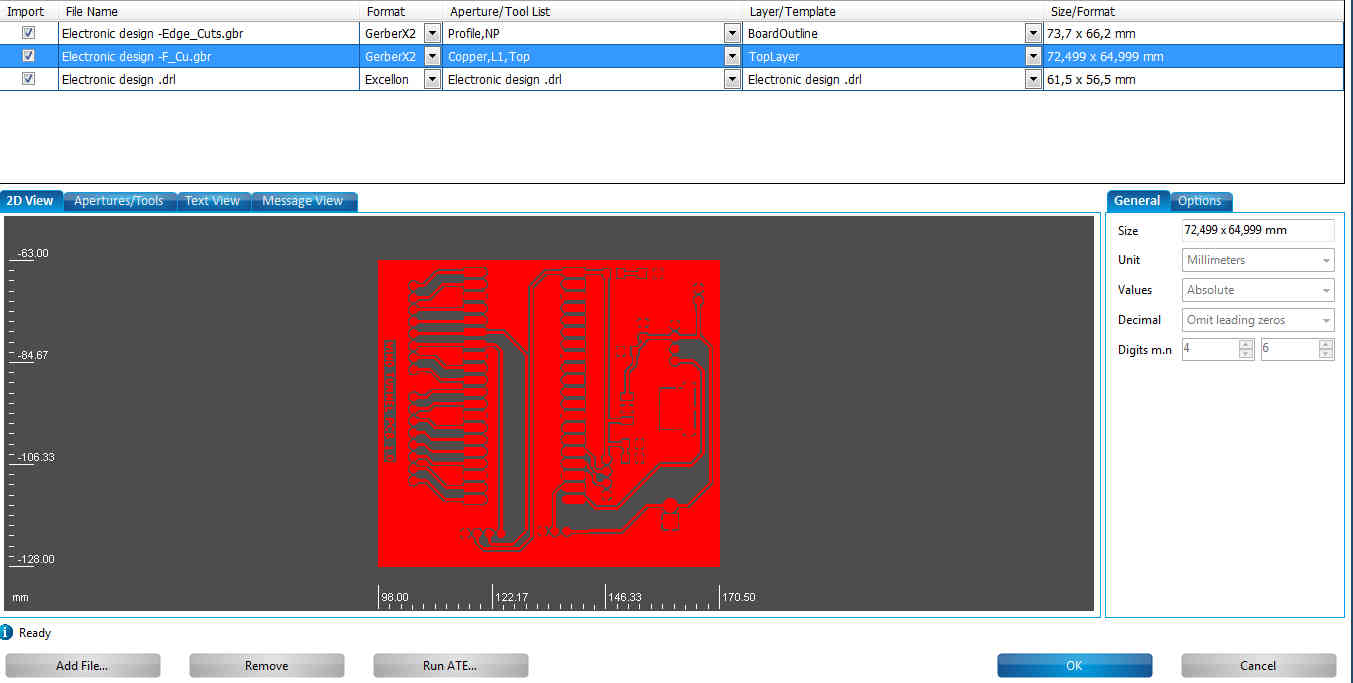
Once you have selected all the files, it will show each one of them and there layout as to what they do. You can also change the and ajust setting like drill size, milling depth, and so on. Here I will surgest talking with your instuctor, some of the setting are vital to keep the tools shart and in good working order. At this point I myself have not fully understund the machine, but most of the functions are simulair to using a normal CNC. As you can see depening on what file you have selected the software will display the operation that that the selected file will do.
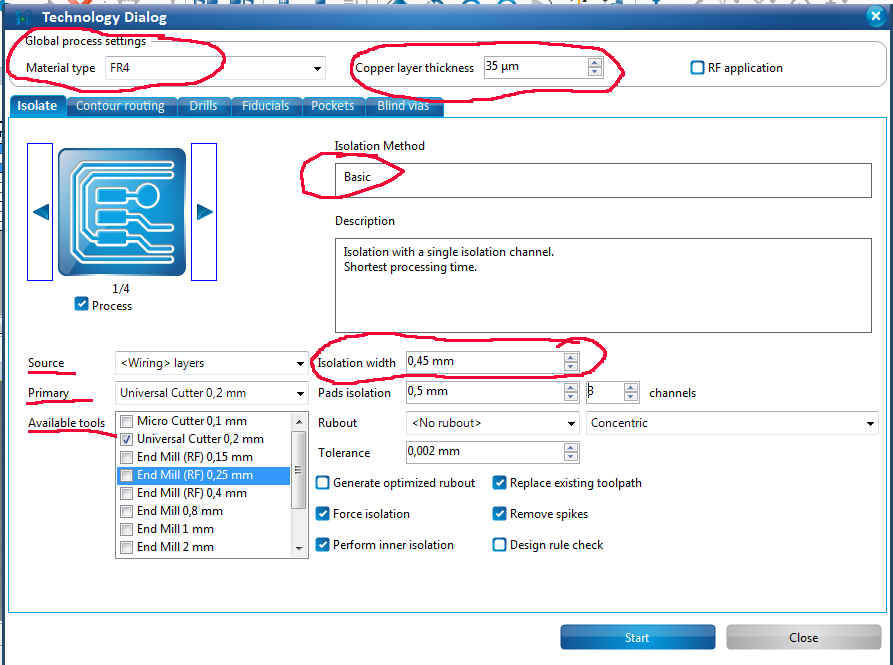
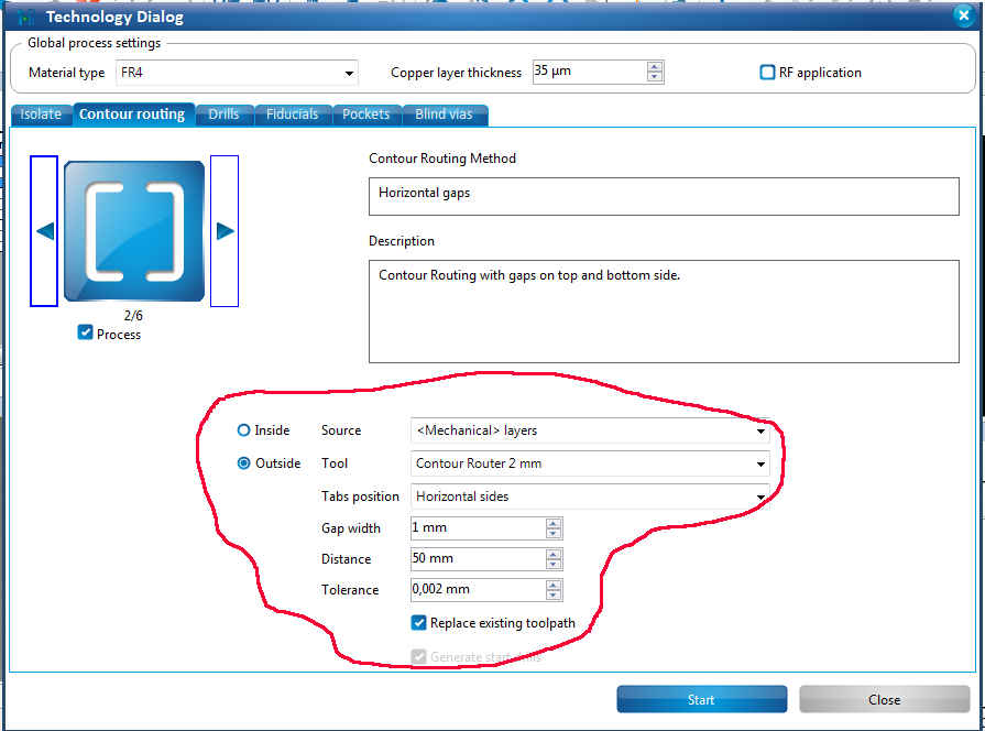
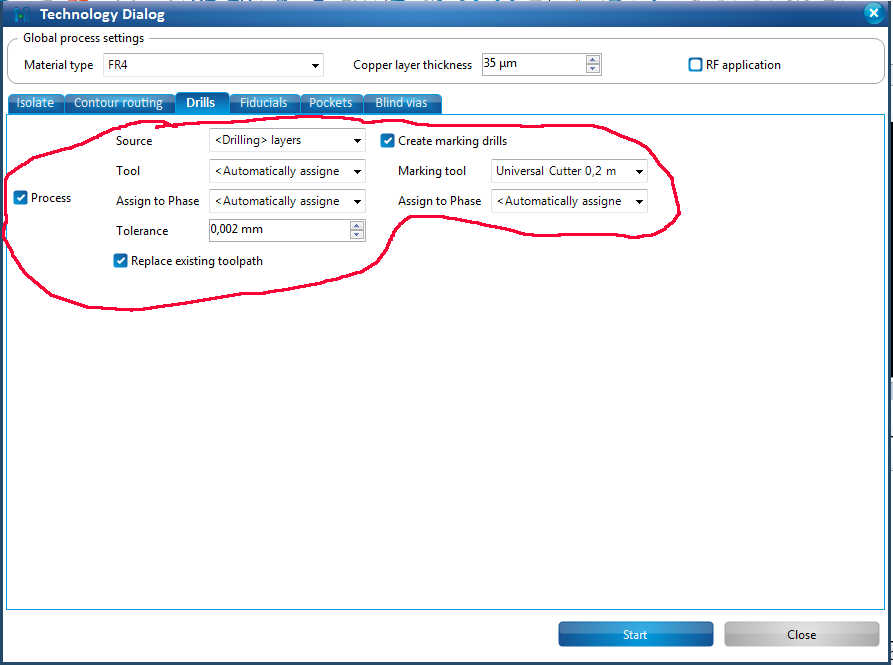
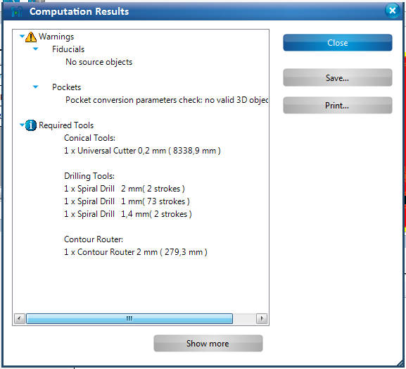
Int the next menue that pops up you add additional information that about the board. Add things this like true width in mode and in Tech the function of drilling, wiring, and mechanical. We also want to add the layer thinkness as well as the width of the trace that was selected in KiCad. Doing this insures once again that our layout will work when completed. Here we make sure that everthing is selected that we need to start the process of cutting out PCB. First image shows the wiring, seocnd image countour route were added a small tabs to hole the board in place, and the third image shows the drilling operation and tools selection, forth image will show that there is a waring on this case we can ignore. The reason that we can igrone this, is that we do not have any of those feature on our board.
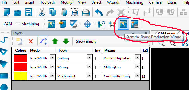
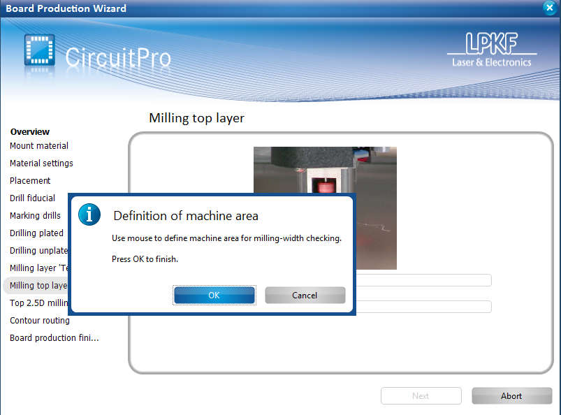
Last but not least, I mentined that we used the tool holder along side of the milling bed to alian the board. This will now help us with telling the machione where the board is. We want to open start board production wizard. Once we selected the button a pop up window called placement will open. Here along the the left and top side you will see that there are the tool holder are displayed. Rest of the placement is done with the manually. Machine does have a built-in camera, but this takes takes more time to set up.
Cleaning the PCB after milling
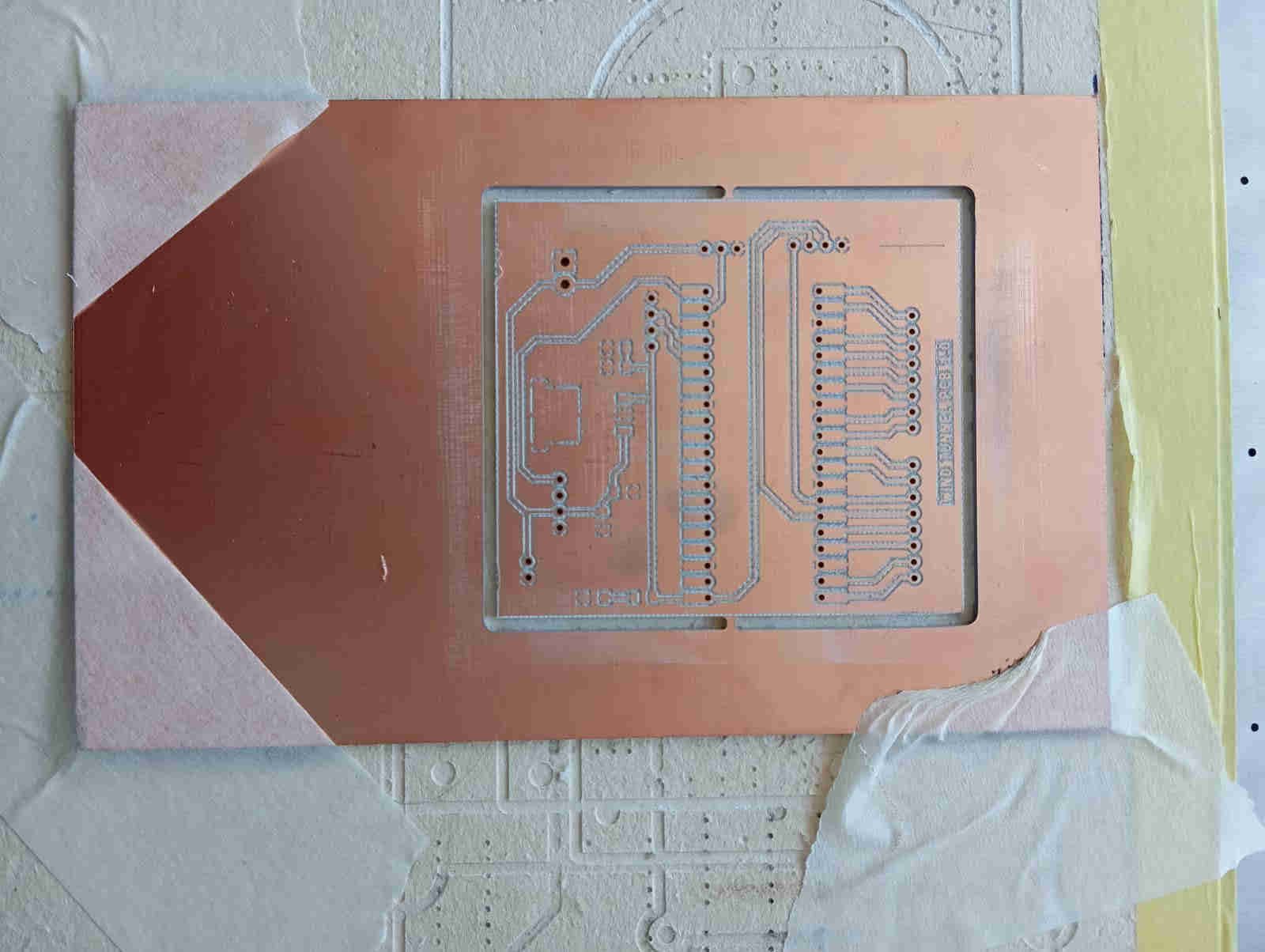
Once the machine has cut/milled the PCB, we need to remove it and detach the PCB from the rest of the board. Once this is done, we wash the board. Why do we need to clean the board? The reason is simple: after milling the PCB, there will be some copper particles and copper hairs that could short the board. How do we do this? The best way is to wash the board with a sponge and some water. It also helps to use a Scotch pad to scuff up the surface. This process removes any strands that may still be attached to the board from the cutting process.
Soldering the Board
Next comes the best part and the part that I enjoyed the most. Soldering is done with the help of a filler material called solder.
This filler material is used to join two metal surfaces together. This is great as we have a lot of small parts that need to be added
to our PCB. In today’s age, we want our electronics as small as possible. The downside of this is that these components are now just
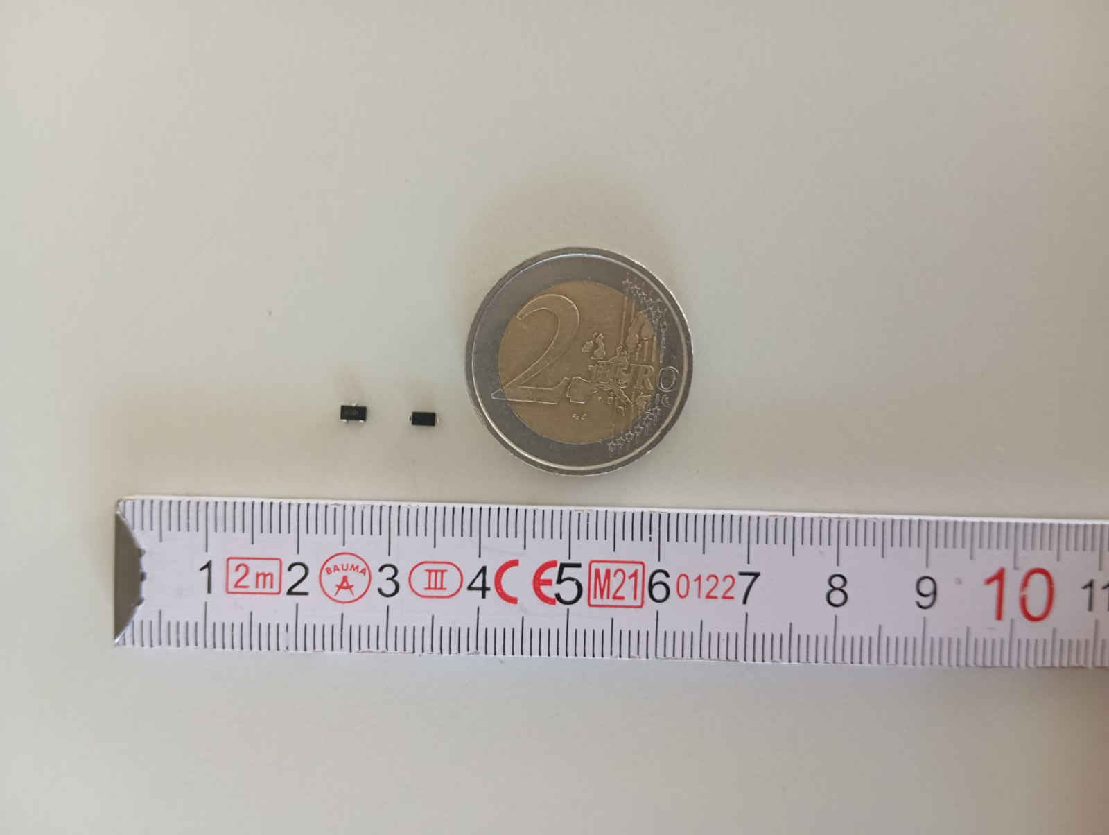
millimeters big. This was a challenge as it is harder to solder than through-hole-mounted components. These are all surface-mounted.
What helped me here was to tin the mounting surface before placing the component on the board. This let me heat the area up and join
the two surfaces together. Once placed, it made it much easier to add a little more solder. I do have to say that it was really hard
to solder in comparison to through-hole components.
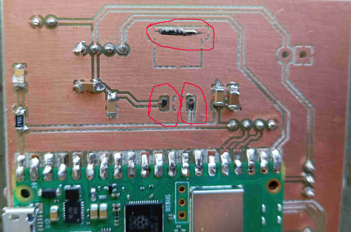
Next and last step is to check the board for issues using the multimeter. To do this we check for continuity, the Multimeter should make a beeping sound
if there is continuity. This will not work with resistors. In this case we find a room that is some what darker, as the LED will give of some light through
the multimeter while checking continuity.
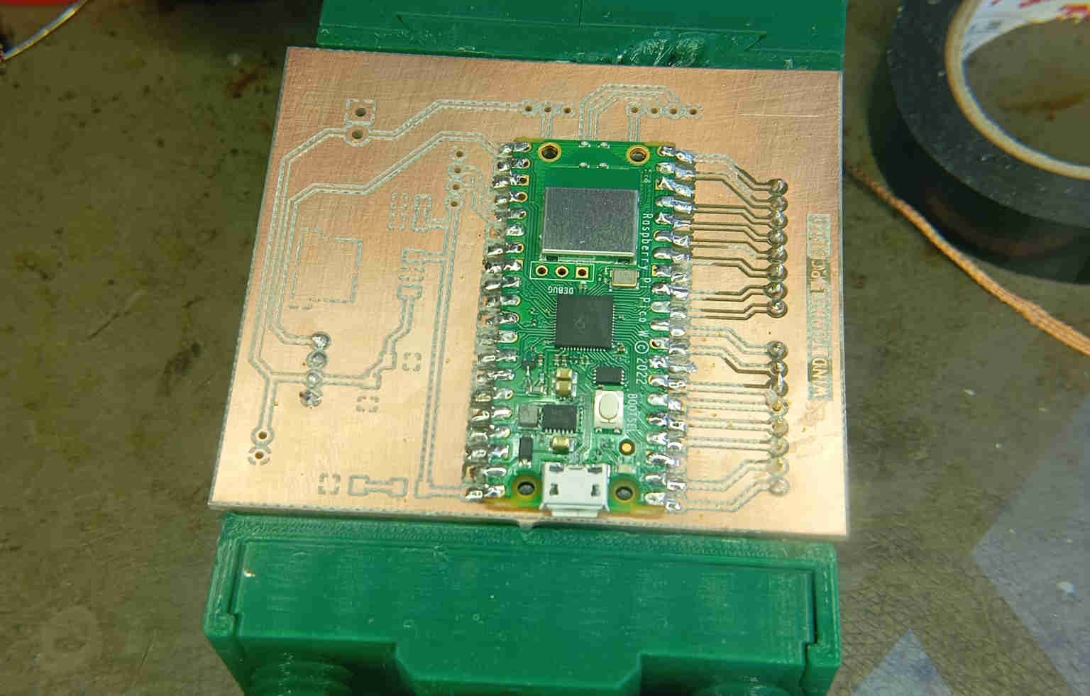
Hero shots of my first ever PBC
Loading a code
Now that all the connections have been tested with the multimeter, lets upload a code and see if we have a board. For this
you want to have Ardunio IDE installed on your PC. After installing we want
to also check what board is being used. In this case the Raspberry Pi Pico W is the main micro controller. Now you can downlod
boards from the Arduino IDE library, but here my instructor surggested that we want to look for the download.
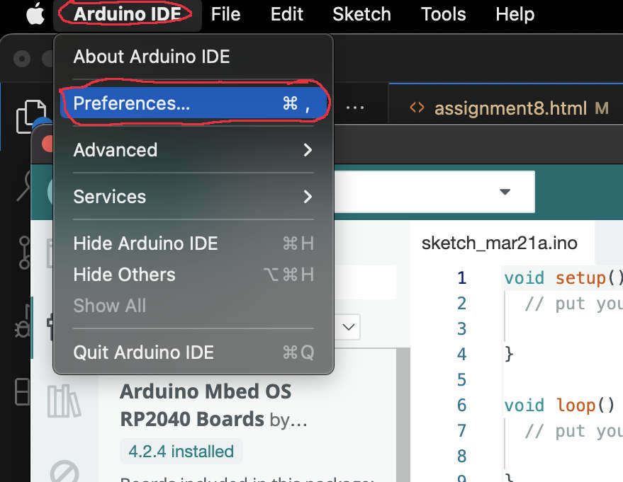
To install open the IDE and go to Arduino IDE find preferences. Once in preferences we add the json link and click okay. This will
start the downloading process. Once installed we can move on to loading a program onto the board. Copy and past the following
"https://github.com/earlephilhower/arduino-pico/releases/download/global/package_rp2040_index.json" to install this board the
Raspberry pi Pico W.
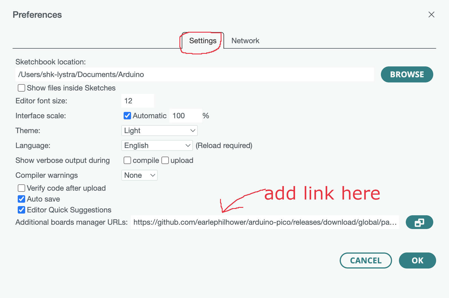
This now gives you access the board with the use of the Arduino IDE. Now we come to this weeks last task. We want to run a program on
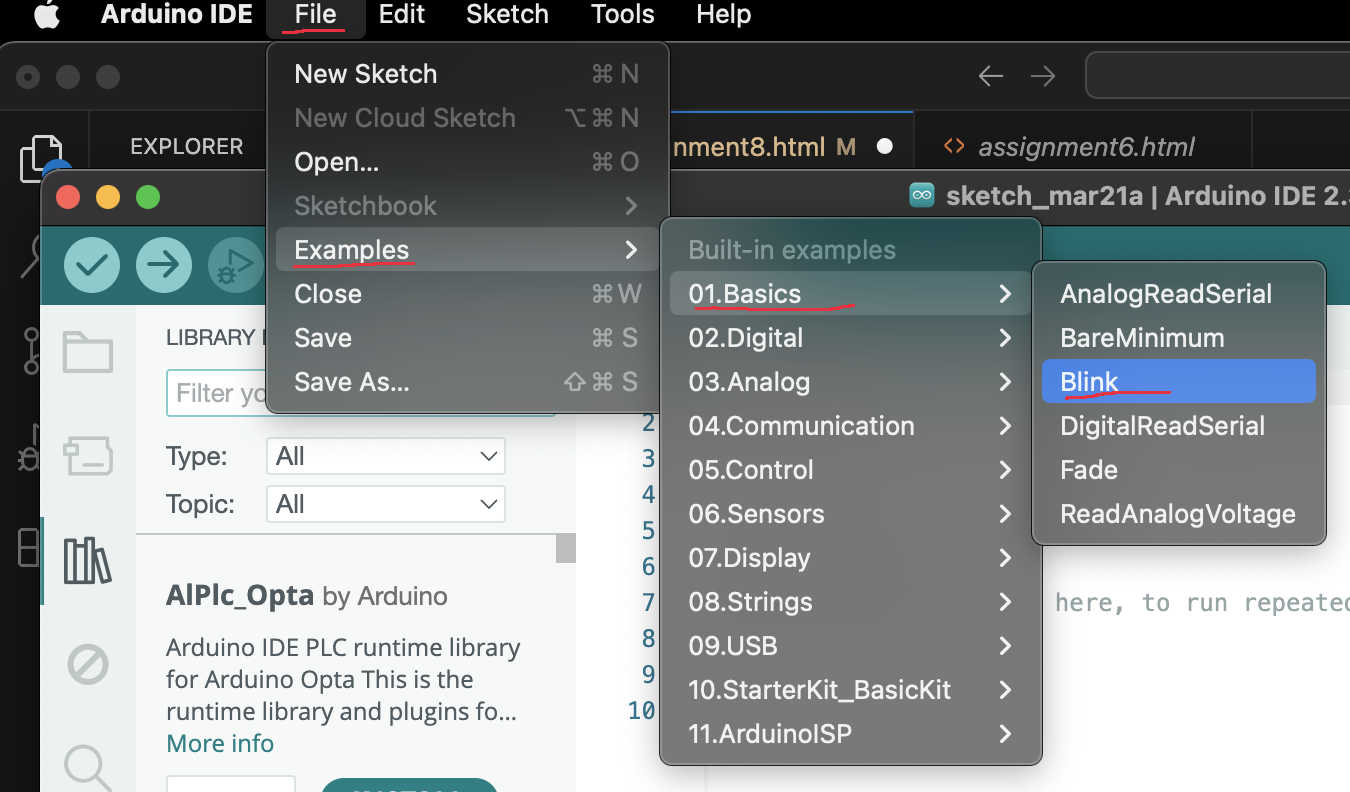
our PCB. As the board has a build in LED we can do the worlds second most famous code: blink. For this we can either write our own code
or we just go to File > Examples > Blink. Next we connect the board to the PC check if we have power to the board. As there is a LED
that was added to just to tell us that the board is getting power this LED should light up. Once the board is connected we upload the code
by simply pressing the upload button.
If all went well we should have a blinking LED that blinks every second and a LED indicating that the board is reciving power form the 5 volt
pin out.
Running on 12 Volts
My conclusion
Still in progress. I stated at the beginning of the week that I am a mechanical person. I still think this,
as I feel I understand what I am looking at when designing and building anything. This brings me back to the
freaky thing called electronic design. After long talks with friends and my instructor, I have learned how
to approach the design of electronics, like making a PCB. It can be simple if you take your time and someone
shows you the important things. Here, I really did learn that I was overthinking the assignment and that
data-sheets help a hell of a lot. Once you get used to looking over them and knowing what to look for,
it starts to make a lot more sense.
I am weird in that I need a good example to watch the first time I learn something new. Being able to
see how things are done helps me understand what to watch out for. I have always learned this way, and
one of my teachers once told his other students: Mr. Trapp is stealing again with his eyes! He was right,
I can look at any task being done and learn from it really fast. That being said, I hope to continue
learning this way, even with electronic design.