17 - Applications and Implications, Project Development
There are many questions around any project. These will be answered here and summarized, such as cost and applications and future plans. Looking over the questions lets get started with the second to last assignment.
What Will It Do?
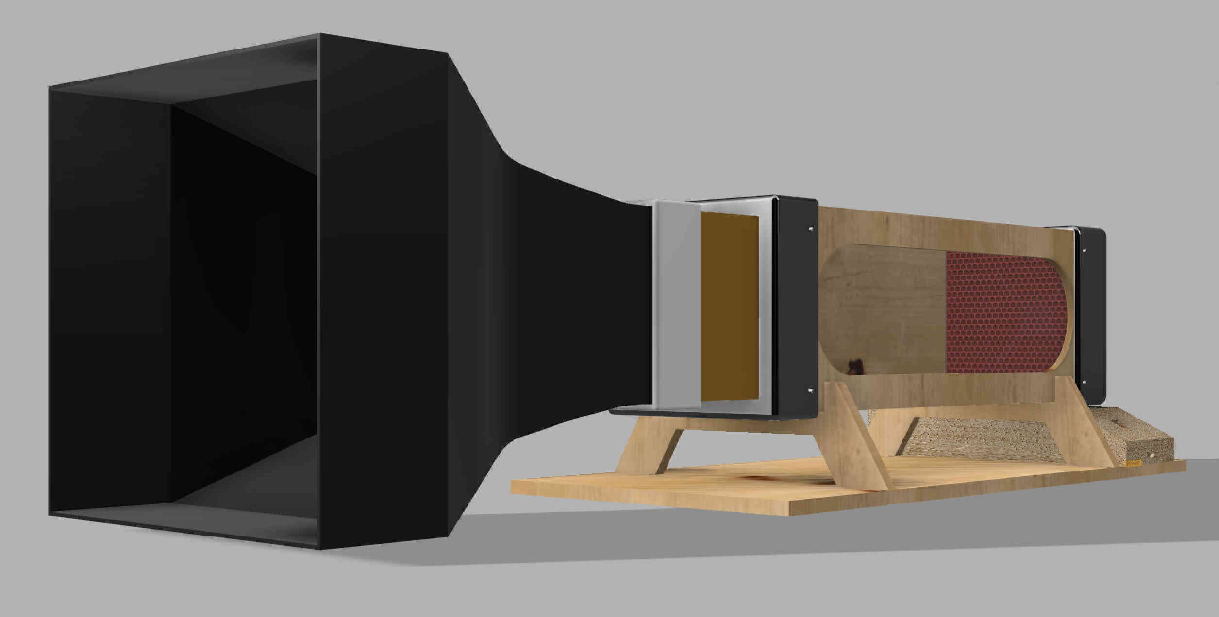
This wind tunnel enables the visualization of airflow around various objects, such as airfoils or spheres, to better understand aerodynamic behavior. In addition to observing flow patterns, the tunnel also facilitates the study of lift and down-force generated by these objects. Designed to be compact and portable, the wind tunnel fits easily on a classroom desk, making it an accessible educational tool for students to explore fundamental principles of fluid dynamics and aerodynamics firsthand.
Who has done what beforehand?
The one of first wind tunnel ever built was by William Charles Kernot in 1893 in Australia at the University of Melbourne. Just a couple of years later the Wright Brothers build a wind tunnel at MIT. When I was in the 8th grade I watched a PBS special on the flight and ever since I have wanted to build a wind tunnel. As to who has made their own Wind Tunnels in Fab-Academy, there are a number of people, I mostly stuck to what I had read over the years and multiple papers done on the subject that I got access to from a Professor at my University. Even reading a paper on flow tunnels, and a lot of NASA paper from the 80's.
What will you design?
I have always thought, if you want to understand how something works build it yourself. There are exception to for some of the electronic components
that were bought. All other parts such as:
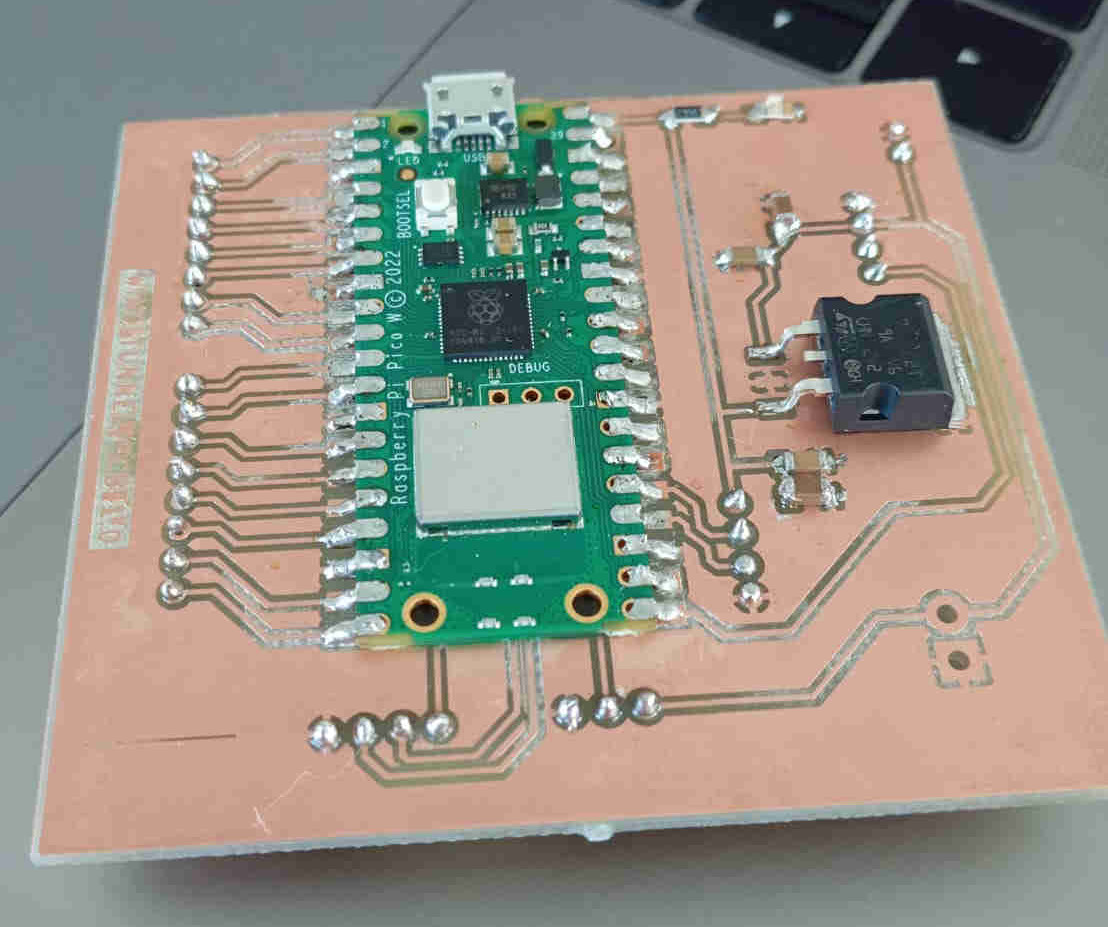
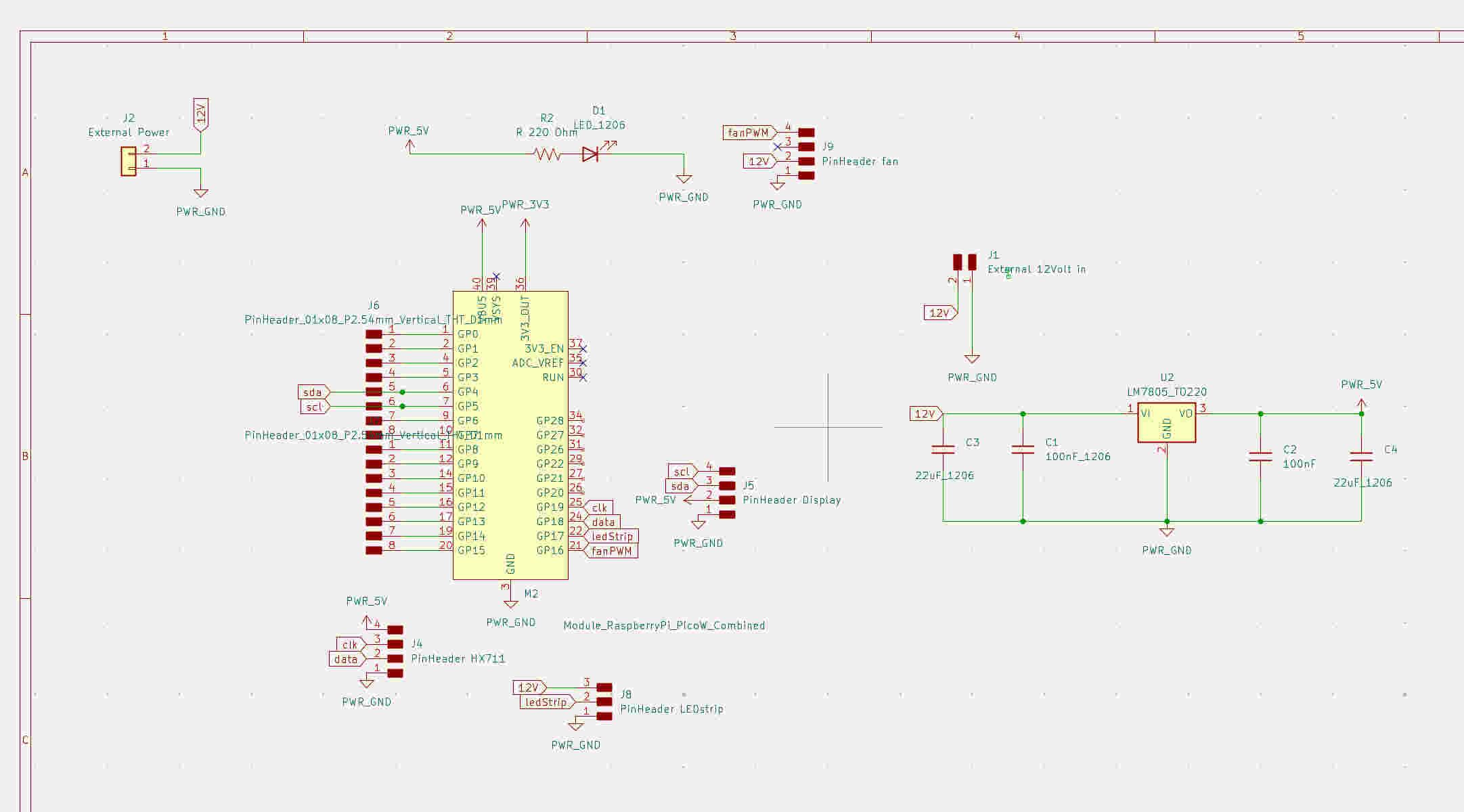
This initials a fully custom PCB design with a Raspberry Pi pico W as the main micro-controller and the interface that allows for control of the tunnels sensors.
What Materials and components will be used?
The materials being used are mainly PLA and Plywood for the main parts of the project. Other materials such as the PCB will have
a small small amount of cooper and some electrical components. The list will be dived up in to materials and the components made
out of the materials. The total cost of all parts will be listed with each part of the build.
Parts made 3D printed of PLA
The total amount of PLA needed 3kg
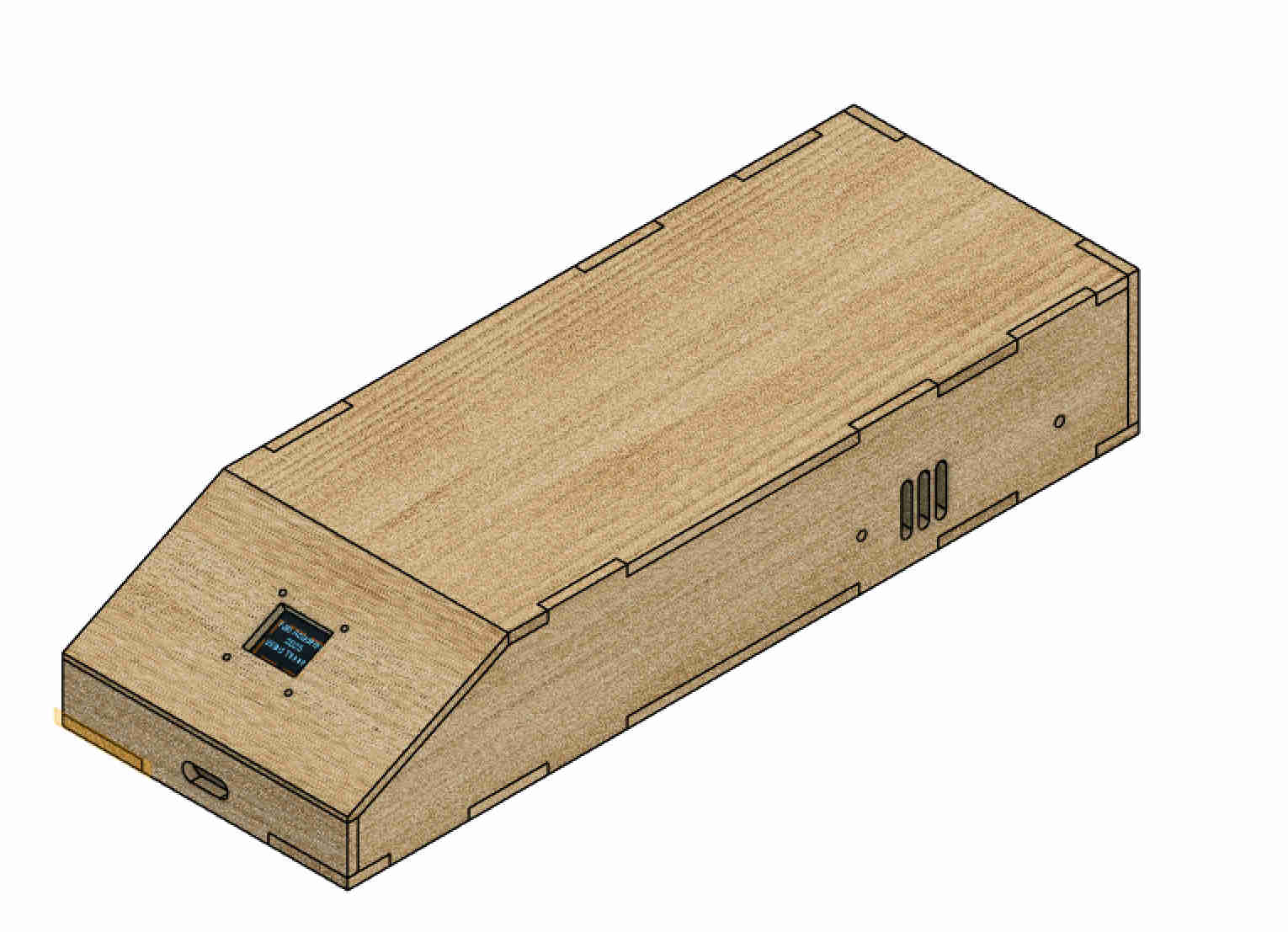
Parts made of 12mm and 4mm PlyWood
For Tunnel and Stand total wood needed is 0.500m cost of a 1m^2 at 20 Euros
Electrical components PCB
Electrical whole components
where did they come from?
Many of the electrical components came from the Fablab in Kamp-Lintfort. Others had to be soured from the online stores such as Reichelt and AZ-delievery for all the electrical parts. The wood can get sourced locally at a home improvement store including materials. The PLA can be sources at online stores such as 3D jake. In this case it was provided by the Fab Lab and the other sources at the University.
What process will be used?
The processes used to make the components for this project are: laser cutting, 3D printing, CNC, and soldering. The electrical housing can be cut with a laser cutter. Many of the component will have to be 3D printed which are all the parts made of PLA. The main tunnel will be cut on a CNC. The same with the PCB, which was cut on a CNC and later all the components will be soldered by hand. Other process such as drilling of holes or cable channels cab be routed with a router or created with hand tools.
What questions need to be answered?
This project raised many questions even before the first part was built. For example: How can I determine the flow rate? How can I ensure laminar flow in the test section and what exactly is laminar flow? Then there were technical considerations: How should the PCB be designed? What components are required to make the electronics function properly?
These questions often led to further challenges. One of the biggest uncertainties was: what could go wrong along the way? Some answers can only be found through experimentation. For instance, how can airflow around an object be visualized without using a fog machine? What alternative visualization methods could be explored? Each solution seemed to raise new questions in turn.
Another key question was: how can we measure what happens when an object like a model wing or car is placed in the tunnel? Understanding the forces at play and capturing accurate data became a central challenge.
These are just a few of the many questions that arose during the planning phase. Most of them can be addressed by studying similar experiments and reviewing relevant research. But some—like whether the load cell will detect measurable forces or whether the code will function as intended—can only be answered once the system is fully built and running.
Certain questions that may seem essential to others, such as how the parts will be fabricated or designed, did not arise for me personally due to my prior experience. However, they are still valid and important for others approaching a similar project.
Ultimately, one question remains: Will everything work as planned?
How will it be evaluated?
>How I would evaluate this project is based on the features of the wind tunnel. Looking at the project from an outside point of view, I would look at these points to check it the project is successful:
What tasks have been completed & What tasks remain?
At this time the tunnel is 95 percent completed. All major components from the Air-Intake to the Defuser are completed and been assemble. The pars that are left is assembling and testing the water vapour distributution system and it electronics to control the on and off the water vapour. The other part of the the project that still needs to be worked on is the programming to insure that all the systems are properly working with each other.
What has worked & What hasn't?
Looking back over what I have done in the past months everything has worked out. There where a couple bumps along the way, but nothing that could not be fixed. The one issue that gets me worried is the load cell, as I had really hard time to get sensible readings. Everything else worked out as expected. None of the machining was much of a problem. The tunnel assembled as planed with little adjustments here and there.
What questions need to be resolved?
The only question that needs to resolved now is the about the water vapour distributution system. As I found out that one is not enough to show the flow in the tunnel. This is the last part of the project that needs to be worked out. Will it need a container to pull the water vapour in to the tunnel? And will I need more than 4 Humidifier modules to make this work?
What will happen when?
At this time the project is going to be complete wether I need to be spend a couple nights programming and stressing is not of any relevance anymore. The project is coming to its end and I am happy as to where I am at this current time. Even if once of systems fails, there are plenty of other back ups that will show a result.
What have I learned
What I have learn throughout this project is that anything is do-able and that everything electrical will have a issue. The most
important part that I have learned is that PCBs are not at hard as I though before. If you look at the data-sheets of the electronics
that you want to implement, it is fairly easy. It can be tricky and I am still all for asking for help when it comes to electrical
components. Especially after today adventure where I managed to shock myself with 230volt, with the power switch turned off. Many of the
things that I have learned have just improved my skills even more. Somethings I knew before hand and where a nice DIY test to see how
much I still knew or skill sets that could have been improved.
From my final project I learned a lot of new maths and that not everything comes down to the theory of a project many things
I did were based on design and intuition from my past background. For example that air-strainer should haven been according to the
math 50mm longer to create the laminar flow. What later on in the project reviled itself to be really good at 100m length. I did how
ever also add a second air-strainer on the exist side of the testing sections which decreased any issue of blow back. Another fact
that was reviled was that with a slower flow of air the laminar flow was increased. Thanks to Mika trying to mess around with my
experiments. Thank you for the help in fixing my the Problem I was stuck on. Some times it takes a lucky incident to solve a problem you are facing.