15 - System Integration
System integration is where we finalize how the electrical systems integrate with our final project. Here, I want to integrate input devices and output devices, as well as microcontrollers. To do this, I needed to create a complete version in CAD with all the components. Having created a full assembly of the tunnel using Fusion 360, the next step was to add the electronics to the design—finalizing every part needed. This is important not only for a clean look. Keeping all the wires organized helps with safety, especially since we are using an external power source to supply the PCB. It also makes maintenance and troubleshooting easier later on if any problems arise. Another important factor is giving the project a professional appearance. No one wants a product with wires flying around. Before all the electrical components are added the main tunnel needs to be built. To view how the tunnel was constructed click here. This were you can find a full assemble with step by step instructions and explanations to the design, as well changes that may have taken place that are not mentioned on this page.
Here are the components that need to be integrated to the final project.
Electronics parts list
- OLED display
- 12V power supply (LRS-35-15)
- Main power switch
- Raspberry Pi Pico W
- Load cell
- Humidifier module
- 12V LED lights
Fitting the electronics
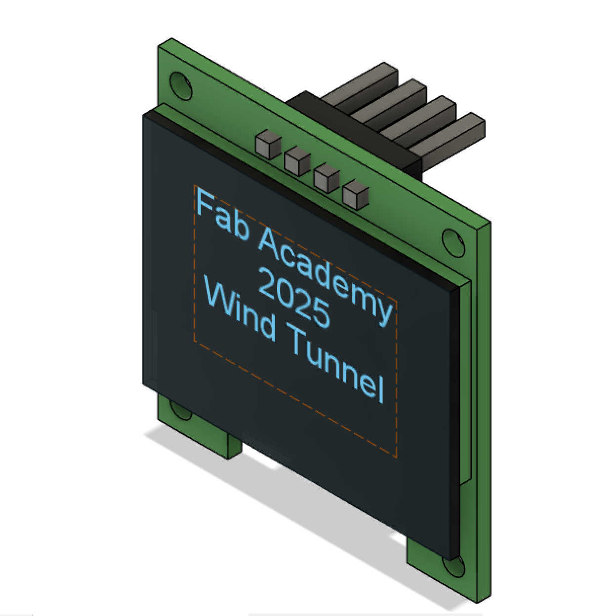
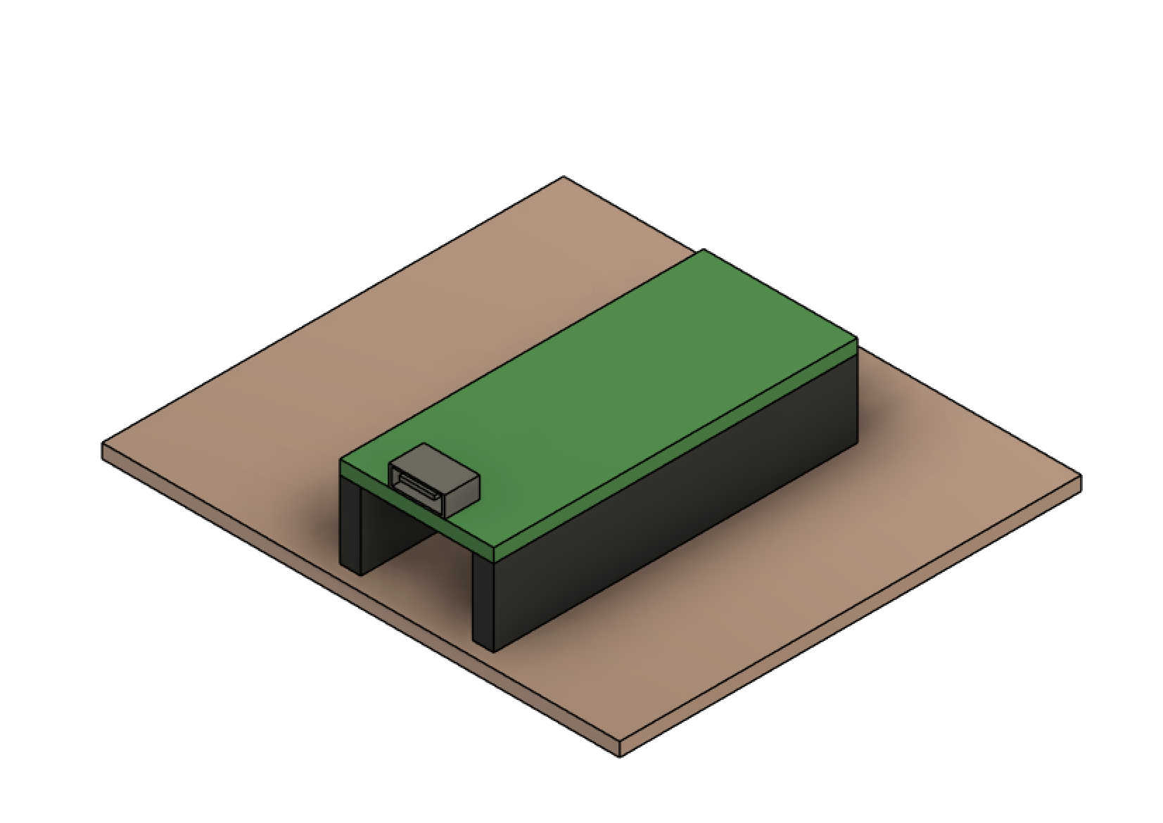
To fit all the electronics and to have a completed CAD with all the components I needed to create a CAD of the eclectics. The electronics will be housed in such away that minimal wirers will be seen. There will be some exception as the wiring of the fan will need to run to the pcb. All that being said. I created the first component the OLED display. To do this I just took measurements of the OLED display and created a mockup. This will help create the box opening so that the display can be fitted.
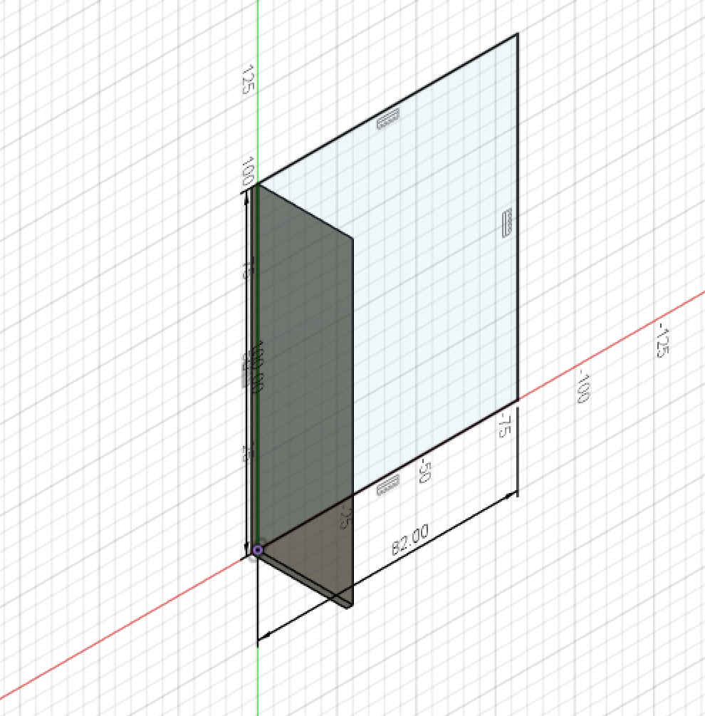
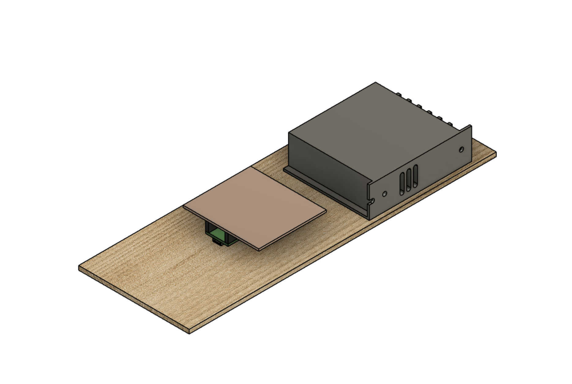
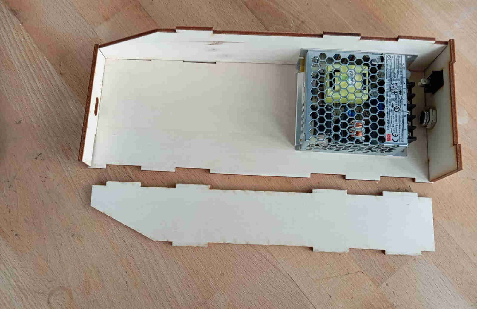
Lets look at creating a the power supply, looking over the data sheet we can get all information on how big the component is and where the location of the holes are. The holes are important as they let you bolt the power supply down. The basic dimensions of the power supply are 100mm X 80mm X 30mm (Length, Width, Height). Here is the result of the mocked up LRS-35-12 power supply box.
I could have added more detail, but the parts are just to help later with assembling the tunnel and making the final parts so that the everything is nicely packaged
in a presentable way. This will also help in creating instructions on how to assemble the tunnel and it's electronics. Four more parts are missing for the full electrical
assembly using CAD. The 10kg load cell,
ON OFF switch,
PCB with micro-controller
and the Humidifier module, which is the only product that was bought on amazon.
Now that we have the power supply mocked up, the box that will house the PCB with micro-controller can be designed. For the PCB board
the pins and and wiring should have enough room to be laid out in way that over heating or can be avoided. We will need something to hold the PCB in place. As I did not
think about this when creating the PCB, holes will be carefully placed and drilled by hand.
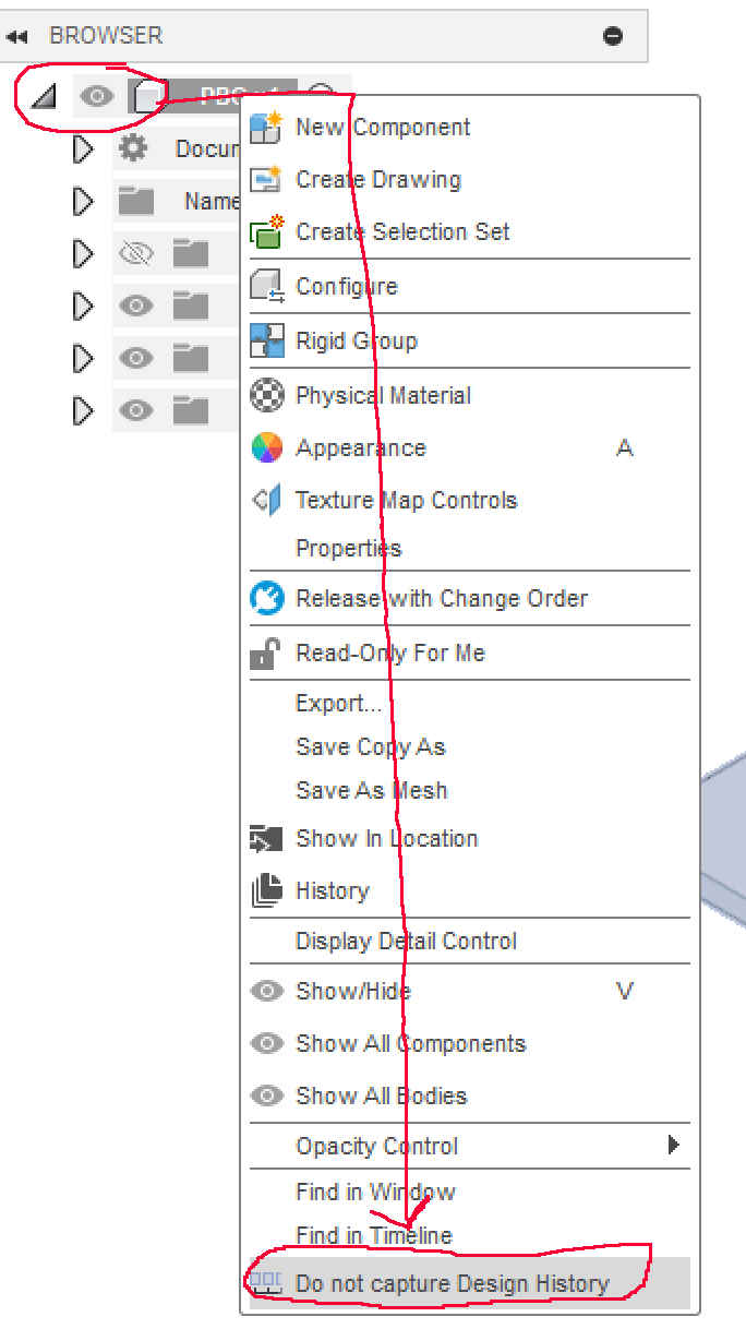
Having created all the mockups that need to housed in a safe environment. We can place the parts on a new drawing. To to this you will need to turn of capture history.
To this this you will need to right click on the Brower tree and go down to the bottom of the pop up menu and select Do not capture History.
Adding parts
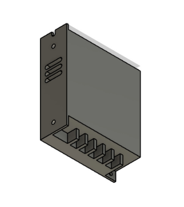
Now all that is left is to click, Drag-and-drop placing the parts where they need to be located. Placing he power supply box and the PCB we can now start with
sketching the bottom of the housing. The dimensions of the bottom board are 300mm X 108mm X 4mm (Length, width, thickness).
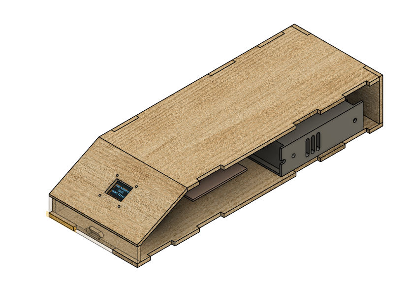
Having add the PCB and the power supply and having stared a new sketch with the measurements mentioned above, the result should look like this after adding the physical properties
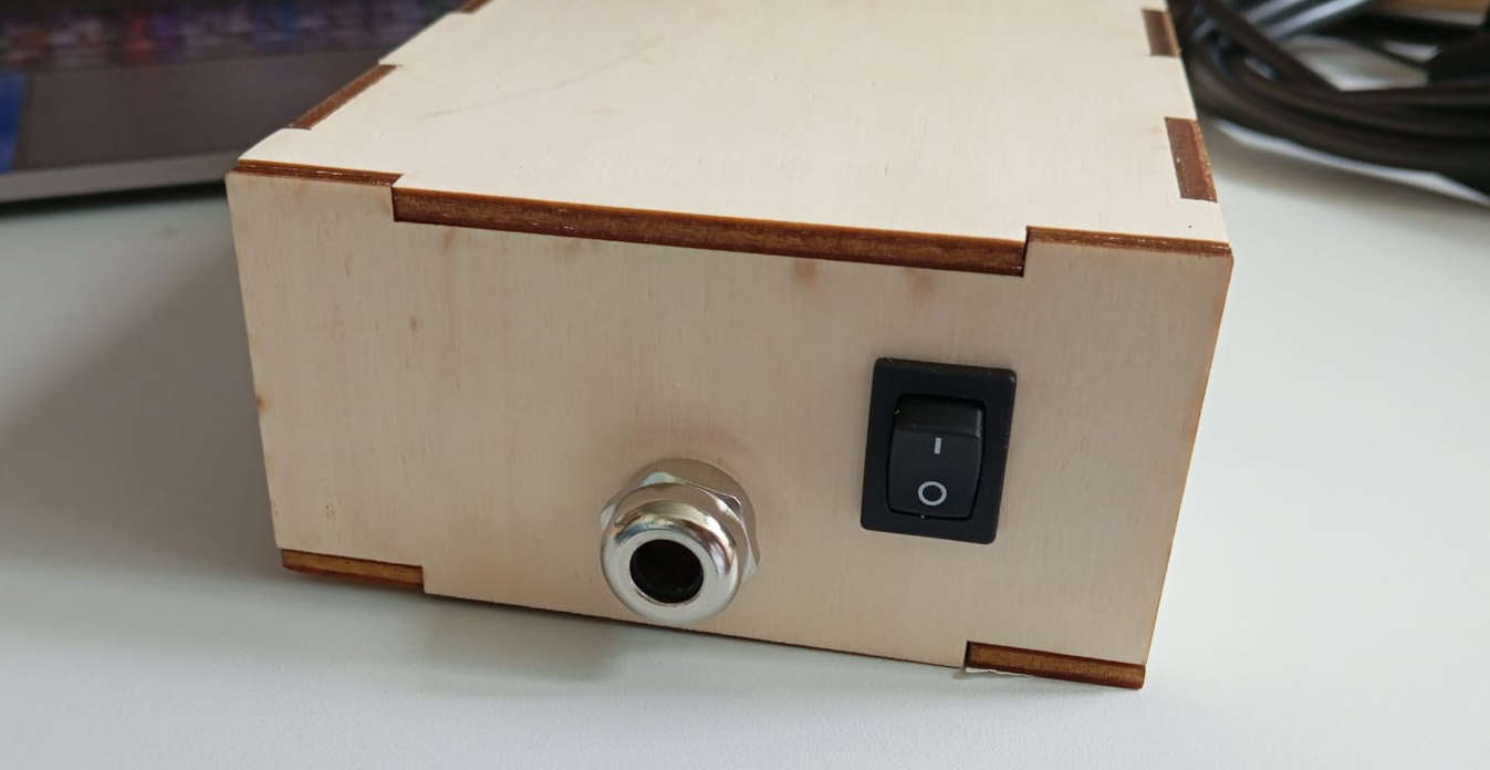
Having added all the components to the power housing, all the was left was a hole of the power cable to enter from and a switch to tune the power on.
For the switch with a 19mm X 13mm rectangular hole and for the power cable with fastener to hols the cable in place a 15mm diameter hole
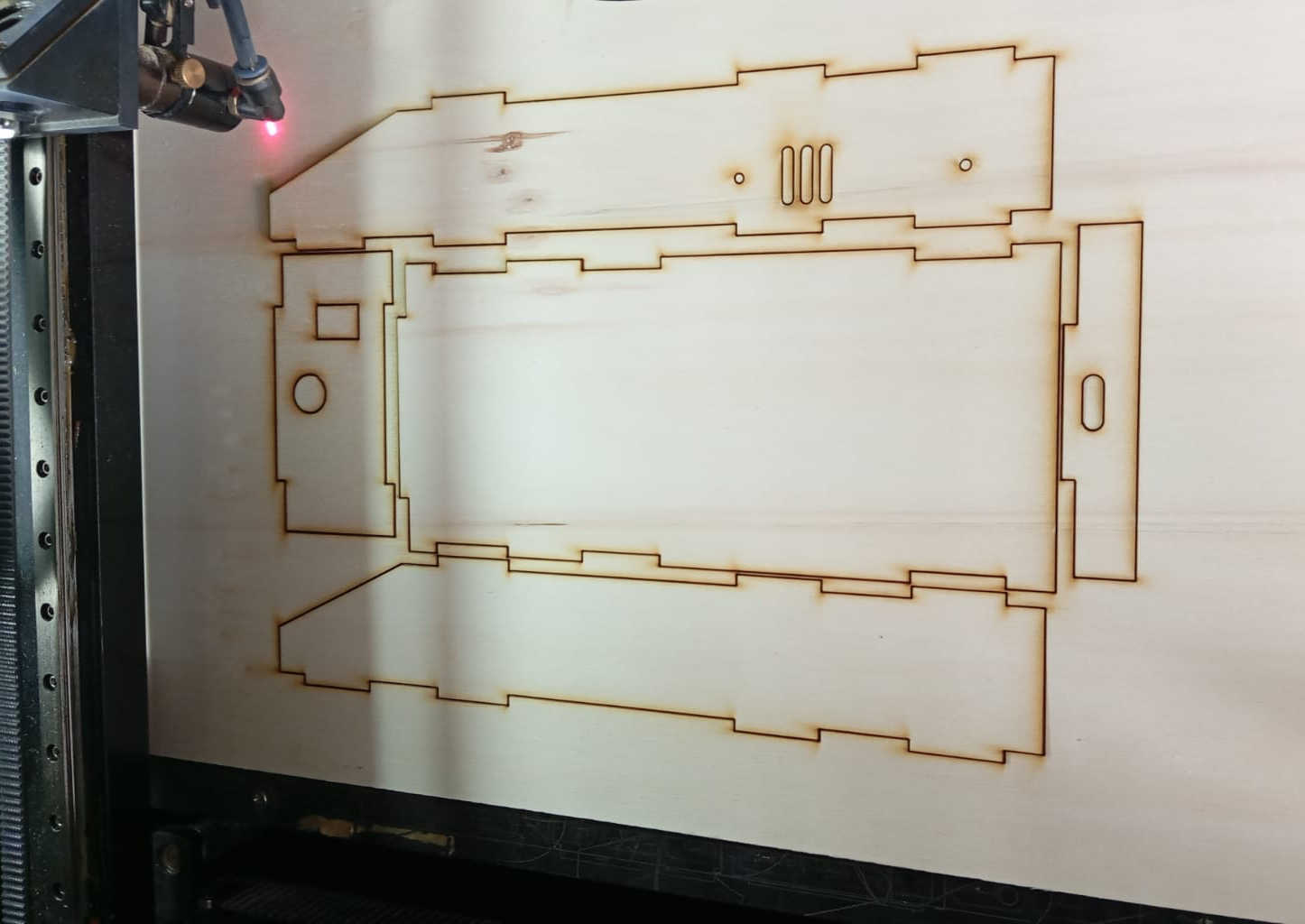
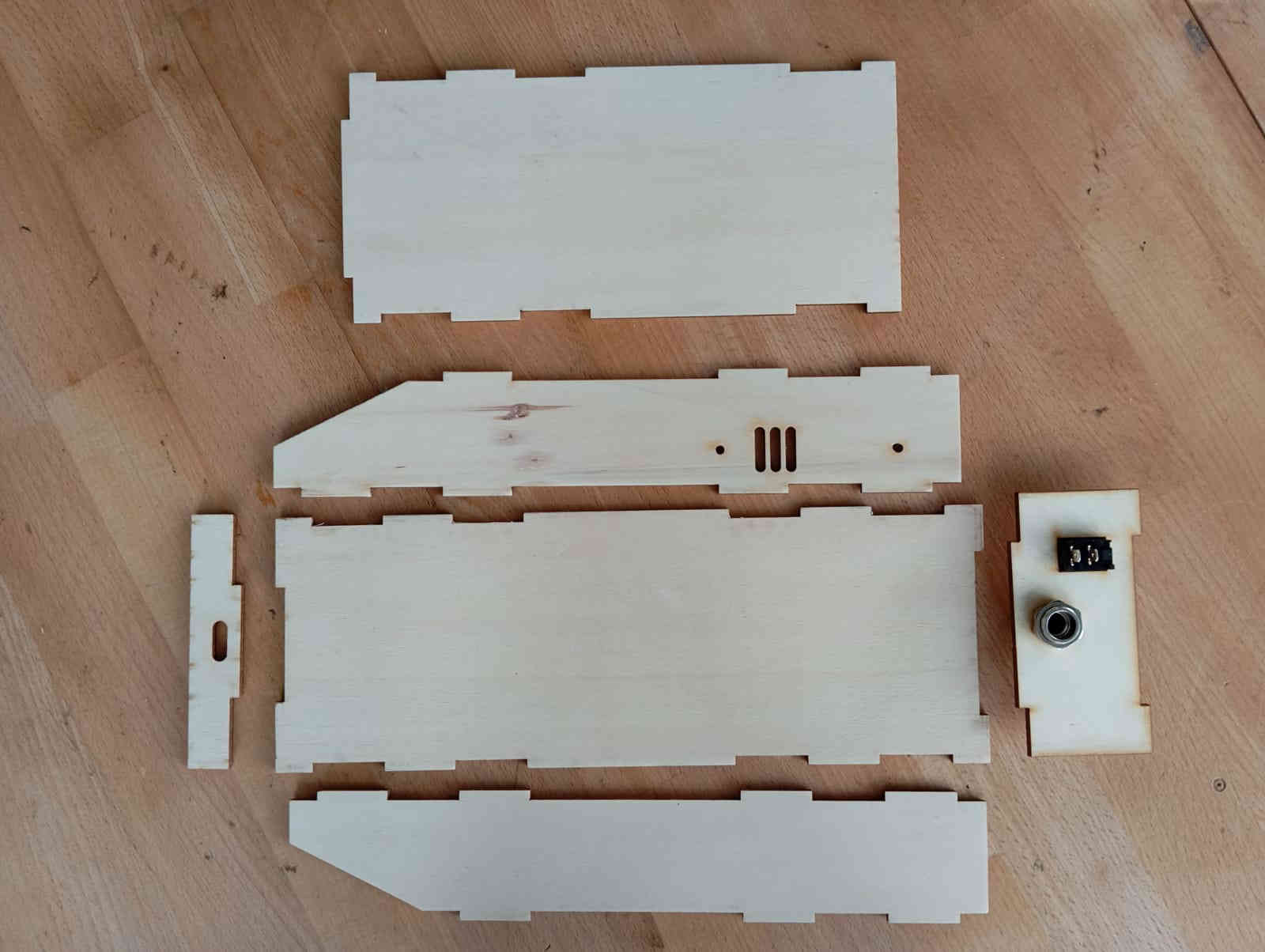
is needed. Next it was time to go ahead and laser cut the parts. To make sure that everything fitted as in the design, only the bottom and sides were cut using the laser
cutter. You may have noticed that the display panel has no finger joins. The reason for that is this panel will be glued in place. As the angle calls
for some sanding or hand planing to get the angle just right to fit nicely. Ideally the power housing could be made out of sheet metal.
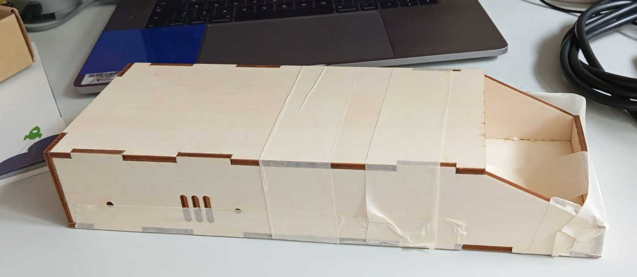
The sides and bottom panels will be glued with wood glue. As the Power housing is small and the big clamps in the lab are not really made of such small parts, painters
tape can be used. This technic I have used before when making picture frames, and works really well, even with 45° angled cuts. To access the power supply box the top lid
will be removable. This insures that if any changes need to be made or future upgrades can be wired in or repairs can be done.
Hero shots of the build
Starting with wiring
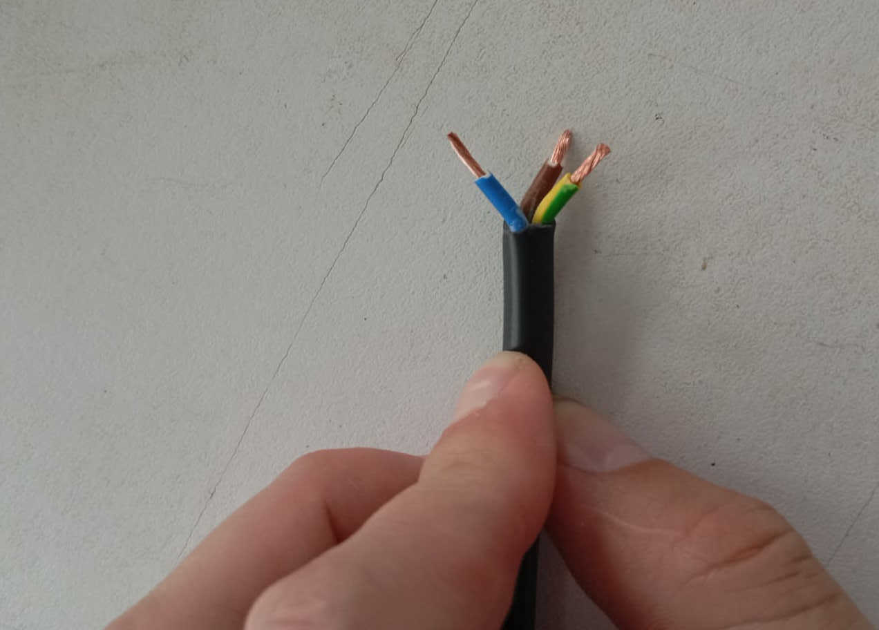
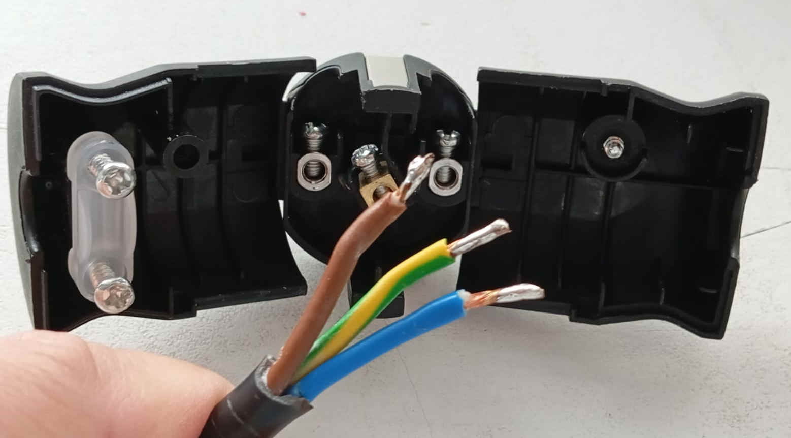
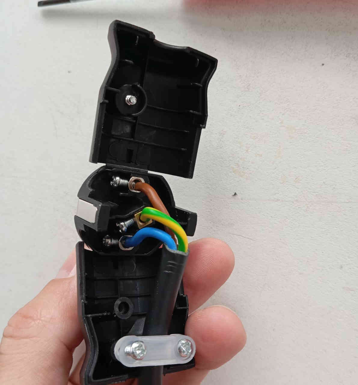
As the wind tunnel has a power supply box, it was time to go and buy a 3 vain cable and a plug for the outlet. The Cable bought at the local home improvement store, the cable has a length of 2 meters 50. The plug was bought as well at the home improvement store. The first thing that needed to be done was to strip the wire and tin the wire ends. This helps the screw later to hold on tightly and keeps the cooper wires from ripping. Do this to both sides as it insures a good result with the connectivity as well. In oder to connect the wire correctly, the Green & Yellow is ground and the Blue wire is either negative or positive, the same goes for the Brown wire.
Power supply
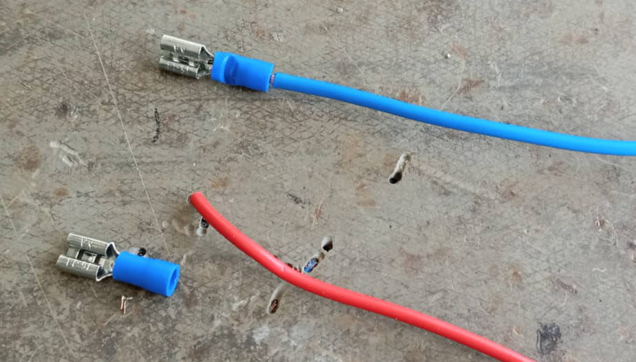
Next the switch was pressed into place. Looking at the connections that are needed to turn the power ON or OFF an extra wire is needed. At this point were the connections are being made, the color of the wires play a role. To not mix things up, I used colors that matched. Red & brown for the Positive and Blue for the negative. As there is switch I needed an extra wire with a Female Crimp Connector which went on one side of the wire. This end goes to the power switch. The Brown wire on the cable to the wall plug also needs one Crimp Connection that goes to the the switch.
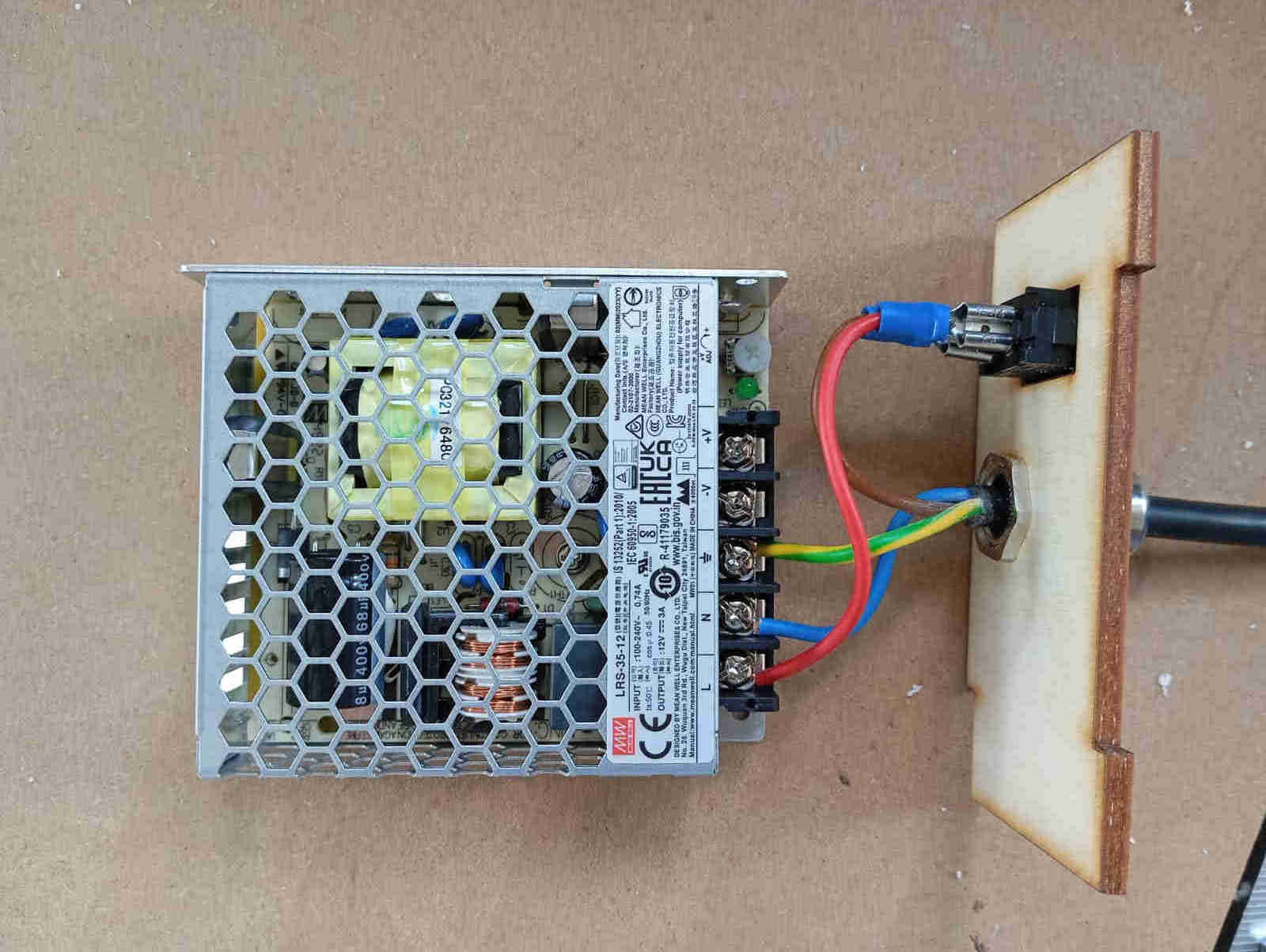
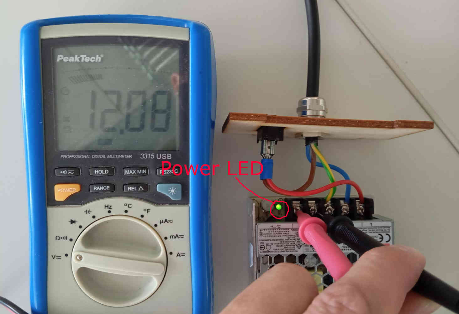
For the power supple you should look a that data-sheet for the (LRS-35-15), if you are unsure of what you are doing. But just in case Green & Yellow is the ground wire, Brown wire is the L connection and the Blue wire is the N connection on the power supply. If everything is connected correctly the out put should read 12 volts when using a multimeter. Plugging in the connector and flipping the switch on you should notice a small Power LED turn on. The result if everything is done correctly should look something like in the image below.
LEDS strip
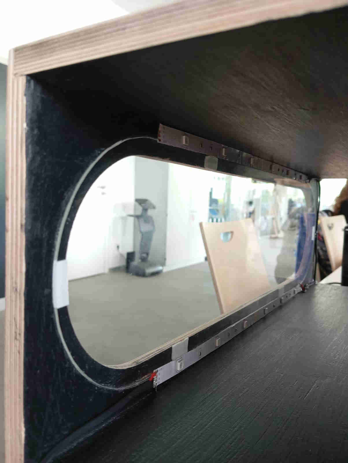
Unfortunately I did not thing about the voltage needed to power certain LEDs. Lesson learned is that there are many different types of LED strips that can have multiple colors and controls. I could have added LEDs that would have allowed me to control when they are on or off. But as the LED on the PCB wont be visible when it is in the completed Power housing. It made since to have them connected to the PCB. So that when the power is on the the LEDs light up. This serves two different functions. One it lets us know that the PCB works and nothing us blown. The second function allows us to have a better view in the tunnel. Once the LED strips had the wires soldered to them, they could be placed in the tunnel. The LED strips are located just below the window and just above. Lighting up the whole testing sections of the Tunnel. As the tunnel is painted the LED strip glued itself very well in place.
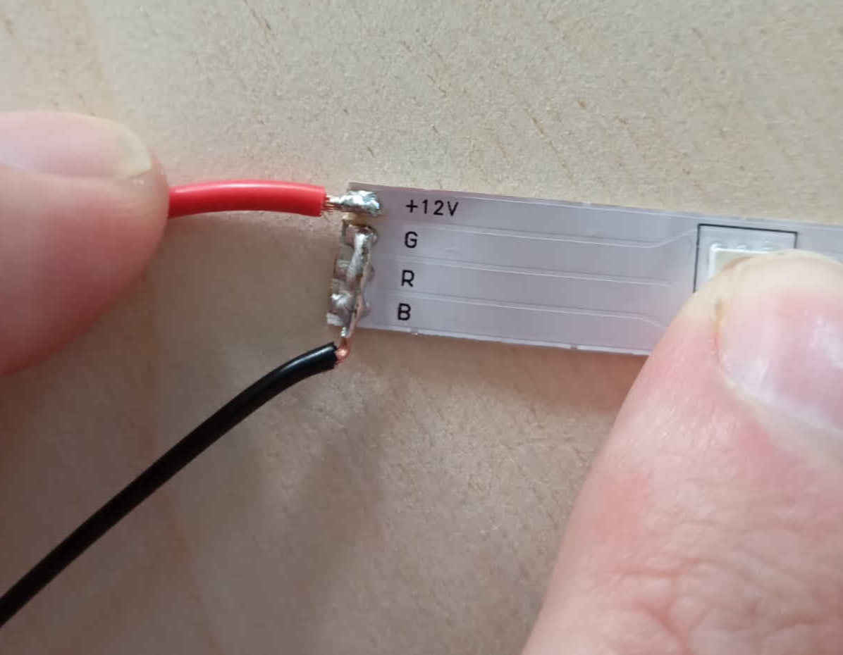
You will notice that the LED strips negative wire joins with GRB, this is because only one color is needed. This is not standard practice, but in our case this works out to what we need to light up the tunnel so that we can what is happening on the inside. As I mentioned above there are two strips of LEDs, meaning that ones strip is connected to the other with wires. Before soldering make sure that you have the right amount of wire length. Since this will be in the tunnel we want the wires to stay as close as possible to the walks of the tunnel. Ideally there would be a channel to let the LED strip hide in. This will most likely happen on the next version of the testing section. Next a hole was drilled for the wire to exist the tunnel. This hole should be just a tiny bit bigger than the wires. Once the wire is pulled through use some hot glue to clos off the hole.
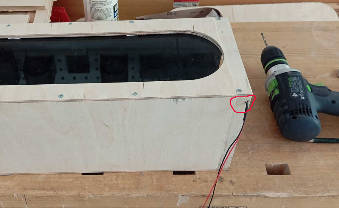
Note that the hole was drilled as close as posable to the end off the tunnel. A small channel will also be added to keep the wires form being pinched be the outlet mount fo the Fan.
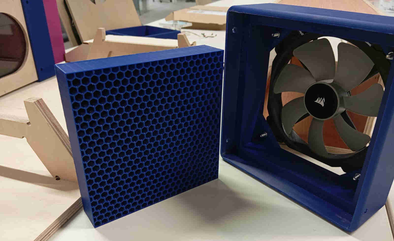
Adding the fan
After the leds were installed it was time to fit the fan to the end of the testing section. To make sure that there would be laminar flow a second air strainer got added. This was an idea to help avoid back flow. The fan is bolted on with four M4 bolts by 30mm length.
Integrating the Water vapour
After trying out the one Humidifier module . It was very obvious that more than one will be needed. To trigger these a single button with two functions is used. One press let the system run constantly and a second press will let the module turn "ON" and "OFF" in time intervals. After having talked to with instructor about different solutions we came to the conclusion that we needed to test and see if the module was really using 1amp on 5Volts. Having hooked everything up to a lab power supply we found that it only pulled 0.018 amps. This means that in really life I could hook up all four modules to the power supply and let it run off my PCB. Ahmed came back with a relay, that would allow the the modules to be tuned "ON" and "OFF" with a command from the PCB. over the IDE Serial Monitor. To try this out, the simple blink code from the examples was used. Replacing the code line Built_in_LED with GPO1 pin.
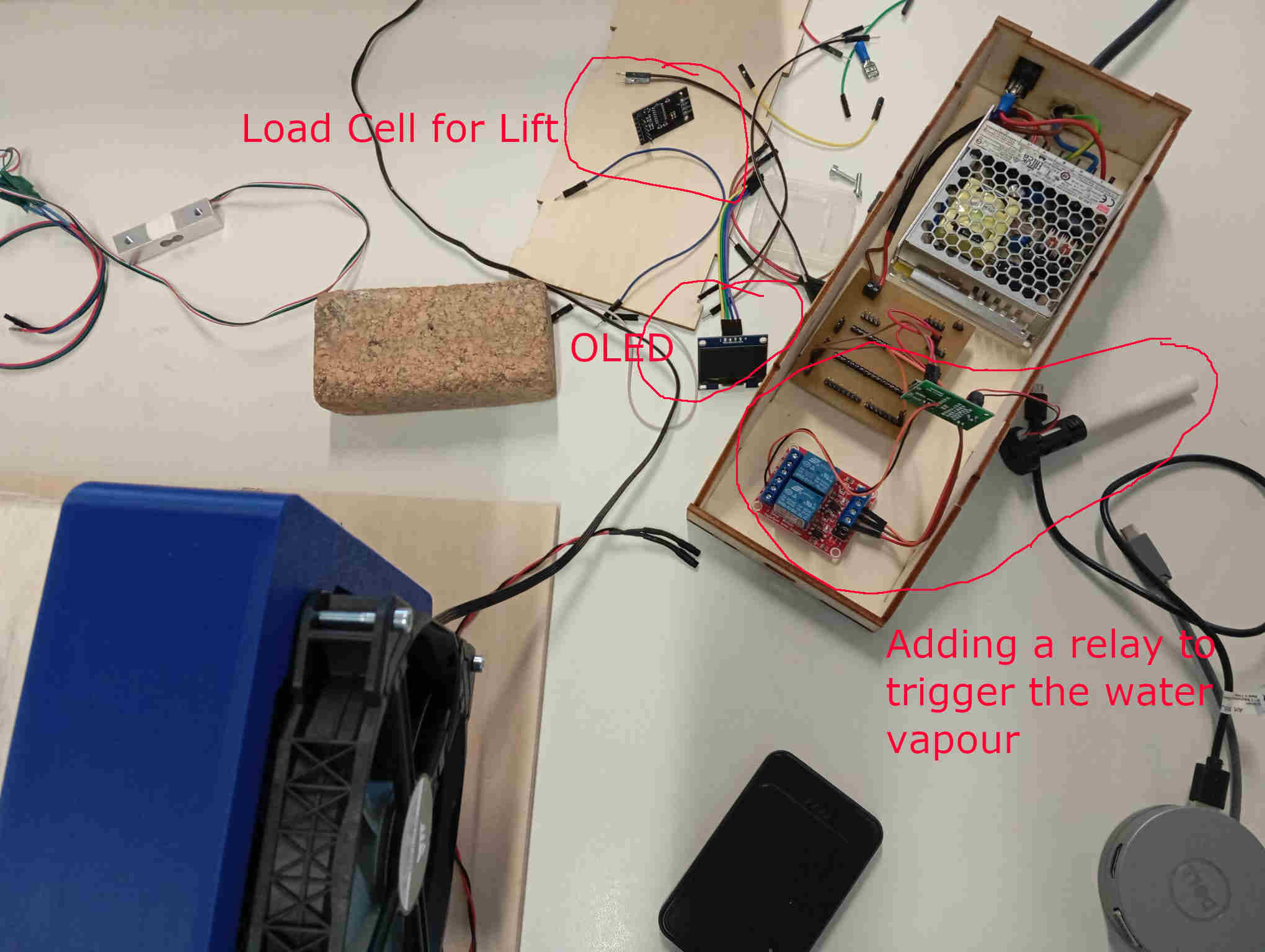
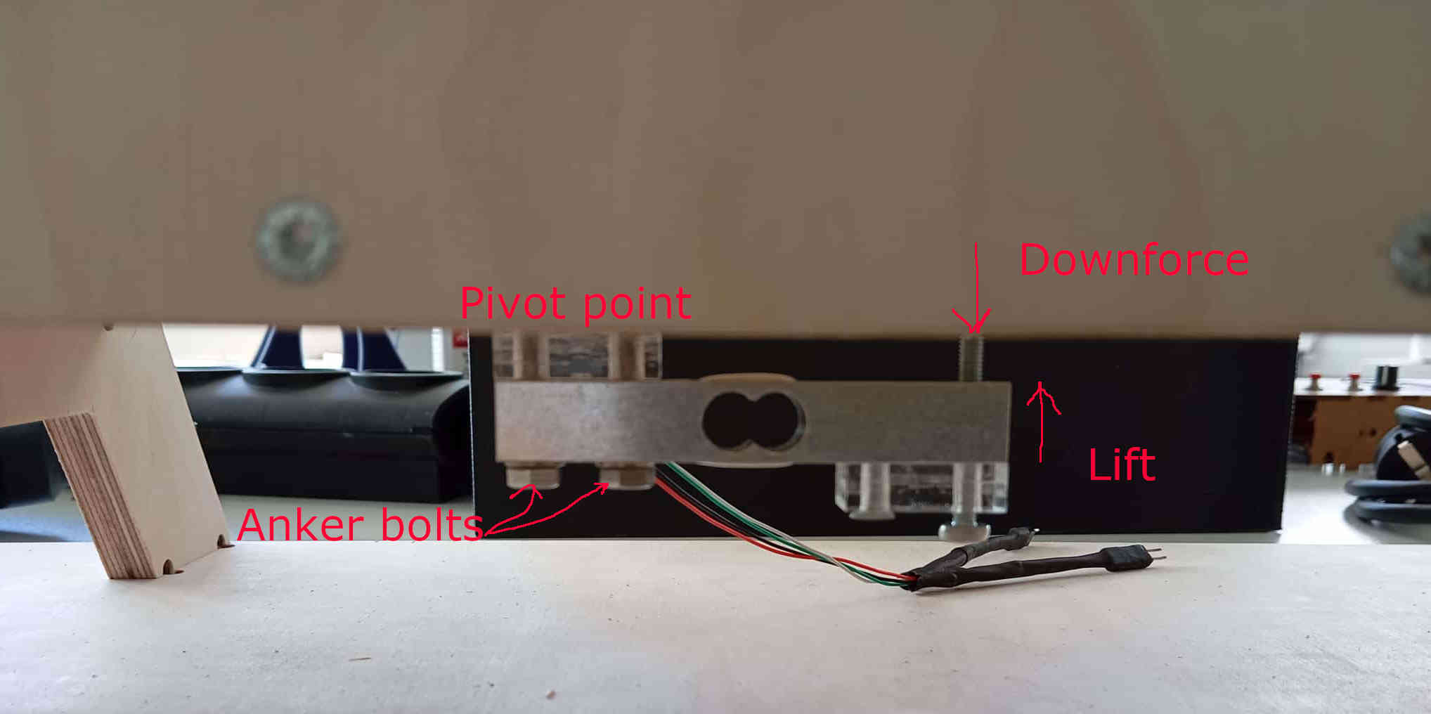
Having had success with the one module and the relay, it was time to address the load cell. For the time being only Lift & down force will looked at. In the future I will add a load cell that can read both lift and drag. The load cell will be mounted under the tunnel, with a rode going through the bottom of the tunnel, where a Wing or model of some sort can be mounted. As the load cell will not be taking extreme forces. The threads can be cut in the plywood. I have done this before, the threads will hold up to about 2kg depending on the wood. Glue can also be used to help lock the the two bolts in.
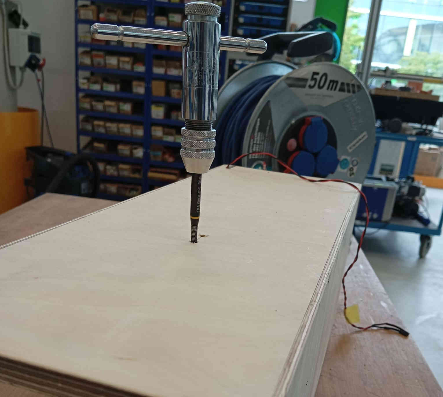
The load cell is placed in the middle of the tunnel and the holes are marked out and bored. As each load cell can be different make sure to source the the right drill size, as this will matter when cutting the threads. For this load cell I used a 4.2mm drill bit, so that the threads can be cut properly. In wood you could also use 4mm drill bit, but in other materials stick to the correct sizes as you do not what to snap the Tapping tool. Testing the load cell is simple as a working code can be found at the end of Input Devices. Als tha dxf file is provided to make your own scale if you are just exploring options.
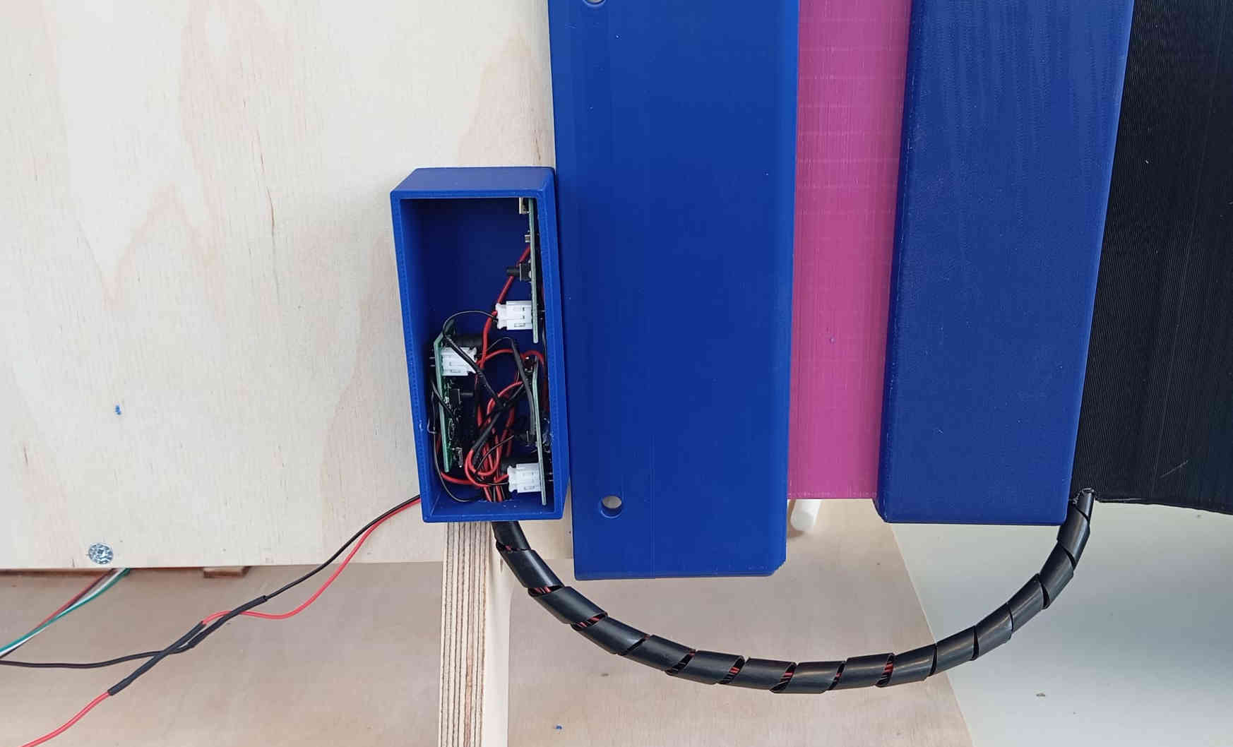
On the back of the tunnel a small Electrical junction box hides the module that connect to the piezos which vaporize water to
create the a smoke like effect. The wires feed through the bottom side of the Air-Intake. The wires have been
lengthen, as the ordinal wires were only 60mm long. Having her wires at different lengths also allows the modules piezos to
be moved to different positions on the air-strainer.
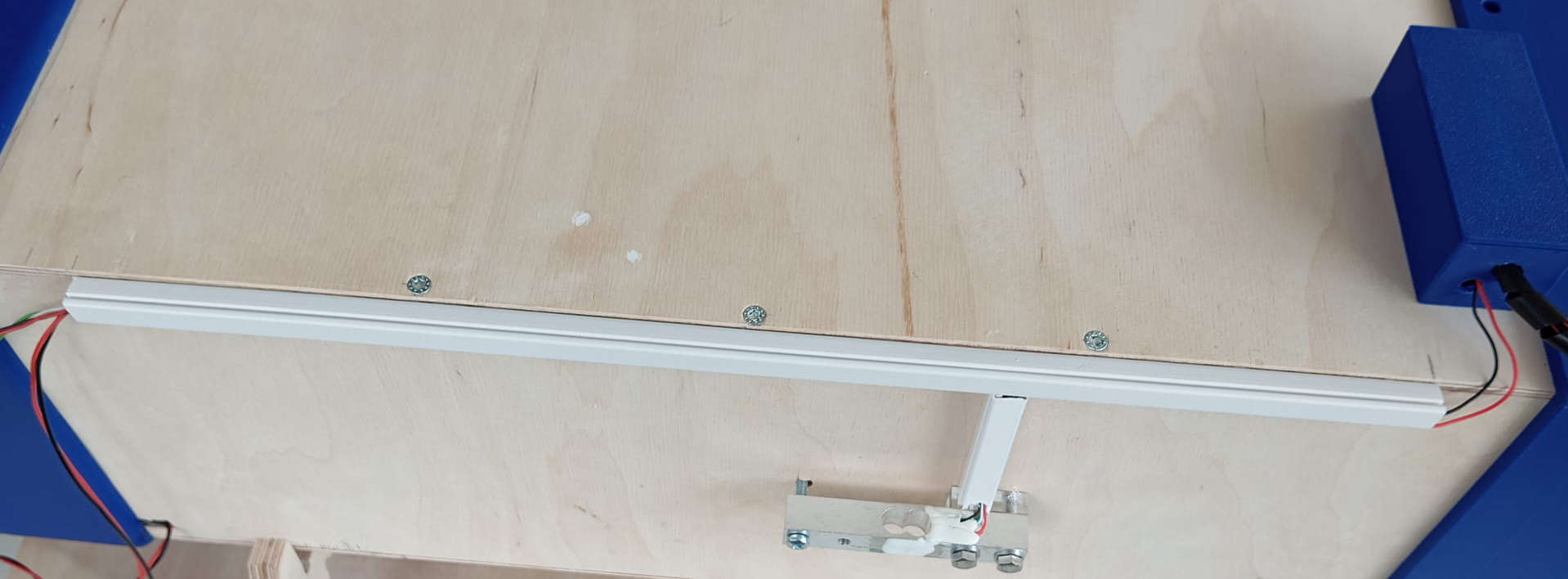
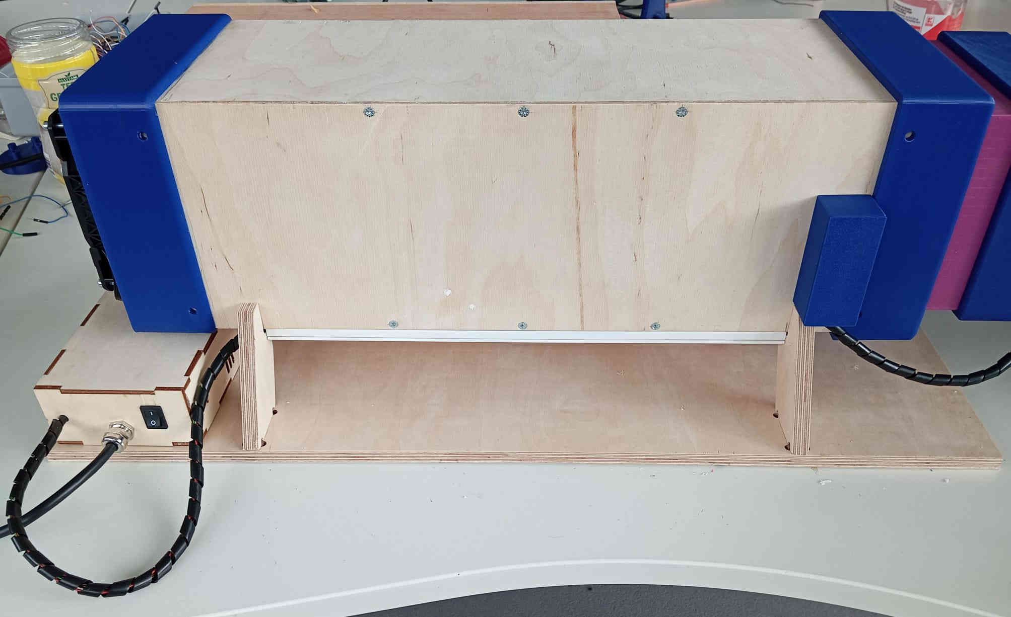
To keep wires from the load cell as well as the wires from the module U-channel was attached to keep the wires safe and easy to manage. The
U-Channel was bought at the local home improvement store and cost: 2.99 Euros. The cable spiral cost: 4.99 Euros for 5 meters
which can be bought at the local home improve store as well. The images below show how all the wires are organized.
Next we need to connect all the switches, here we do the same connect all the negatives and positives. Once the signal is sent from the micro-controller to the relay, all three modules should turn on and off on command. If not check if there in any bridging between the solder points and or wires crossing each other. This is a problem that I ran into. Letting me resolder all wires, making sure that each time one board was connected and working, than adding the next board, till all were working as they should. The modules should have a each a blue LED that turns on when the micro-controller sends out the signal to open the relay. Here is the code to test the modules are working correctly. The code is very basic and acts more like a switch, letting the module use both functions that come with the module.
	// Testing the function of the modules and the relay acting like a switch.
	void setup() {
	  // initialize digital pin GPO as an output.
	  pinMode(0, OUTPUT);
	}

	// the loop function runs over and over again forever
	void loop() {
	  digitalWrite(0, HIGH);  // closes the relay on (HIGH is the voltage level)
	  delay(100);                      // wait for a millie second
	  digitalWrite(0, LOW);   // closes the relay off by making the voltage LOW
	  delay(5000);                      // wait for a second
	}
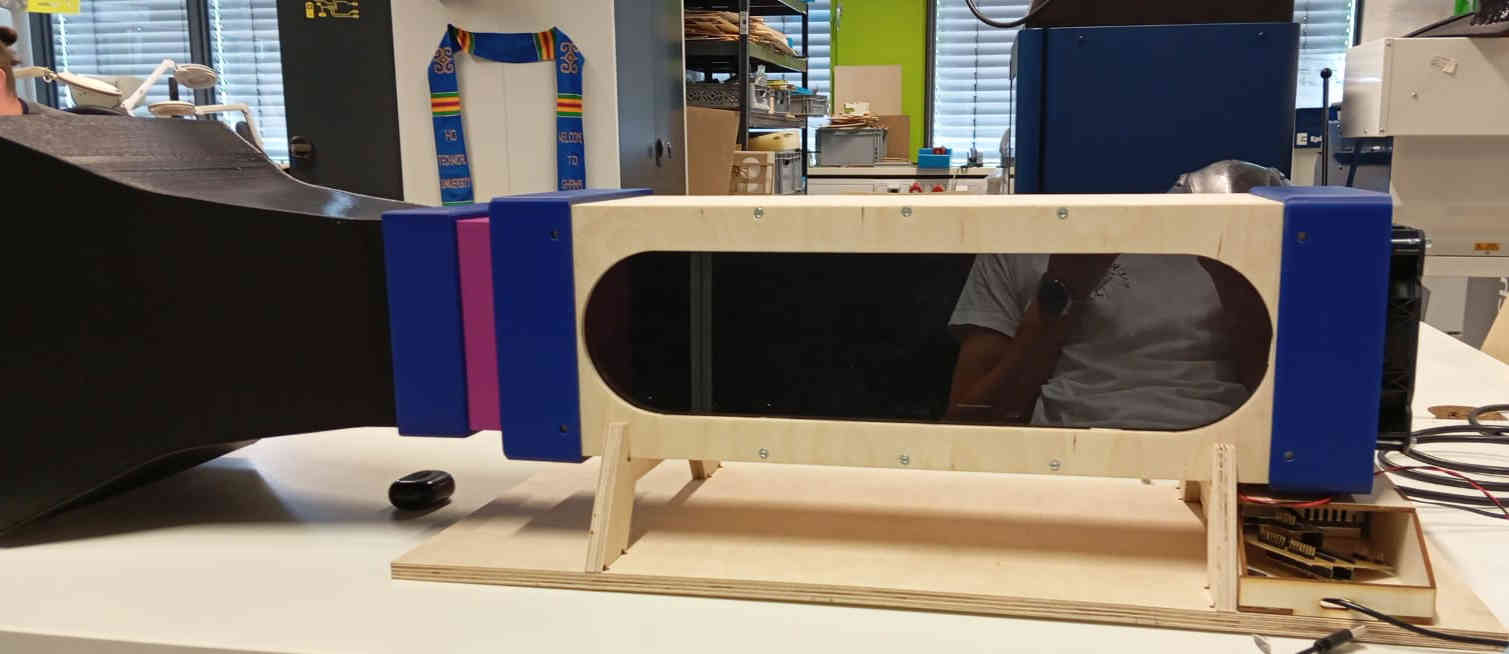
The design
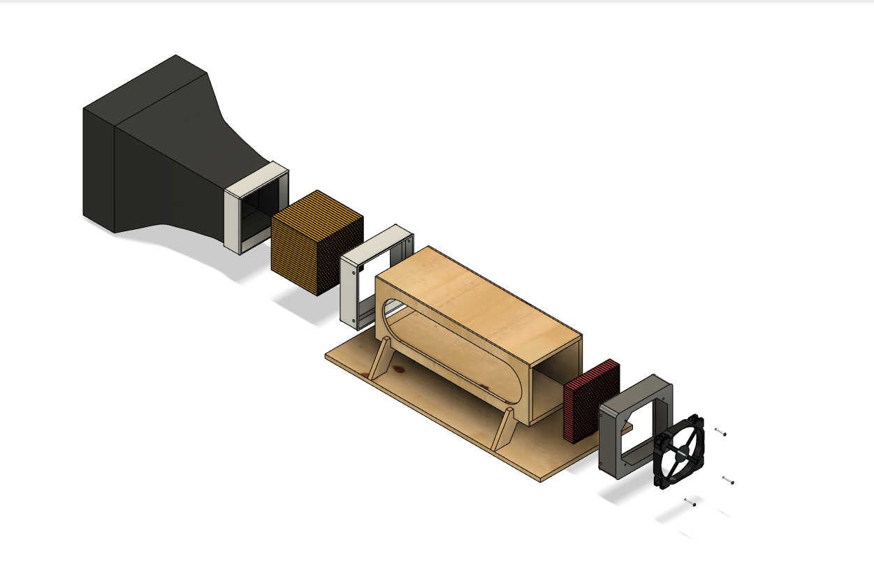
The full design of the tunnel looks more complex than it really is. The air strainer is really the only complex part, as the hexagons were a pain to get allied as the CAD software took a long time repeat the pattern. The Intake could be make of a more friendly material, like wood or cardboard. It would give the intake a smoother surface, as the current one is rather rough from the the 3D printing. In the future this part will be replaced with either material mentioned. All the connection parts of this build could have also been made of nicer materials, reducing the use of the plastic. Even if the plastic being used is PLA which is Bio-plastic. The image below shows how the tunnel is assembled from the Intake to the Pc Fan at the end.
To download
The design is free to download and use under the following: Wind Tunnel by Lysander Trapp is licensed under CC BY-NC-SA 4.0