09 assignment INPUT Devices
What is an input device? It si a piece of hardware that can collect data, which it will send to a computer. This allows
the user to process and interact with the input information. The computer than converts this information to information
so that the user can understand. This is relies on what the device is capable of doing. Any sensor many process a wide
range of input information, it all depends on the type of sensor you are using. So this week we will continue on the
adventure of electronics. For this I will use the PCB board that I made in lastweeks assignment 8.
Which is also the main PBC that I will be using to control parts of wind tunnel for my final project.
Last week I make this board PCB board with several connection, under those we have a load sensor. Later on I do want to
make my own sensor for my final project. Till than I will be using a 10Kg sensor with the HX711 scale module. At first
I was thinking of integrating the mod directly onto the board, but I was advised that this module is so cheap we can
just buy it. Which saved me form figuring out how to designing one. What we did do in this case is pay close attention
to the wiring that comes with the HX711 module. This makes it easy to hook up the module to the PCB. We should have
four connections, GND, DT, SCK and VCC in that oder. Looking over the the PCB boards Schematics found in last
weeks assignment 8 Electrical Production.
As mentioned I am using scaling input devices from joy-it called theHX711 here is that datasheet for the moduele.
Looking of the data-sheet we are looking for how to solder the wire to the module at are attached to the sensor. In the
end I just ended up using google to find the out what wire goes where. The module itself is just a amplifier to increase the input
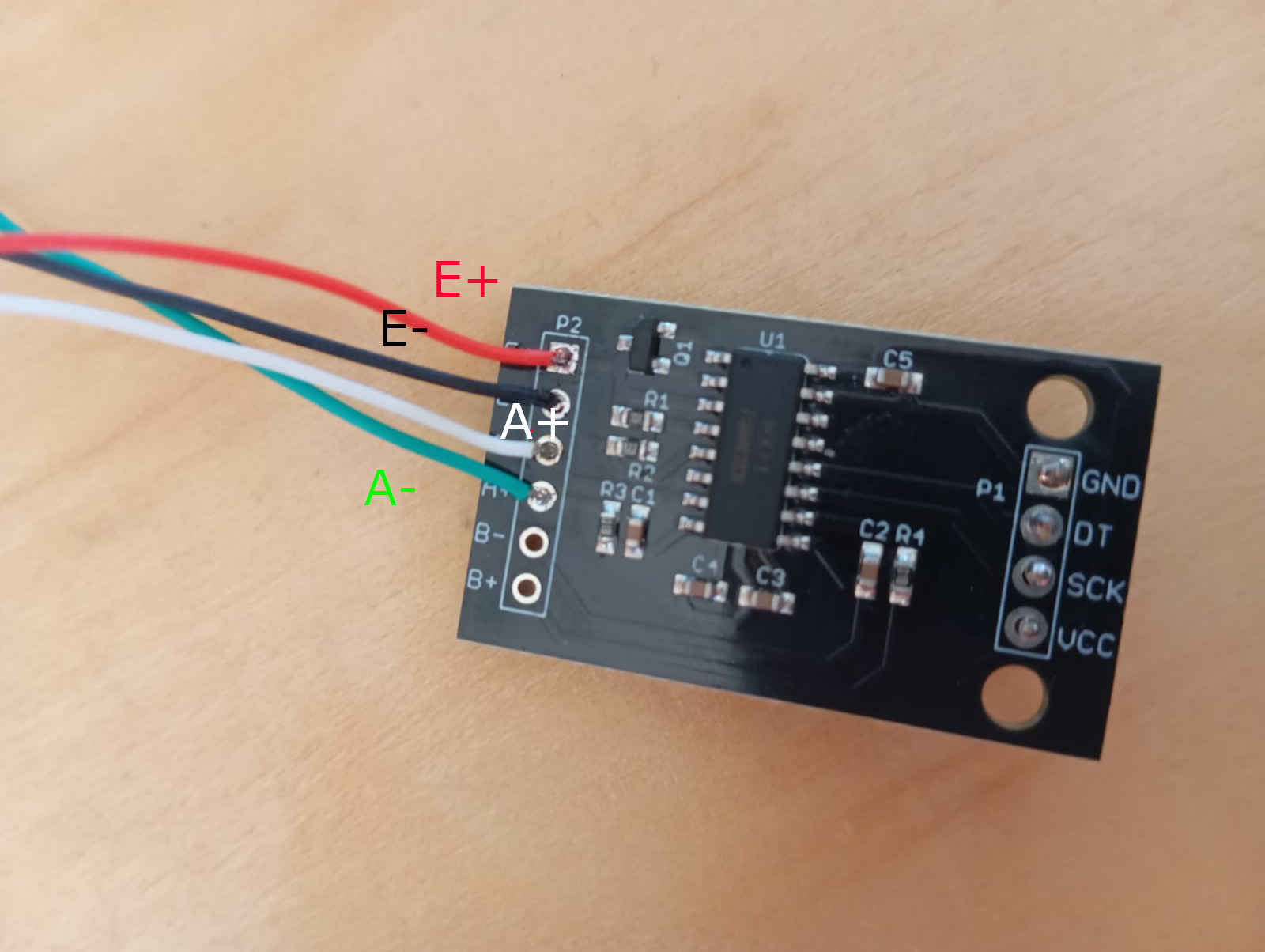
where a resistances gets changed through strain, bending of the beam. We have the connection E+, E-, A-, A+, B+,and B-.
After more digging I found out that the E+ and E- stand for excitation voltage. Here we connect the Red wire to E+ and
the Black wire (GND) to E-. What do the other letters stand? You guessed it back to reading the data-sheet. Here I found out that
there are channels. A+ and A- are for high precision, 128x or 64x gain and the B+ and B- channels are for lower precision, fixed 32x gain.
So I went with the high precision channels.
How to install the HX711 module
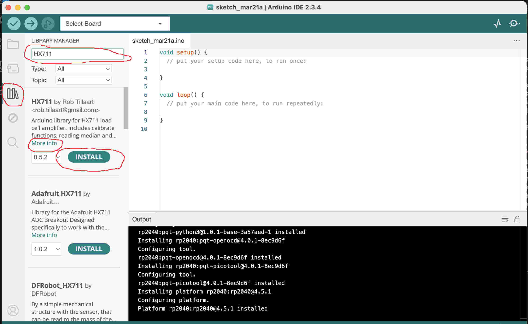
Next, we need to figure out how to use the module, as the IDE and the PCB won’t know how to process the information without having the required library installed in the IDE software. To do this, open the IDE and look for a symbol that looks like books in the sidebar menu. Once again, look for the more information link to make sure that the library is compatible with the HX711 you have, click install and the library will be added to the IDE.
Getting started with writing a code that will work with the PCB board. Looking over the boards Schematics, checking which pins
were selected in when designing the PCB. Pin GP18 for Data and GP19 for SCK (clock). VCC is hooked up to 5volts GND is connected
to common ground. Having written this down we now need to know in what computer LANGUAGE we want to write the code in. I personally
like C++ but you can also write your code in Python. I have read that python is a good language to write code in for sensors.
A crucial piece of code we need is #include "HX711.h". This line is necessary because it includes the library required
for interpreting data from the HX711 module. While writing this, I realized that I cannot simply hook up this sensor and expect it to work.
Since this is a scale, calibration is necessary to ensure accurate data output. Without proper calibration, the measurements
will be inaccurate. After further research I found that most people seems to use the baud rate of 115200 for scales.
A baud rate is the rate at which information is sent. A baud rate that is typically used is 9600. This rate
provides a good balance between speed and reliability, especially in older communication systems. For example the
Arduino board with a super sonic sensor.
	#include "HX711.h" // choosing the library or libraries

	// defining my pins
	const int Data_out_PIN = 18;
	const int Clock_SCK_Pin = 19;
	const int Weight_Calibration = 5000;// here you want to use ideally use half of the max weight
	HX711 scale;

	void setup() {
	  Serial.begin(57600);
	  scale.begin(Data_out_PIN, Clock_SCK_Pin);
	  scale.set_scale();
	  Serial.tare();
	  Serial.println("Calibration");
	  Serial.println("place Known weight on scale");
	  delay(5000);
	  float x = scale.get_units(10);
	  x = x / Weight_Calibration;
	  scale.set_scale(x);
	  Serial.println("Calibration finished.....");
	  delay(3000);
	}

	void loop() {
	  if (scale.is_ready()){
		float reading = scale.get_units(10);
		Serial.println("HX711 reading:");
		Serial.println(reading);
	  }
	}
Uploading the Code
After writing the code and finding all my errors/bugs and fixing them. We want to look connect the the HX711 module to the PCB. Looking over the pin setup on the PBC and making sure that everthing is orianited the right way around, connect the the module. I ran into the next issue, that the scalling sensor was getting no data input. only reading that was getting recived was that it was measuring 0.0 Kg. The next thing I checked were all my connections, first visually than with the multimeter making sure that none of the connections were having issues.
Check List
Here, I noticed that the red and green wires got mixed up. Time to undo the soldered wires and solder them correctly.
Mistakes like this can be avoided, as this shows that the internet is not always correct. It took a very close look
at the data-sheet to even notice that this mistake had taken place. The lesson learned here is that reading a data-sheet
a little more attentively can be beneficial in the long run. After multiple tests and running different codes, the load
sensor did not return any data. The PCB was checked multiple times without finding the issue at hand. We then tried running
the same code using an Arduino board and found that the HX711 module is faulty. A second problem that we ran into was the
we could not find the wire2. The first thing that came to mind was that we had somehow mixed up the pins. Looking over that
Data-sheet of the Rassberry Pi Pico W again, even triple checking, as it turns out this was all correct.
Not really understanding why the HX711 was not being detected, it was time to try the default wire pins for I2C. Even here
the module was not detected. This lead to trying out serval different codes and libraries, none of which seemed detect the
module. The only solution was to try another I2C module. After a long search we ended up using another I2C board to see if
either the Pico had a defect. This is were it got confusing. knowing that the pins we had used where the right ones, checking
the wires we now had hooked up were also placed correctly the module was still not being detected. This drove us down a rabbit
hole of issues. Why was this not working?
Not knowing why wire2 was not working got another Pico and found the same issue. Wire2 was not working with any of the codes
we tried. So everything was unplugged and hooked up to the default wire. This again worked with out much of an issue and the
default pins were detected. After a weekend and a long Monday it was time to say that that even though the issue with the
pins was weird. But okay, lets hook up the HX711 to the default pins. Nothing worked. Even holding the Reboot button on the
Rassberry Pi Pico W did not nothing to detect the HX711 amplifier module. The conclusion is that Module has a defect and we
will oder a new one. In the mean time I did some asking around and Frauke Waßmut
has a setup with a load sensor I could use to check if I can get a reading.
Down below you will find two sets of code. One for the detection of the module and one the wire2. These two codes will help you find out wether
the issue is with the micro controller or with module that you are using. Below that I will also have check list that you can do with a
multimeter, this will show if all the right values are there.
Code for checking if the HX711 is available
				#include "HX711.h"

// HX711 circuit wiring
const int LOADCELL_DOUT_PIN = 18;
const int LOADCELL_SCK_PIN = 19;

HX711 scale;

void setup() {
  Serial.begin(57600);
  scale.begin(LOADCELL_DOUT_PIN, LOADCELL_SCK_PIN);
}

void loop() {

  if (scale.is_ready()) {
    long reading = scale.read();
    Serial.print("HX711 reading: ");
    Serial.println(reading);
  } else {
    Serial.println("HX711 not found.");
  }

  delay(1000);

}
This code tests the detection of the Wire (I2C)
//wire detection code
#include "HX711.h"  // Include the HX711 library

// Define pins
const int Data_out_PIN = 18;
const int Clock_SCK_Pin = 19;
const int Weight_Calibration = 1000;  // Ideally, use half of the max weight measurable here 10KG

HX711 scale;  // Create an instance of HX711

void setup() {
    Serial.begin(115200);  // Set baud rate to 115200 for better performance
    Serial.println("Starting the scale HX711...");

    scale.begin(Data_out_PIN, Clock_SCK_Pin);
    scale.set_scale();  // Set an initial scale factor
    scale.tare();  // Tare the scale (reset to 0)

    Serial.println("Calibration: Place a known weight on the scale.");
    delay(5000);  // Wait for user to place weight

    float calibration_factor = scale.get_units(10) / Weight_Calibration;
    scale.set_scale(calibration_factor);

    Serial.println("Calibration finished...");
    Serial.print("Calibration Factor: ");
    Serial.println(calibration_factor);

    delay(9000);
}

void loop() {
    if (scale.is_ready()) {
        scale.power_up();  // Wake up HX711 if needed
        float reading = scale.get_units(10);
        Serial.print("HX711 Reading: ");
        Serial.println(reading);
        scale.power_down();  // Save power when idle
    } else {
        Serial.println("HX711 not ready...");
    }
    delay(1000);  // Read every second
}
check list with a multimeter HX711
(depending on how it is setup voltage)
Two things to try at this stage is another load cell or another HX711 chip.
Lets try another amplifier
Thanks to Frauke Waßmuth, who is lending me for the time being another HX711, gave me the chance to test if the Problem is with Pi pico or with the HX711 from joy-it.
The setup will be running off the a breadboard as this setup is part of a different project and needs to be returned in same condition it was lent to me. After some
back and forth and trying different setup and different micro-controller, we finial got a result. At the point I had to run to the class I teach. Next I will try to
get a reading with the old HX711 in case that this board is actually okay. Another thing to mention at this point is that I am not the only one having issues using
the Rassberry Pi pico W with the Arduino IDE. Many re-flash the board and use Python which works apparently better with the Rassberry.
Update, the problem is in fact the HX711 from joy_it. I recompiled the same code and it uploaded to the Pi Pico W without any other problems. Now I added the HX711
this did not work. Just in case I went and switched the wires around to make sure that I did not mix up the wires. This was not the case and the nothing changed.
As mentioned above I left things hooked up the main PCB and took a closer look with the multimeter. Here the findings were very interesting. For the voltage I got
5.0V which is correct as that was the voltage was being used. Next I checked the A- and A+ here I got a voltage reading that was a lot higher than it needed to be without
a load to be accurate the voltage reading here was 2.2 volts. Telling me that issues was the board.
The other issue i2C (wire1)
Trying to scan for the i2C wire was another problem that appeared. This took also took some time to understand what we were doing wrong. But
where there is a will, there is a way. Or at least some kind of solution. This was found after looking over at what could be causing the problem
with the IDE. Looking for the Arduino folder that contained the hardware information on mac was easy and eventually we left the mac-book for a PC windows
10 system. At this point most of you are cheering. Well this file was also not easy to locate on windows and we ended up switching back to a windows 10 system
that was not the latest. We did find the file that that we have been hunting for and could now look at the pin out of the hardware libraries. This also helped
to confirm that the right board was downloading, showing that hardware library is comparable with the Rassberry Pi Pico W.
After a lot of trail and error, looking for files the would allow us to change the pin setting and we found two solution, and the mistake that we kept
repeating. One way is the find the file with all the board information and edit the wire in the main library and saving this change. Which proved to be
harder to do as on mac we did not find the folder containing these files. The second way is to use the code Wire1.setSDA(18);
Wire1.setSCL(19); before Serial.begin. The next step is to make sure that all wire is changed to wire1 with in the code that you are using.
If this is not done you will run into the issues that it will not compile or find the i2C ports.
After many hours of headaches and back and forth so how everything was finally working. I still don't know why it did not work. finally some how the HX711
also worked! Yes the one and only chip that seemed to be dead. Here I can only say don't question it, if it is working. Now I am 3D printing myself parts to make
a fast and easy scale. This scale will only be used to calibrate for the time time being and to see how well it performance. It will not be the set that used
for the finial project. But maybe it will be used to check the weight of the objects that go into the tunnel of testing.
In the mean time here is a basic code to try out. You can either of to File > examples > HX711 Arduino library and try out any of those examples. As I am really
behind now because of the problems that have shown up with this part of the assignment I am going to use the code provided by the Arduino Library rather then try
to write my own code. This is in my option okay as I just need to get some kind of impression that something is working. Calibration will also have to be done
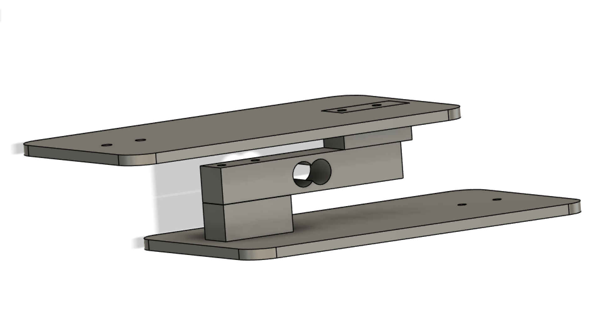
for this we will build a scale. I will include the 3D printed download files here for anyone to use for testing.
calibrate the scale
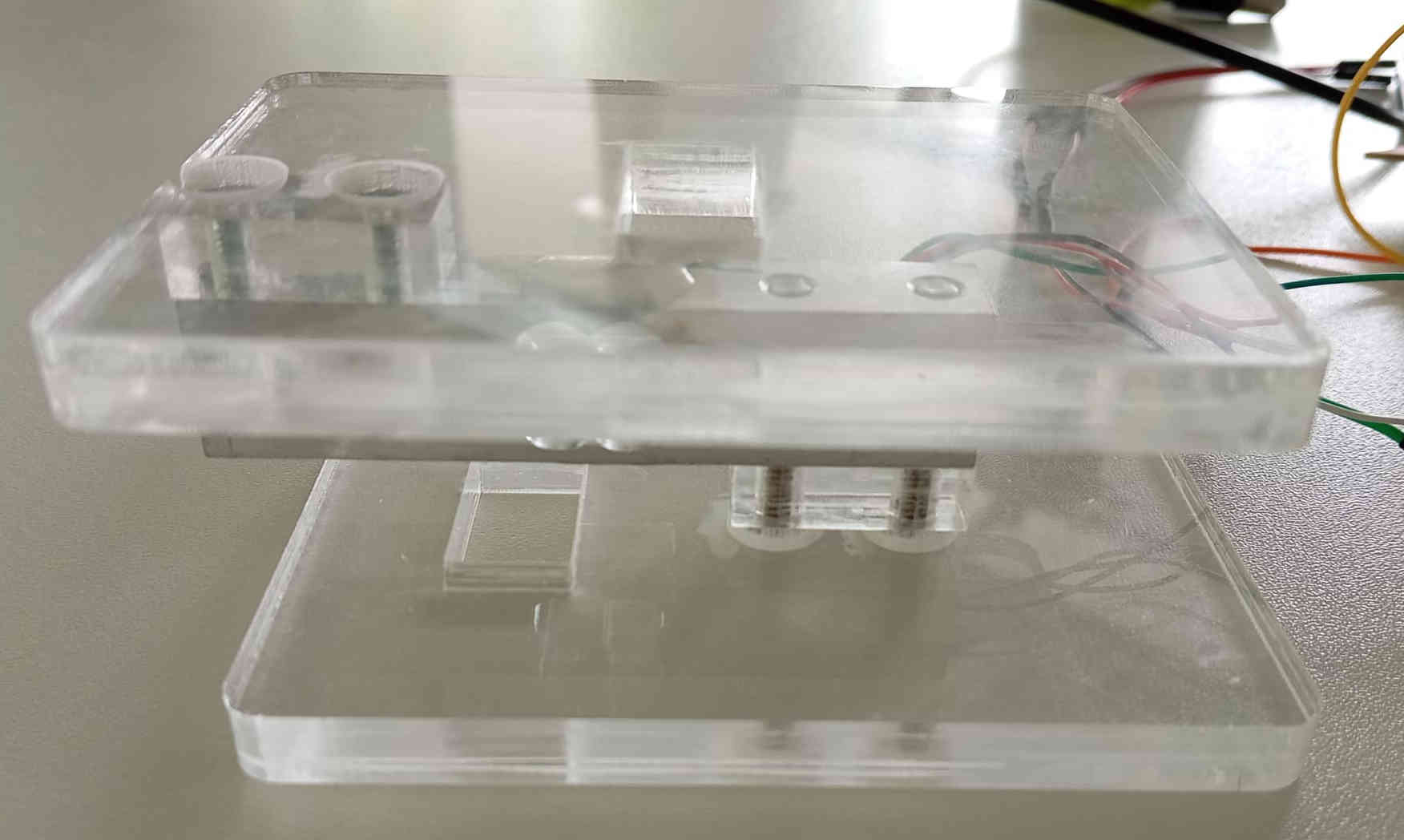
Calibrate the scale I needed to design a simple scale, the first parts were 3D printed and were okay if the weight did not exceed a cell phone. So a second design was made using the laser cutter with 8mm acrylic. The design is still the same, here you can download the DXF for laser cutting your own. After loads of tries and failures, finally got a result after many different code. Even the code presented in the data sheet was wrong. Thanks Ahmed who found the mistakes in the code and was able to fix it and explain to me what was wrong. Down below you will finds the working code. As well as of the build and images of scale working.
	#include "HX711.h"
	// HX711 circuit wiring
	const int LOADCELL_DOUT_PIN = 18;
	const int LOADCELL_SCK_PIN = 19;
	const int Calibration_Weight = 5000;
	HX711 scale;
	int y=0;
	void setup() {

	Serial.begin(57600);
	delay(2500);
	Serial.println("Start");

	scale.begin(LOADCELL_DOUT_PIN, LOADCELL_SCK_PIN);
	delay(2500);

	}

	void loop() {
	if (y<1){
	delay(1000);

	scale.set_scale();
	scale.tare();
	Serial.println("Calibration");
	Serial.println("Put a known weight on the scale");
	delay(5000);
	float x = scale.get_units(10);
	x = x / Calibration_Weight;
	scale.set_scale(x);
	Serial.println("Calibration finished...");
	delay(3000);
	++y;
	}

	if (scale.is_ready()) {
	float reading = scale.get_units(10);
	Serial.print("HX711 reading: ");
	Serial.println(reading);
	delay(3000);
	}
	}
Running code and weight test
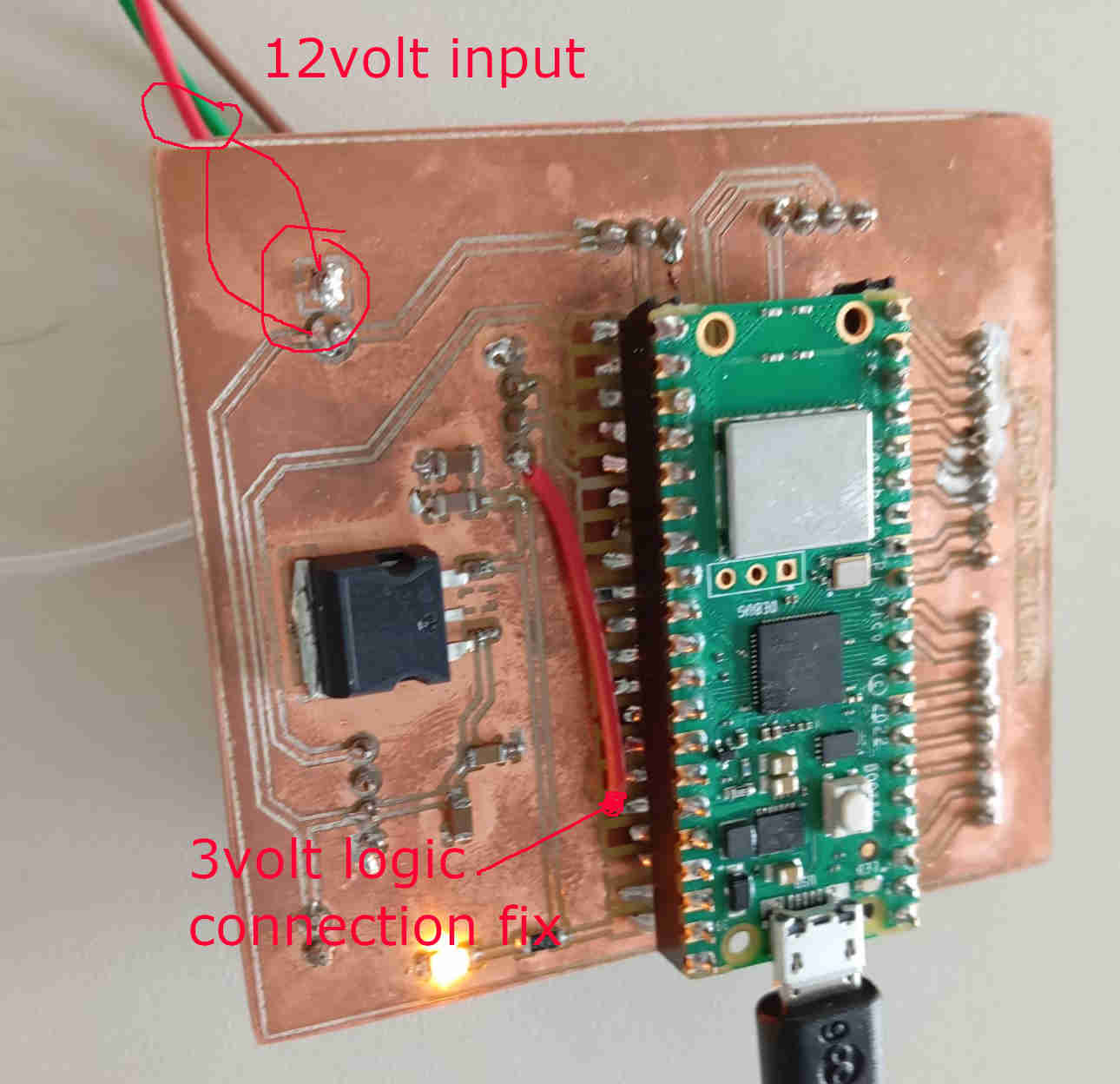
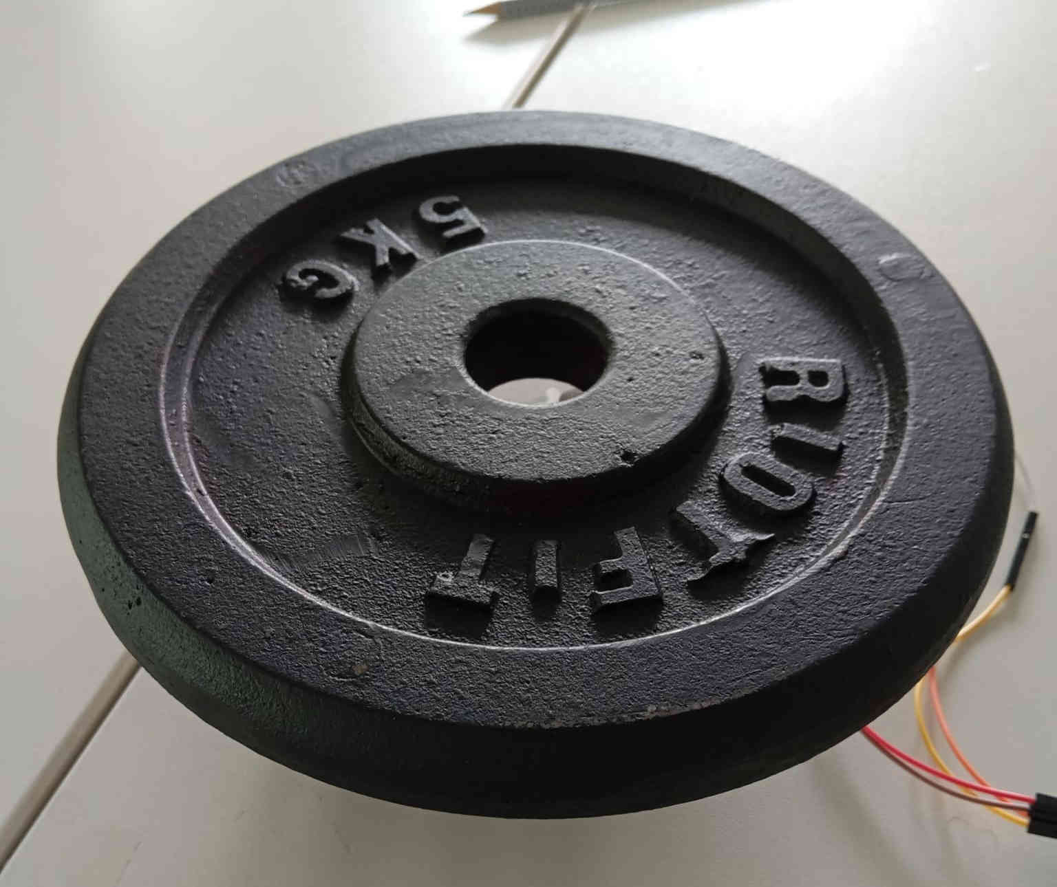
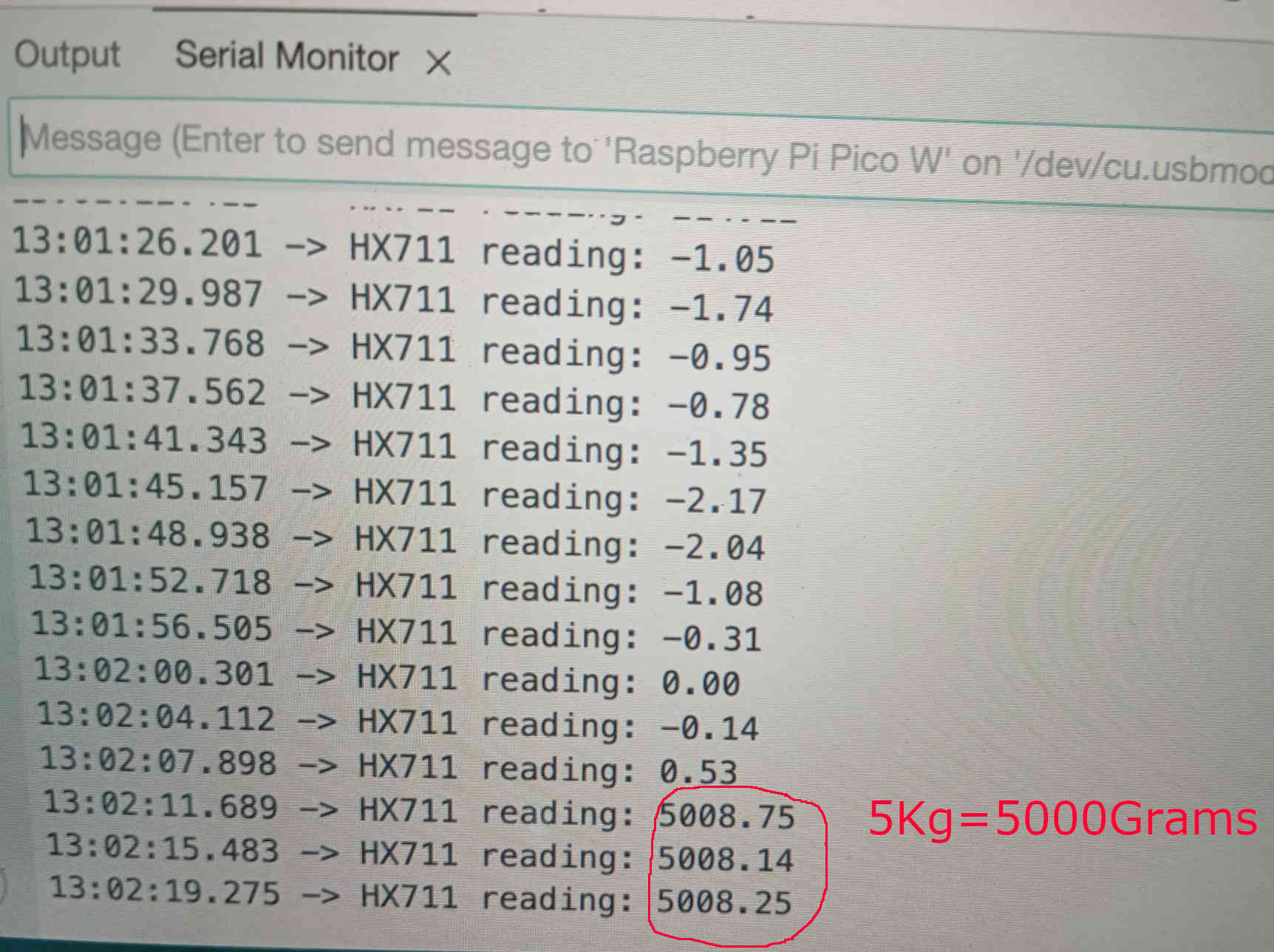
Now that the code is working, only a few minor adjustments were needed to the PCB. The issue turned out to be related to the Pi Pico W's 3.3V logic level. While this wasn’t a problem for the load cell itself, it did cause inaccurate readings on the Pi Pico W by using 5Volt instead. This led to some initial confusion, but once identified, the solution was straightforward. The solution was to just cut the connection to the 5volt and place a wire from the connection point to the 3 volt logic of the Pi Pico W. After this was done the scale could calibrate without any major issues. The reading were spot on and only deviated very little. This can be see as the 5Kg weight was placed on the scale.
Refection on the issues at hand
The mistake that was made with the logic 3volt and 5volt really made this turn into a long process to figure out what went wrong as well as the lack of proper working code. As there is not such thing as failures this serviced as vital lesson that even data sheets don't always telling you everything. Not everything ever works out as planed and this is very true for electronics. This was a battle that I am happy that is over with. I am still hoping to have the scale somehow introduced into the wind tunnel. I am still working on finding a good idea on how to add this feature. especially as the tunnel is small. In the end things may have gone sideways but it worked out, in that I am walking way with more knowledge.
PCB logic 3volt fix
When doing this fix if you do not want to recreate the PBC make sure to interrupt the original connection. This will stop the 5volt and let you solder on a wire to make the new connection as shown in the image below. The PCB also ran on 12volts during this process. This was also the case in testing the fan in the final project.
