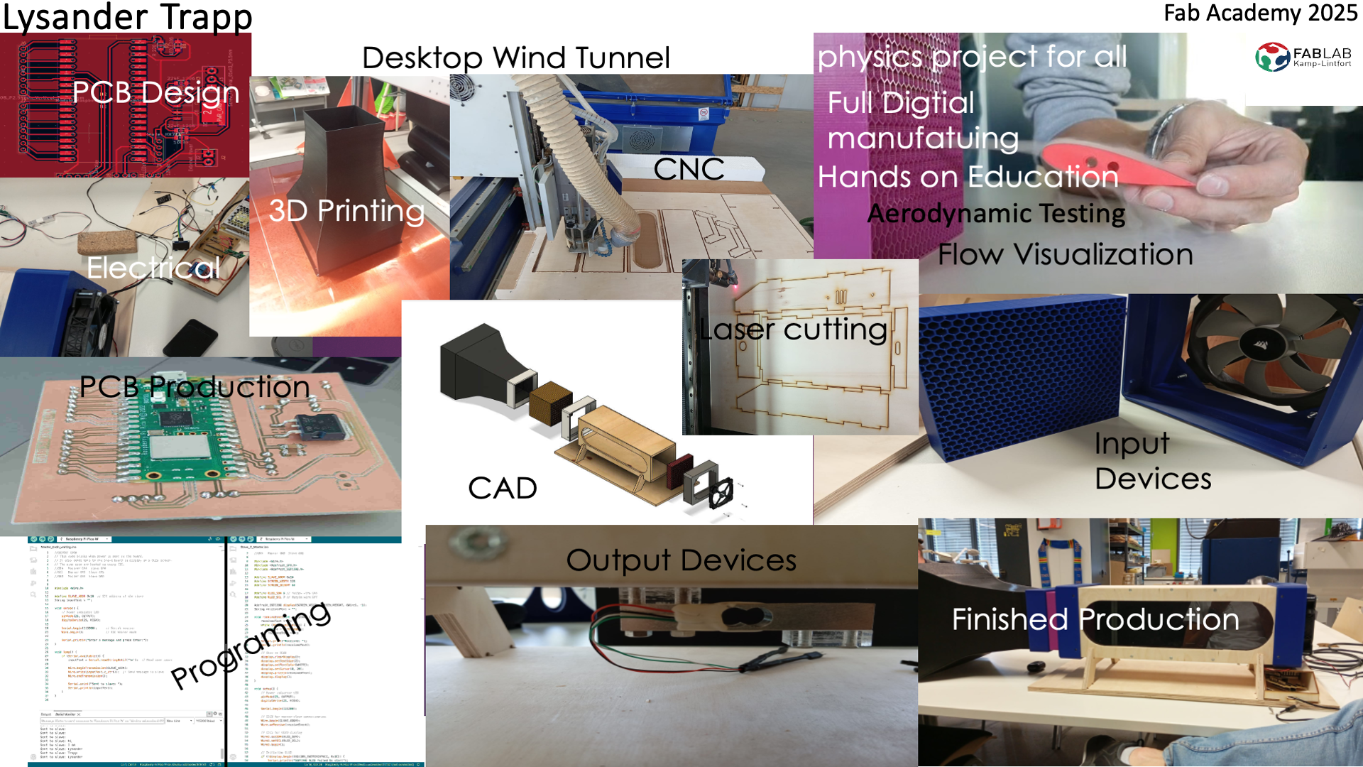
Final Project
The video was part of CAD week. For more info on how the video was compressed please check out the Computer-Aided Design, the information is at the very end. and was done with the help of this free to use webpage https://freecompress.com
Introduction to the Desktop Wind Tunnel Project
The goal of this project is to design and build a compact desktop wind tunnel suitable for testing the aerodynamic properties of small objects. This wind tunnel is designed with both functionality and accessibility in mind, making it an ideal educational tool for high school students and science educators.
Dimensions and Materials
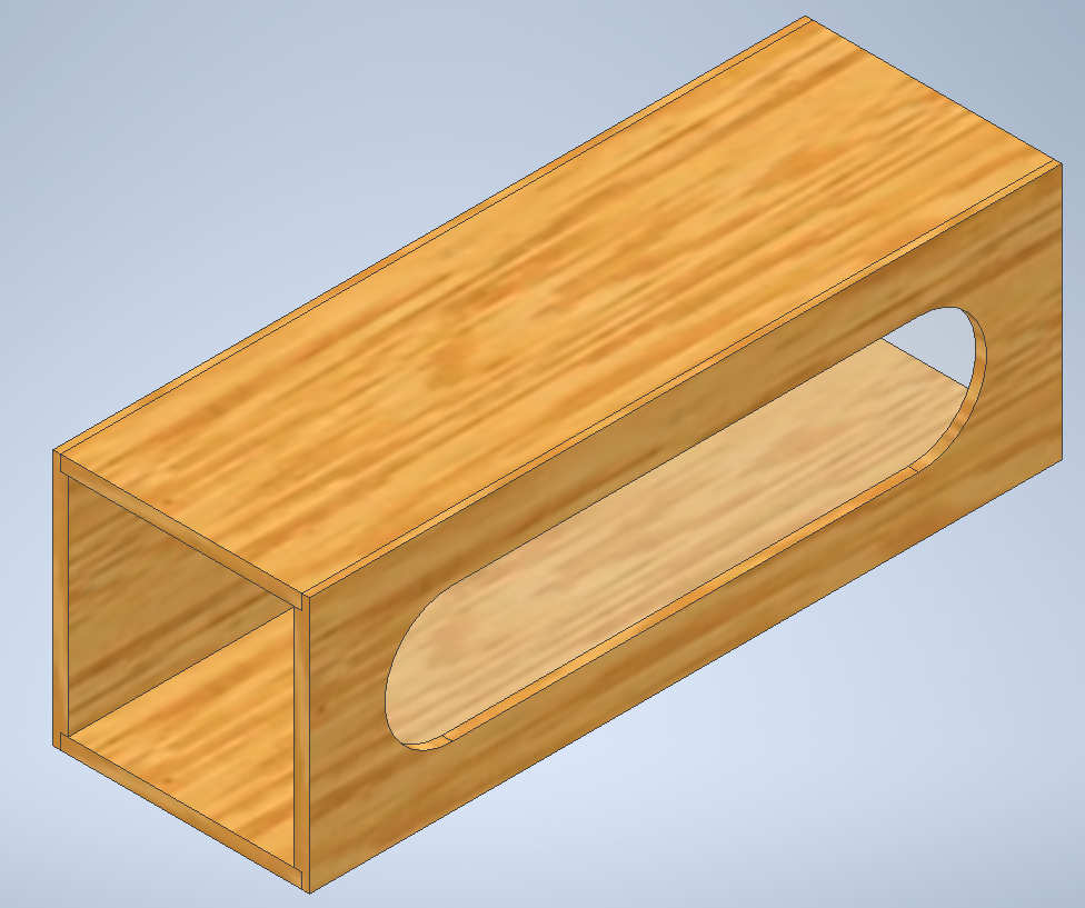
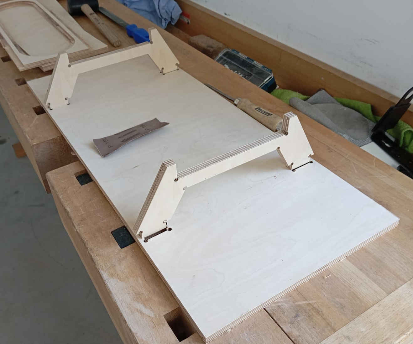
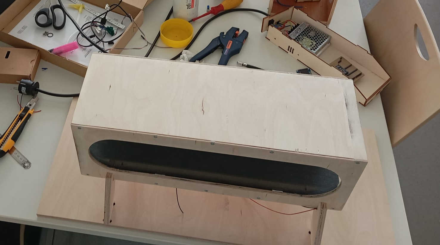
The main tunnel of the wind tunnel will be constructed from CNC-machined 10mm plywood. The tunnel will measure 500mm in length and feature a square cross-section with dimensions of 150mm by 150mm. A viewing window will be incorporated into the tunnel to allow for visual observation of airflow patterns and object interaction.
Laminar Flow
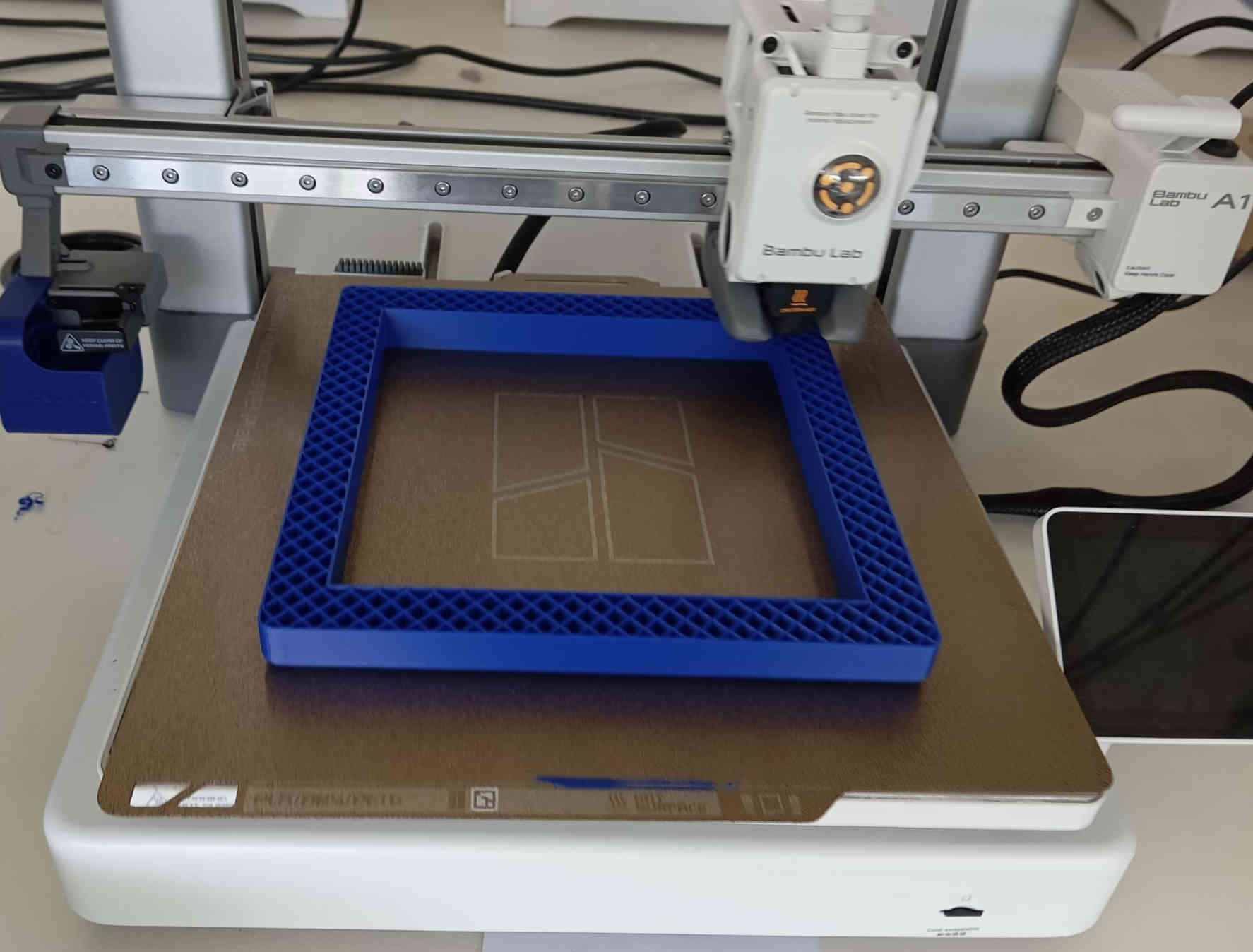
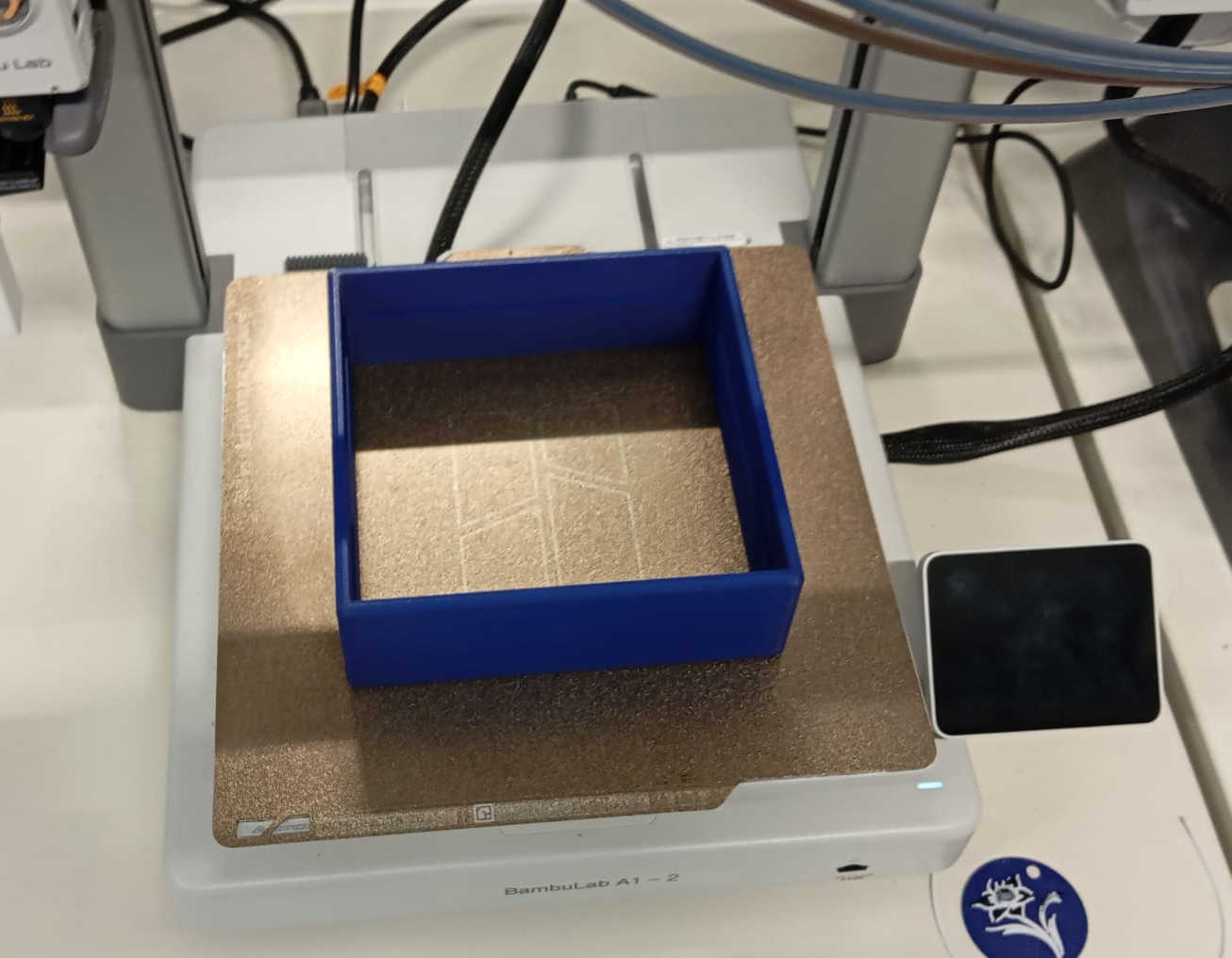
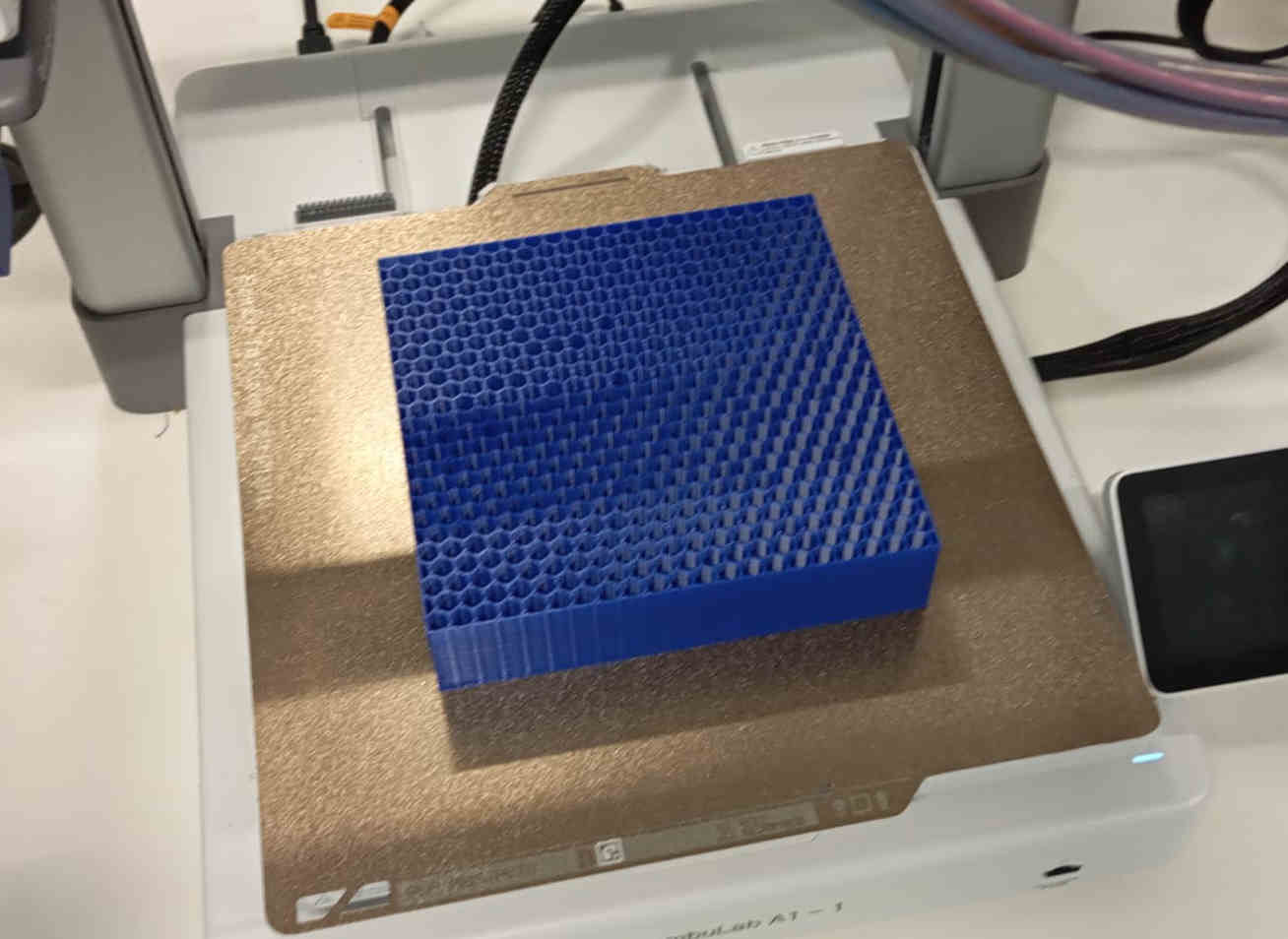
To achieve laminar flow, the wind tunnel will include a 100mm-long strainer positioned at the entrance of the tunnel. The strainer will feature a honeycomb pattern and measure 149.5mm by 149.5mm to fit snugly within the tunnel. This component will be 3D printed using a Bambulab A1 3D printer. Additionally, a finer wire mesh will be placed in front of the strainer to further eliminate any turbulence.
Airflow Generation and Control
Airflow will be generated using a PC fan with a PMT output and four wires. This fan will be powered by a PC power supply, ensuring a reliable and consistent source of energy. The airflow will be monitored and controlled using an Arduino microcontroller, providing precise regulation for experiments.
Visualization and Measurement
A smoke stream will be integrated into the wind tunnel to visualize the airflow around test objects. For more detailed analysis, the setup will include sensors to measure strain or lift, allowing for the observation of movements and forces acting on the object. These features will enable users to gain deeper insights into aerodynamics.
Educational Purpose
This project aims to serve as an educational resource, demonstrating the principles of fluid dynamics and aerodynamics. Its accessible design ensures that it can be replicated by science educators, providing a hands-on learning experience for high school students. The wind tunnel’s compact size and straightforward construction make it a practical tool for classroom demonstrations and experiments. By combining CNC machining, 3D printing, and microcontroller integration, this project showcases a multidisciplinary approach to engineering and design, encouraging curiosity and innovation in STEM education.
My first sketchs
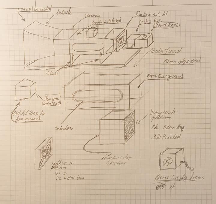
Main Tunnel thoughts and Ideas
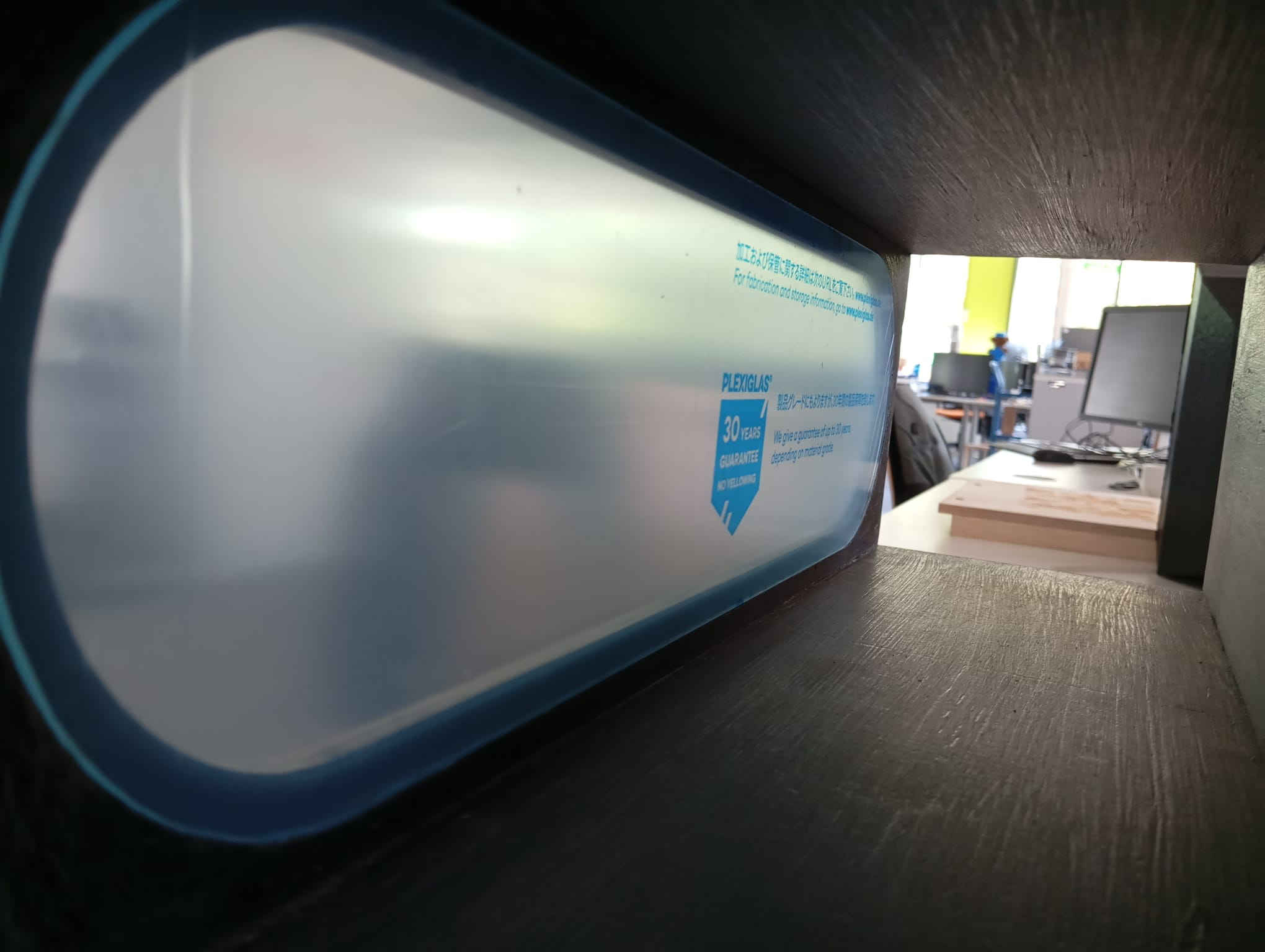
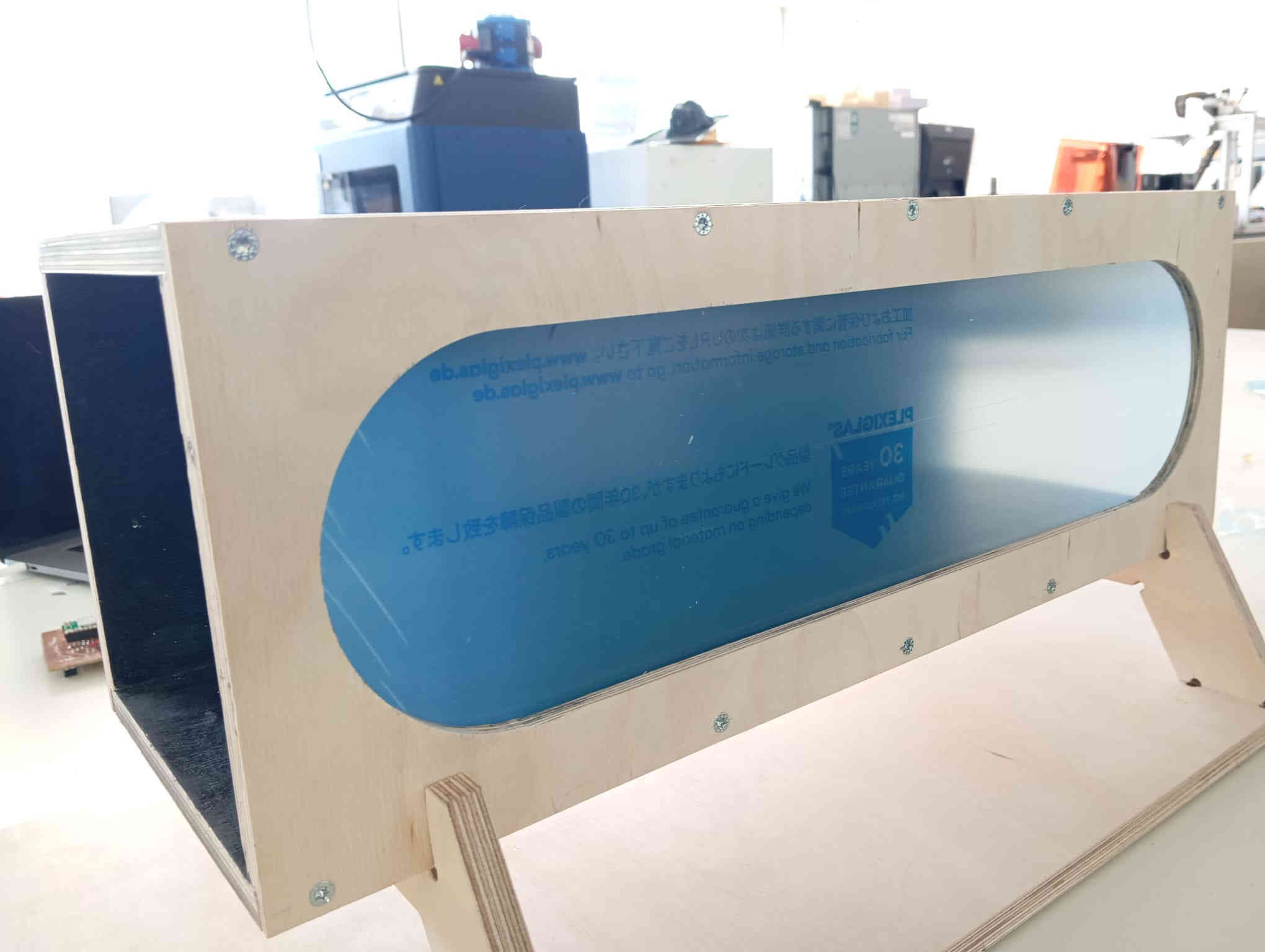
The main tunnel is designed so that anyone can rebuild it. I kept the joints as simple as possible. I could have gone ahead with the idea of using M6 screws along the sides, which I may still do for prototyping purposes, making it easier to take apart. The issue is that when using screws, you may run into leaks that could cause turbulence in the tunnel, defeating the purpose of having laminar flow. This is also why the window must have a tolerance of +0.3mm. The window needs to fit exactly in order to minimize leaks and be flush with the tunnel walls. Below, you can download the STL and DXF files.
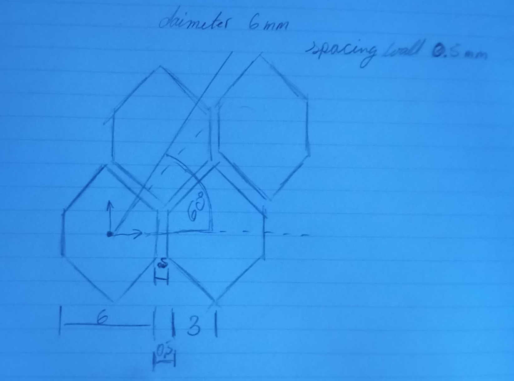
The Honeycomb
Creating the honeycomb was not a task that could be accomplished simply by repeating the pattern in
a regular form. The first thing I did to achieve the desired pattern was to understand that it requires
two paths to follow. One path goes straight, while the other needs to be set at a 60° angle to the straight
path. I initially tried copying and offsetting the pattern, but the result wasn't satisfactory
and introduced a lot of errors. If even one part is slightly off, it creates a noticeable gap.
For the air-strainer, this would be especially problematic if the goal is to achieve laminar airflow.
I realize that there is a lot of math involved in coming up with a working air-strainer. I will not be getting
into this in much detail. Typically you are trying to ensure that air flows smoothly and evenly while avoiding
turbulence or flow disruption. This process involves several factors, including the velocity of airflow.
CAD Shots
CNCing the Main testing tunnel 1.0
Here, I decided to CNC the main testing tunnel before starting the Fab machining assignment. Since the material I wanted to use was unavailable,
I modified the file to suit the materials that were on hand. This is true prototyping in its purest form.
Now that some of the major parts are slowly taking form, and having done all the math in the simplest way, the important part is that the tunnel is
built to fit a Pinewood Derby car. I also included the math for scaling, trying to determine how much airflow would be needed to maintain the scaled speed.
To give an idea of scale, the wheel speed of a Pinewood Derby car at 1/8th scale is 261 mph, while the real speed of the car is 12 mph (just under 20 km/h).
This provides the basic framework for the wind tunnel.
The pages do have titles, but the quest for solutions is somewhat random, as the flow of questions and ideas came to mind. I will provide a PDF, which could
be updated throughout the project.
This version of the test tunnel is still missing a finer mesh to further decrease turbulence within the testing area. However, for current testing purposes
and to get an overall idea of functionality and size, it is sufficient.
If, for instance, materials are not easy to source, I can recommend using cardboard as a testing material or even as a final material.
Cardboard is a great resource as it is easy to cut and locally available.
Below, you will see that in this version, I am using M3 bolts to hold the tunnel together. And yes,
as long as there are no loads acting on the tunnel pulling it apart, and the bolts are not over-tightened, the threads cut into the wood will hold.
The PCB for the Tunnel
Now that I have finally made my first PCB, which serves as the main control for the tunnel and will also help in collecting data,
the next step is to determine an effective method for measuring drag using a load cell. Currently, my thought process is as follows:
The tunnel is not very large, so placing a load cell inside would create unwanted turbulence. However, looking at my overall design,
I can mount the load cell beneath the main tunnel. This setup would allow for a string and pulley system, where an object could be
attached via a hook. Once the fan is turned on, we could obtain a force reading acting on the object.
The data collected here would provide a measurement of drag force, which, along with airflow velocity and object dimensions,
can be used to analyze the Reynolds number and aerodynamic properties.
The idea is simple Drag is a force that can be measured. This is the Resistant force as an object moves through a viscous fluid. This is
great as it allows us to use a load cell to measure the resistances. Unlike a scale where a weight is placed on top. Here the theory is to have
a wire pull up. In assignment 9 I am working on calibrating a load cell. Sofar I have at least gotten it to show some reading but not ones that
could be useful. But let take a look at the design that I mentioned here.
To make this work the design calls for two pulleys placed so that one is under the tunnel, where a small hole will be needed to
pass the wire/string through. After talking to couple of people This may not be great idea. The reason is that the more bends
and angles are involved the less accurate the results may be. Looking over the idea to have a small rode being pushed or pulled
could work as well. Another idea is to have the sensor placed inside the tunnel.
In assignment 10 finally got to test the fan. The 120mm pc fan puts out about 10 cubic meters of airflow per minute. Even with the fan not
bing fully enclosed it was pulling air efficiently to show Laminar flow. Here is a short video of the flow being blocked by my and hand. Later
on I looked how close to the walls I could get with the help of the Professor William Megill. The flow was best in the middle of the tunnel. Showing
laminar flow. The closer the test strings got to the wall the more turbulence appeared. With in about 25mm of the back wall it showed
that the laminar flow was turning turbulent. This may be cause of the fans size of 120mm and the tunnel being 150mm. For now the result is
good.
How to test your laminar flow
To visually see if the flow is laminar or turbulent, I did look into getting a old fog maker. This was easy as there is one in the lab but its seems to be defective. So rather than wast time trying find the problem, the simple solution is old school but will work even on modern cars and bikes. Before wind tunnel testing we would just attach strings to the car and take it down the road to see how the air flows around the surface. This method is still used on sails of sailing boats. So here is a small list of parts needed.
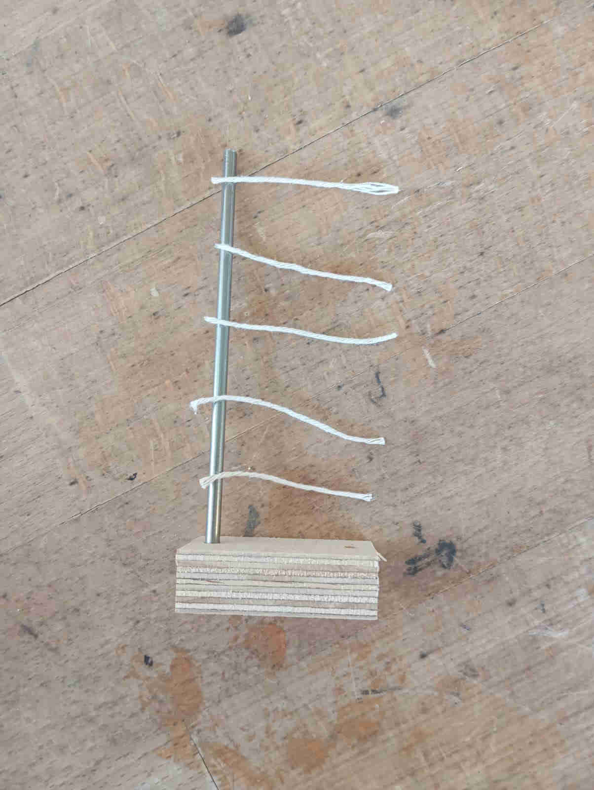
Space the strings so that they are evenly spaced and allowing for test in a good rang of the tunnel.
Hot glue the string on. Next attach the dowel to the base, can be a piece of wood with a hole
to fit the dowel into.
to test different areas in the tunnel just move the DIY flow tester around to see where the best laminar
flow can be found. Near the walls there will be some turbulence, this normal as the air will want to grab the
wall. The flow should be best with in the middle if the tunnel. This is where you wan to test later any
object.
The math
How I came to the idea of building wind tunnel and how I decided on the scale and size. As a kid I was really into airplanes and in 8th grade I had a science class where we explored winds and lift. That same year this class got to Embry-Riddle Aeronautical University, Daytona Beach Florida. This is where I saw my very first and only wind tunnel and I have wanted one ever since. As I also teach MINT (STEM) in germany and I want thought this to be a cool project, I grabbed all the masters papers I could get my hand on and started reading. So I looked at the very basics of the math needed to design a small version of a wind tunnel. I wanted to add in all this math that was done to this point and have a all the explanations for what does what. Unfortunately I never did find a way of writing all the math equations. So at this point for anyone who would like to to have a look of what I did, here is a link to day download the zip file of photos. It is nothing crazy but it helped in finding out some this questions that came up long the way on designing the test chamber and the air-strainer. It also let me figure out what to expect when placing a Pin wood Derby car into the tunnel.
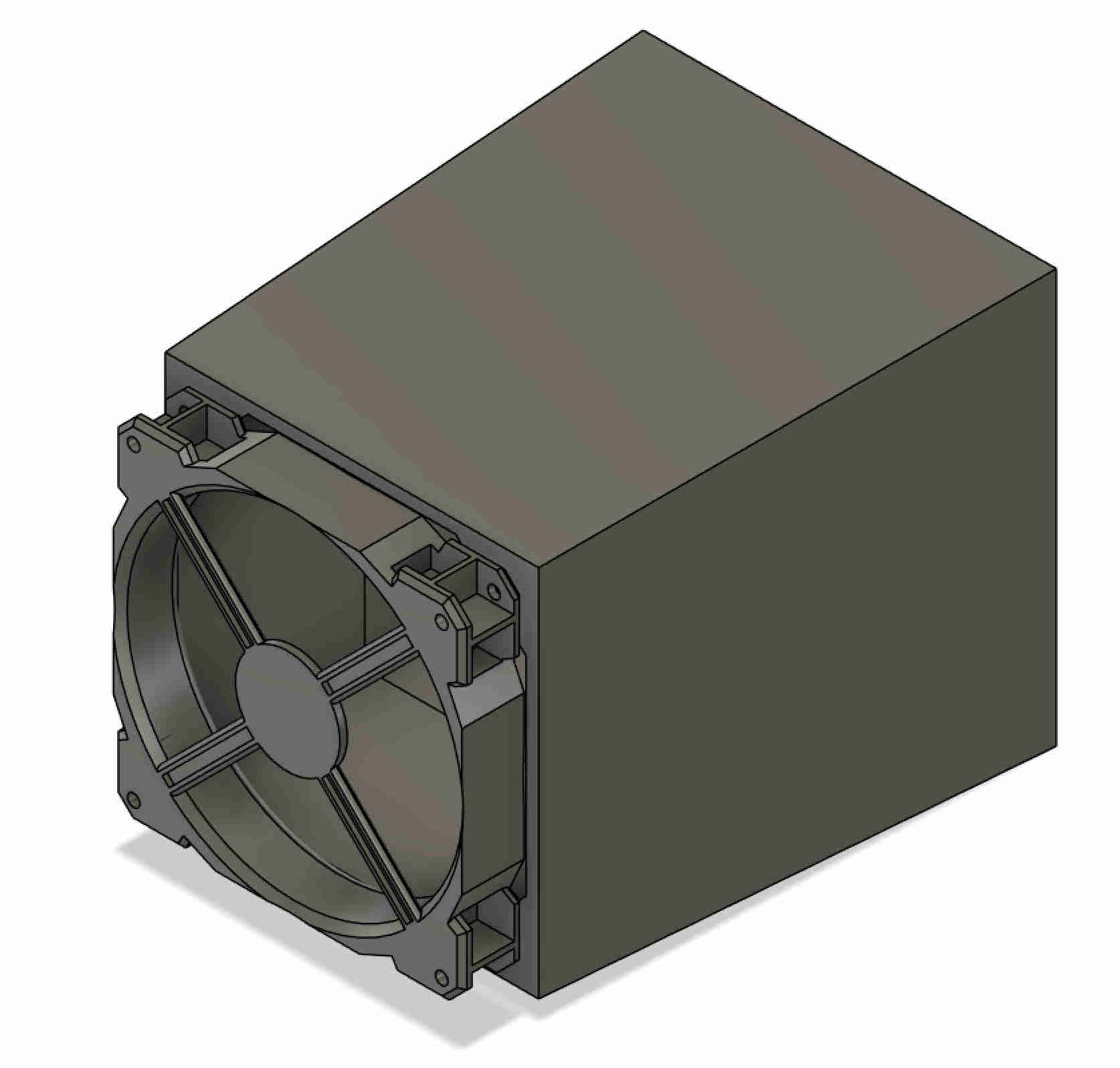
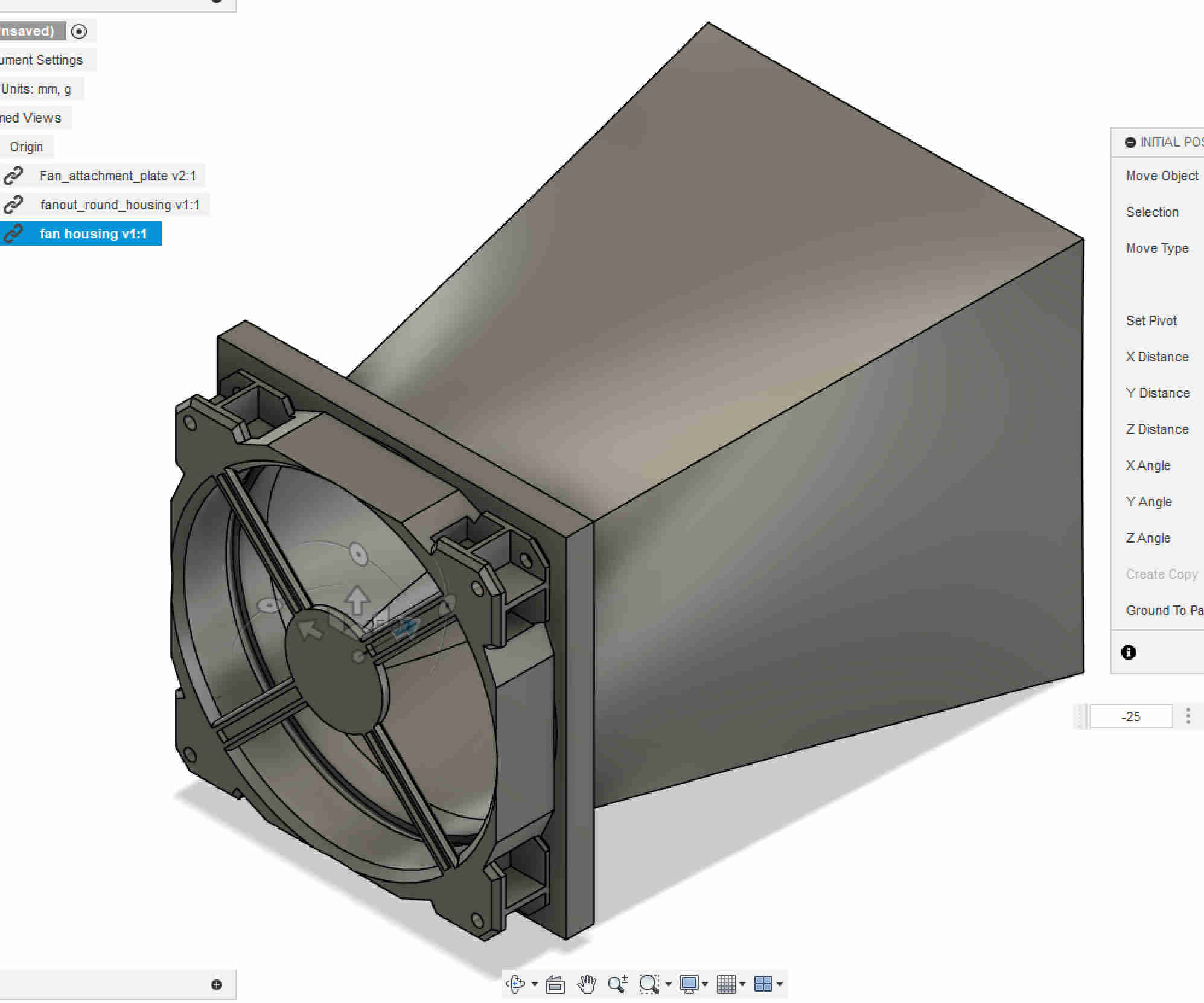
Fan Exhaust (Diffuser)
One of the issues coming up was how to attache the fan to the 150 x 150 mm cross-section? the fan is only 132 mm in diameter. To to insure that there is no backflow or dead space makes this a hard problem to solve. If the shroud goes from the testing cross-section to the cross-section of the fans 132mm the back pressure increases.
After another long search on google and looking at videos and papers from MIT
and NASA found that this type of design has been used in closed wind tunnels.
At the moment the main worry is that this shroud would upset the laminar flow in the testing section.
Currently the tunnel has good laminar air flow. Now before the math was more of a concept to check if it could even be done at the size. This was done without the design even being
done with random information. Since than the tunnel has come into life and a simple analysis of the flow, using sting on a bar showed good flow with the core of the testing section.
What is happing mathematically
In the testing section without the air-strainer. The cross-sectional area is 0.15m x 0.15m, the fans is 120mm in blade diameter and spins at 2200rpm. The air density
is 1.2kg/m^3, the viscosity is 1.8 x 10^-5 Pa sec. >Assuming that the pc fan has flow "Q" of 60-80 CFM and we use the middle value of 70 CFM, converting
this value to meters we get a "Q" of 0.033m^3/s of flow. Once we have this value and the cross-sectional area of the testing tunnel you can calculate the the velocity
of flow. Flow speed is velocity "V" = flow rate "Q" divided by the Cross-Sectional area "A". Plugin the values and we get 1.47m/s.
This value is needed to see what the Reynolds numbers are in side the testing section. Basically Reynolds number are
unit less values that are used to check for flow behavior such as laminal, transitional, and turbulent flow. This lets us see what is happening in the wind tunnel without
the air-strainer. Re= ρ V D / μ plugin the values and we get 1.2 x 1.47 x 0.15 / 1.8^-5 = 14700.
What does this value tell us? It states that we have really turbulent air flow in tunnel. This will come apparent when doing the same mathematical process with the air-strainer, as this reduce
the air flow, thus giving a lower Reynolds Number "Re". Using the same formula that was used be for to find out "Re" value but this time we add the air-strainer. The dimensions of the air-strainer
are 150mm x 150mm and 100mm long each cell is 6mm in diameter. Looking at the air-strainer we get the following result, Re_cell = (1.2 x 1.47 x 0.006) / (1.8 x 10^-5) = 588.
This is a great result as it tell me that that my string test has shown that there is laminar flow. The Re_cell value of 588 shows that indeed there is laminar flow
as the Re value is less than 1000. Any value above this will be transitional laminar flow. Meaning it will straighten out again. If the Re value is greater than 2000,
there is only turbulent flow.
This very interesting as it shows when the air-strainer is removed the airflow is greater but turbulent. This shows while the fan can generate airflow up to 1.4 m/s
in open conditions, introducing the flow straightener significantly reduces that velocity due to added flow resistance and a drop in static pressure. After passing
through the strainer, the airflow slows to approximately 0.06 m/s, which corresponds to a Reynolds number of 588. This lower Re value is well within the laminar
flow regime, helping to ensure stable and uniform flow conditions in the test section.
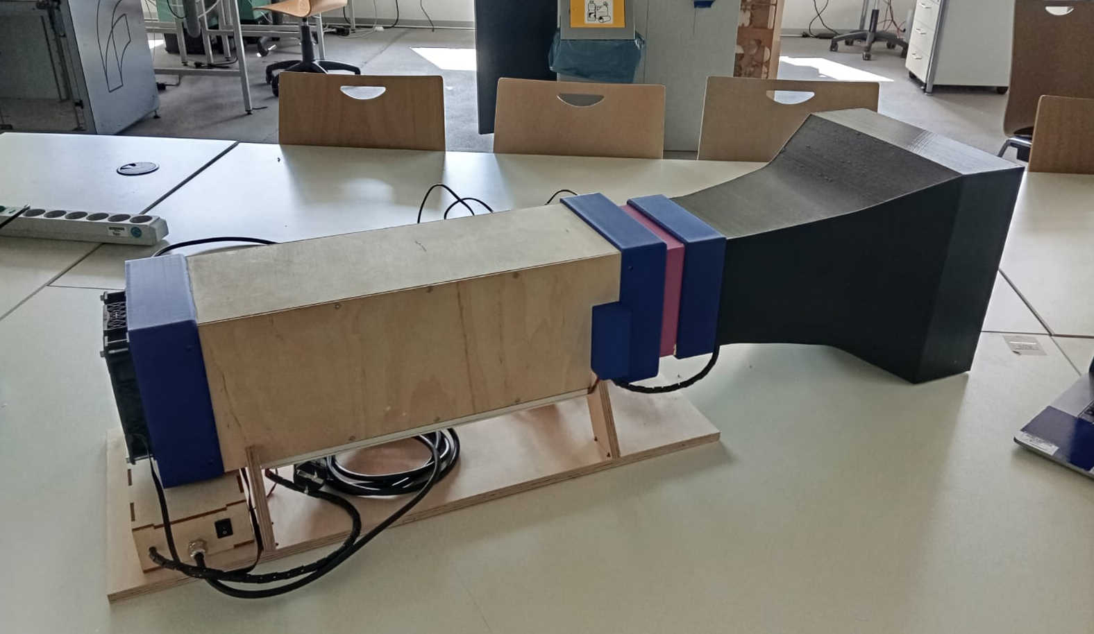
The build
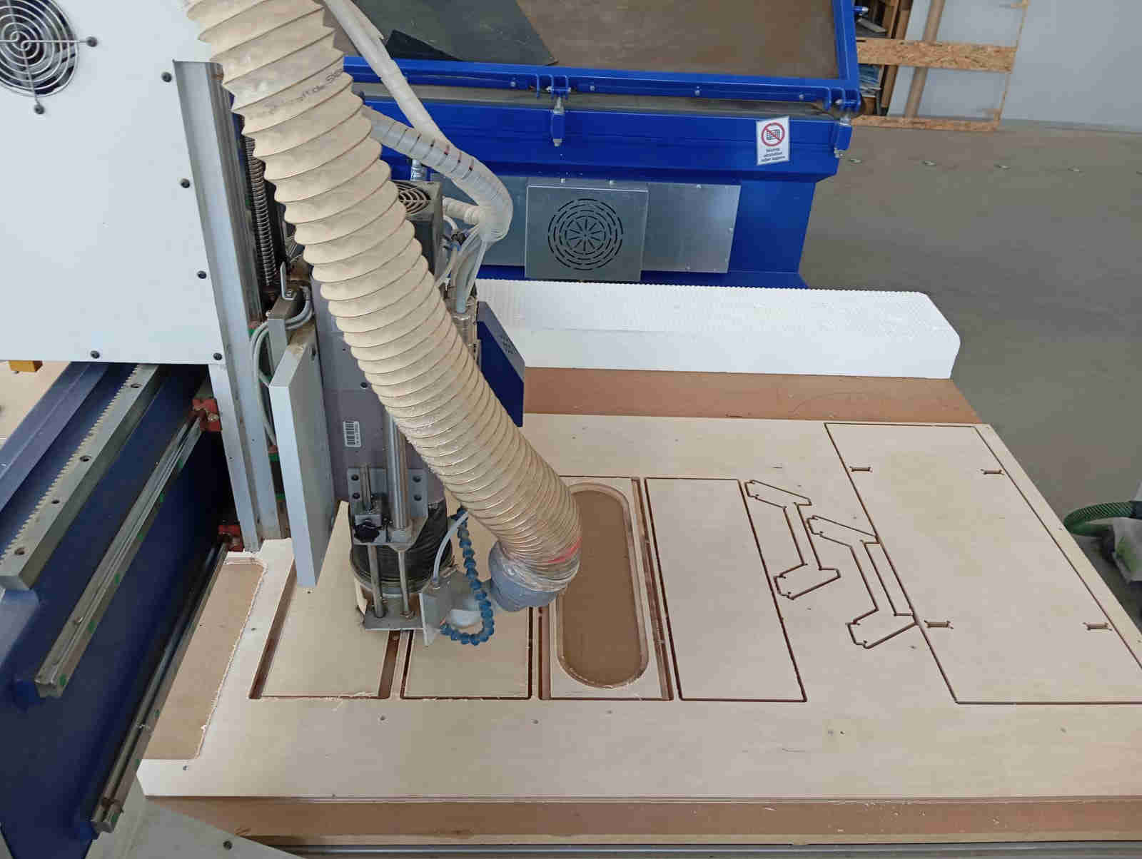
Looking over the last steps we have all the parts done in CAD and can now move on to building the Testing section of the tunnel. For this we want to use
the CNC. If a CNC is not at hand but other power tools are available, such as a Table saw, hand router, jigsaw can be used to make the testing section of the tunnel.
Or any other choices of hand tools. The Plywood had a small bend to it and had to be screwed down to the CNC table. This meant the screws had to be placed
carefully, so not have the milling tool run into the screws. This meant that the cnc would get paused ever so often to allow for a screw to be placed when the wood
would bend up. Over all no major problems popped up during the CNC job.
Before all of this took place all the parts where laid out and placed in such a manner to allow all the parts to be cut out with any interference in Fusion 360.
In CAD all the parts where also adjusted for the manufacturing process to make sure that nothing would go wrong. For more information on this process you can
look at the assignment7 where I go through the basics of using a cnc with Fusion 360. An alternative to Fusion is FREECAD which
now also allows you to install CNC Processing functions.
The Tunnel
In order to have a better visual when a stream of water vapouris added, the inside of the tunnel needs a coat of paint. As I personally was unsure if the later when adding LEDs would end up reflecting of the bare walls would be an issue, and as the tunnel is made of wood and the streamlined water vapour could add water to the tunnel, I decided to add black paint to the tunnel. Since the weather was nice the paint dried really fast and could be sanded. The paint was brushed on, in 3 layers. Each layer would get sanded to remove as much of the bruch strokes to minimize any unwanted turbulence's coming of the walls. The reason this was done was to avoid having the air stick to the walls even more. This is also an a problem with big wind tunnels. As this tunnel is made of wood and the wood fibers can stick up causing turbulence's sand and painting helped smoothen out the the turbulence.
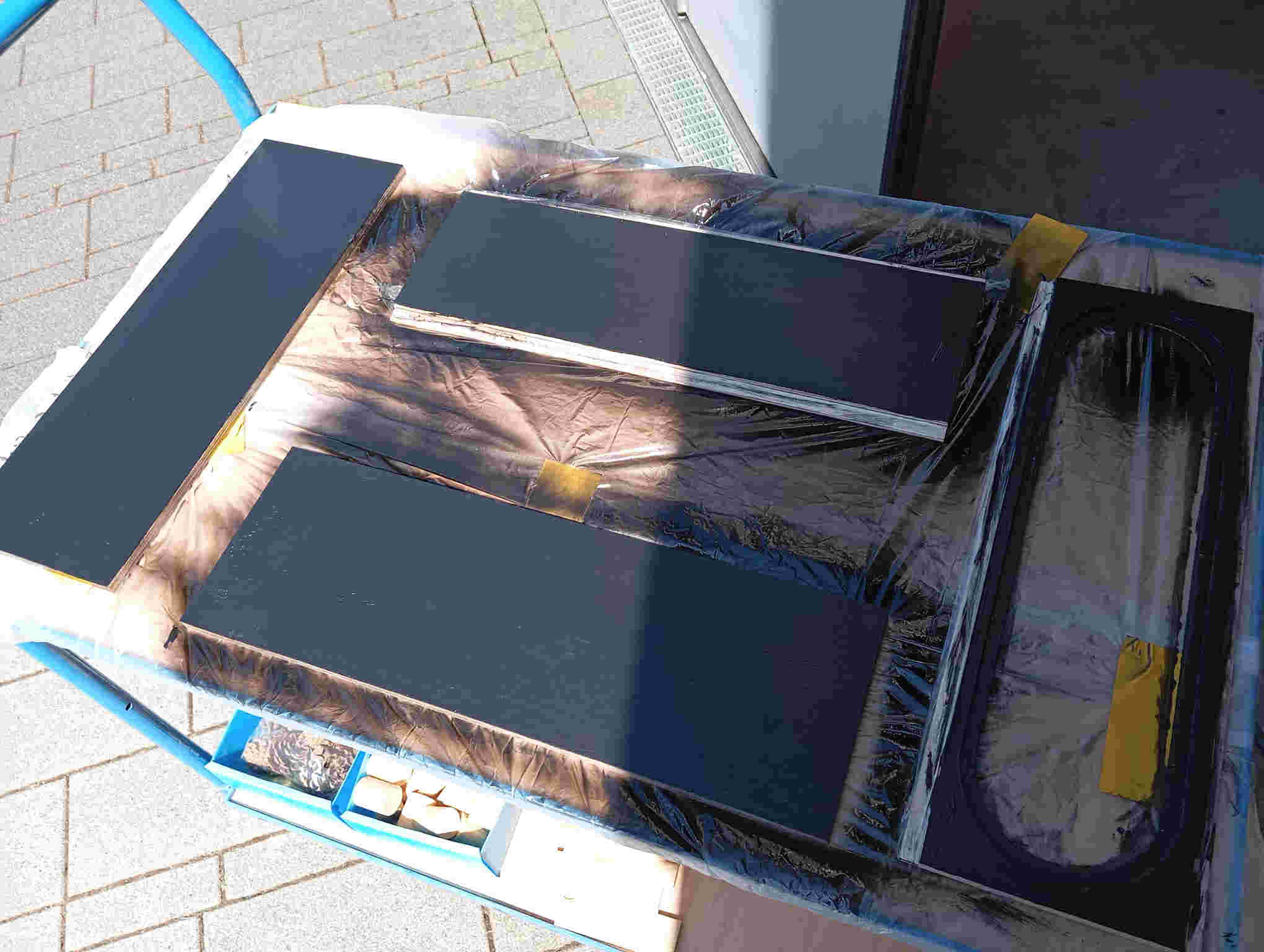
After the walls were painted and the paint was smooth to the touch, it was time to put everything together. The one thing that I
still ended up having to was scrape the paint of the parts that where going to be glued and screwed. The reason for this was that
wood glow will not hold to paint well. Using a razor-blade the paint was scraped off the sides. Second reason is that the paint adds
a thickness to the joints that we want to glue together. Tip here is to tape off anything that does not need paint.
Once all unwanted paint was removed from the joints, clamps were used to help line everything up and holes were pre drilled for
the screws. Pre drilling keeps the screw from splitting the wood which can happen even with ply wood. Once the holes were drilled
the clamps could be removed and the wood glue could be added to the joints, and the screws were used to help line up the walls. The screws
also worked as a mechanical clamping mechanism. If the screws are unwanted they can be removed later. To fill the
screw hold the option is to drill the holes out so that a wood dowel could be glued in. I liked the look of the screws, therefore choice to
keep them. At the same time the stand for the tunnel was just sanded to round over the sharp conners and remove any splinter. The legs of
the tunnel are interference fit(friction fit), holding them in place. Here no glue was used. The reason for the
glue on the main tunnel was to insure that no drafts could enter the tunnel.
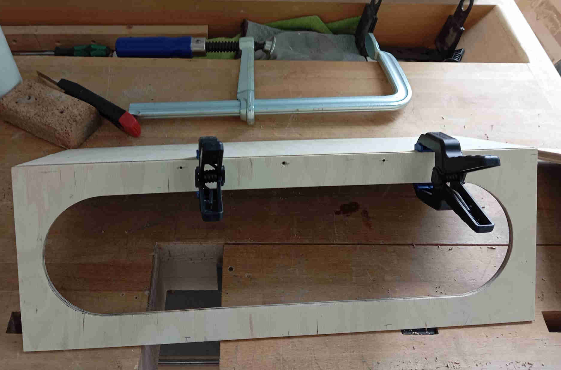
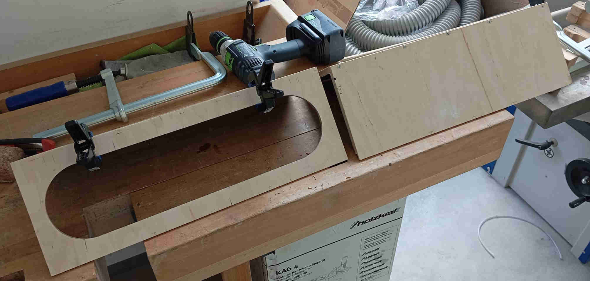
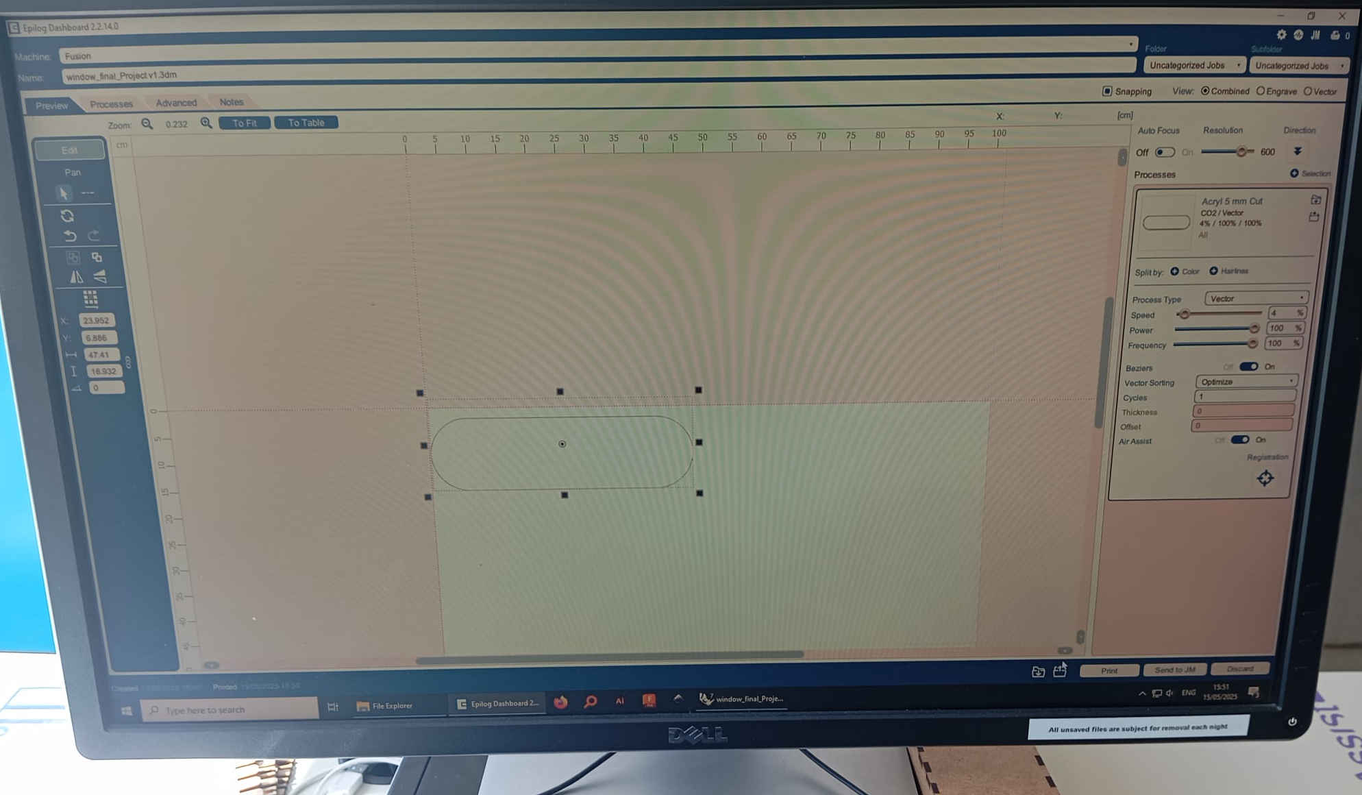
The window
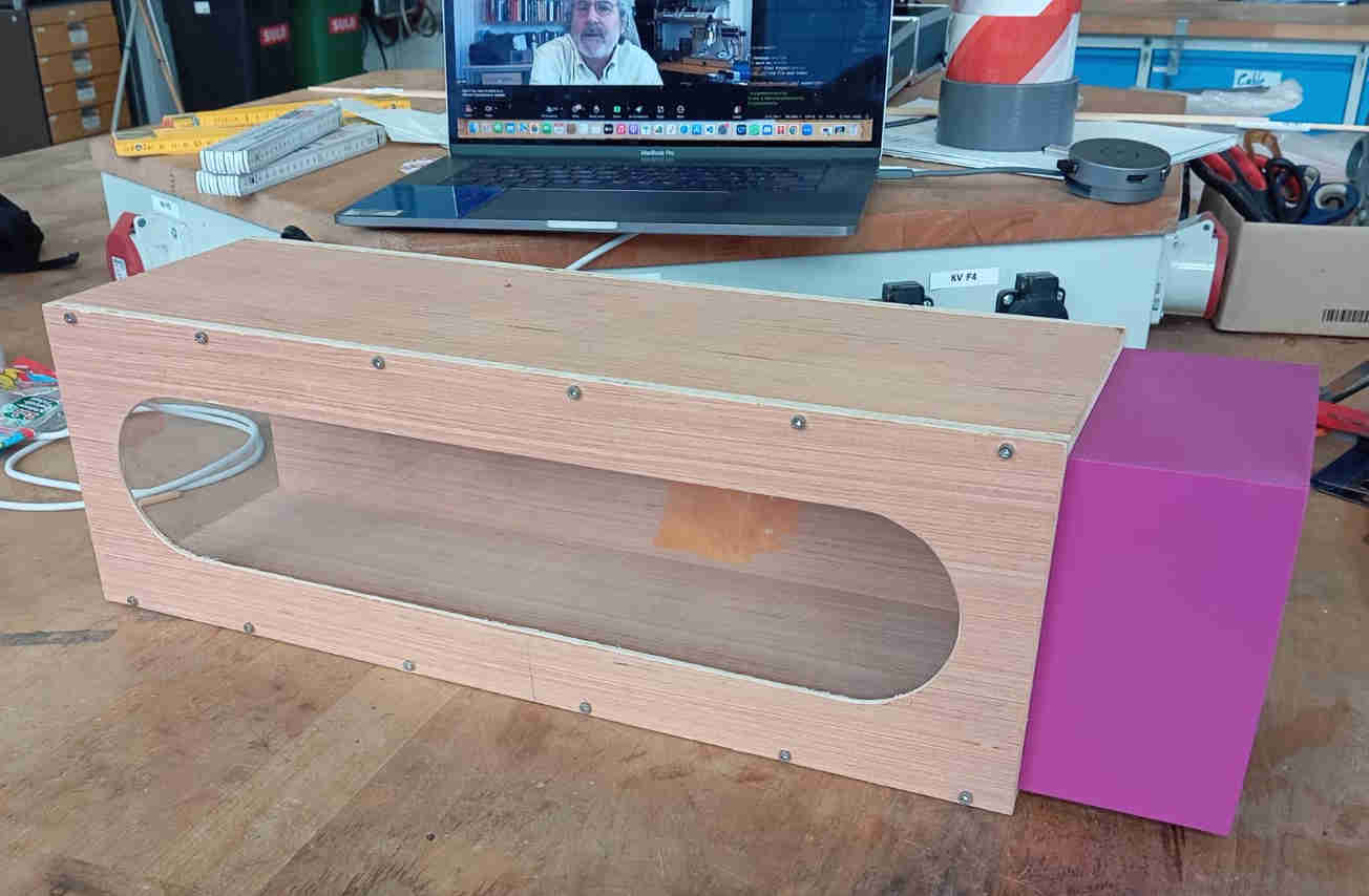
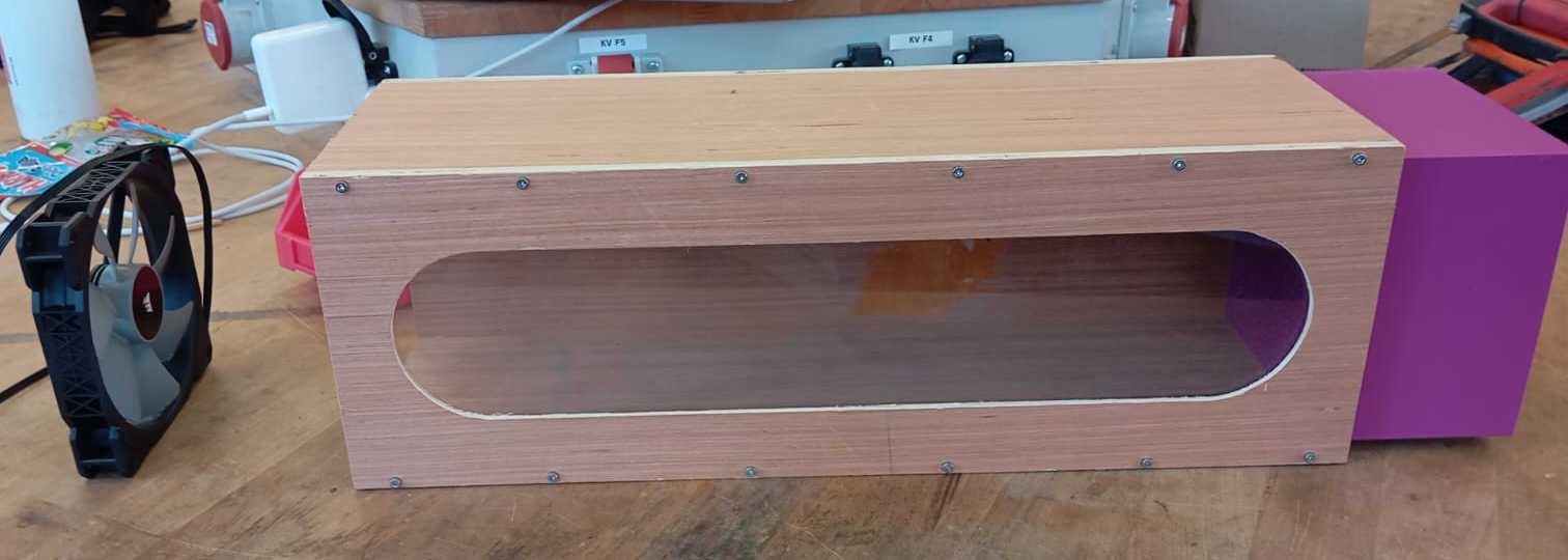
After everything is glued, the the viewing window needed to the made. For this the Laser cutter was used to cut 4 mm thick plexiglas. Little trick to keep any burn makes to show keep the protective coving on the plexiglass. Once the window was cut and the fit was tested, some double sided tape is was used. As the window was a press fit, there was no need to have all sides of the window glued in place. As testing showed later there are also no air leaks from the window into the tunnel. Silicone could also be used to seal off the window. But that is a messy job and also would add more drying time and cost to the project.
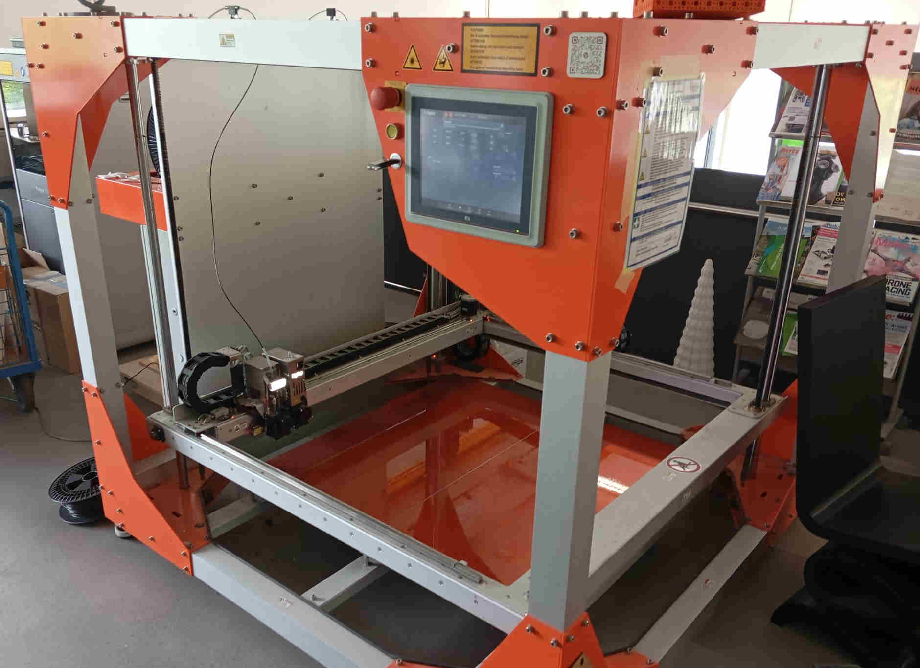
3D Printing
Even though I did not want to have so many 3D printed parts, I ended up having a lot of the parts 3D printed. This was really not the goal as I wanted to make most of the wind tunnel out of wood using the CNC. But as the Fab Lab has those nice 3D printer from A1 Bambu lab Printers that make fast work of making parts for this build in record time and allowing me to concentrate on other tasks at hand like system integration, this was an open invitation to start the Fab Labs 3d printing Mill operations to get all the connecting parts done. Including me to use the a really big 3D printer, to print the Air-Intake. The bigrep 3D printer is an industrial product that can print bigger parts in 1:1 scale. All parts haven been printed with PLA (Polylactic Acid) this is a plastic made from sugar beet or cornstarch. Making it a bio-plastic made from renewable resources.
The bigRep
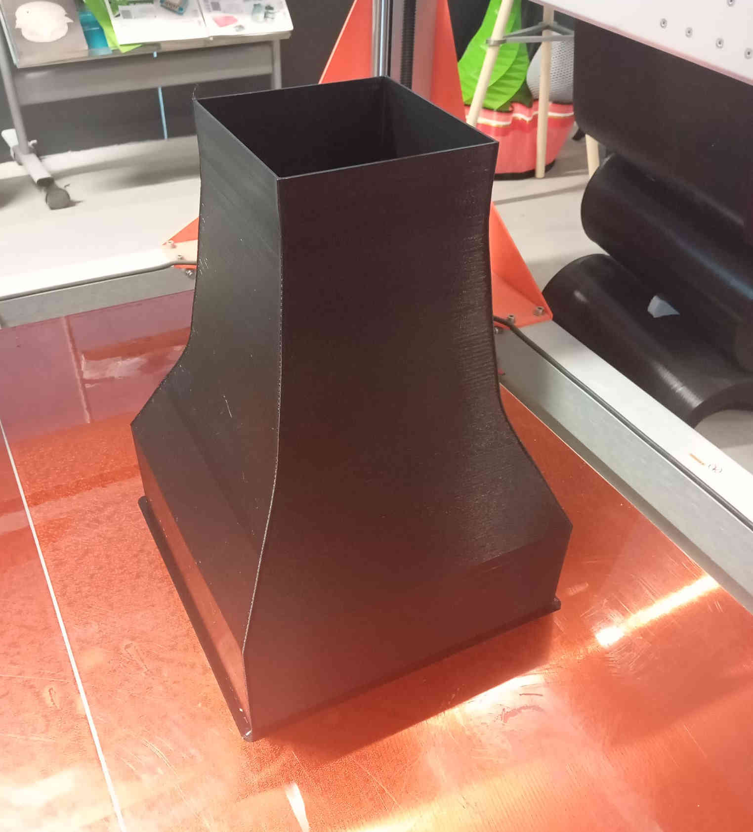
Now as of right know I am not sure how much the Air-Intake really helps with the amount of air flow in the testing tunnel. This will have to be tested with the help of the Load cell . In theory the are intake should be 4 x the cross-sectional Areal of the testing section of the tunnel. The Air-Intake may also change in the future, as there are many different shapes that I would like to test.
A1 Bambu Printing
All the parts were designed to have very tight tolerances, this was so that the parts will hold without any fastener. Which was a goal of the project. You will notice that the connections to the tunnel do bolt holes in the design. This was done in case the tolerances from the 3D printers where not as good or the main tunnels tolerances where off. Giving the connections a lose fit that would allow the tunnel to fall apart.
The Assembly
This part of the project was really great to have come along after the time sent designing and hopping that it would all work out.
It marked the half way point of the final project. Now only the system integration of all the electrical
parts is missing with the programming. After fine tuning some parts, which mostly involved sand the plywood of the main tunnel, which was a
little to tight, the connecting parts lined up and slipped into place. As all the parts are assembled to the Tunnel the more and more
it starts to look like a Wind Tunnel.
the first part is the main testing section of the tunnel. Here the stand and its based should be assembled. Next the we can assemble the Defuser and Air-out strainer with the
120mm PC fan.
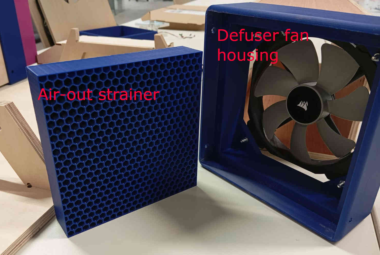
The Air-out strainer is placed into the defuser connection where the 120mm pc fan is mounted
with four M4x30mm bolts. The Air-out strainer is an idea that I wanted to try out to help keep the air flow
laminar. As it turns out this was a good idea as it keep the turbulence from blowing back into the tunnel. The fit of the air-out strainer should just fit
it may need a little force to push it onto place. If the fit is a little loose add some painters tape to help hold it in place.
Stand and Tunnel
Defuser assembly
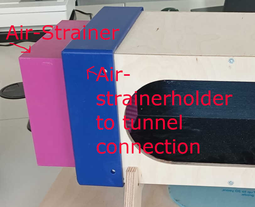
Air-strainer holder
The tolerance is tight here and the two parts will need to be pressed into each other. This did require some wet sanding on all fours sides of the, here in Purple, air-strainer. Thee reason is to have as little as to no air gaps that can cause turbulence.
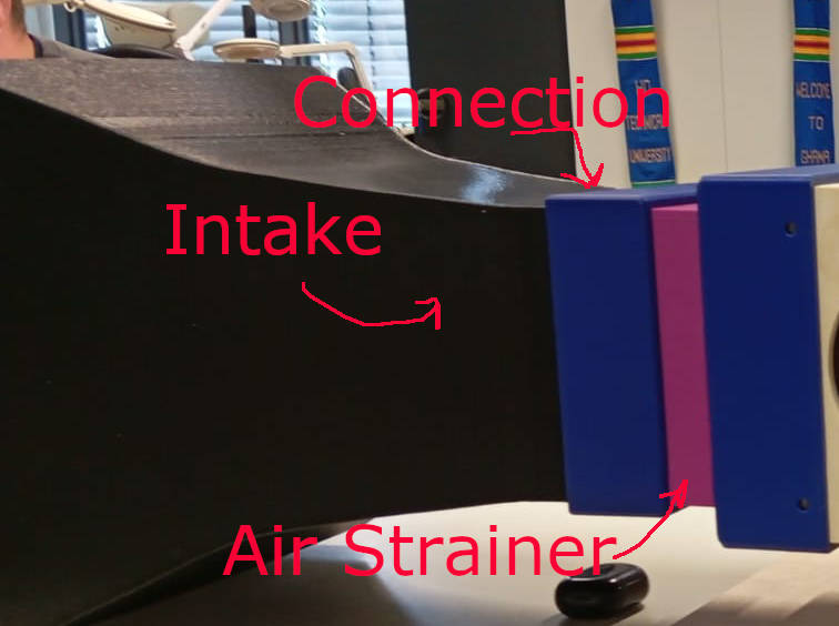
Air-Intake
Here the Air-intake should connect just a small push to the connecting piece that gets pushed onto the Air-strainer.
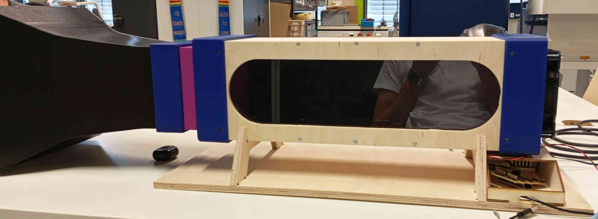
Main assembly completed
After some post processing, the main assembly is completed. From the Air-Intake to the PC Fan should be assembled. If you are wondering if there is not a part missing at the end of the tunnel there is not. As the air flow coming out of the tunnel is rather slow it air does not have to have a defuser. I did consider adding one, but as the fan at the end will have to come of every time a model is mounted in the tunnel, it would also end up costing more to make. This is primarily a tool to show kids how the are moves and flows around objects. The assembly result can be seen blow:
Electronics
This is a short summary about the different sensors and other electrical modules that are installed. For a full version of the check out the page on System Integration
there I go into more detail. How everything is laid out. To understand how the micro-controller PCB works and to find where everything gets
connected and look at Electrical Production. For all the device for input and output check out input devices, for output devices.
The wind tunnel uses the following electrical devices which all work over either the IDE serial Monitor or the an Interface, this includes a Load cell, OLED display, 120mm PC fan,
LEDS, and 3 super sonic Humidifier modules.
The LEDs help highlight the water vapour (smoke) as the light reflexes of the water particles. The water vapour is also used to show
how much drag or turbulence can be caused by the object.
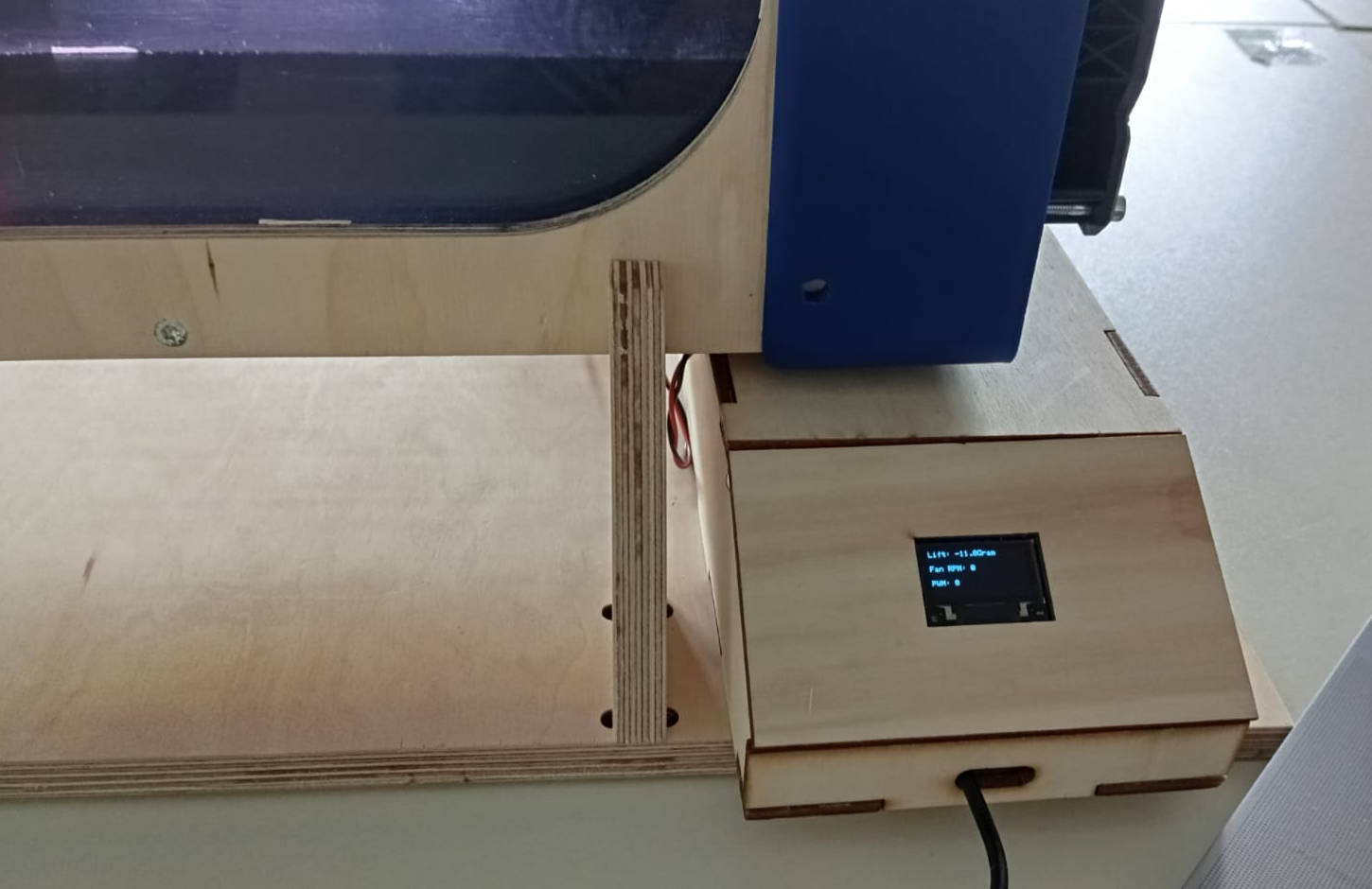
The load cell lets you see if an object has Lift or Down-force. Which is displayed on the OLED on the power box.The negative values
show force needed to create the down force. As for the positive values they show how much lift is being created by the object place on the load cell.
The Code
For this project the code has been created through out Fab Academy. It now needs to be pieced together. For the first time I considered
using chatgpt. But after a while of just not getting the code that made since to me, I gave up and went back to taking my time to
write the code the old fashioned way. I am willing to say that if you need explanations on how or why a certain code does not work, I find that
chatgpt is a nice tool, but nothing works better than leaning how to code by doing. So with the Chatgpt code not being my choice I went ahead and
stared with the simplest form.
To get the codes to work with each other I listed all the parts the that needed to be declared at the top from each of the codes. Naturally
Somethings need added and changed. One of the codes that stilled need to be created was for the Relay to control the
water vapour (smoke). To write this code I used the example code Blink form the IDE Library.
The blink example is one of the best examples that allows you to try different sensors out that have a times function that is similar to the
Built_in LED.
	// The following code can be used to turn on the module to create the water vapour smoke.
	// If an OlED is used  you can see if something is one or off. Please not that this code has 3 commands that
	// let you turn on & off the smoke as well as a interval that can be programmed to turn on and off automatically. ( time needs to be adjusted to liking in code)
	const int smokePin = 0; // GP0
	bool intervalMode = false;
	unsigned long interval = 1000;
	unsigned long lastToggle = 0;
	bool state = false;

	void setup() {
	  pinMode(smokePin, OUTPUT);
	  digitalWrite(smokePin, LOW); // Ensure it's off to start
	  Serial.begin(115200);
	  while (!Serial); // Wait for serial to connect (important for Pico W)
	  Serial.println("Ready for commands:");
	  Serial.println("  smoke on");
	  Serial.println("  smoke off");
	  Serial.println("  smoke interval ");
	}

	void loop() {
	  // Check for serial input
	  if (Serial.available()) {
		String cmd = Serial.readStringUntil('\n');
		cmd.trim(); // Remove whitespace and newline characters

		if (cmd == "smoke on") {
		  intervalMode = false;
		  digitalWrite(smokePin, HIGH);
		  Serial.println("Smoke ON");
		} else if (cmd == "smoke off") {
		  intervalMode = false;
		  digitalWrite(smokePin, LOW);
		  Serial.println("Smoke OFF");
		} else if (cmd.startsWith("smoke interval")) {
		  String intervalStr = cmd.substring(14); // Get number part
		  intervalStr.trim();
		  int val = intervalStr.toInt();
		  if (val > 0) {
			interval = val;
			intervalMode = true;
			Serial.print("Smoke interval set to ");
			Serial.print(interval);
			Serial.println(" ms");
		  } else {
			Serial.println("Invalid interval value.");
		  }
		} else {
		  Serial.println("Unknown command");
		}
	  }

	  // Handle interval mode toggling
	  if (intervalMode) {
		if (millis() - lastToggle >= interval) {
		  state = !state;
		  digitalWrite(smokePin, state ? HIGH : LOW);
		  lastToggle = millis();
		}
	  }
	}
The next code is final code if you were to run the tunnel just using the IDE as the main
interface. At this point the load cell is just shooting out random values. I am still trying to find a way to
have the load cell work with out calibration. This sounds easy but I am still trying to find a nicer looking solution.
For those who like to give this code a try or using a different load cell with a different weight class. I also added
the serial plotter, but I still have to get the load cell to and fan values to show up. This I hope I will have figured out
in the next couple of days.
At this time the relay is being controlled with the commands: Smoke On & Smoke Off, for the fan the commands:
Fan on & Fan Off as well as entering a value from 0-255. To test the tunnel the code below is okay. But refinements
are needed to have it function fully as an educational tool.
	#include
		#include
		#include
		#include "HX711.h"

		//  HX711 (Load Cell) Setup
		const int LOADCELL_DOUT_PIN = 18;
		const int LOADCELL_SCK_PIN = 19;
		const int Calibration_Weight = 5000;
		HX711 scale;
		bool calibrated = false;

		//  Fan Control Setup
		#define FAN_PWM_PIN 16
		#define FAN_TACH_PIN 2
		volatile int tachCounter = 0;
		unsigned long lastFanRead = 0;
		int rpm = 0;
		int fanSpeed = 255; // default full speed

		// Smoke Relay Control
		const int smokePin = 0; // GP0 for Smoke relay

		// OLED Display (I2C0 on GP4/GP5)
		#define SCREEN_WIDTH 128
		#define SCREEN_HEIGHT 64
		#define I2C_ADDRESS 0x3C
		Adafruit_SSD1306 display(SCREEN_WIDTH, SCREEN_HEIGHT, &Wire, -1);

		void tachInterrupt() {
		  tachCounter++;
		}

		void setup() {
		  pinMode(25, OUTPUT);  // onboard LED
		  digitalWrite(25, HIGH);

		  Serial.begin(115200);
		  delay(1000);
		  Serial.println("System Starting...");

		  //  Set I2C0 pins explicitly (GP4 SDA, GP5 SCL)
		  Wire.setSDA(4);
		  Wire.setSCL(5);
		  Wire.begin();

		  //  Initialize OLED
		  if (!display.begin(SSD1306_SWITCHCAPVCC, I2C_ADDRESS)) {
			Serial.println("OLED init failed");
			while (1) {
			  digitalWrite(25, !digitalRead(25));
			  delay(250);
			}
		  }

		  display.clearDisplay();
		  display.setTextSize(2);
		  display.setTextColor(WHITE);
		  display.setCursor(0, 20);
		  display.println("Booting Wind...");
		  display.display();
		  delay(2000);

		  // Load Cell Init
		  scale.begin(LOADCELL_DOUT_PIN, LOADCELL_SCK_PIN);
		  delay(2500);

		  //  Fan Init
		  pinMode(FAN_PWM_PIN, OUTPUT);
		  analogWrite(FAN_PWM_PIN, fanSpeed);

		  pinMode(FAN_TACH_PIN, INPUT_PULLUP);
		  attachInterrupt(digitalPinToInterrupt(FAN_TACH_PIN), tachInterrupt, FALLING);

		  // Smoke Relay Init
		  pinMode(smokePin, OUTPUT);
		  digitalWrite(smokePin, LOW); // Start OFF
		}

		void calibrateScale() {
		  Serial.println("Starting calibration...");
		  scale.set_scale();
		  scale.tare();

		  Serial.println("Place known weight...");
		  delay(5000);

		  float raw = scale.get_units(10);
		  float scaleFactor = raw / Calibration_Weight;
		  scale.set_scale(scaleFactor);

		  Serial.println("Calibration done.");
		  calibrated = true;
		}

		void loop() {
		  //  First-time Calibration
		  if (!calibrated) {
			calibrateScale();
		  }

		  //  Fan and Smoke Serial Control
		  if (Serial.available()) {
			String cmd = Serial.readStringUntil('\n');
			cmd.trim();

			if (cmd.equalsIgnoreCase("ON")) {
			  fanSpeed = 255;
			} else if (cmd.equalsIgnoreCase("OFF")) {
			  fanSpeed = 0;
			} else if (cmd.equalsIgnoreCase("smoke on")) {
			  digitalWrite(smokePin, HIGH);
			  Serial.println("Smoke ON");
			} else if (cmd.equalsIgnoreCase("smoke off")) {
			  digitalWrite(smokePin, LOW);
			  Serial.println("Smoke OFF");
			} else {
			  int val = cmd.toInt();
			  if (val >= 0 && val <= 255) {
				fanSpeed = val;
			  }
			}
		  }

		  analogWrite(FAN_PWM_PIN, fanSpeed);

		  //  Read Fan RPM every second
		  unsigned long now = millis();
		  if (now - lastFanRead >= 1000) {
			lastFanRead = now;
			rpm = (tachCounter / 2) * 60;
			tachCounter = 0;
		  }

		  // Read Load Cell
		  float force = 0;
		  if (scale.is_ready()) {
			force = scale.get_units(5);
		  }

		  //  Display on OLED
		  display.clearDisplay();
		  display.setTextSize(1);
		  display.setCursor(0, 0);
		  display.print("Lift/Down: ");
		  display.print(force, 1);
		  display.println(" g");

		  display.setCursor(0, 20);
		  display.print("Fan RPM: ");
		  display.println(rpm);

		  display.setCursor(0, 40);
		  display.print("PWM: ");
		  display.println((fanSpeed / 255.0) * 100, 0); // percent
		  display.print("%");

		  display.display();

		  //  Serial Plotter Output
		  Serial.print("Lift(g): ");
		  Serial.print(force);
		  Serial.print("\tRPM: ");
		  Serial.println(rpm);

		  delay(250); // smooth updates
		}
running the tunnel
When running the electrical components the first time, only use the power proved by the usb to the PCB. If all systems seem to run on command, the next step here was to plug in the main power and let the system boot. Once the tunnel is powered, plug in the laptop with the IDE open. Run the same test as before: Fan "ON" & "OFF" and "Smoke ON & Smoke OFF" If nothing is connected wrongly, the fan should be on as a default mode and the smoke should be off. The rest should be the load cell which will display itself as random numbers without any calibration.
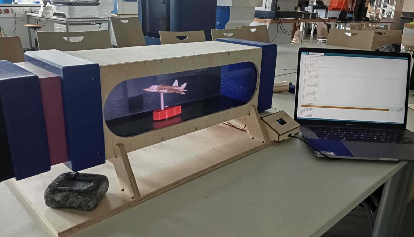
Trying to find Laminar Flow
One of the more interesting parts of the tunnel is the observation of flow. This may seem to be the easiest sounding part to figure
out, it is not. Running the PC Fan at full speed, will accelerate the water vapour so much that it
flows funny. This is do to the fact, the piezos modules are already creating frequency rate at which the water
is being shot out into the Air-strainer. Meaning that it is creating turbulence's that cause the laminar flow in the tunnel to fall
apart. To correct this issue, the piezos need to move back as far as they can. The basic idea still works with out a full redesign,
this is a okay result for the time being. What you really want to have happen is that thought the Vacuum in the tunnel
itself to pull in the "smoke". This keeps all the turbulence's out of the tunnel, giving a clean laminar flow.
This took some time to get dialed in. Playing with the speeds of the fan to find what works best. This meant that decreasing
the fans speeds in small steps and waiting to see what the visual result was. I started at 255 PWM which is the maximum speed the
fan can produce. Having found the right speed at a PWM of 122 to 127, which is just under the
50% mark of the fans maximum top speed. The reason that the speed needs to decrease has with two factors, one you want a low Reynolds Numbers
avoids turbulence. Secondly the water vapour would dissipate to a point that a visual confirmation of laminar flow could not be
confirmed.
How you can find out of you do have laminar flow is by placing very light strings through out the tunnel or even on the objects
themselves. Or if you are going the water vapour path, over smoke and dry ice, let the water vapour fill tunnel, than turn on the fan
to full blast. If done right you will see all the water vapour partials form a straight line and accelerate out of the tunnel through
the fan.
Having tried out multiple different configurations out, the following can be seen as a success. The tunnel is able to pull the water vapour
over different objects that show what happens when air flows over a surface. Even when the flow was less than optimal the turbulence made by
the subject placed in the tunnel showed interesting results.
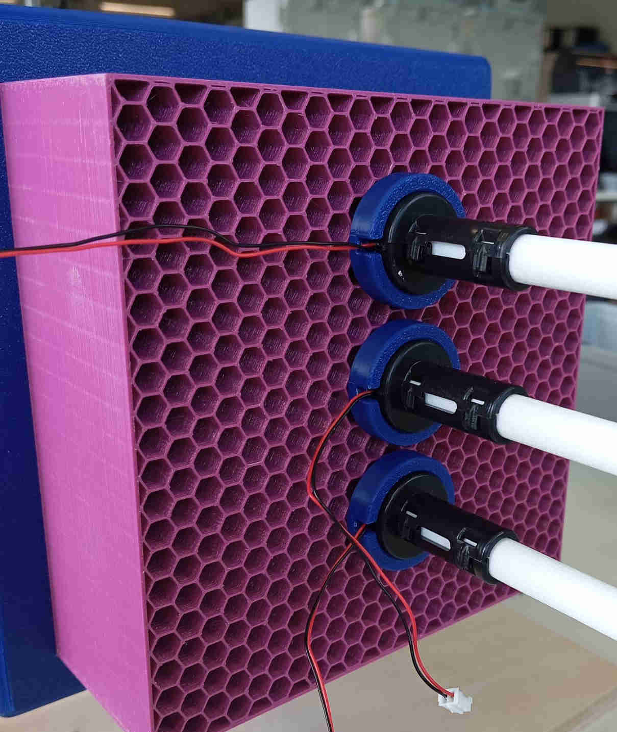
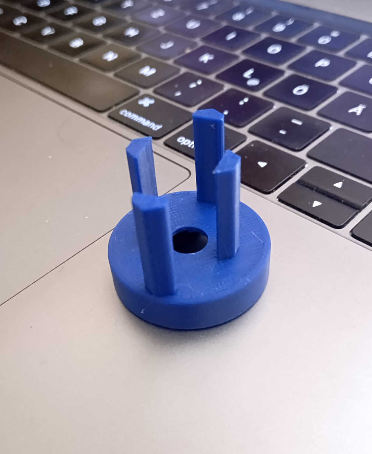
In oder to have the vapour enter the tunnel a small part was created that is placed alone the Air-strainer. This part can be placed where it is needed.
The module is placed in the the 3D printed part and is held in place with with friction. The minimal distance for placing the piezos to the air-strainer is
at 8mm. The further away the piezos are placed the better. This is because you do not want the vaporize water to be shot into the tunnel, as this will create
turbulence's. The vapour needs to be pulled in under the vacuum formed by the tunnel. This design currently works but not as good as it should. The current
design is experimental. As the results of this the next version is undergoing a complete redesign. The car in the video below was downloaded
from thingiverse. Originally someone else had 3D printed the car and I just happen to reprint it. I later on found it on the
webpage above.
This was the first object that was placed in the tunnel. It is clearly shows that the box like shaped car is creating turbulent drag at the back of the car. Other object like the an airplanes nose cone and a bionics inspired birds beak show how the drag is reduced.
Load cell
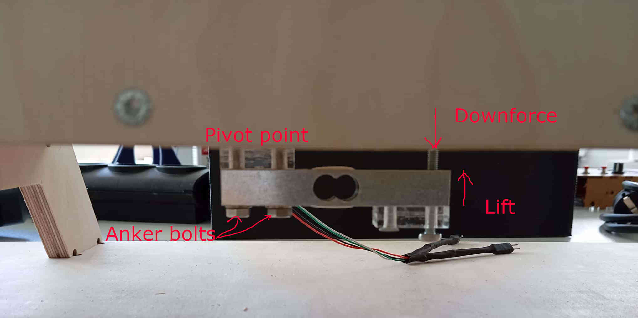
To find if an object is creating down force or lift, the use of a load cell will help. The load cell is connected at the bottom of the
the tunnel and is bolted on with cut threads in the plywood. This holds and can be tighten down. Use caution when doing so, as once the bold are tight,
the chance of over tighten and stripping the threads in the wood. On the of side of the load cell a small threaded rod is added and a hole is drilled out
to let the threaded rod into the tunnel. The threaded rod allows you to place an object on it. To use the load cell, it must be calibrated first.
Calibration
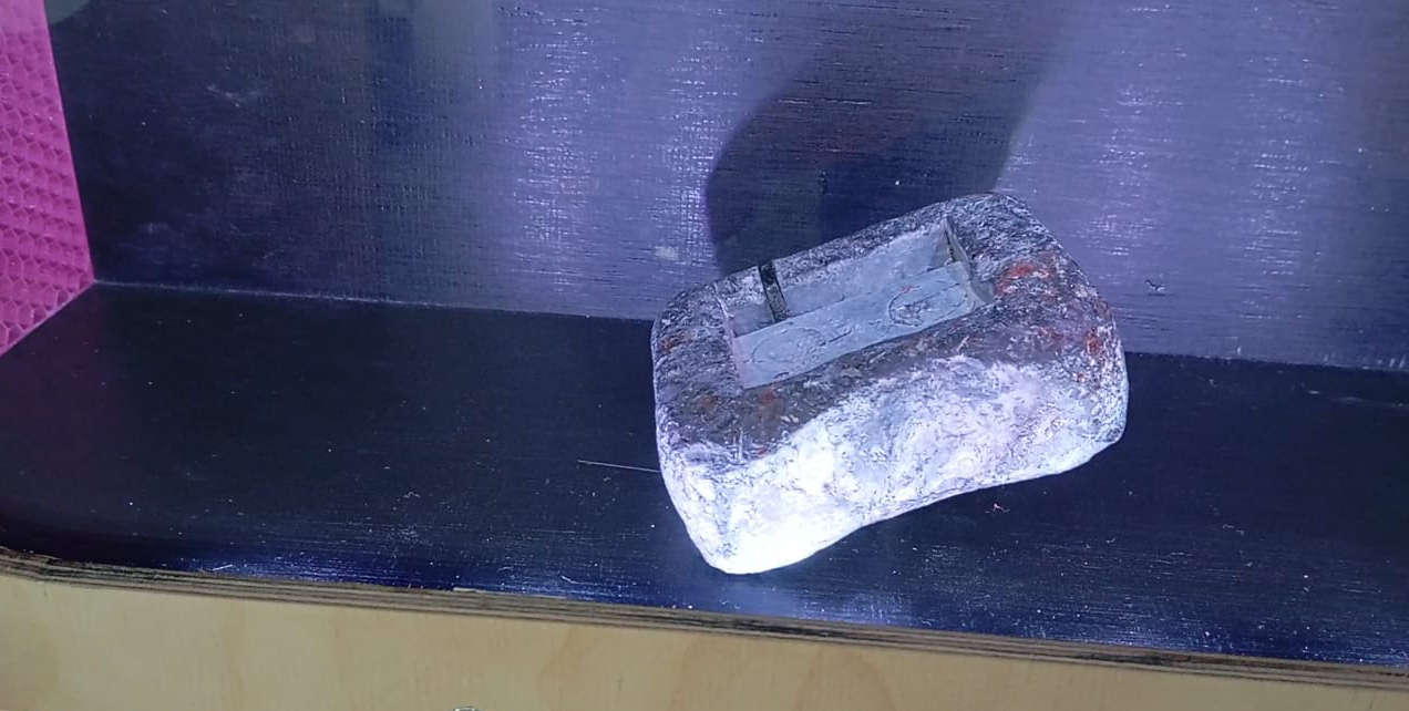
To calibrate the load cell the use of a known weight must be placed on the threaded rod. In the case of this particular load cell, which can take a load of 10kg.
In the tunnel itself there is no room to be able to place a full 5kg weight let alone a 10kg weight. The use of diving lead works just as well. Placing the
known weight, here 2kg, on the threaded rod. Once the calibration is done the weight can be removed. To learn more about how the load cell works and the problems
that I can in to the link above will lead you to the assignments about input devices.
It was not easy to really get good readings without having a wing to place on the load cell. Instead a small jet fighter model was placed on the threaded rod once
the calibration mentioned earlier was done.
The video shows a not impressive value of 1 Gram of force when the fan is at 100% power and as mentioned before this was not a model meant for creating down force or lift. The load cell is sensitive enough to notice small changes. Later on I hope to have time to create a some bionic inspired wings that will show how much lift or down force the wings have. In the video the fan speed is at first at 122 PWM, here little to no change can noticed. After the fan is set to 255 PWM the result 1 gram. As to why the Values are negative and not at zero has to do with the scale being off. This can be due to an issue of the HX711 receiving noisy signals. The load cell is set up to have a positive value when down force is present and a negative value for lift.
OLED display screen
On the power supply box I have added a OLED display that shows what the current PWM speed, force that the Load cell is experiencing. The OLED used
I2C functions which are explained in networking & communications. This helps as some code is not displayed on the IDE's Serial Monitor.
The OLED also displays if tunnel is loading when first starting up. It is nice addition that gives back live feed back. As shown in the video above.
interface GUI
The OLED display is a nice part but it is missing the functionality of interaction. To have an interface is ideal for the wind tunnel, this
give you more control with a single click of the mouse. Currently the tunnel runs with commands typed into the serial Monitor of the IDE. This slow in comparison with being
able to click a button to turn things off like the smoke and the fan. Even letting you control the fans speeds. The code for the interface was created with processing.
There are many different examples that can be found online on how to create each of the elements and how to link there function to the IDE codes. Youtube was my main source for
a lot of the different issues I ran into along the way. For more on how to get stared use the link interface. The interface at the moment is very simple and in the future I hope to have
other functions such as graphs to show minimal forces and ratios that can be compared to airspeeds in the tunnel.
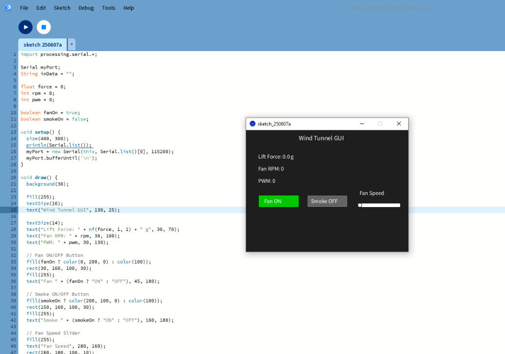
Interface code
	import processing.serial.*;

Serial myPort;
String inData = "";

float force = 0;
int rpm = 0;
int pwm = 0;

boolean fanOn = true;
boolean smokeOn = false;

void setup() {
  size(400, 300);
  println(Serial.list());
  myPort = new Serial(this, Serial.list()[0], 115200);
  myPort.bufferUntil('\n');
}

void draw() {
  background(30);

  fill(255);
  textSize(16);
  text("Wind Tunnel GUI", 130, 25);

  textSize(14);
  text("Lift Force: " + nf(force, 1, 1) + " g", 30, 70);
  text("Fan RPM: " + rpm, 30, 100);
  text("PWM: " + pwm, 30, 130);

  // Fan ON/OFF Button
  fill(fanOn ? color(0, 200, 0) : color(100));
  rect(30, 160, 100, 30);
  fill(255);
  text("Fan " + (fanOn ? "ON" : "OFF"), 45, 180);

  // Smoke ON/OFF Button
  fill(smokeOn ? color(200, 100, 0) : color(100));
  rect(150, 160, 100, 30);
  fill(255);
  text("Smoke " + (smokeOn ? "ON" : "OFF"), 160, 180);

  // Fan Speed Slider
  fill(255);
  text("Fan Speed", 280, 160);
  rect(280, 180, 100, 10);
  fill(0, 150, 255);
  rect(280, 180, map(pwm, 0, 255, 0, 100), 10);
  fill(255);
  ellipse(map(pwm, 0, 255, 280, 380), 185, 10, 10);
}

void mousePressed() {
  // Fan Button
  if (mouseX > 30 && mouseX < 130 && mouseY > 160 && mouseY < 190) {
    fanOn = !fanOn;
    myPort.write(fanOn ? "ON\n" : "OFF\n");
  }

  // Smoke Button
  if (mouseX > 150 && mouseX < 250 && mouseY > 160 && mouseY < 190) {
    smokeOn = !smokeOn;
    myPort.write(smokeOn ? "smoke on\n" : "smoke off\n");
  }

  // Slider control
  if (mouseX > 280 && mouseX < 380 && mouseY > 175 && mouseY < 195) {
    pwm = int(map(mouseX, 280, 380, 0, 255));
    fanOn = pwm > 0;
    myPort.write(pwm + "\n");
  }
}

void serialEvent(Serial p) {
  inData = trim(p.readStringUntil('\n'));
  if (inData.startsWith("FORCE:")) {
    String[] parts = splitTokens(inData, ":,");
    if (parts.length == 6) {
      force = float(parts[1]);
      rpm = int(parts[3]);
      pwm = int(parts[5]);
    }
  }
}
How much did the overall cost
The over all build was a fun adventure. The Cad design using fusion was a overall easy experience. All the cad files can be downloaded below. Fusion is easy to use and very intuitive once you get used to using the software. I did not count fusion into the cost, as you can get a 30 day trail or if you are a register students the software is free. Many of the electoral parts I received from Fab lab kamp-lintfort Using KiCAD made it easy to find all the prices for the PCB build. The next part of the build involved the use of the 3D printer as many parts like the honeycomb Air-strainer, Intake and many of the other connecting parts. This was about 4kg of PLA filament. Some of the these parts could be made with other material like plywood. Even the air-strainer could be made with the use of a laser cutter. The man testing section of the the tunnel was made with a CNC. The uss of the CNC was a nice option, but a table saw and a router could easily do the the same job. The total costs of all the parts included are listed below. To find out more about the materials and other questions go to applications and implications, project development.
3D Printed Parts (PLA)
| Part | Cost (€) |
|---|---|
| Air Intake | 23.00 |
| Air-Strainer | 18.36 |
| Intake-Strainer Connection | 11.13 |
| Strainer-Tunnel Connection | 3.91 |
| Air Backflow Filter | 4.72 |
| Fan Diffuser | 4.10 |
| Total PLA Cost | €65.22 |
Wood Parts
| Part | Cost (€) |
|---|---|
| Tunnel + Stand (12mm Plywood) | 10.00 |
| Electrical Housing (4mm Plywood) | 6.75 |
| Total Wood Cost | €16.75 |
PCB Electronic Components
| Description | Total (€) |
|---|---|
| Capacitors, Headers, LED, Resistor, PCB, Pico W, Regulator | 16.63 |
| Total PCB Component Cost | €16.63 |
Other Electrical Components
| Component | Cost (€) |
|---|---|
| 12V Power Supply (LRS-35-15) | 10.78 |
| Main Power Switch (1/10 pack) | 0.69 |
| Load Cell | 5.75 |
| Humidifier Module | 7.50 |
| 12V LED Lights | 10.40 |
| 120mm PC Fan | 14.90 |
| Total Other Electrical Cost | €50.02 |
Grand Total
| Category | Cost (€) |
|---|---|
| 3D Printed Parts (PLA) | €65.22 |
| Wood Parts | €16.75 |
| PCB Components | €16.63 |
| Other Electrical Components | €50.02 |
| Total Project Cost | €148.62 |
Hero shots
future ideas and ideas
There are many things about this wind tunnel that could use some engineering and experimentation. The tunnel works good, but as this is
a working prototype and I am still experimenting currently with different settings and different ideas on how to solve simple issues
such as the water vapour causing turbulence in the testing section that are unwanted. How does would a vacuum work and look like to pull the
water vapour into the tunnel. Getting the load cell to work better, how could a single load cell show values for drag and lift/down force?
There are many questions that I have listed just in the last couple of days. Many of these answers will still have to be found under some
research with more time.
What does the Tunnel do?
A wind tunnel works in different ways. The configuration for this wind tunnel works on the concept air enters the Intake, which has an area 4 times
larger than the cross-sectional area of the testing tunnel. With the help of bernoulli's principle which states in order to
increase the speed of a fluid the area that the fluid flows through must decrease and increase to slow the flow of the fluid down. The intake
decreases to the cross-sectional area of the tunnel, while compressing the air and which increases the speed at which the air travels. Once the air has
sped up, it moves through a air-strainer with a honeycomb like structure. This structure can have many different shapes but the one part that matters
the most is the length. Which an be calculate and is mentioned up top under the title: the math. The length is important because it
straightens the air flow out. The more filter with finer and finer meshes you add the more laminar the flow will get.
The reason we want to have laminar flow, is that when air flows in a straight line we can easily see areas that can could issues with drag. This is what
this tunnel does, it shows objects in movement without them moving through the air. These allows for small models to be built and tested where as if
you wanted to test car or airplane you used to have to build the real deal and test and adjust the actual project. The wind tunnel allows you to do
the same and save time and money. To most of this type of engineering is done through CAD software that have algorithms that will tell you
where problem areas are. This tunnel is mainly for the visual confirmation and teaching in class room settings.
In the future I would like to change the air strainer, add different types of mesh and screens, maybe look into multiple fans and a better interface
which would allow to save data and over lay reading of the sensors on graphs and save them to be able to analysis. I would also like to add a door of some
type to alow easier access to place objects in the tunnel without having to remove the fan ever time. Also making a smoother intake as the
3D printed one is rather rough.
There are many things I would like to try, and the list keeps growing. For now the tunnel will be used to demo how different objects move through the
air, to stem students. I wanted this tunnel to fit on a desk, to fit in a car, and be easy to move around. Not to mention having laminar flow. All these
goals were met and they will be improved even after Fab Academy. One goal is still be keep improving tunnel and learn from how flow works which can only be
done by the power of observation.