04 Assignment (Embedded Programming)

This week's assignment is all about embedded programming. What is embedded programming? Embedded programming is code written and stored on a microcontroller. You probably have one near you right now, like in your Bluetooth mouse! The microcontroller inside has a set of instructions that tell it what to do when you move it or click a button. Microcontrollers are perfect for small tasks, like turning on your Bluetooth headset or controlling appliances. In contrast, your computer uses a different system because it needs to run multiple programs at once. There are many different types of microcontrollers, and we compared them in our group assignment to see what the main differences are.

This weeks to-do list

  • Read data sheet

  • program using a simulator

  • explain your code


  • Intro to the Arduino R3

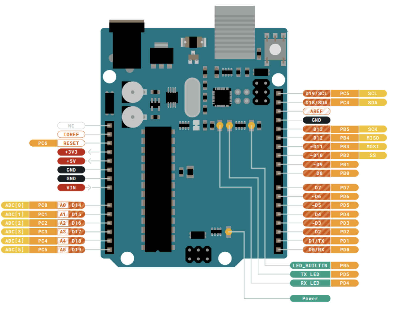
    The Arduino Uno R3 is a very popular microcontroller board, based on the ATmega328P chip. 
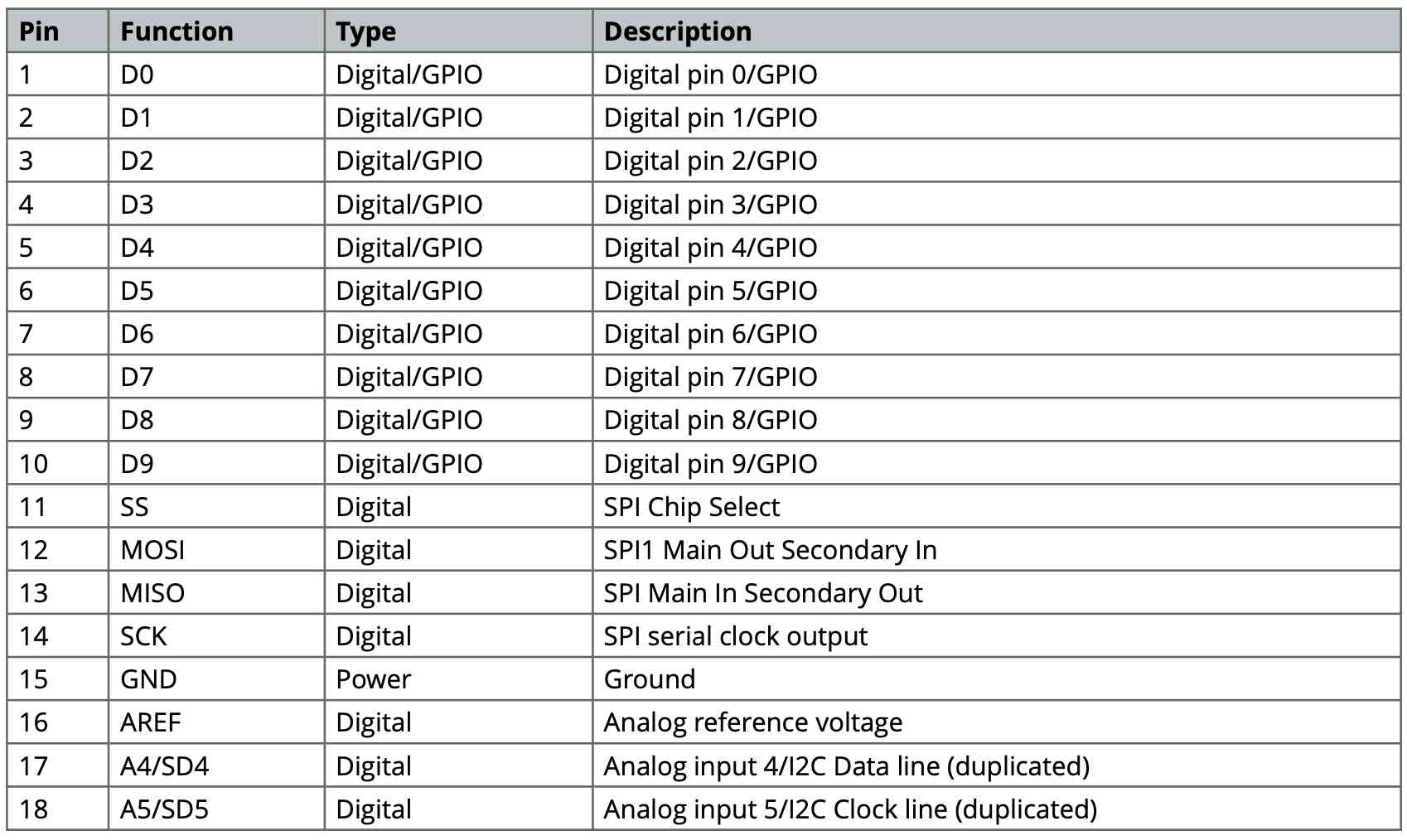
It features 14 digital input and output pins, six of which can be used as PWM outputs, six analog inputs, a USB connection that can be used for programming the board, and a power jack—not to mention a reset button. The Arduino Uno R3 can be powered by either USB or an external power supply. The ATmega328P is an 8-bit microcontroller and is part of the AVR family, making it optimized for low power consumption and high performance.

    features

  • 8-bit Reduced Instruction Set Computing
  • Clock Speed: Up to 16 MHz
  • Flash Memory: 32 KB
  • SRAM: 2 KB (for variables and runtime memory)
  • EEPROM: 1 KB (for non-volatile storage)
  • I/O Pins: 23 general-purpose input/output (GPIO) pins
  • 6 PWM Channels
  • UART, SPI, and I²C for serial communication
  • built in LED

  • For more in formation here is a link to the Data sheet.
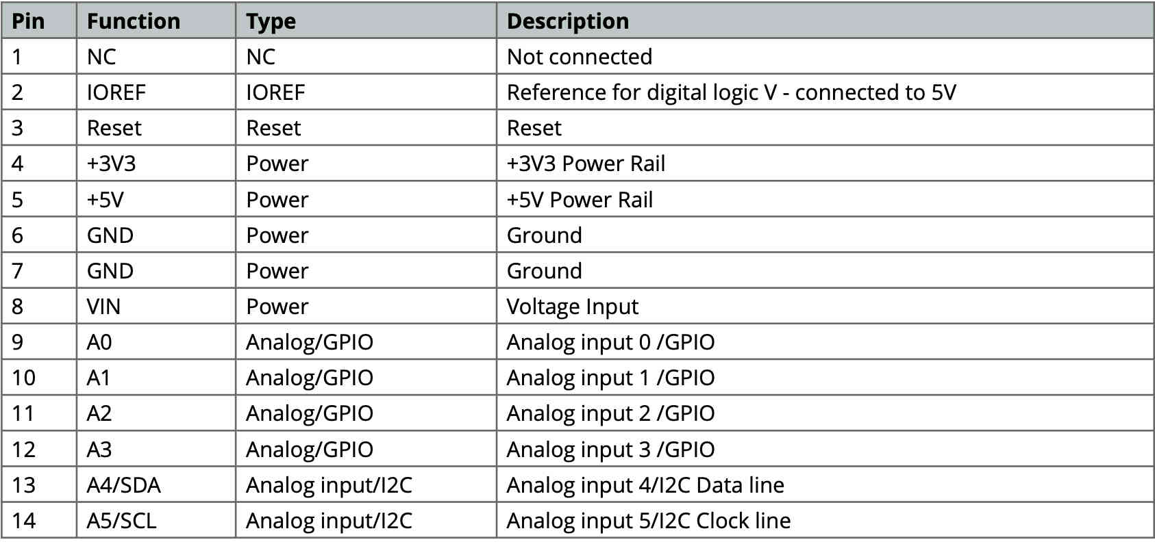
    How the R3 is setup


    The boards itself is labeled giving you a hint on which pin you are using. Including the Grounds, 5 Volt and 3.3 Volt pins.

    Simulator for embedded coding

    After experimenting with both Tinkercad and Wokwi simulators on different boards, I decided to stick with Tinkercad. It was easy to learn, and I could reuse the code I had previously worked with on other Arduino projects. I’m by no means an expert in programming, but from my past classes, I have a general understanding of what I’m looking for. My main skill set is in mechanics and design. The first thing I did was repeat simple code examples that were easy to understand, such as blinking an LED, a stoplight simulation, and using an ultrasonic sensor. However, getting a motor to turn on was a challenge. I started by building a circuit I knew would work: an LED that turns on when I press a button. This gave me a great starting point, allowing me to later add an external power source to run the motor. It’s important to remember that an LED has a positive (anode) and a negative (cathode) side. If you want a good introduction to how to use Tinkercad with Arduino and some great examples to work with, check out these videos.

    The Simple circuit

    To change the circuit to work with a motor I added a Mosfet N-channel and an external power source. This gave me the chance to keep the same code, for both codes.
    
    										// Define pin numbers
    										const int LEDpin = 9;
    										const int butpin = 2;
    										int state;
    										
    										void setup() {
    										  // Set pin modes
    										  pinMode(LEDpin, OUTPUT);
    										  pinMode(butpin, INPUT_PULLUP); // Corrected from 'Input_push'
    										}
    										
    										void loop() {
    										  // Read button state
    										  state = digitalRead(butpin);
    										
    										  // If button is pressed (LOW because of INPUT_PULLUP)
    										  if (state == LOW) { 
    											digitalWrite(LEDpin, LOW);
    										  } 
    										  else {
    											digitalWrite(LEDpin, HIGH);
    										  }
    										}


    The code I wrote

    The code is simple to understand. The first step is deciding which pins to use—in this case, pin 9 for the LED and pin 2 for the button. The pinMode() function tells the Arduino which pins will be used and how they should behave. The syntax is:
    The syntax is:

  • pinMode(9, OUTPUT); sets pin 9 as an output for the LED.
  • pinMode(2, INPUT); sets pin 2 as an input for the button.

  • Modes:

  • INPUT – Configures the pin to read signals (e.g., from a button or sensor)
  • OUTPUT – Configures the pin to send signals (e.g., to turn on an LED or motor)
  • INPUT_PULLUP – Enables an internal pull-up resistor, useful for buttons and switches


  • In the loop, I added an if-else statement, creating a state that repeats continuously, comparing whether the button is pushed or not. Here, the microcontroller checks for a HIGH or LOW state, telling it whether something is on or off.

    
    										// Define pin numbers
    										const int LEDpin = 9;
    										const int butpin = 2;
    										int state;
    										
    										void setup() {
    										  // Set pin modes
    										  pinMode(LEDpin, OUTPUT);
    										  pinMode(butpin, INPUT_PULLUP); // Corrected from 'Input_push'
    										}
    										
    										void loop() {
    										  // Read button state
    										  state = digitalRead(butpin);
    										
    										  // If button is pressed (LOW because of INPUT_PULLUP)
    										  if (state == LOW) { 
    											digitalWrite(LEDpin, LOW);
    										  } 
    										  else {
    											digitalWrite(LEDpin, HIGH);
    										  }
    										}
    										

    Attempting to control a motor with arduino

    In order to control a motor with Arduino, it is very important to be aware that a DC motor will need more power than the board can provide. When adding an external power source, I made sure that it did not short out the board, as this could easily destroy it. The board can share a common ground with the external power source, but the positive lead needs to be disconnected from anything that leads back to the board. To control the motor, I needed to add a MOSFET and a potentiometer, which can be described as a variable resistor. Since I did not fully understand what a MOSFET is or what it does, I looked up the datasheet for the MOSFET. Next, I added a breadboard, which is a board where you can connect different electronic components. After trying many different configurations, I turned to YouTube to figure out what I was doing wrong with my setups.


    After getting the setup right and writing a little code I came up the following.


    									// defining my pins and names
    									const int motorpin=9;
    									const int potpin=A0;
    									int pot;
    									int speed;
    									
    									void setup(){
    									  // do not need code here
    									  // just need a signla form the PWM on the board
    									  // main control is over the Potentiometer
    									  
    									}
    									
    									void loop(){
    									  pot = analogRead(potpin);
    									  speed = map(pot,0,1023,0,255);
    									  analogWrite(motorpin,speed);
    									  }