10 - Output devices
As explained in the group assignment output device is basic information that a computer or micro-controller can display in a form of data
that we can understand. So using the PCB form the final project featuring a Pi Pico W will power a fan on and off and even have a look at the Tachometer
read out. In assignment 08, Electronics Production we all made a PCB. Here It was already clear that controlling the PC fan was necessary. It will also
include the use of a screen either LCD or OLED. It will later have to also power LED lights to back light the tunnel. These are all output devices.
Looking at the fan for example, if the command "ON" is given, the output of that is the fan blades start to rotate, this is the output that we were looking for.
Same thing should happen when the command "OFF" is given. In the group assignment we used the built-in function to relay the fan to turn on and off at specific
time intervals. What is now important to be able to tell the fan what power setting we want it tun at. This important for running any test that would give us
conclusive data that would be useful. At this point the wiring of the fan is important. The fan is corsair
120mm diameter, 12volt, 0.295Amps and a max of 2400rpm. This great information but it does not tell me how mich air the fan is moving. I did search for
data-sheet and came up blank. This were I will do a little math. PC fans even in Europe are mostly sold with a Cubic Feet per Minute. I do find this a
little funny as the fan is sold with metric dimensions.
The math is simple: CFM = (RPM x Diameter^2)/constant. Converting 120mm in to inches and we get 4.72 inches.
At full power the fan should have CFM = (2400 x 4.75in^2)/150 = 356.45 CFM. The 356 CFM are equal to a maximum air flow of 606 cubic meter pre hour.
Just to put that into perspective that is about 10 meter cubed in one min. How did I choose my constant? As I know nothing about fan blade design I looked up the
most commonly used constants and found that between 150 to 200, depending on fan blade design. But I am have gone completely of topic and need to return to the
programming at hand for the output devices.
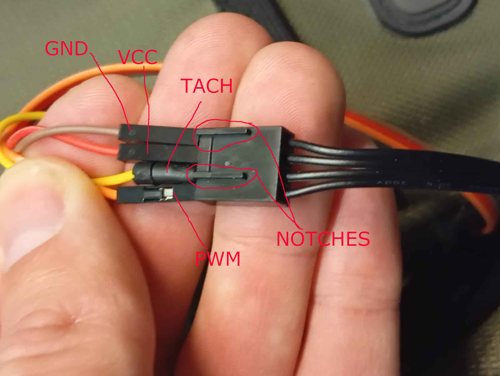
Looking at he plug that PC fan has and noticing that the fan has 4 wires, all black. This gave me no indication what wire does what. A quick google search for
pc fan plugs shows me which wire was what. Looking at the connection we can tell that we have notches that help in telling which wire is for VCC, GND, Tachometer,
and PWM. Looking at the photo we can see that the Strong GND is on the outside with where the outer notch is located. The VCC is next followed by the Tach and the
PWM.

writing the code
The Tach short for tachometer is really not needed. As I find it to be important to find out if the the fan will come close to the given specs of 12V at 0.295Amps
with round about 2400 RPM I will set up the pin so that preset speeds can be used for the flow when testing it the tunnel. This means that Tach
needs another pin to wire up to, as that on the first version of the board the pin is just for show. But this may change in the next version of the PCB. For now lets
call this pin GPIO 1. Which is the second pin if you check that data-sheet. What I find helps me is to write down the pins that will be used before
writing any code. This allows you to define the pins first thing and if any other pins need to be defined they can be added easily at the top of the code.
Next I try to list all the things that will need to be part of the programming code. It help insure that nothing gets left out and over increase of efficiency.
I need to find out what the RMP are. RPMs are the Rotations per Minute. Now depending on the fan these can be 2 measurements or 4 measurements per minute.
This easy to recognize if the speed displayed in the serial monitor looks to low or to high. Looking over the code below is a description telling what parts do what.
Here I have to admit that I used a AI to help me find the right commands. This is faster than looking at codes that everyone has posted and also helped me understand
the context of what these new commands mean. I do recommend to write as much of the code yourself as it is a good basic skill to have now days.
	#define FAN_PWM_PIN 16
int fanSpeed = 0;  // Default OFF

void setup() {
  Serial.begin(115200);
  pinMode(FAN_PWM_PIN, OUTPUT);
  analogWrite(FAN_PWM_PIN, fanSpeed);

  Serial.println("Type 'ON' to start the fan or 'OFF' to stop it.");
}

void loop() {
  if (Serial.available()) {
    String command = Serial.readStringUntil('\n');
    command.trim();

    if (command.equalsIgnoreCase("ON")) {
      fanSpeed = 255;
      Serial.println("Fan is running.");
    }
    else if (command.equalsIgnoreCase("OFF")) {
      fanSpeed = 0;
      Serial.println("Fan is OFF.");
    }
    else {
      Serial.println("Invalid command. Type 'ON' or 'OFF'.");
    }

    analogWrite(FAN_PWM_PIN, fanSpeed);
  }
}
The code above let me set the fan to different speeds and also let me find the RPM and verified that the fan was spinning that the RMPs found in the description.
This was great news to find out. Now that we kow the top speeds that the fan can produce. This was nice as meant the low flow tunnel will work. Next was getting
code that allowed different flow setting (fan speeds). As the speeds are set to magnetic pulses the max being 255. These made picking different power setting
easy. There are two different ways of doing this. First thing was finding the value that would just make the fan rotate, this was 60 pulses. Lets call this
20% power and 255 pules 100%. Now by know the values lets us preset values that we wan to use. This would be the second option that I am considering using in the
final project. This way there are preset functions with a single push of a button. For now the simpler the code the better for such fas development.
In the code below I stuck to the values of the pulses. Using the serial monitor where not just the RMP are displayed, it also allows to enter values to adjust the
fans speed.
	#define FAN_PWM_PIN 16
	#define FAN_TACH_PIN 2

	volatile int tachCounter = 0;
	unsigned long lastTime = 0;
	int rpm = 0;
	int fanSpeed = 255;  // Default full speed

	void tachInterrupt() {
	  tachCounter++;
	}

	void setup() {
	  Serial.begin(115200);
	  Serial.println("Enter a speed (0-255) or type 'ON'/'OFF'.");

	  pinMode(FAN_PWM_PIN, OUTPUT);
	  analogWrite(FAN_PWM_PIN, fanSpeed);

	  pinMode(FAN_TACH_PIN, INPUT_PULLUP);
	  attachInterrupt(digitalPinToInterrupt(FAN_TACH_PIN), tachInterrupt, FALLING);
	}

	void loop() {
	  // **Serial Input Handling**
	  if (Serial.available()) {
		String command = Serial.readStringUntil('\n');
		command.trim();

		if (command.equalsIgnoreCase("ON")) {
		  fanSpeed = 255;
		  Serial.println("Fan turned ON at full speed.");
		}
		else if (command.equalsIgnoreCase("OFF")) {
		  fanSpeed = 0;
		  Serial.println("Fan turned OFF.");
		}
		else {
		  int speedValue = command.toInt();  // Convert input to integer
		  if (speedValue >= 0 && speedValue <= 255) {
			fanSpeed = speedValue;
			Serial.print("Fan speed set to: ");
			Serial.println(fanSpeed);
		  }
		  else {
			Serial.println("Invalid input! Enter 'ON', 'OFF', or a number (0-255).");
		  }
		}
	  }

	  // **Set Fan Speed**
	  analogWrite(FAN_PWM_PIN, fanSpeed);

	  // **RPM Measurement (every second)**
	  unsigned long currentTime = millis();
	  if (currentTime - lastTime >= 1000) {
		lastTime = currentTime;

		rpm = (tachCounter / 2) * 60;
		tachCounter = 0;

		Serial.print("Fan RPM: ");
		Serial.println(rpm);
	  }
	}
Screen shot and hero video short
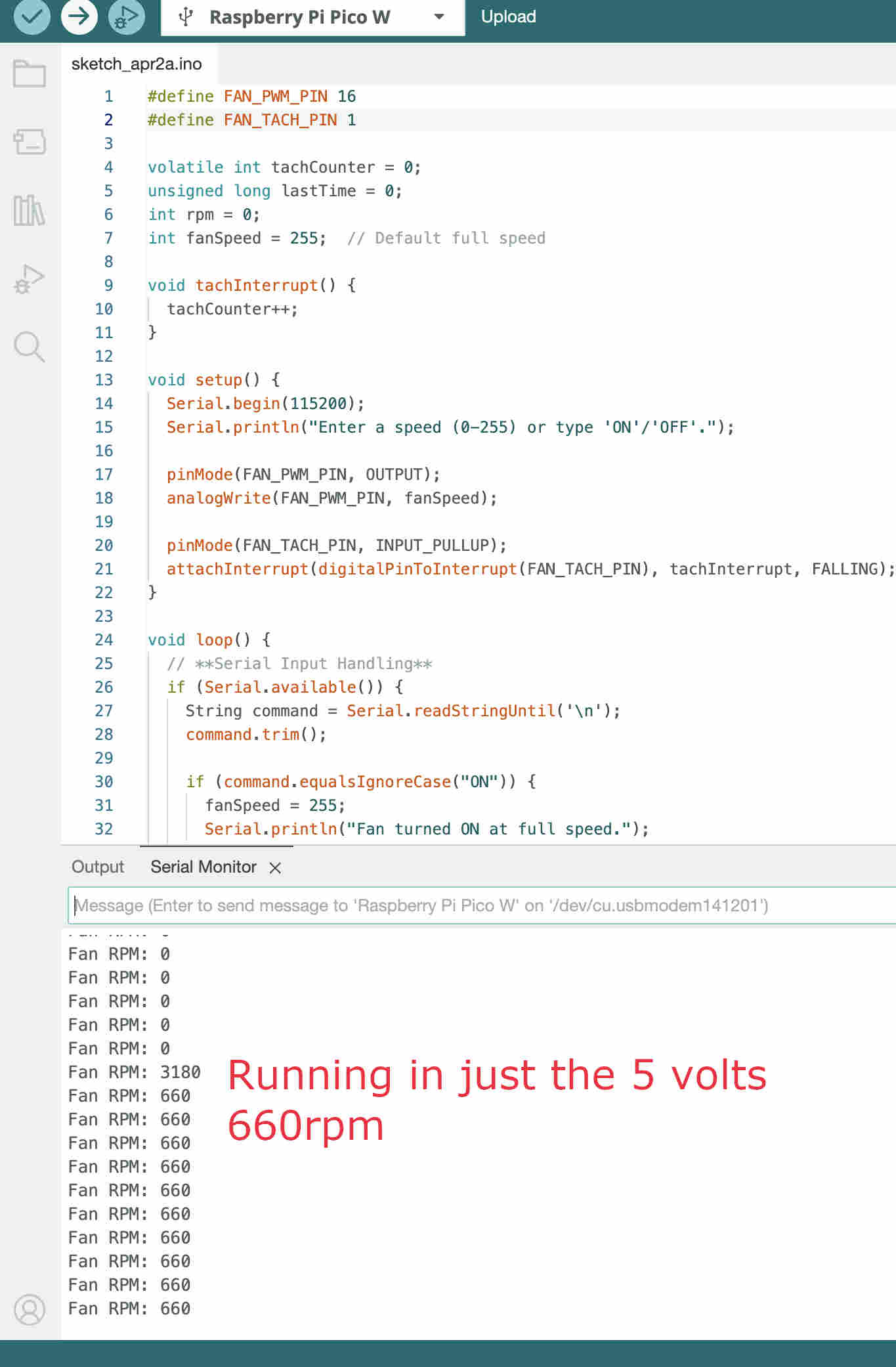
Below I am proud to show off the success of having been able to get the fans find out at what pulse the pc fans runs at and the fact that is ran over my PBC board. Here are the screen shots of the fan just running on 5 volts provided by the USB to the RP Pi Pico W.

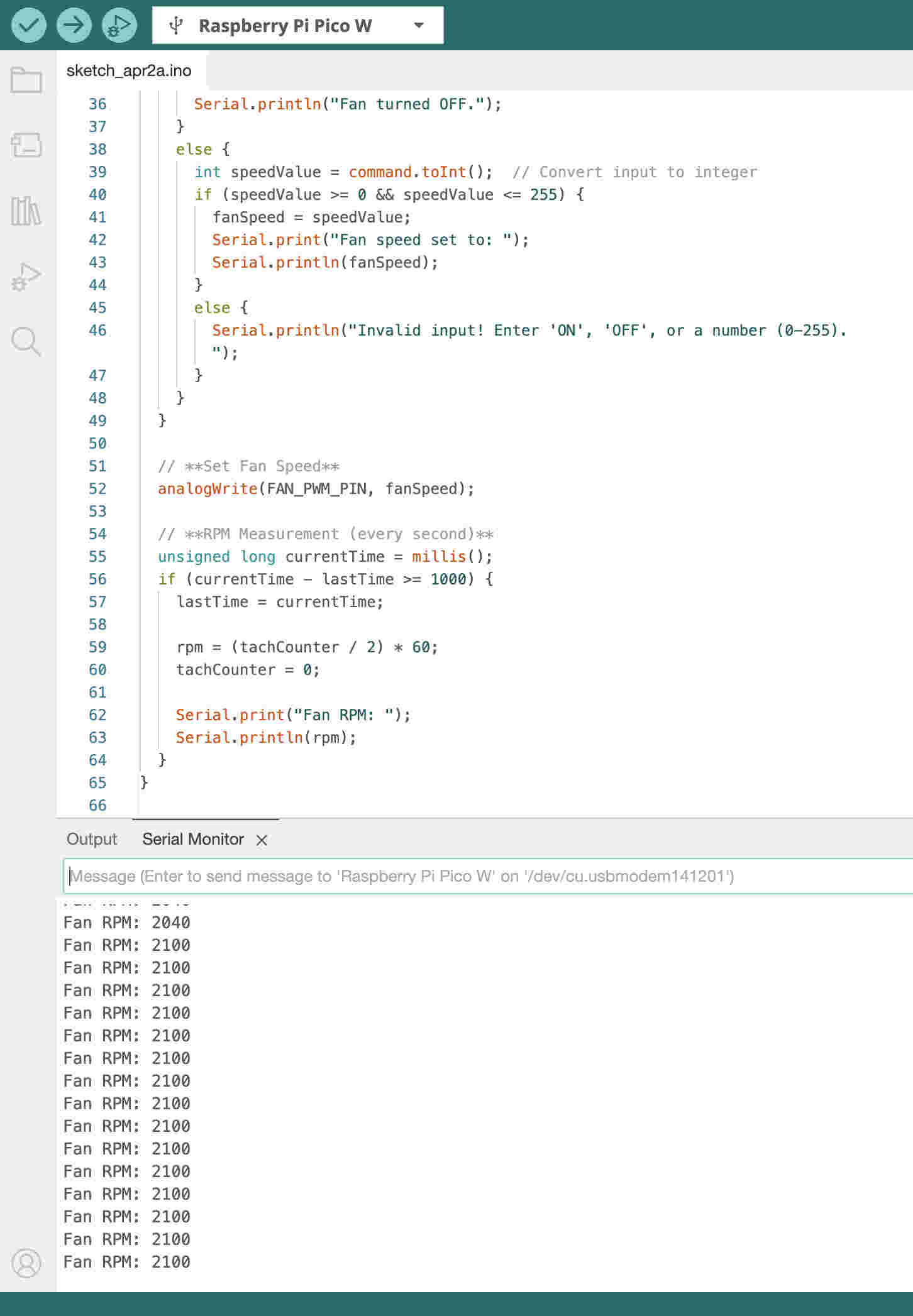
Here I have abn external power source providing 12.3volts at .22Amps, the fan here is running at peak rpm of 2100.

reflection
The video above also shows that the fan is moving a good amount of air. In fact it is moving so much air that the extra fan starts to to spin when placed in front of the strainer. Finally getting to do what I been waiting on since Fab-Academy has started. This has been the best week since starting this project. To finally see air moving through the testing section has motivated to know add start making the other parts and finally having the fun of presenting this project with my students form MINT. Link to the PCB made for this project