03-Computer-Controlled Cutting
This week we started our groups assignments where we got introduced to the Fab labs safety rules and how to use the
the laser cutter. We looked over how the how to clean an focus the laser finding the range where the laser cut the best.
We also looked at figuring out the kerf. The kerf is the the material that the laser beam burns away. It was really nice to
work with the others and learn how to set up the laser.
What we learned this week in our group assignment:
On our own
quick into duction to the laser cutter Fusion edge
The laser cutter we got to work with is the Fusion Edge from Epilog laser. This model has a selffocusing laser and a its own filter system with air asist. it also have a netwerk conection to a stationnary computer. No need for running back and forth with a USB to ajust settings.
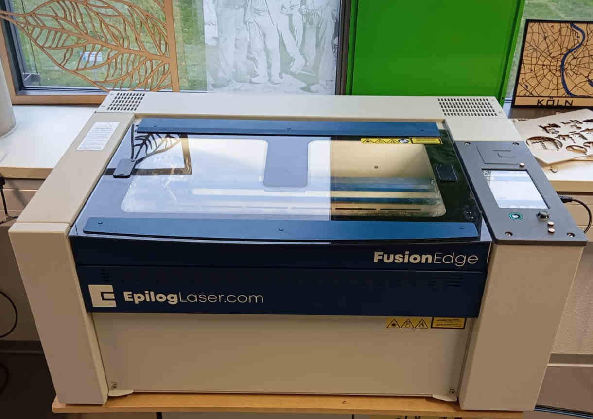
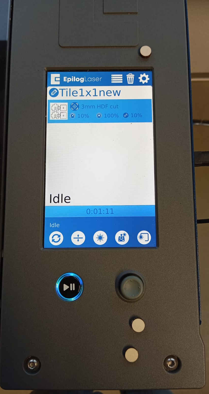
The laser has a built in touch display where you can also go back to job that you had done before.
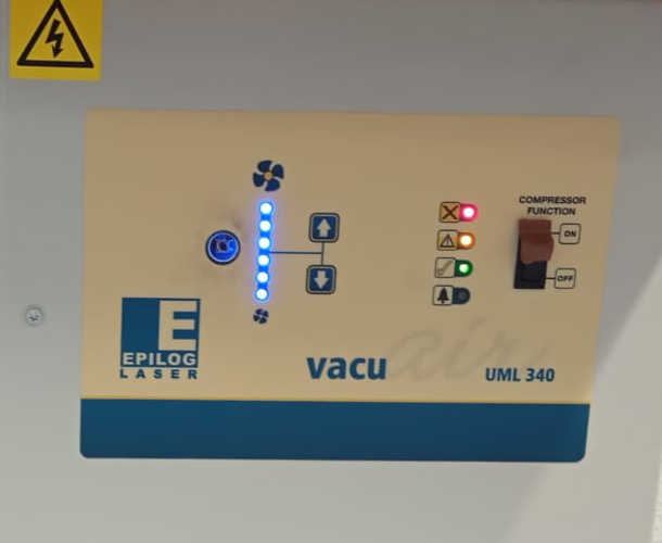
Under the laser there is the filter which needs to be turned on before a job is started.
vinylcutter
The vinylcutter is a great example if computered aided cutting (CAC) that combines digital design with precies cutter technique. This allows you as a designer to create intricate shapes, logos, and text that are then cut from materials like vinyl, paper, or fabric. This have found its way into many start ups that deal with signage, custom apparel, and arts and crafts.
In last week's assignment, I worked with Inkscape to create a custom vector that I can now import into Silhouette Studio. It is worth noting that you can also use Silhouette Studio to create your own designs without the use of Inkscape. If you own the full version of the software, you can also save files as DXF, which can then be used to make laser cutting templates and designs.
Using Silhouette studio
In Silhouette, you can create or import SVG or DXF vector files, which you can either
purchase or find for free from various sources. Another option in Silhouette is to create
your own vector/2D drawing using the tools in the side menus. This is quite intuitive, and
you can experiment without worrying about making mistakes. Since I created my own vector in
Inkscape last week, I am importing the logo now.
 If you have an image that you would like to import, simply go to File > Open. Once the image
is uploaded, you should see the following image.
If you have an image that you would like to import, simply go to File > Open. Once the image
is uploaded, you should see the following image.
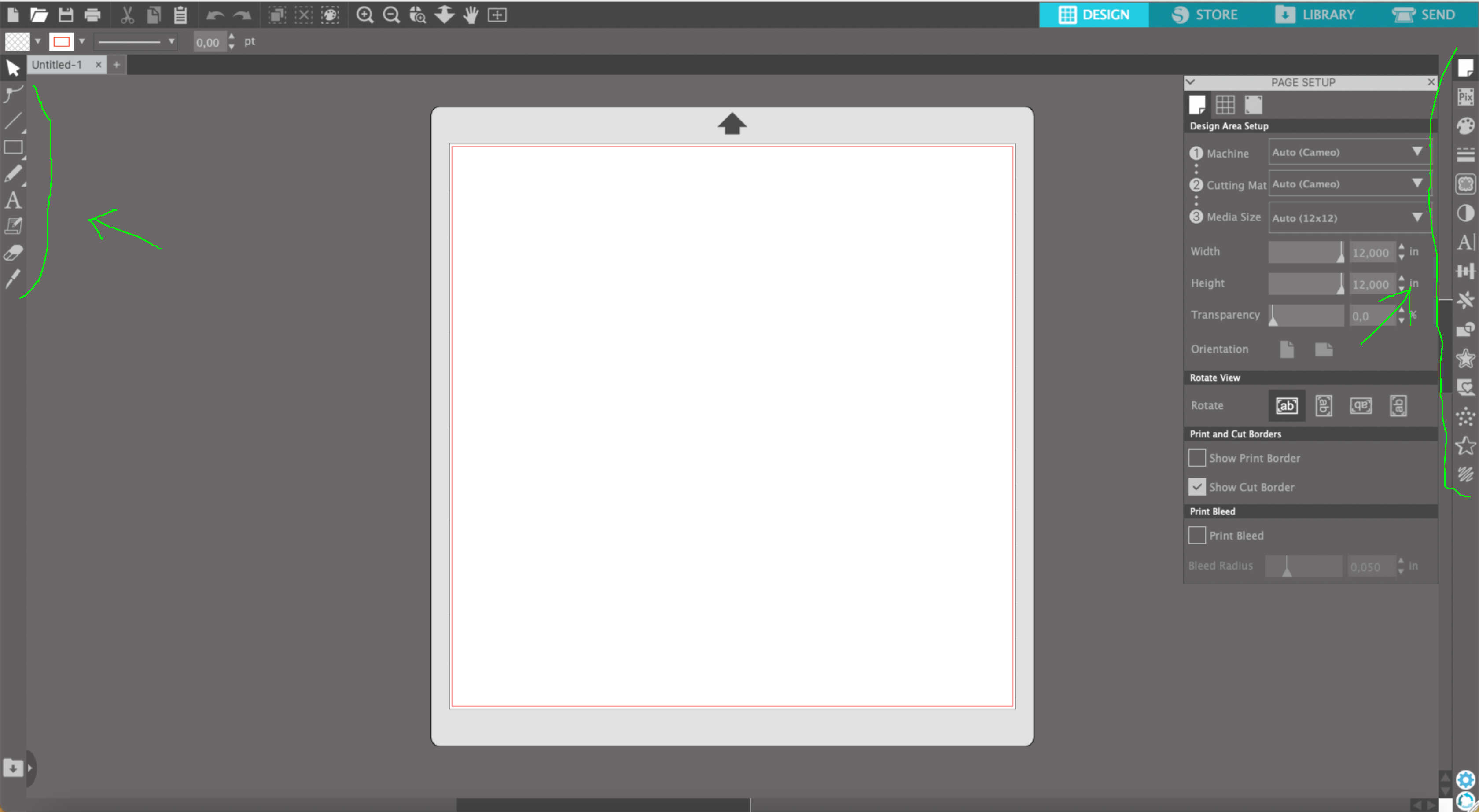
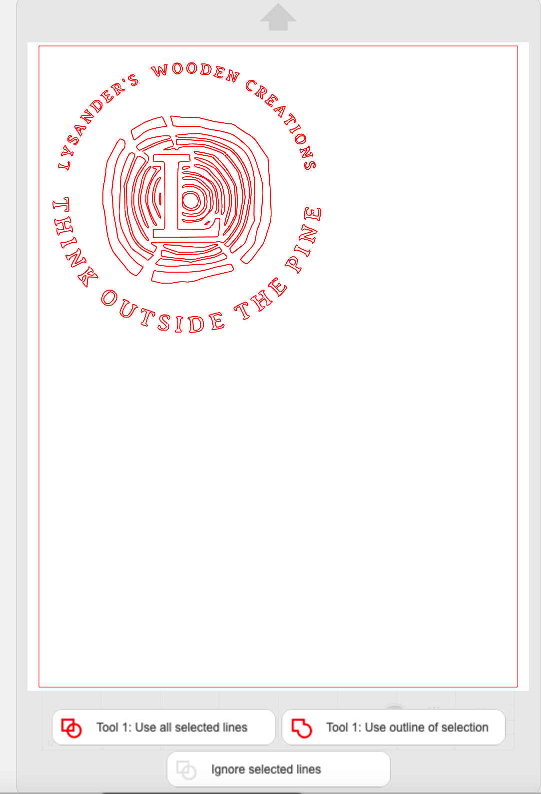
 Once the image is uploaded,
you can adjust its size to your liking. If, like me, you’re comfortable working in inches,
you can keep the original settings. If not, go to the Edit menu, select Preferences,
and then navigate to the General tab where you can change the units of measurement.
After uploading the image, you should see the following screen.
Once the image is uploaded,
you can adjust its size to your liking. If, like me, you’re comfortable working in inches,
you can keep the original settings. If not, go to the Edit menu, select Preferences,
and then navigate to the General tab where you can change the units of measurement.
After uploading the image, you should see the following screen.
Once you're happy with how you've
scaled your image, you can go ahead and set up the printer.
Getting stared
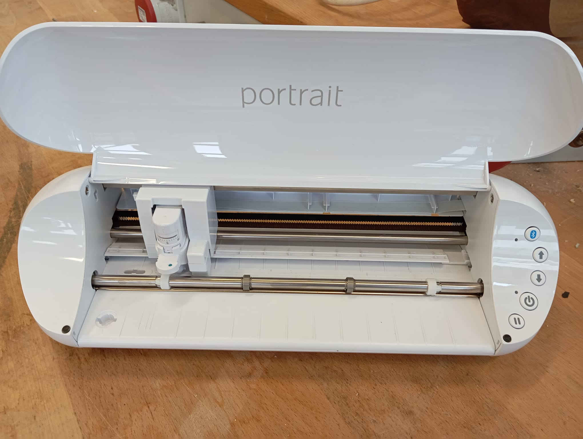
Now lets look at what comes with the plotter. 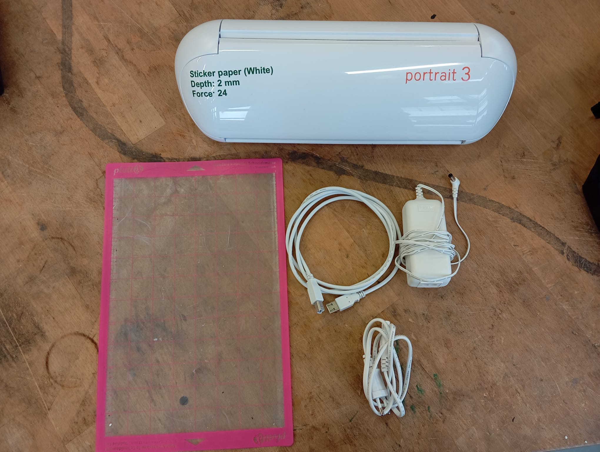 you should have:
When you open the printer, you will see five buttons: Bluetooth, the up arrow key, down arrow key, pause, and
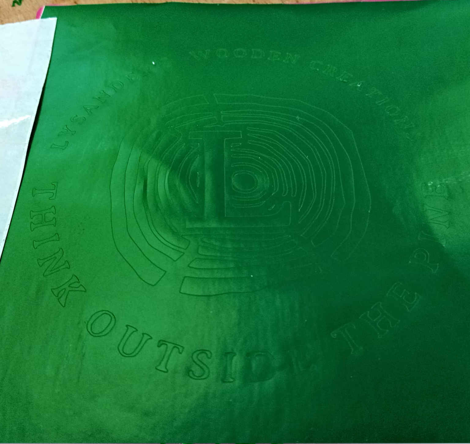
power button. Once you have applied the vinyl foil to the backing, you can insert it into the printer by pressing
the up arrow key. Make sure the sheet is inserted evenly, as this is important to avoid a misaligned cut.
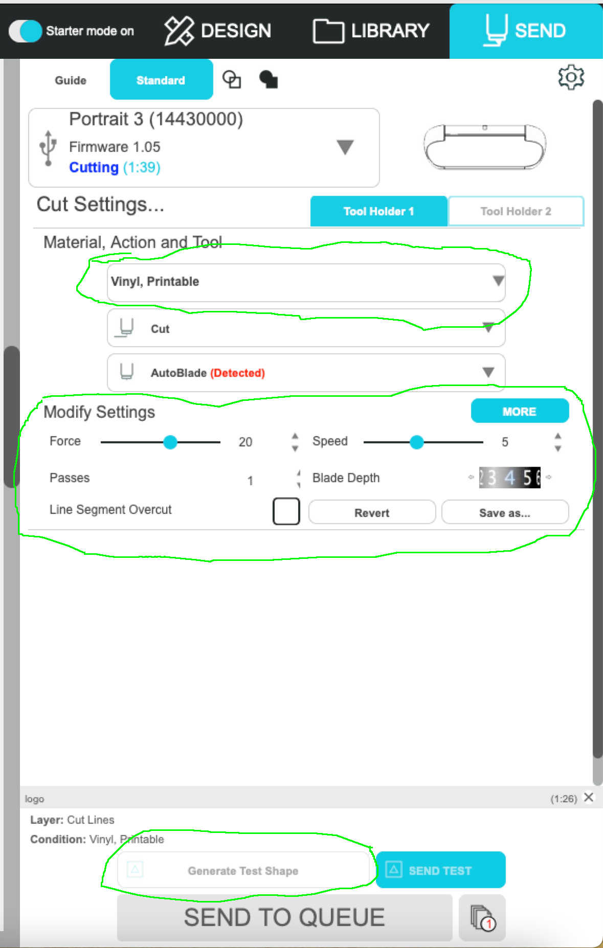
After setting up your plotter, you can connect via USB or Bluetooth. In my case, the connection worked automatically with the USB cable. It's important to note that you need to select which plotter you're using, as there are different versions, each with a pre-programmed name in the hardware. In my case, it was the Portrait 3.
At the top right-hand side of the screen, there’s a button that says 'SEND.' Click this button, and you’ll be guided through a menu to get started. I followed the instructions until I reached the next menu, where I could adjust the settings of the plotter for the vinyl I was using.
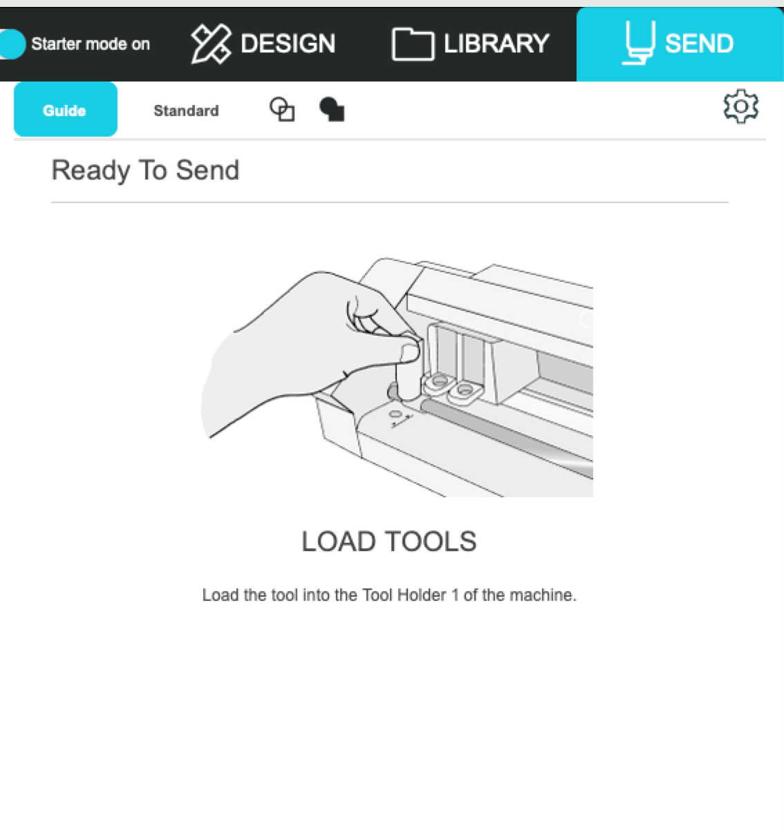
At the end of the guide menu, you'll reach the manual menu, where you can adjust the settings based on the type of material you're cutting. The presets are already configured, and in my experience, they’re sometimes good. However, I recommend always doing a test cut with the material you're using. There's a button at the bottom of the screen that lets you run a 'Generate Test Shape.' If the test cut is too soft, too slow, or not quite right, you can adjust the settings as needed. You can choose a different material from the list depending on what you're using, and modify the cut force, speed, and number of passes. For me, the preset settings worked just fine.
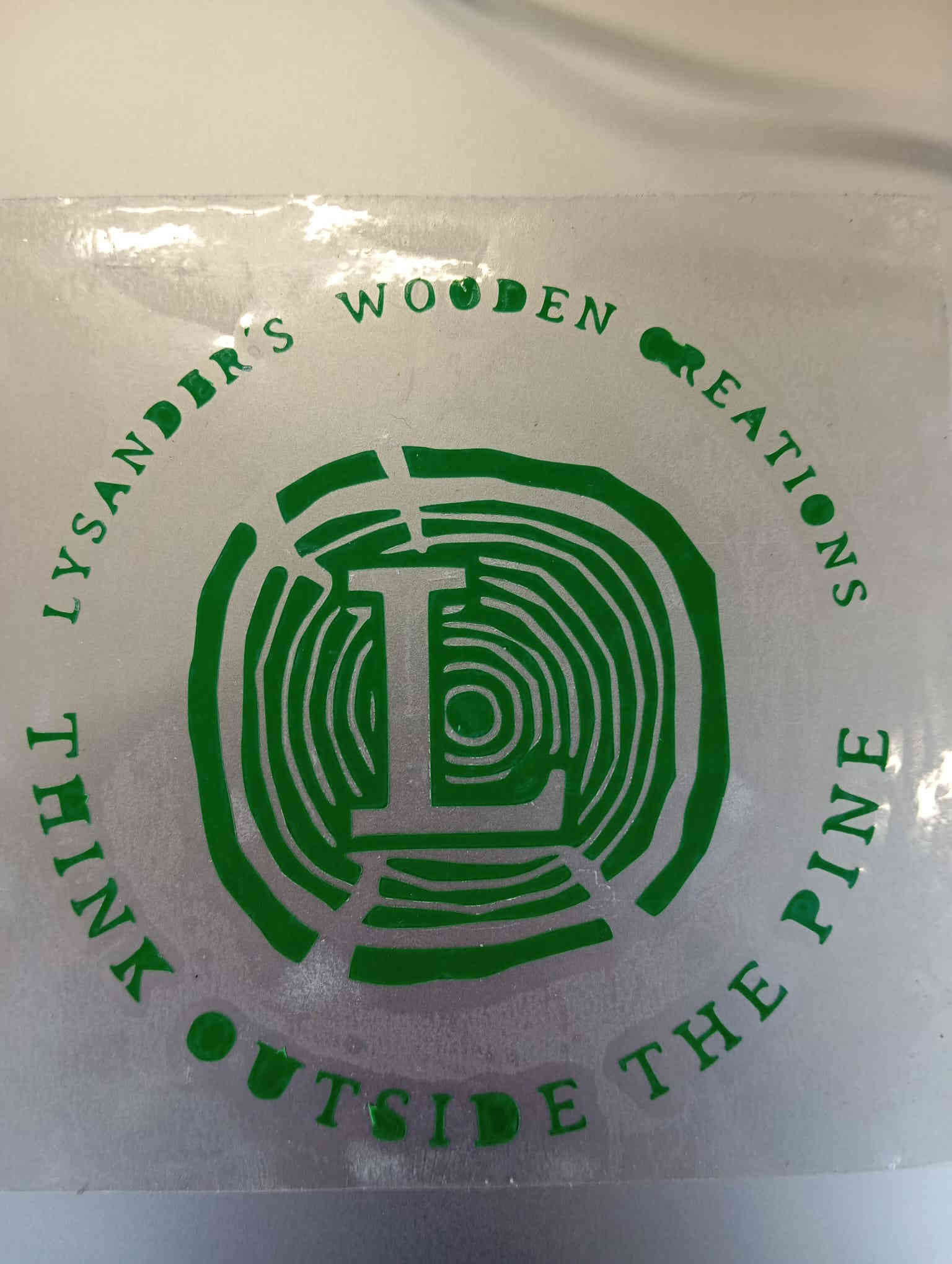
Since I didn't have a place to stick the sticker, I left it as is and used some clear vinyl to attach it to my laptop for safekeeping. You may have noticed that some of the letters are incomplete—those required a needle to finish. This was just a test run to see if it would work, as I plan to cut a larger version of the logo to apply to a hoodie or T-shirt.
Parametric design
What is a parametric design? Parametric design is a computational approach where design elements
are driven by a set of parameters. Instead of manually creating each design detail, the designer
defines parameters (such as size, shape, or angle) that automatically adjust based on changes made
to those parameters.
How can I make the rule more clear? In my documentation booklet, I did several sketches, gathering
ideas until I came up with a final concept. I then predefined the parameters that suited the design.
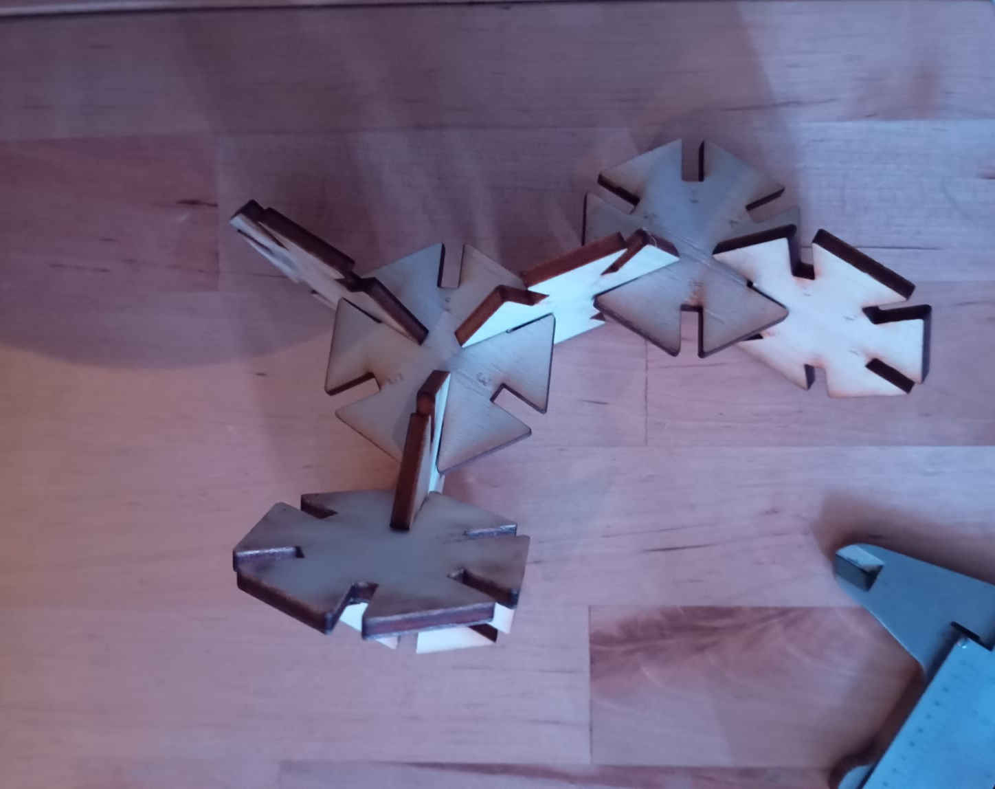
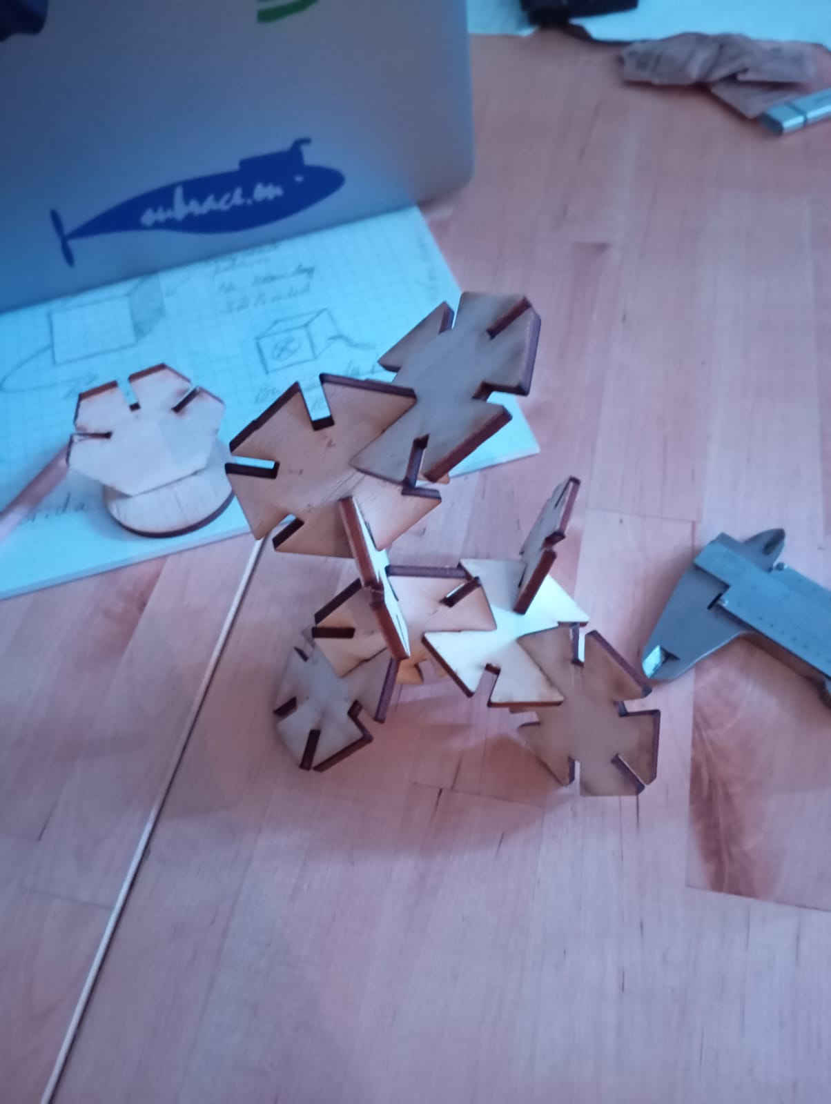
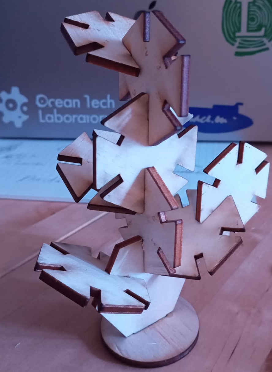
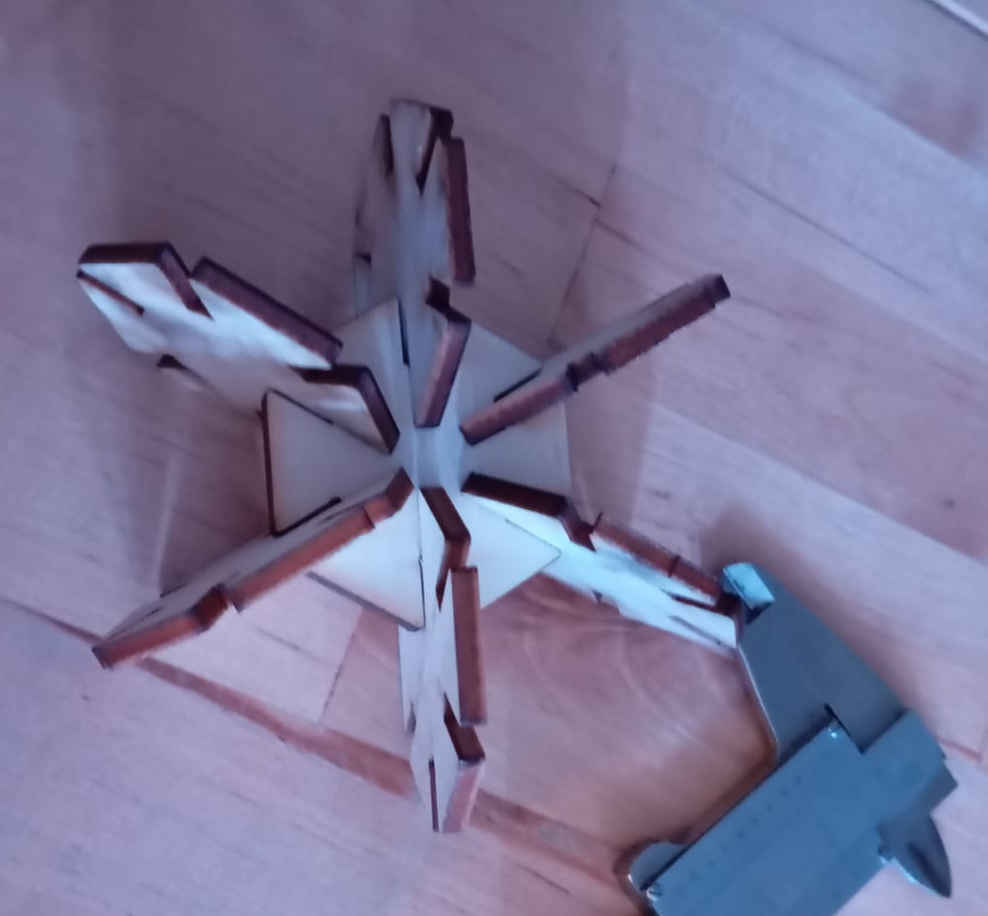
I decided to create a new game, aiming for something simple that anyone could enjoy. The game features
a hexagon-shaped tree with numbers 1 through 6
The games rules
Game Rules:parameters
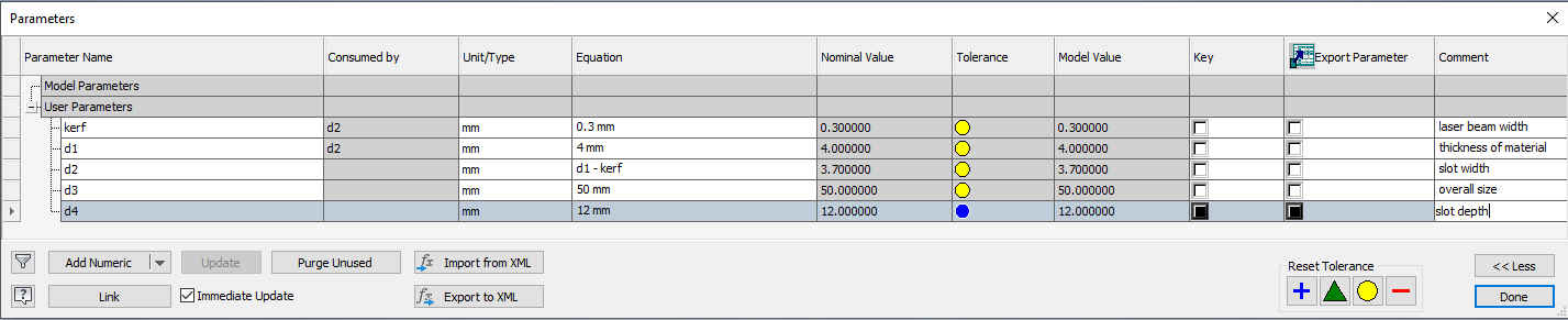
In order to create a parametric drawing, it’s important to set the parameters on paper first. This will save time when adding the parameters to the table of contents in the function. I showed last week where this function can be found. In the parameter table, I added the kerf and material thickness, among other parameters. I made sure to preset the kerf and material thickness so that any changes to the kerf or the material thinknes will automatically update all the measurements where it plays a role.
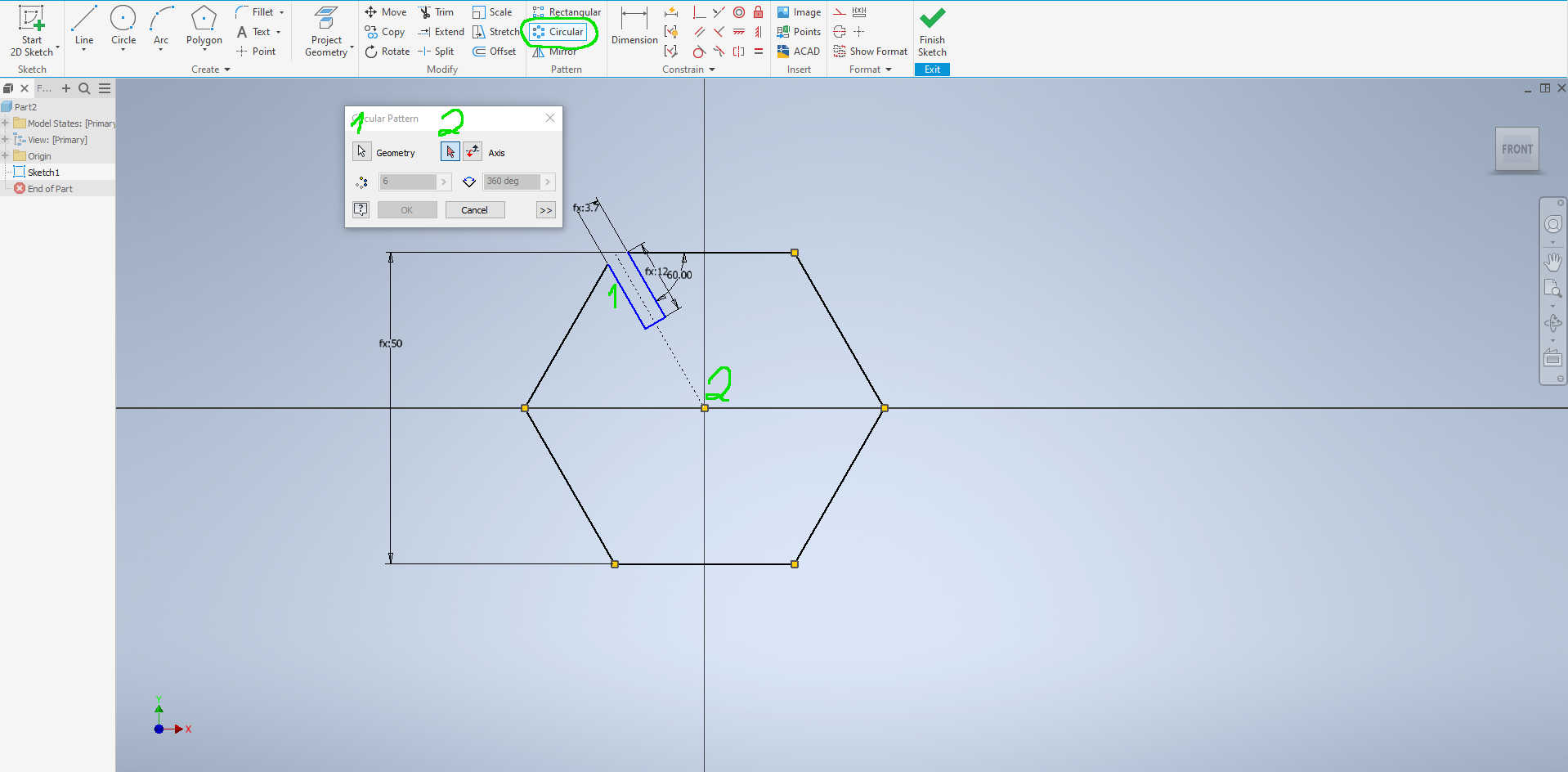
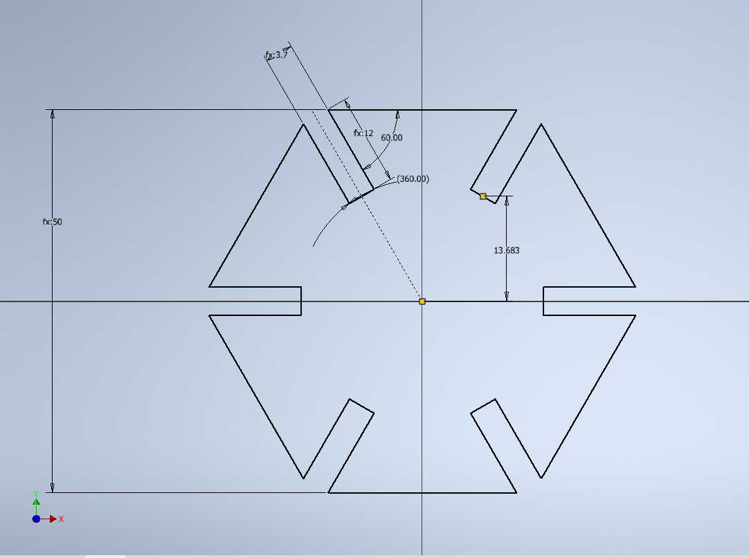
Once I had the parameters add I went and started a sketch on the XY plan. I than went and added the parameters to the drawing. Here is a image of the completed drawing. Next select the componts on the drawing that you want to copy. Follow the steps in the drawing to copy the pattern in a ciricle. Select the midpoint as your axis.
Once the 2D drawing is complete, go to extrude and give in the parameter for the material thinkness.
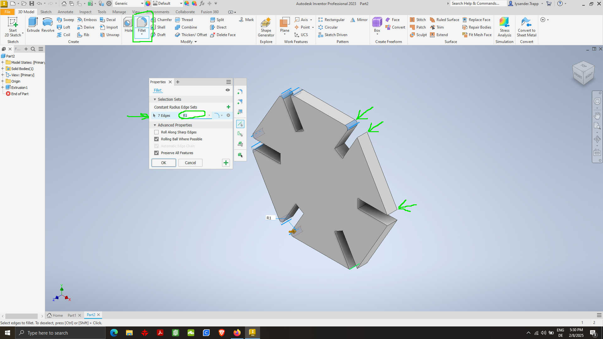
Next add a parameter to round over the edges. Then select the round over function.
After redering and adding a couple of touches, like embeddig some writting on the parts and the die. We end up with the following images:
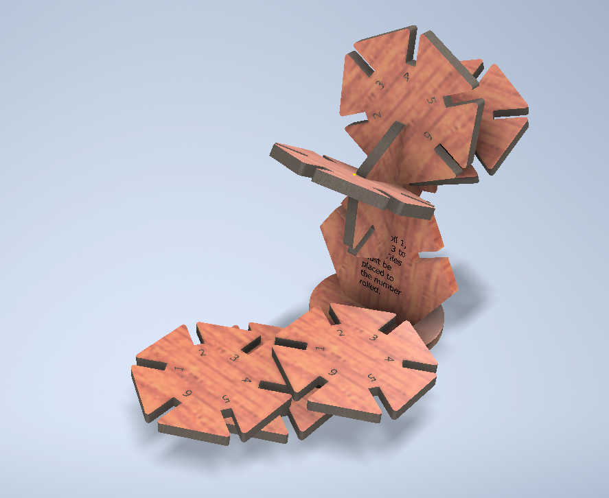
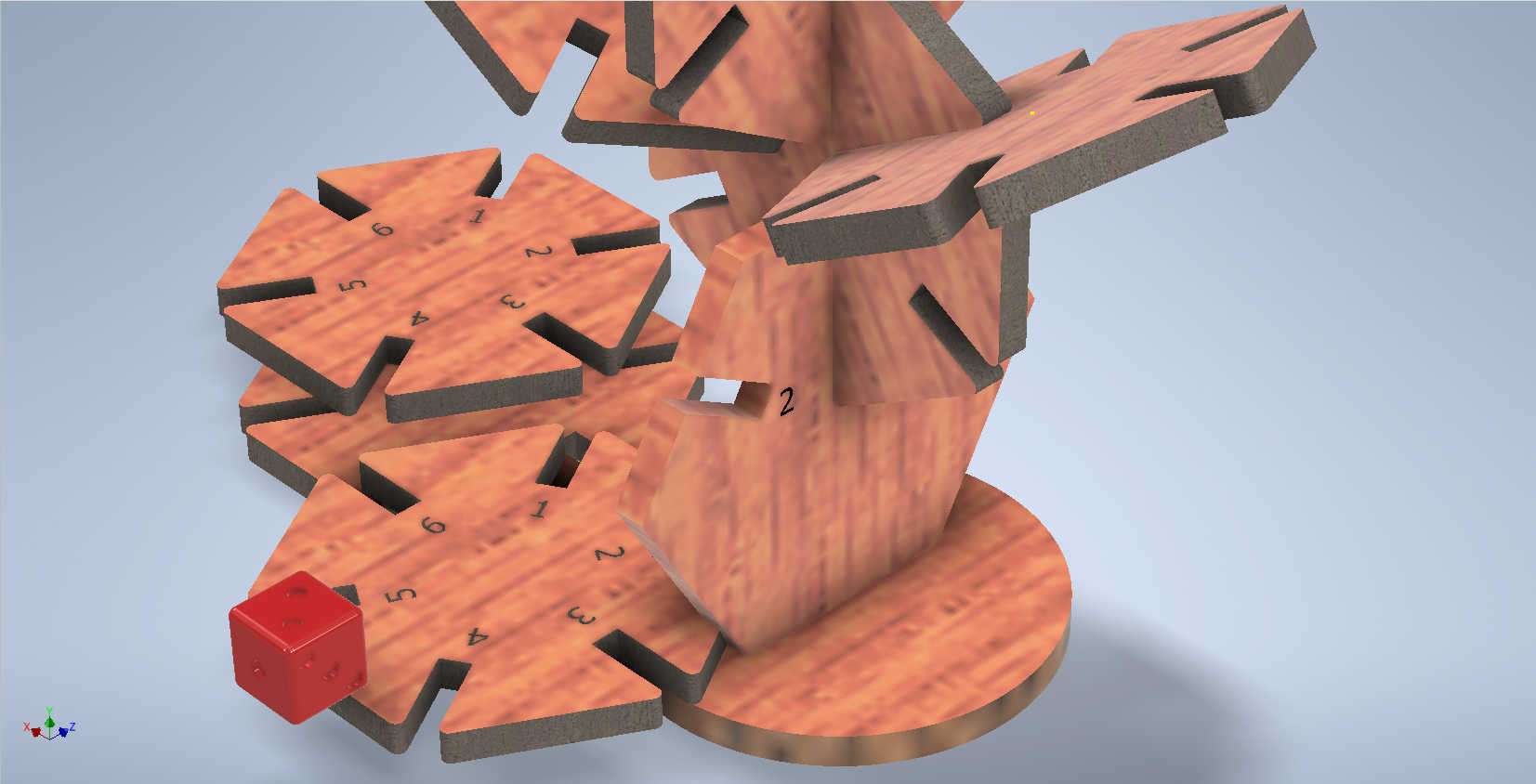
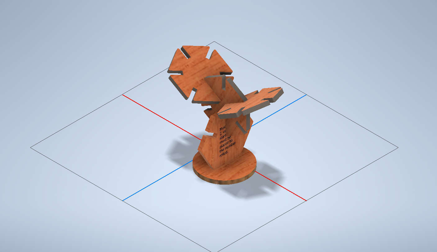
Hero Shots
 v
v
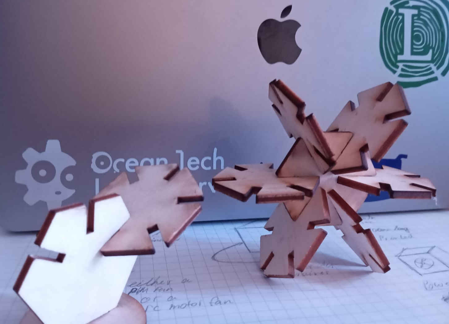
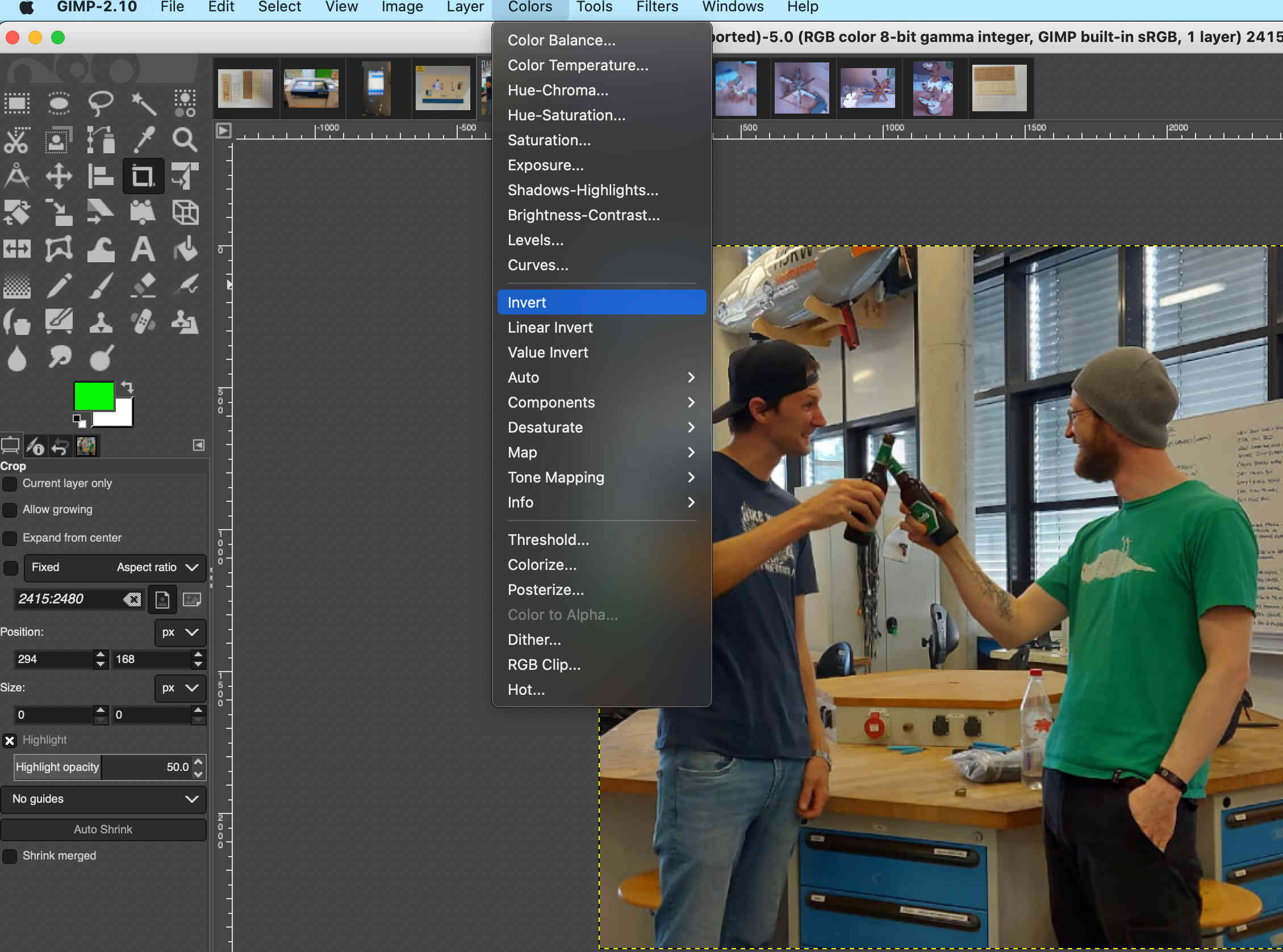
I decided to have a little fun today and asked Mika
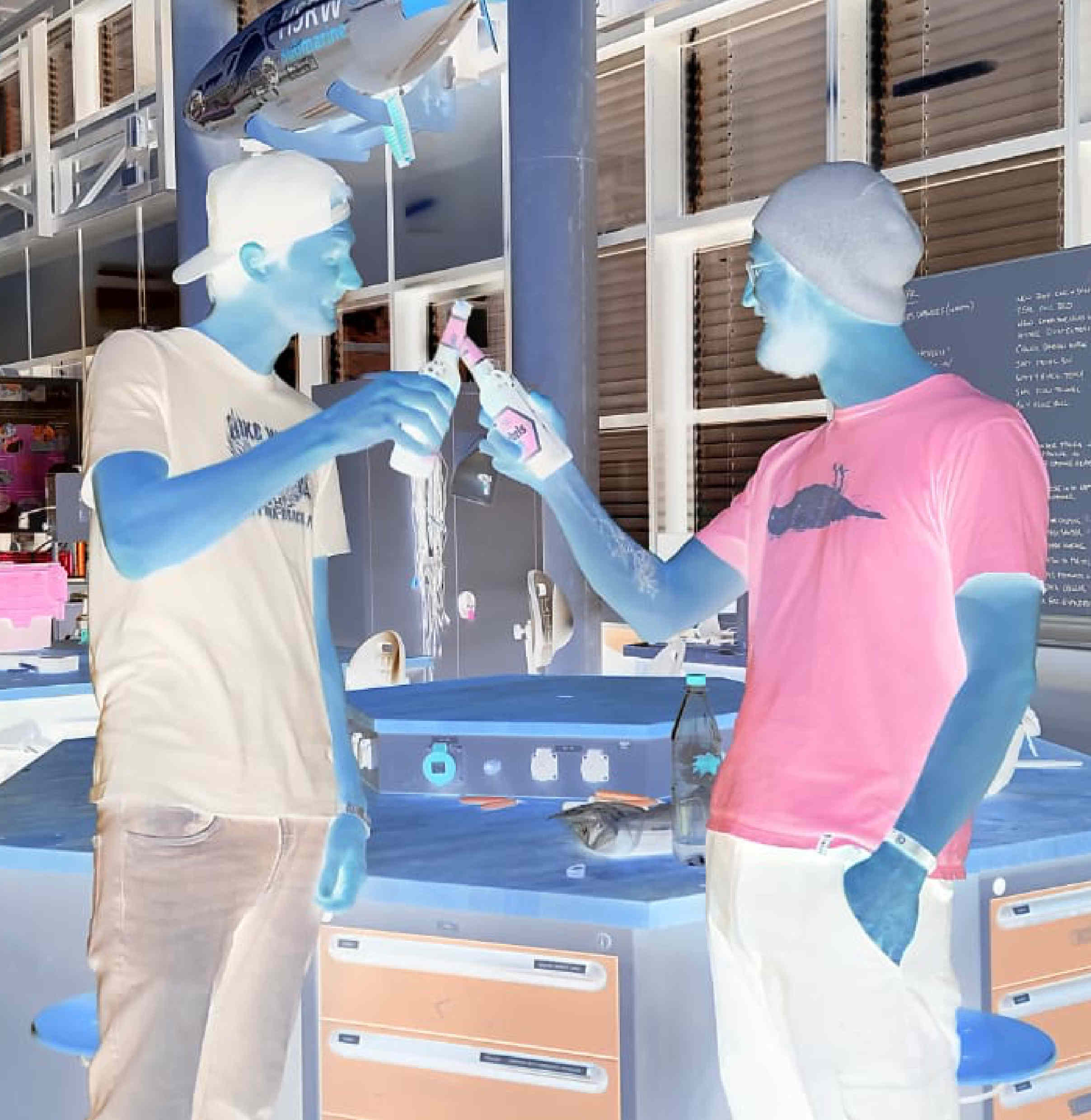
to help me with engraving an image. As for engraving, you need to invert the image.
I used GIMP to invert the image. You can also do this with Inkscape, but it is not my favorite tool.
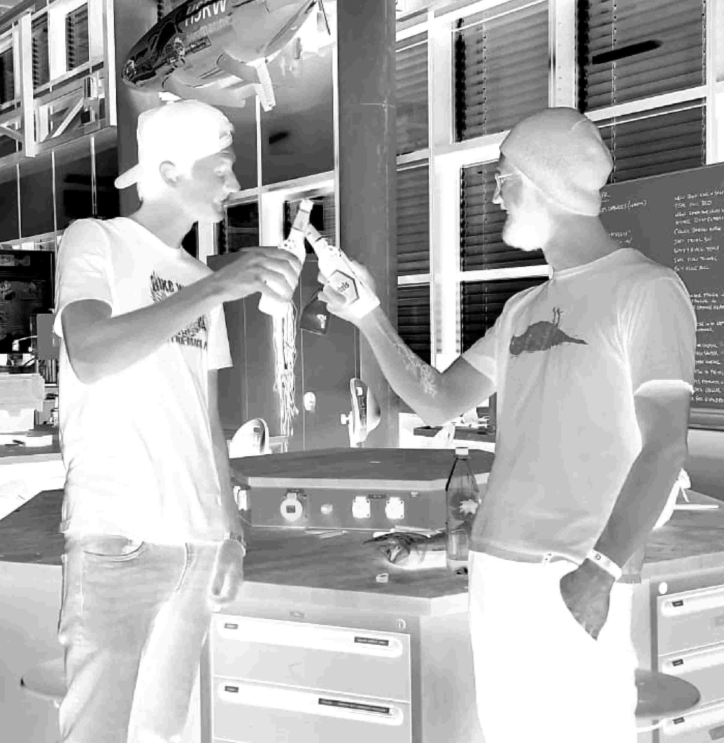
After you have intverted the colors you can play with the contrast. Change image to black and white by selecting Image> Mode > Gray scale turning the
image to blak and white. Next funtion can be found under Color > Brightness - Contrast which needs to be adjusted to highlight bits and parts of the image.
I played with the setting and with the hlep of Mikas know-how we found the right settings pretty fast. We than uploaded to the image to the software
for the laser to and ajusted engraving settings to the material at hand gave it a test couple of test runs. each time adjusting the contrast
and speed and Resolution also called DPI here are the final setting: DPI 600, speed 100%, Power 60%.
Links
© 2025 Lysander Trapp. This work is licensed under a Creative Commons Attribution-NonCommercial-ShareAlike 4.0 International License.
Made for Fab Academy.