05 Assignment 3D scaning and printing
3D Printing
What is it that a 3D printer really does? The easy answer is that a 3D printer uses computer aided-design to creat a three diamentional object through additive layering method. This involves laying layers of materials on top of each other. Materials such as platics, composites, even bio materials. This process give the printer the ablitiy to produce very complex shapes and geometric structures that would otherwise not be feasible to create with a subtractive methods such as CNC. This includes creationg hollow parts that could have internal structures like trusses that are than used to give a part strength but at the same time reduce the over all weight of the part. The Part is also able to keep the same material inside and outside. With 3d printer that can print wuth different materials at the same time, it now is also possialbe to have one material on the outside and another on the inside. This comes to a great advantage with more than one material is needed to creat the desired strength of a structure well. The material that are used very greatly and also come in different colors. There are many different types of filaments, the most commonly used one is Polylastic acid, commonly known as PLA. The reason that PLA is being used as much is its characteristics, havingthe ablity to be biodegradable and being able to melt at a low temperture.
Most commenly used filaments
Each of these materials comes with different properties, which can be used for different purpesses depening on the what is being prototyped. It is important to know some of them as this can impact the project, such as strength, durabillity, flexablity, aesthetic appeal, environmental factors, ease of printing, cost, food safe, medical, chemical resistance, recyclabltiy, etc. These all should be taken into consideration. More information on this topic can be found in our group assignment.
What a 3d printer can do but not a CNC
One of the challenges this week was to create a part or object that a CNC cannot do, but a 3D printer can. This was a nice challenge
for several reasons. Coming from the work of a machinist, there are a lot of things that a standard CNC can make, and even more that
a 5-axis CNC can do. There were loads of ideas running around, as a 3D printer can create inner structures that a CNC could never produce.
3D printing a cube with a structure that no one could see felt like a cheat. Being an instructor for bionic and digital manufacturing helped
form this inspiration—topology came to mind.
What is topology? Topology describes how elements are bound to each other. A really good example of such structures can be found in bird bones,
which provide strength while also being lightweight, allowing the bird to fly. Simply put, birds have lots of triangular structures inside their bones.
Topology can be used to find stress points as well as to reduce the weight of a part by analyzing the triangles in the algorithm in Fusion.
Armed with this information, I opened Fusion 360 and started a sketch with the following dimensions: 50mm width and 75mm height. Next, I rotated the 2D
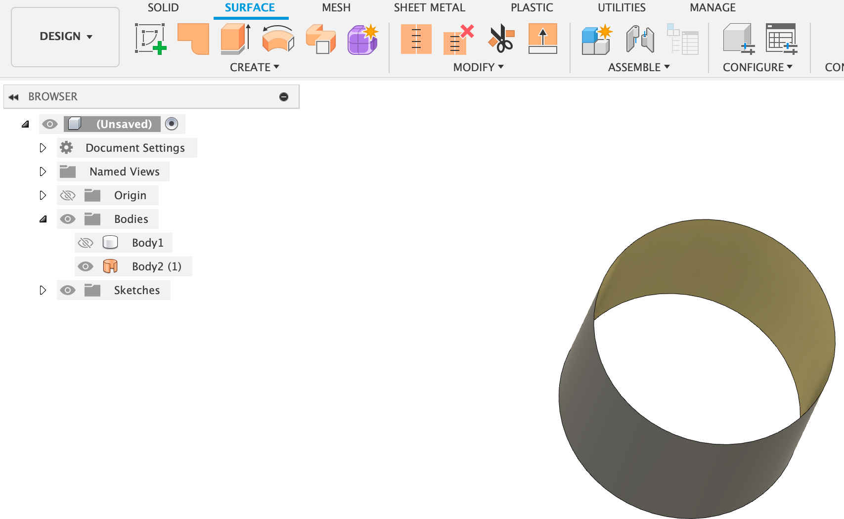
drawing to create a cylinder. Then, go to Surface > Create > Offset. Select the outer surface and leave the offset at 0.0mm.
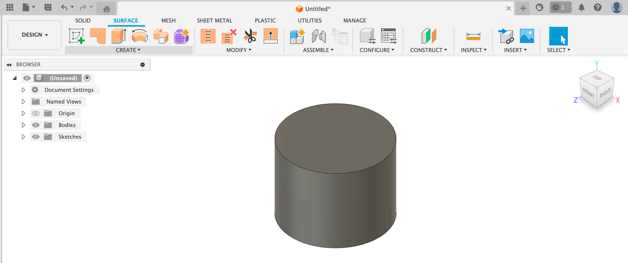
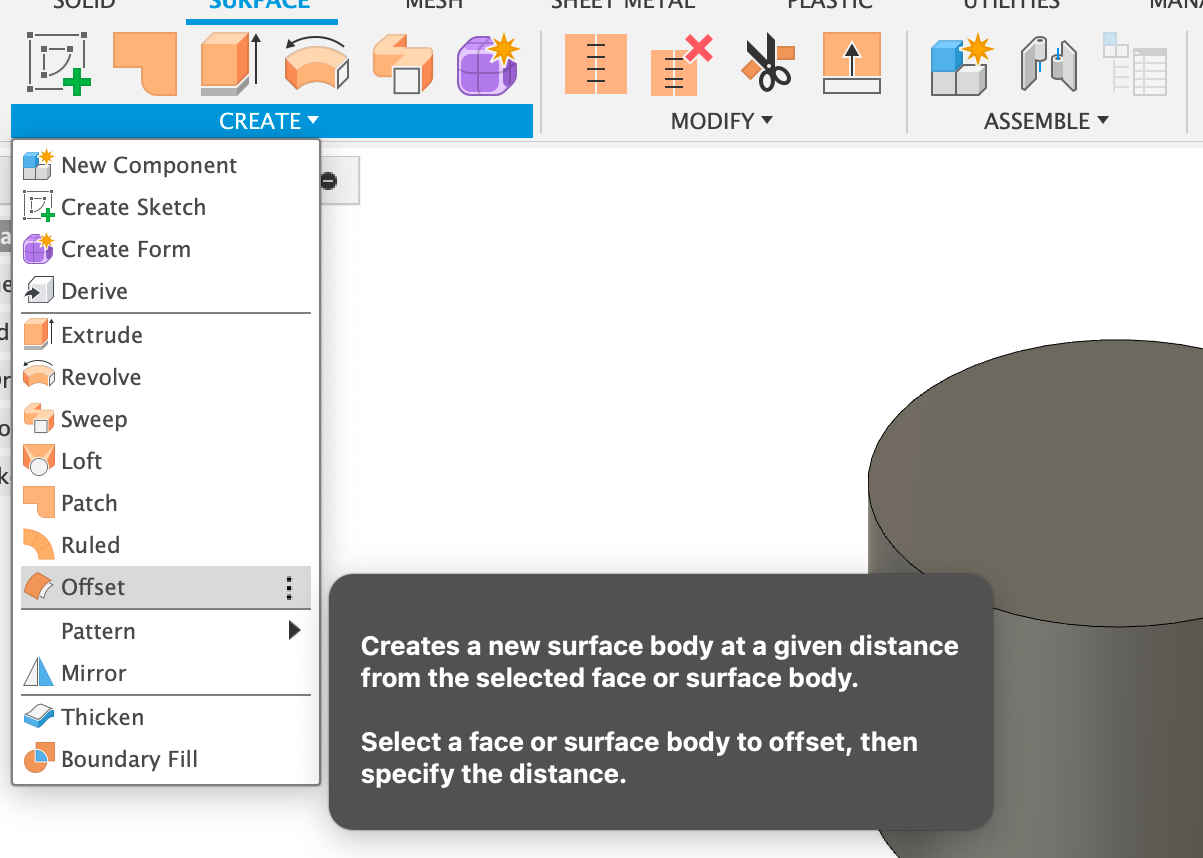
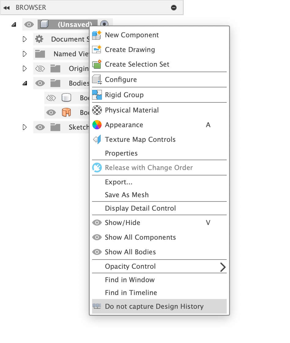
This will leave a sleeve of the cylinder. This is where the topology will be applied. An important step here is to turn off design history,
which can be done by right-clicking on the part's name. In this case, it was not saved, but it should be at the bottom of the menu.
The next step is to go to Mesh > Create > Tessellate. In the menu, select Preview. Now, play with the Aspect Ratio in that menu. By adjusting
the Aspect Ratio, the number of triangles will either increase or decrease. The more triangles, the longer the rendering process will take.
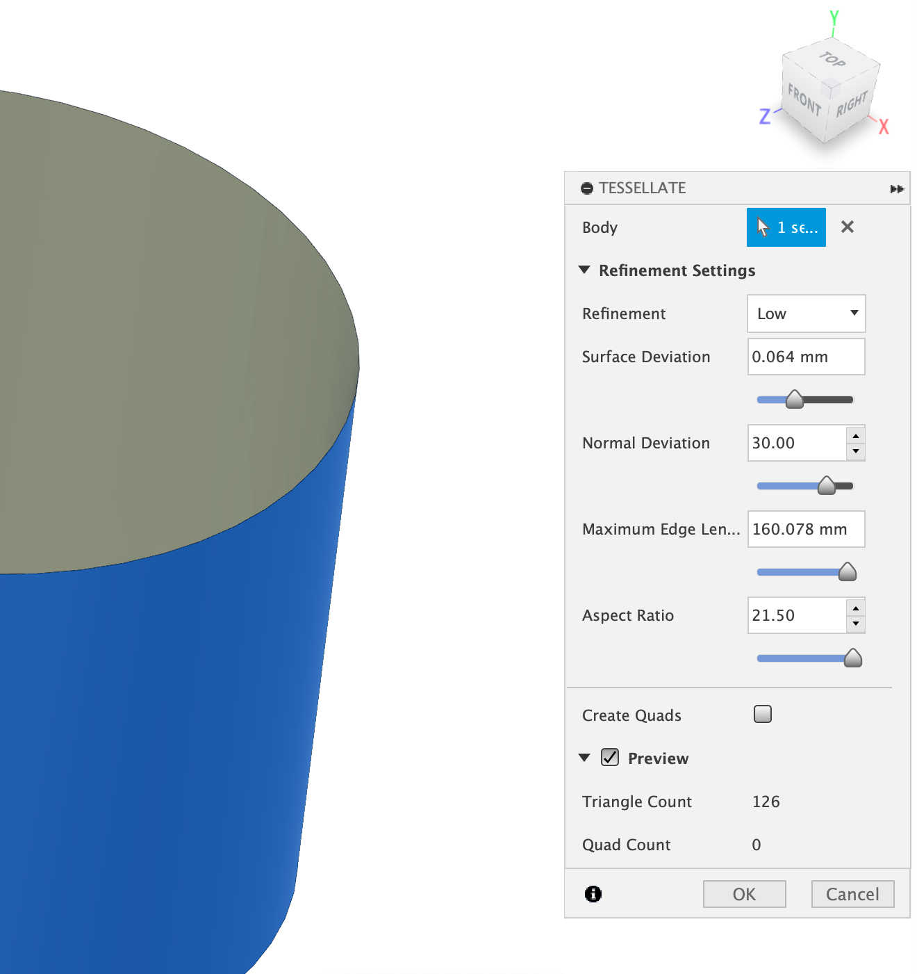
This will outline the a number of triagles on the cylinder. Now that the triangels have been marked out, the next step is to use the Mesh function.
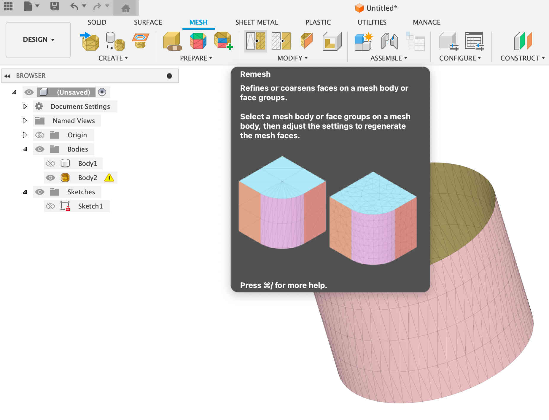
For this go to the menu Mesh > Remesh and select the whole body > uniform > preview. This will deform the cylinder giving it a new shape where
the trigangle depict the cylinder form.
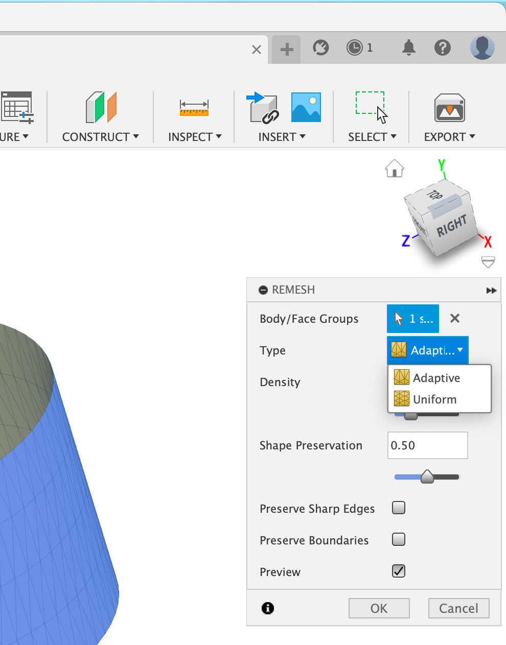
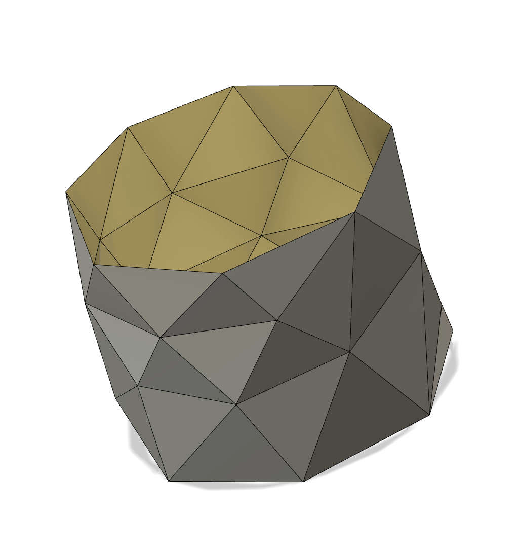
Now, this form has to be turned back into a solid body. To do this, select Modify > Convert Mesh. There are three options: Faceted, Prismatic, and Organic.
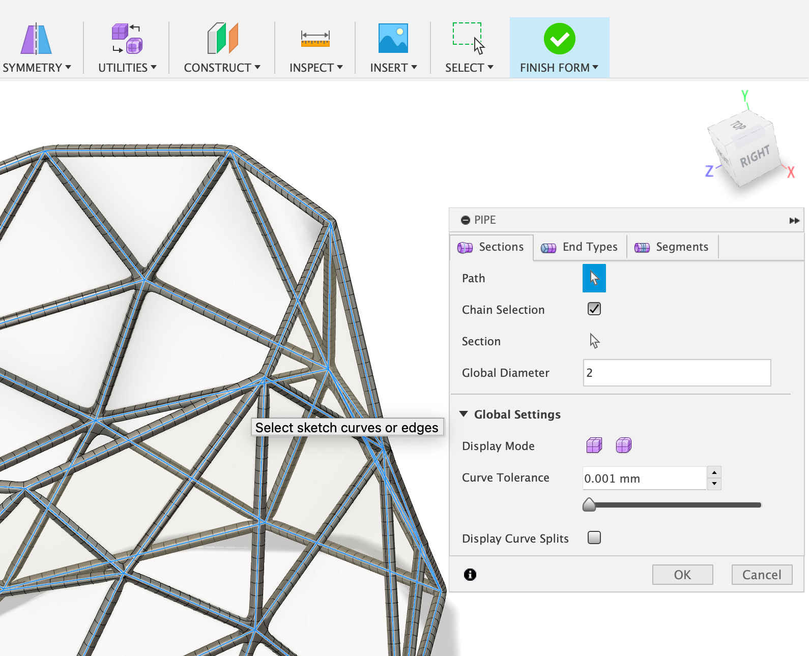
Select Faceted. After the mesh has been converted back to a solid body, go to Form Tools > Pipe. In the pop-up menu, make sure that Edge Priority is selected
under Select. In the Pipe menu, change the diameter to 2mm.
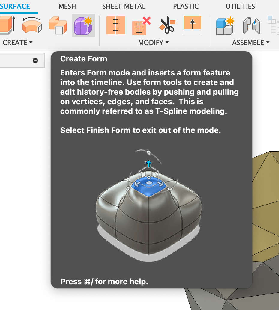
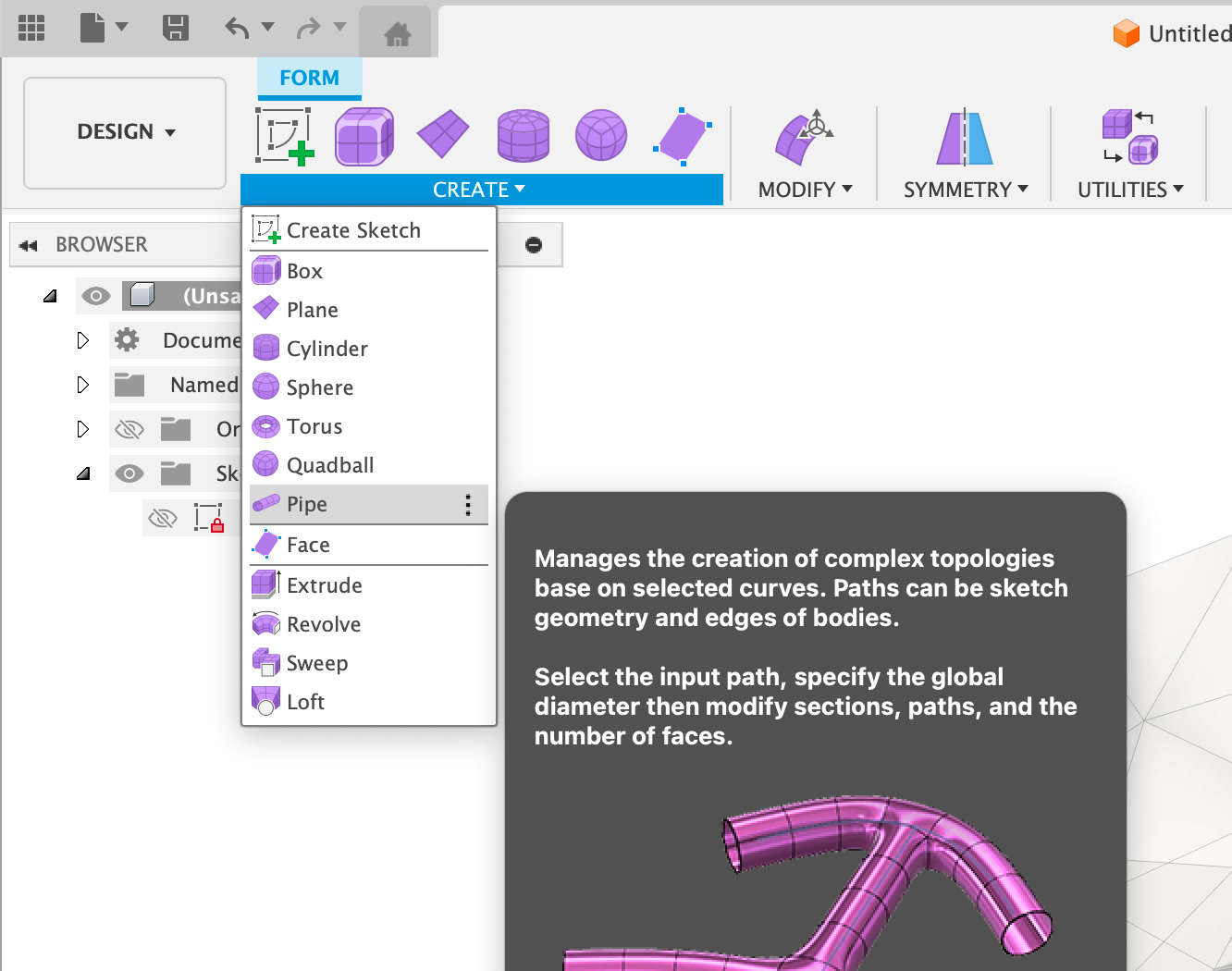
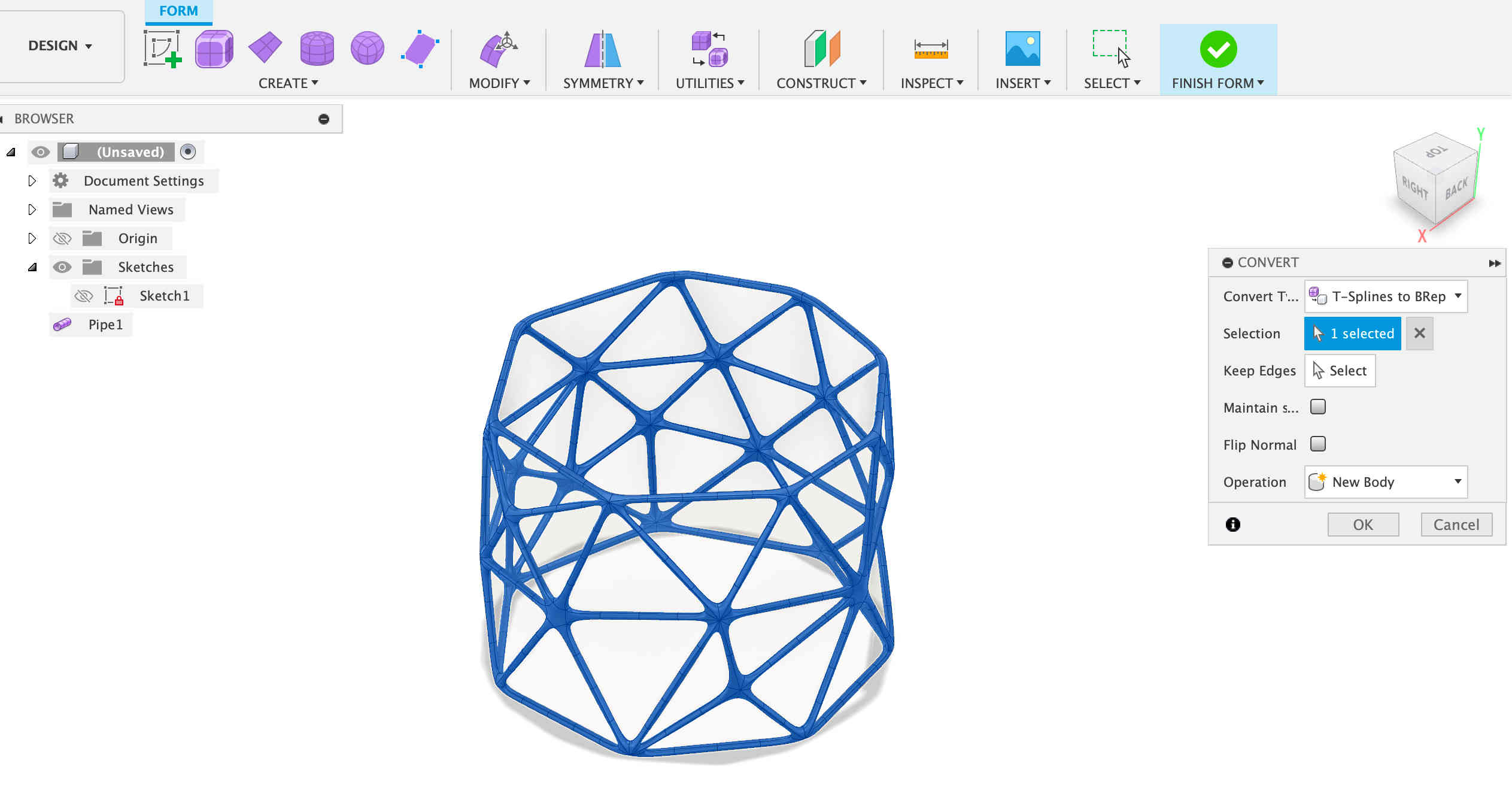
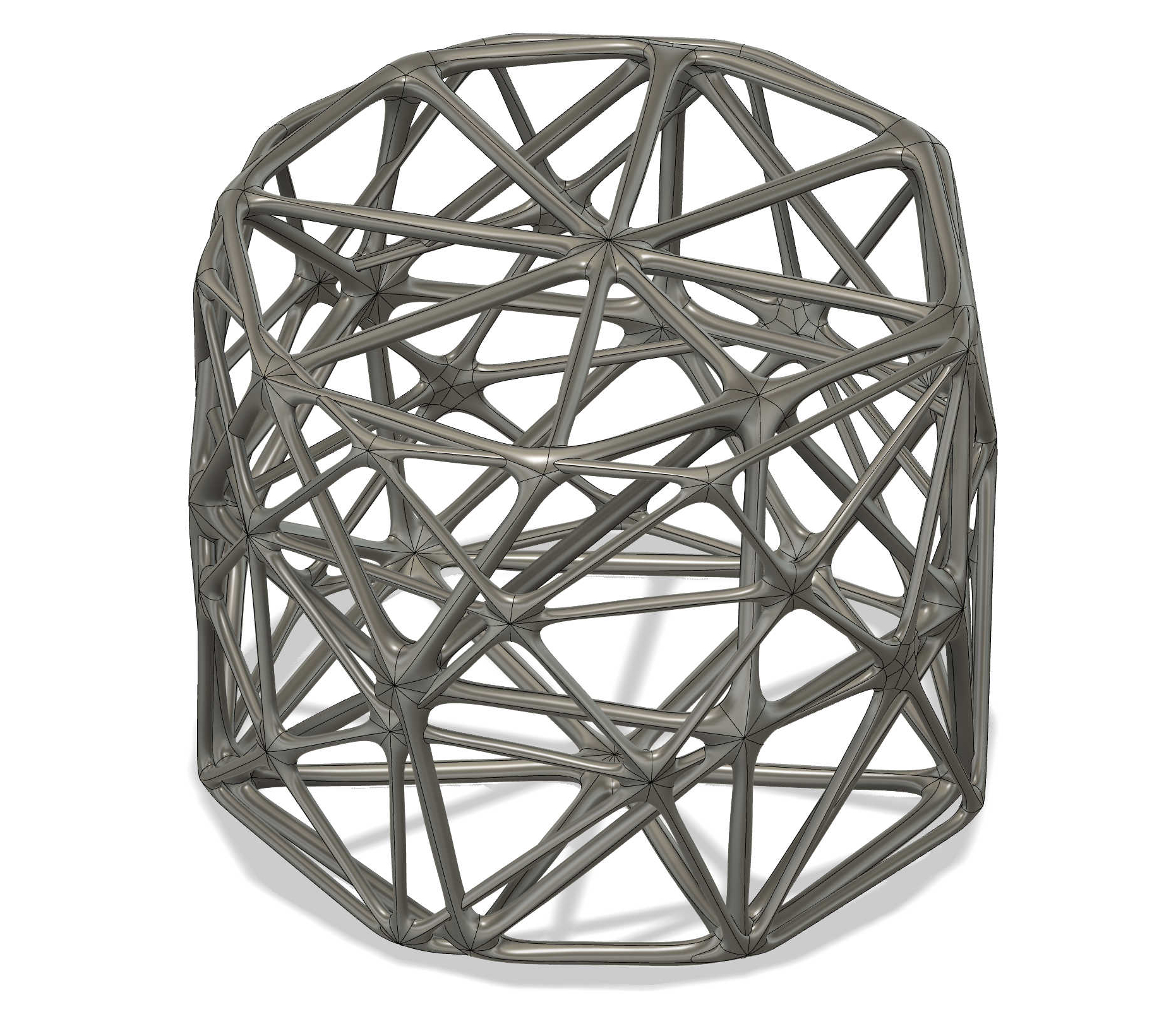
The last step is to go to Utilities > Convert. Once it has finished rendering, the structure should look something like this. Naturally, you can repeat these
steps multiple times to make the structure more complex.
This print was a challenge in itself, given the dimensions I had picked. It really challenged the 3D printer. The first challenge that appeared was
deciding which type of support to use—standard support or tree support. Knowing how these two different types of supports work was important.
Standard support encased the print, making it hard to even see what was being printed. Another challenge with this type of support was that it
is not easy to remove, increasing the risk of damaging the part during removal. This led me to choose tree support instead.
Tree support is generated by an algorithm that creates an organic structure resembling a tree. One major advantage of this type of support is that
it uses less filament. After comparing both options, I decided to go with the organic, tree-like support.
There is also the all-important question: which slicer should I use? There are many different slicers available, all offering the same basic
functions. Cura, PrusaSlicer,
Bambu Studio, and Creality Print each have
their pros and cons. The same can be said about different types of 3D printers. To me, the more important factor is which printer I use and the settings
saved in the slicer. This is something that everyone has to research and decide for themselves based on personal preference.
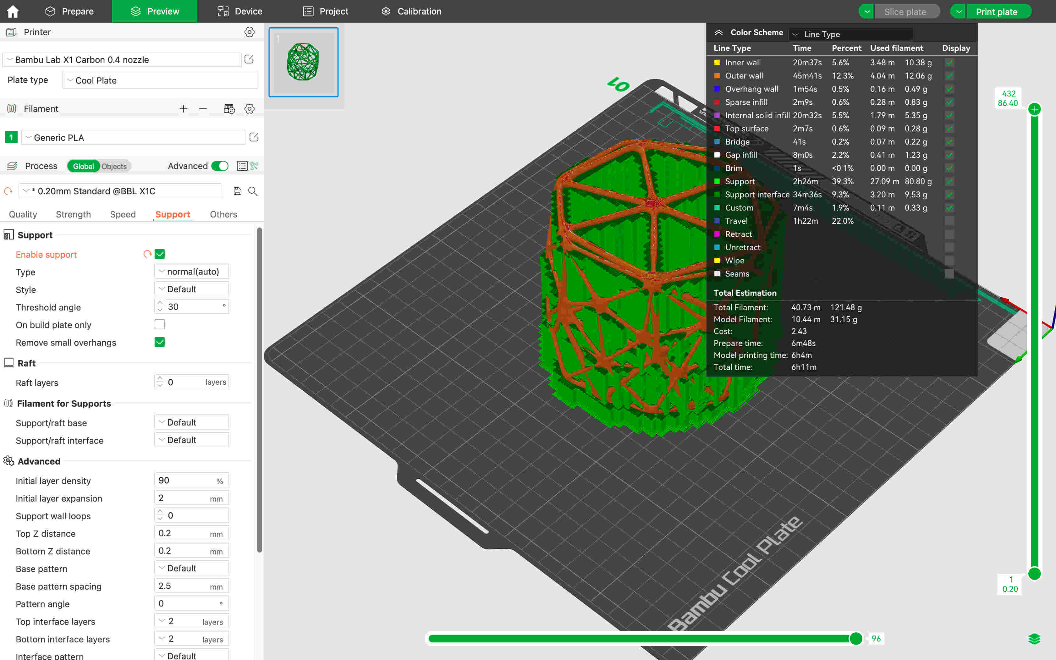
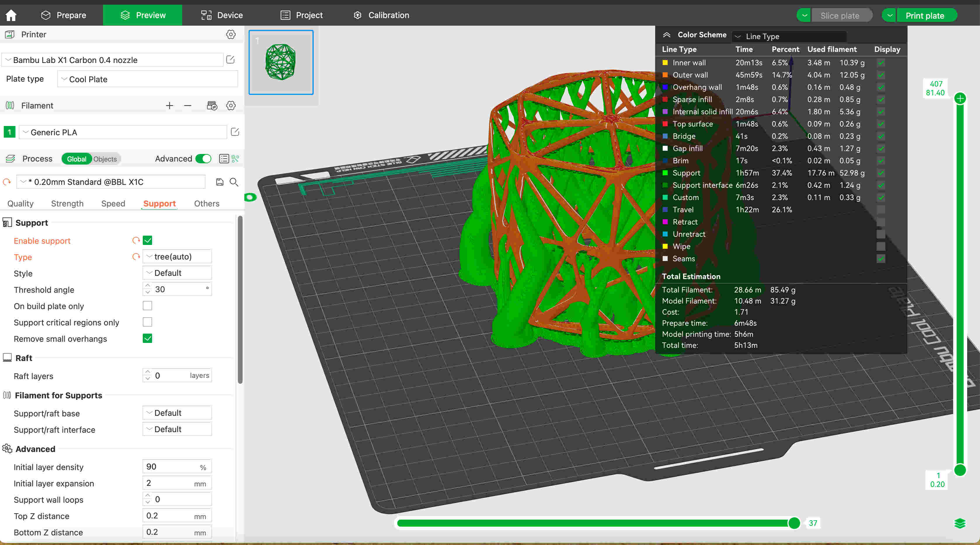
The two images above show the two differeces between Standard Support and Organic/Tree Support.This really does depend on what the model
looks like and personal preference. The next images are of the model being Printed, as well of the finished print.
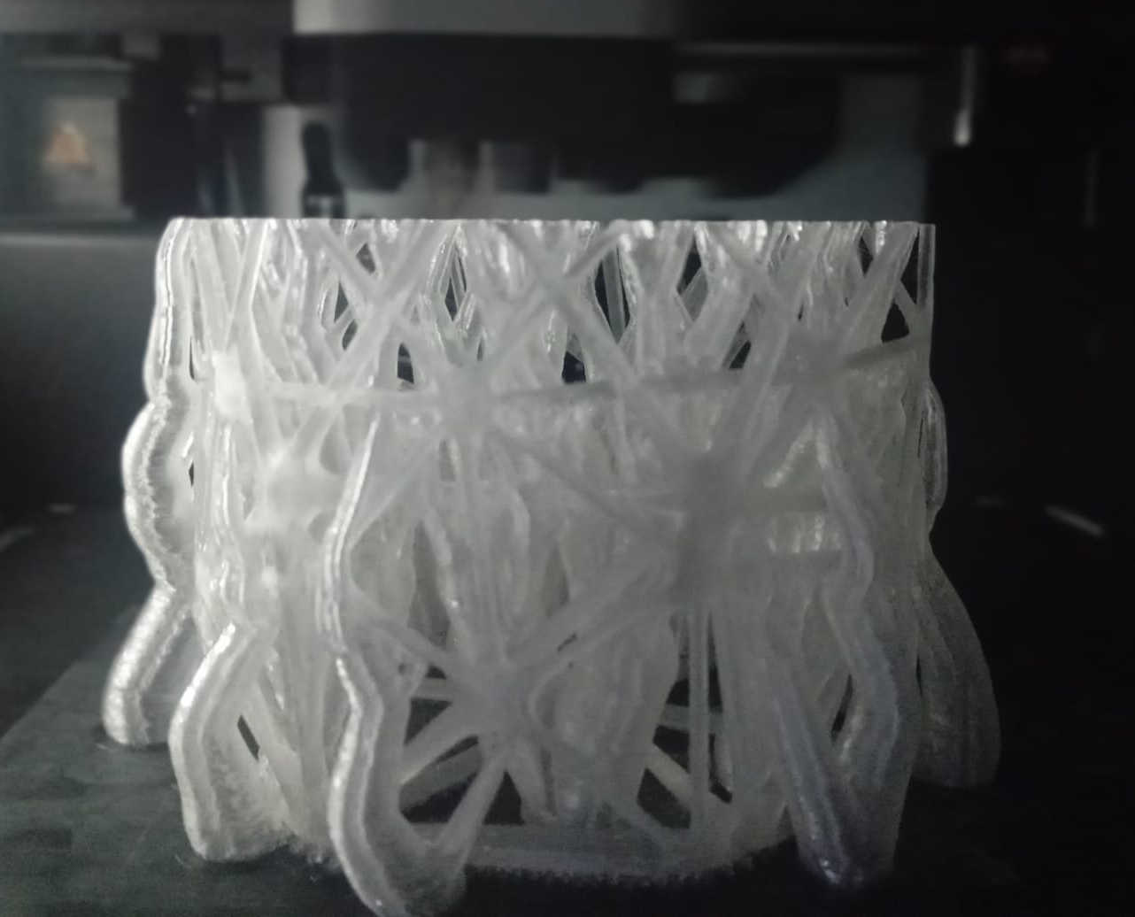
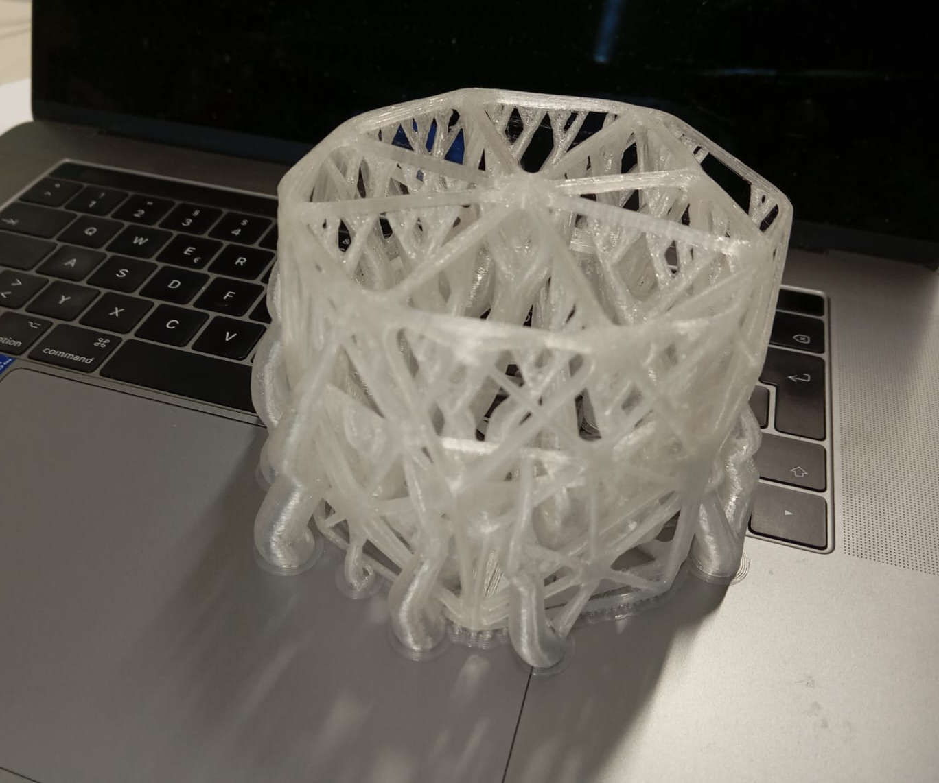
After a good 45 minutes the part was cleaned up and all the supports where removed. Here couple of hero shot of the 3D Print that
may have pushed the limit of 3D Printing.
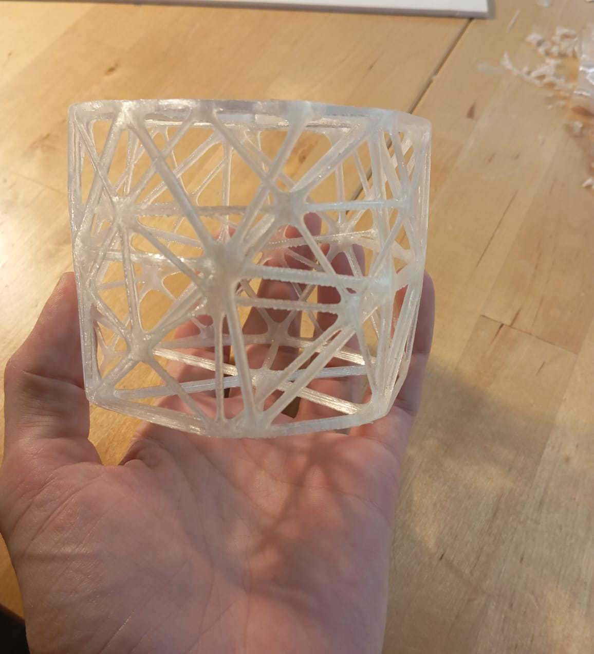
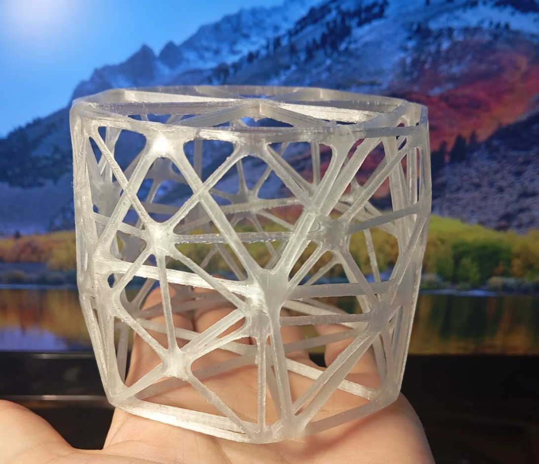
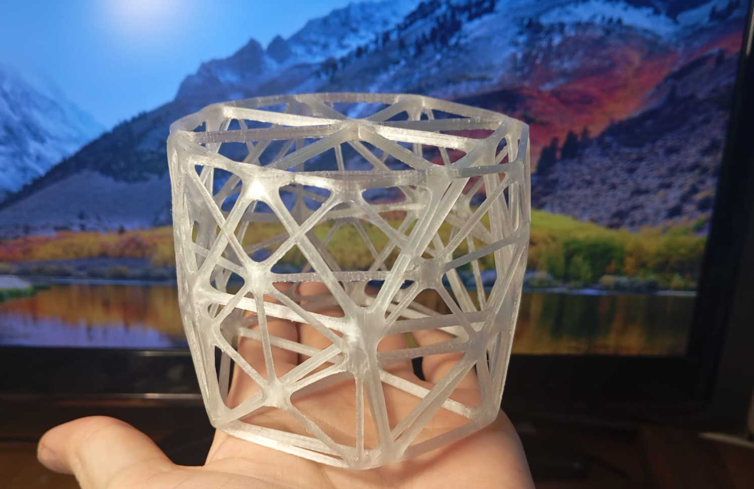
Click here to download the STL file.

3D scaning
Not really knowing why 3D scanning could be useful in any way, shape, or form, I spent a great deal of time researching its potential applications. One very good reason to scan something is to have a copy—this could even apply to important documents. But why 3D scan objects? The main definition of 3D scanning is the process of capturing the physical characteristics of an object or environment to convert it into a 3D model. This is a great tool for reverse engineering parts when the original files may no longer exist. A good example is scanning a motorcycle fairing, making it possible to recreate the same fairing with all of its features. This, in turn, allows for the creation of a CAD model that can be used to machine a mold on a CNC. 3D scanning can also be used to capture features and design parts that fit a model that may not have originally been designed for that machine or part. Another great application is quality control—using the scanned object to check for physical defects that may have occurred during production One of the most interesting functions of 3D scanning is in prosthetics. If someone loses a limb, the affected area can be scanned to help create a prosthetic limb that requires only minor adjustments for a perfect fit. 3D scanning can also play a role in preserving historical artifacts or even enabling virtual tours of sites like the pyramids without leaving the office or home. There are many more reasons why 3D scanning is useful. While it might seem like just a tool for fun, it has real applications across different industries.
3D scaning objects with the Shining 3D
One of this week's assignments was to 3D scan an object of our choice. I chose to have a flask scanned as it was small.
The first thing that needed to be done was to set everything up and calibrate the scanner. The scanner comes with multiple cabels that need to
be pluged in correctly. The scanner was also connect to a rotating table that is synced with the scanner over the the computers softwar.
Getting the scanner to calibrate took several tries as the scanner did not want to calibrate. After a couple of attempts, the calibration worked.
In theory, the calibration is fairly simple to do. You just follow the set of instructions that come with the program.
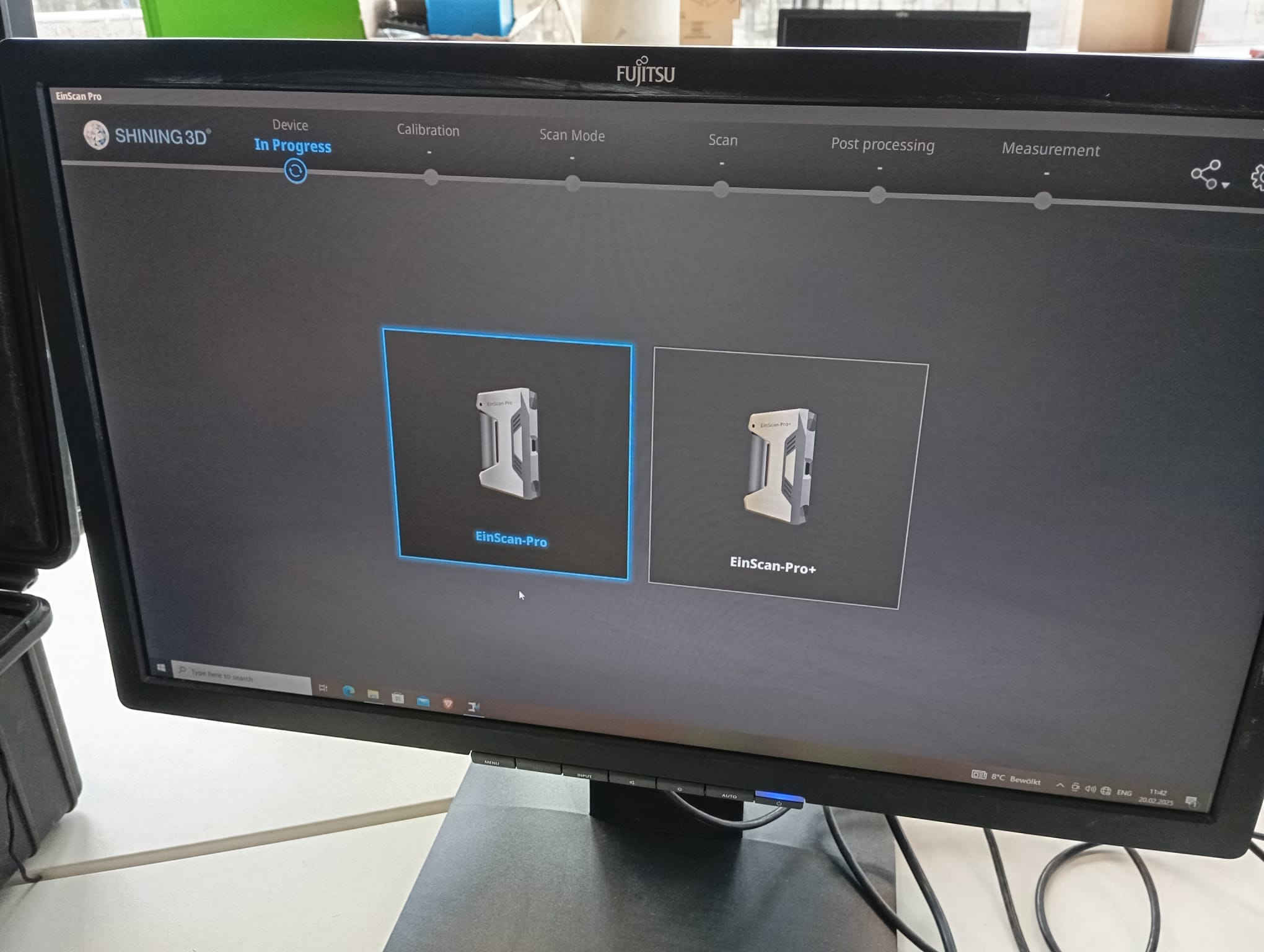
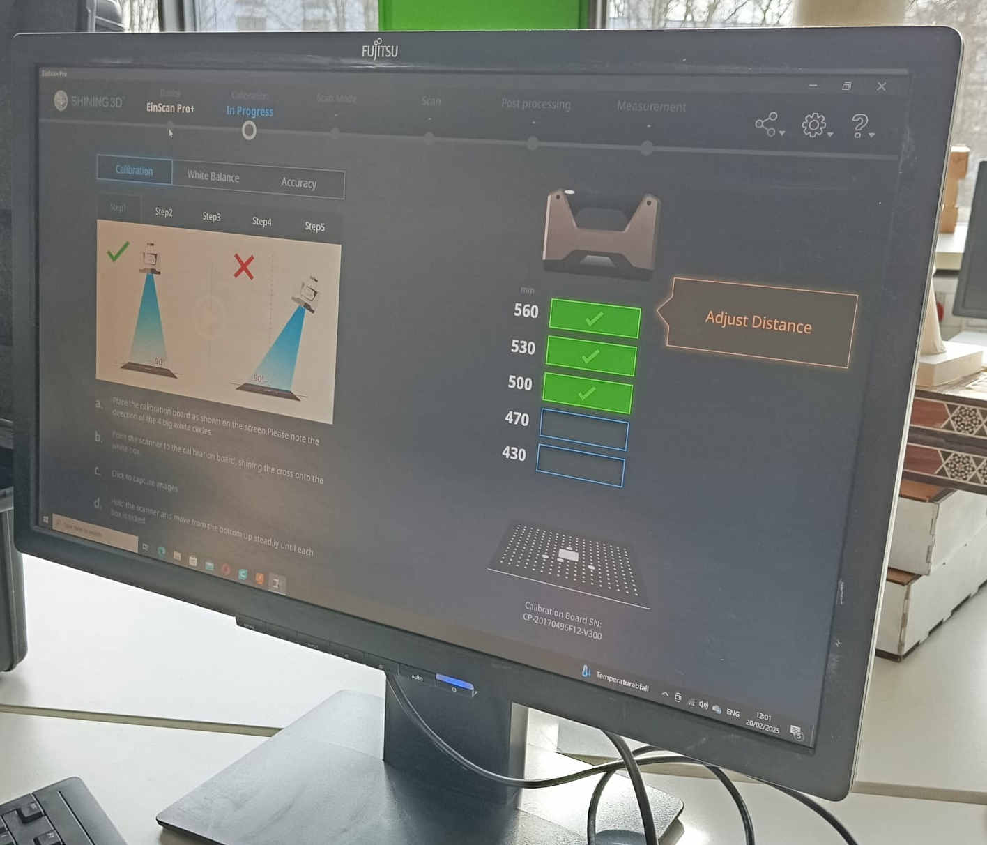
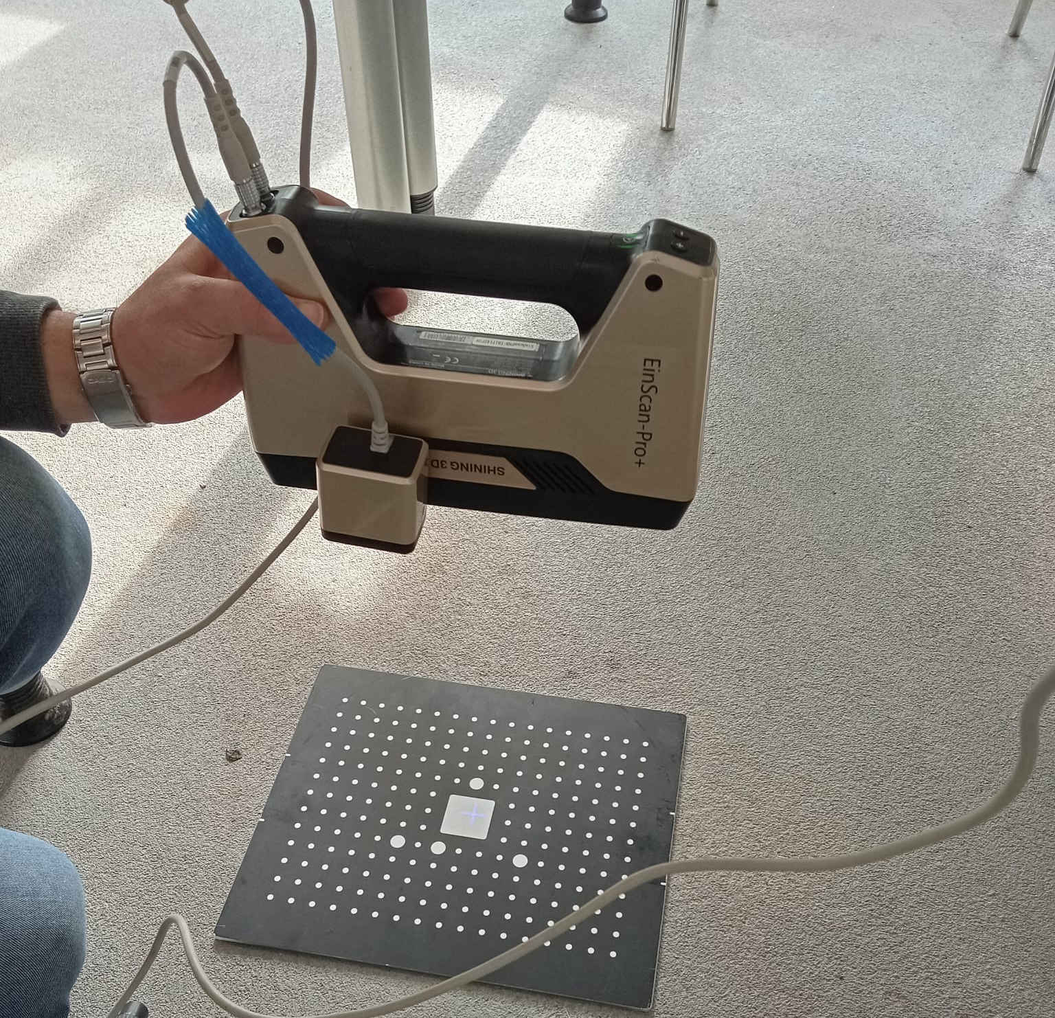
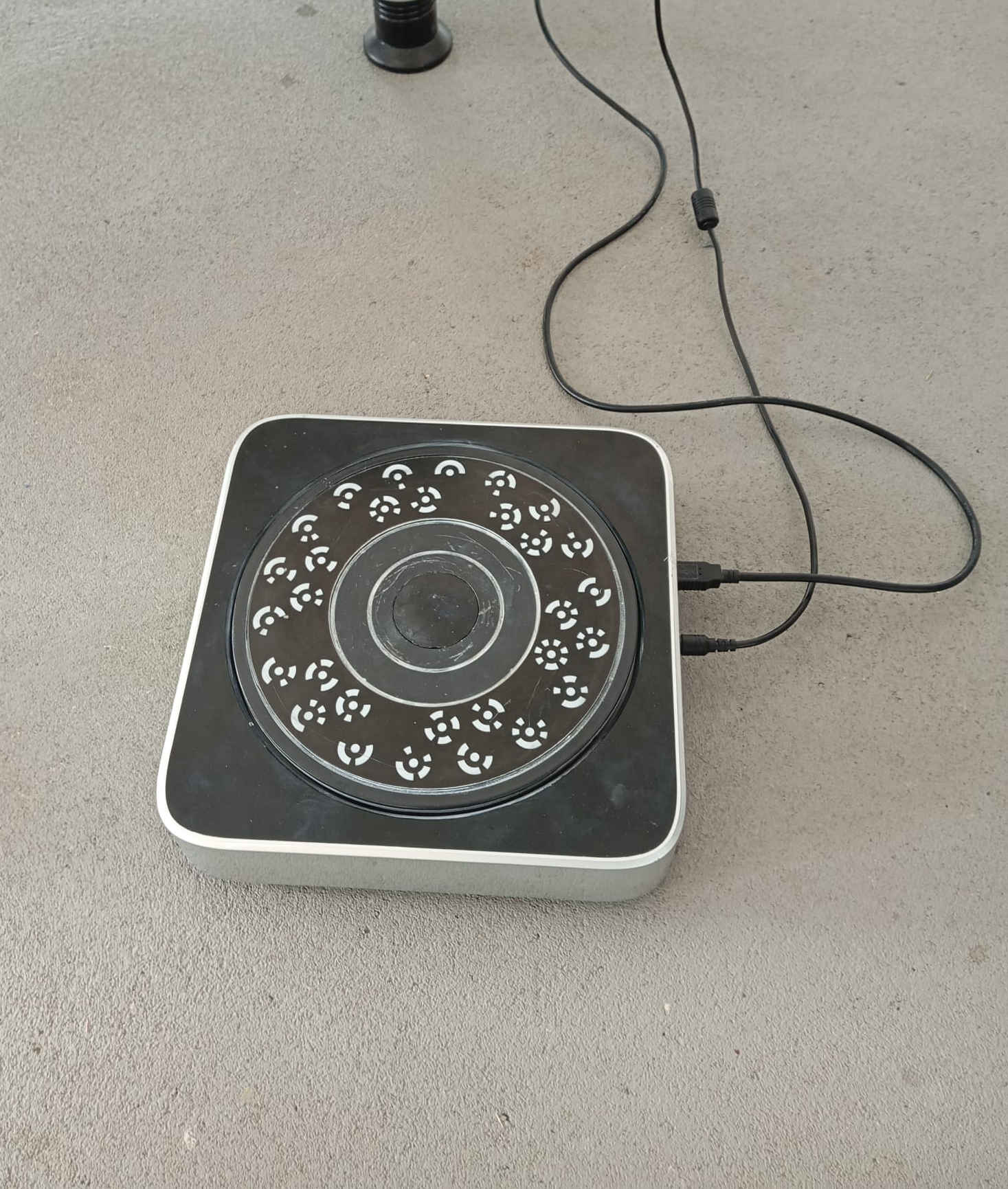
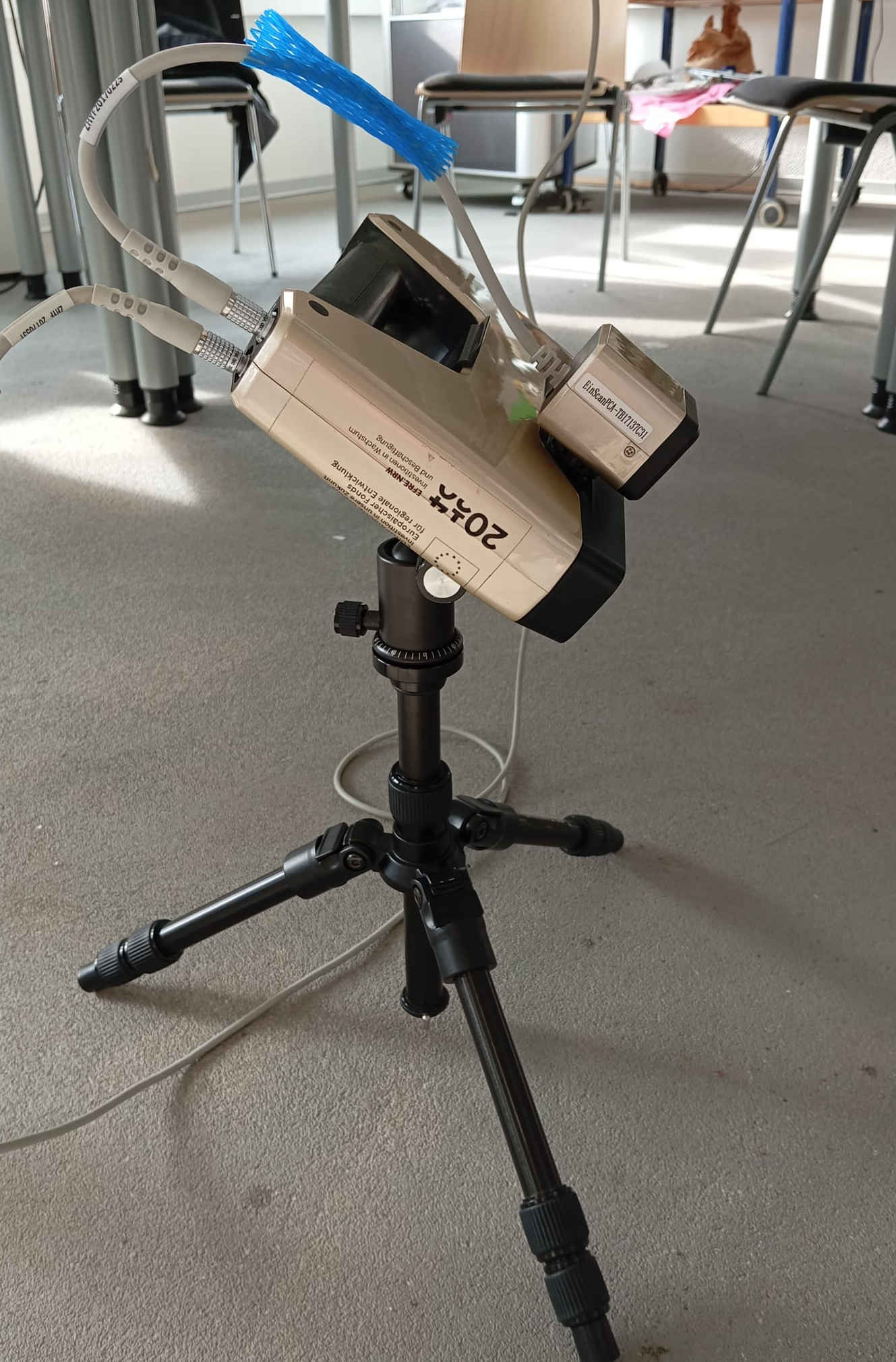
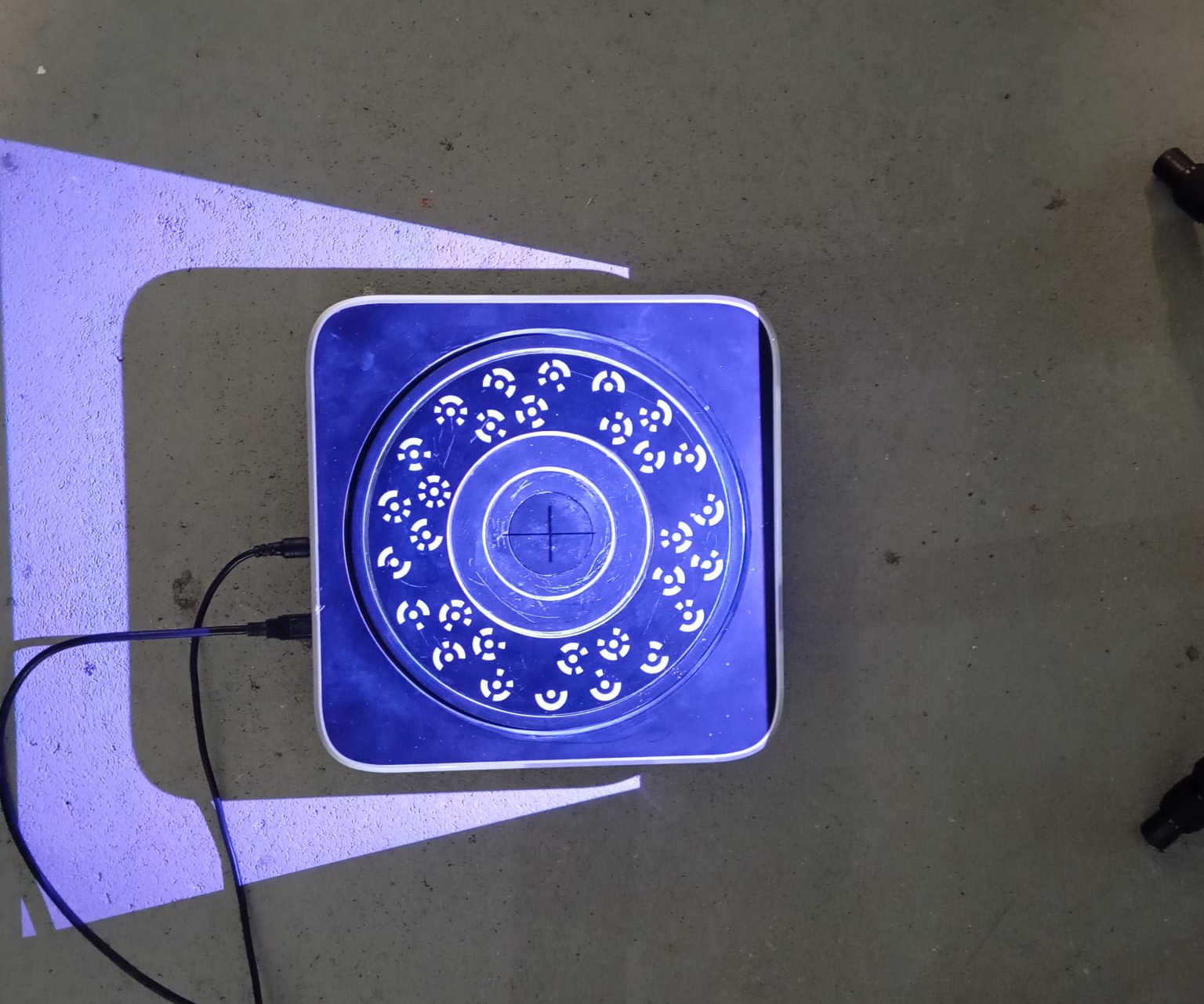
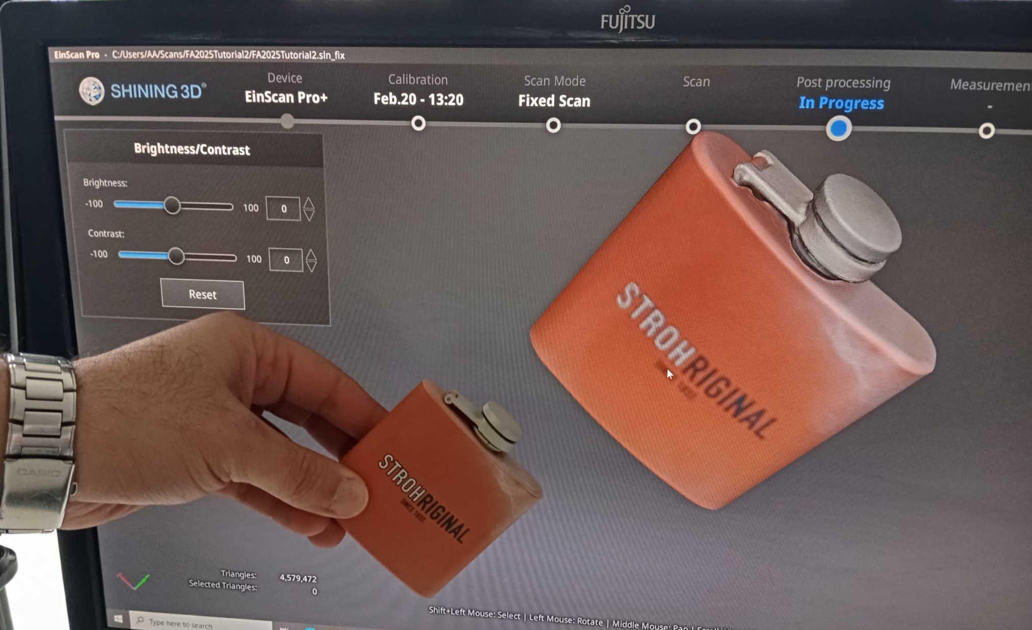
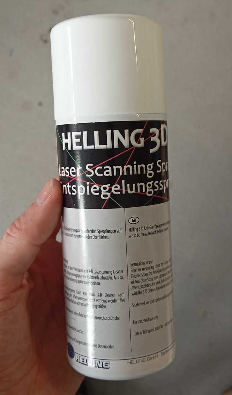
After having everything calibrated, the last thing to do was to adjust the rotating platform to the scanner, making sure that the projected cross was centered. An object or part could then be placed on the rotating platform. The next step was to select the number of pictures the scanner should take. The more images, the better the part can be scanned. It is important to note that scanners cannot scan objects with reflective surfaces. For this, a chalk-type spray can be applied to the object. This was the first attempt without the spray, which showed that reflective surfaces create problems when scanning.
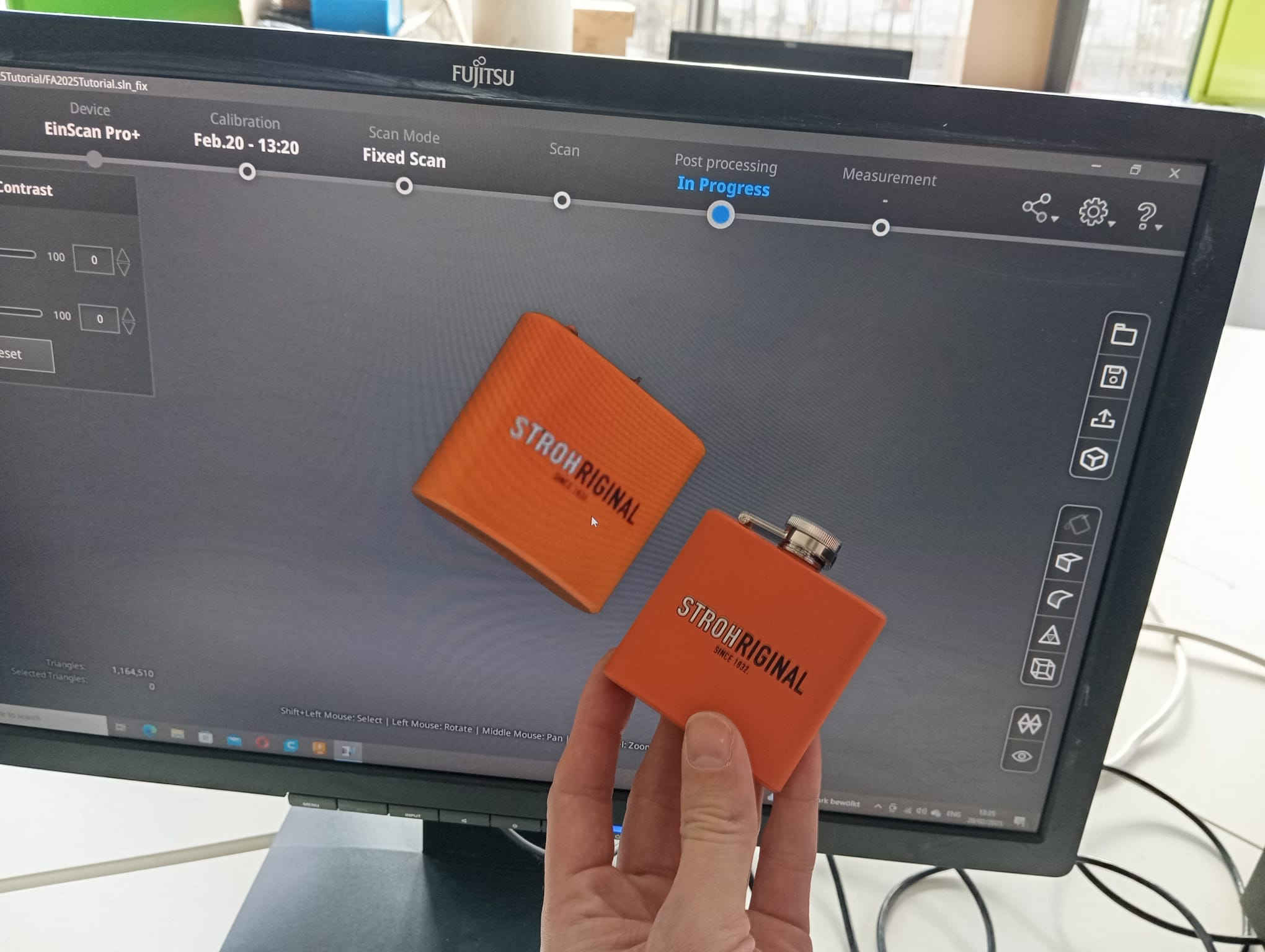
The scan turned out great, with color as well as the ability to read what was written on the flask. Next, the reflective surface was sprayed, which, depending on how much of the rest of the surface is sprayed, can take away a little of the color. Another thing to mention is that if part of the surface scan is missing, the algorithm in the meshing program will smooth it out. It is also possible to do multiple scans and mesh them into one image. When scanning the flask, the top surfaces were all scanned with the exception of the bottom. For this, the flask needed to be laid on its side, allowing the scanner to capture the bottom, which was then meshed with the first scans taken. Here are the results:
