13 - Moulding and Casting
Moulding and Casting with Silicone and 3D Prints
Moulding and casting using silicone and 3D prints is an efficient way to produce accurate, repeatable parts without needing complex tooling. The process starts with designing and printing a master mould, the original model that defines the final shape. Silicone is poured over the master to create a flexible mould that captures fine details and allows easy release, even for complex geometries and undercuts. Once the silicone cures, the mould can be used to cast a variety of materials, like polyurethane resin, epoxy, wax, or flexible rubbers, depending on the application. This method is ideal for prototyping, small-scale production, and replicating detailed parts where traditional manufacturing would be too expensive or slow.
How to get started
The first thing that we need to do is create a part in CAD. In this example Fusion 360 is being used. There are some things like draft angles that are used as they help with releasing the part from the mould. These range typically around the 1° to 5° Deg angle. With silicone moulds you can typically get away with undercuts, straight walls and sharp conners, but there could be some tearing. Another part to think give thought about is the surface finish of the mould, especially with 3D printed moulds. Silicone will capture all the details and transfer them to the cast laster. To avoid this you can do post processing on the 3D printed mould before you cast the silicone mould. This mainly depends on the surface roughness and surface finish you would want. It can also depend on the part itself. Most parts like a piston rod will get resurfaced after casting. There the post processing is done after the part has be cast and cured. This is done for two different reasons, one is tolerances can vary from the mold and the cast. The other is just to give the part a higher quality look.
In this weeks group assignment week 14, we also go over Health & Safety. depending on the type of Silicone, resin, or epoxy that is being used, you should always read the data sheet.This helps you clarify if a product can be harmful or dangerous. If you are unsure of the information given on the data sheet at the very least do this outside or in a very well ventilated room with fume extraction. Here I would also recommend that you wear gloves and old clothing as this is a messy and sticky work flow. Another reason to have a look at the data sheet is to find out what the ratio of the mix is, working time and curing time.
designing the part for the mould
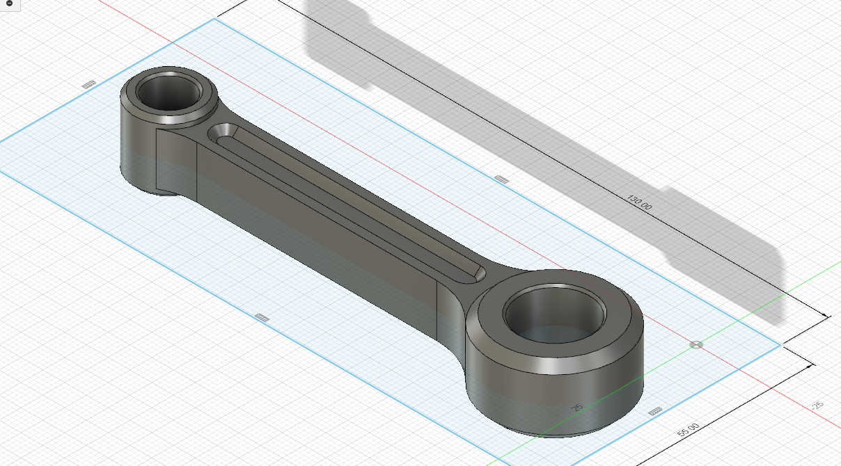
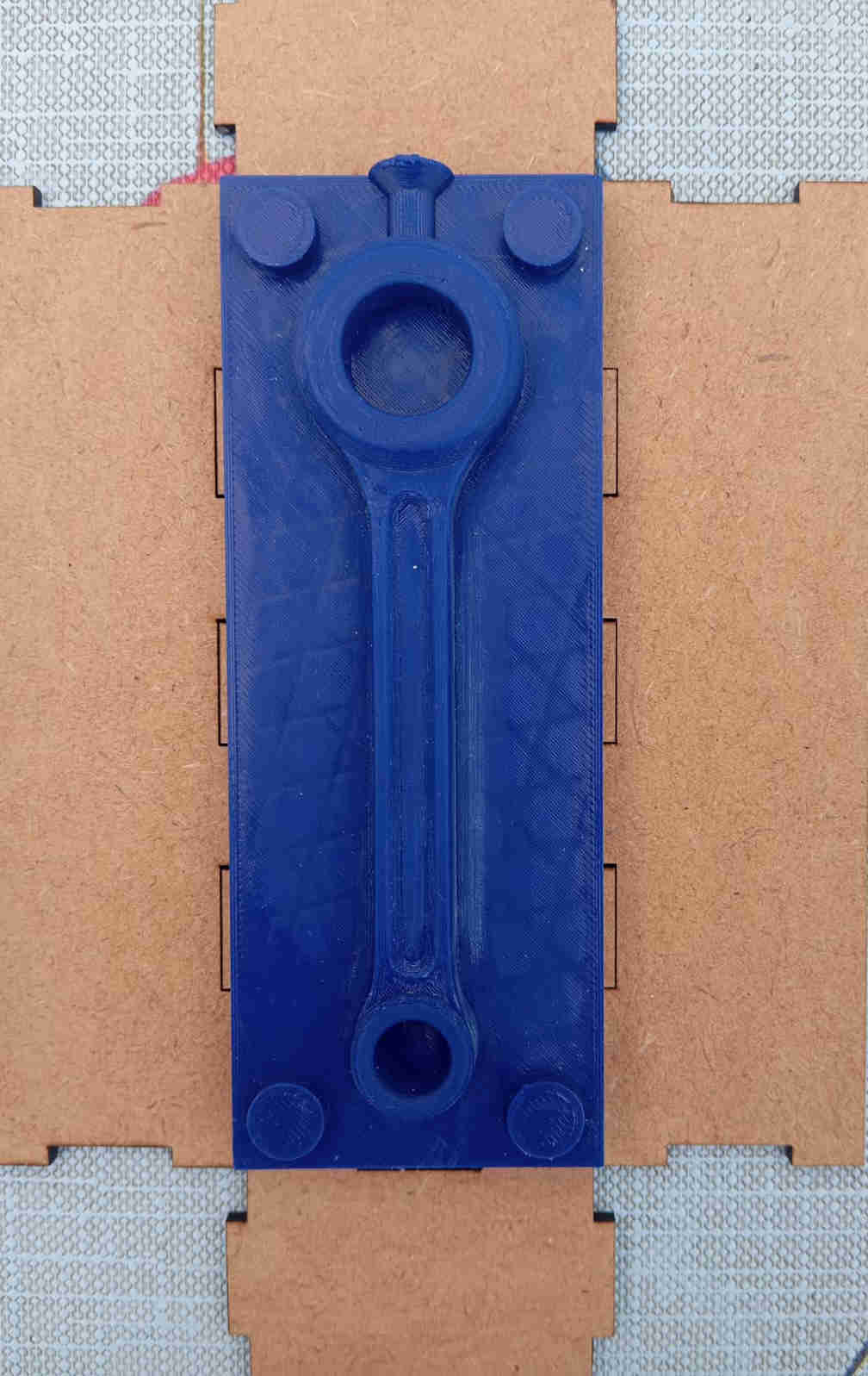
To design a mould you first need to create the part that you want to cast in the mould itself. I did start out of thinking about making a complete chess set, time was a bit of an issue this week, after talking to some one I know who really knows mould design I made the decision to learn how to create a part that has the features of a real metal casting mould. The best example of such a product that very one has at least seen or heard of is a piston rod.
The piston rode for the mould
Forging vs. Casting
Forging and casting are two totally different ways to shape metal, and each one has its place. Casting is when you melt metal down and pour it into a mould, which makes it easier to create complex shapes. It’s cheaper for mass production, but the downside is that the metal cools with a random grain structure and might have tiny defects like air pockets. That makes it weaker overall. Forging is kind of the opposite, you heat the metal until it’s soft, then smash it into shape with serious pressure. That compresses and aligns the grain structure, so forged parts are way stronger and more durable, especially under stress. The tradeoff is that you’re more limited in shape and usually need to machine the part afterward. A good example is piston rods: cast rods are cheaper and fine for most engines, but forged rods are what you want if you're dealing with high power, high RPM, or any serious performance setup. Here is a link to a short video showing how a piston rod is being forged using a mould.
Part to mould
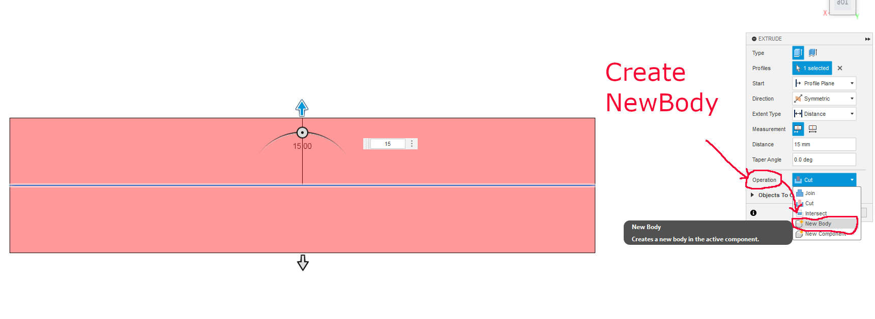
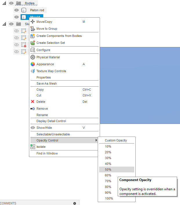
Once the you have the part has been design to satisfaction, create a mid-lane that is placed in the middle of the part. On this plane create sketch that out lines the part and extrude. You want to make sure that you have at a minium 10mm or more above the part. This helps the silicone in our case to be a little more rigid later on. When extruding, go to the pop up window and select Operation and select New Body. After the new body has been extruded, change the Component Opacity to 50%. This will allows you to see the part inside the new body part.
Changing the Opacity of the part right click on the new body under bodies.
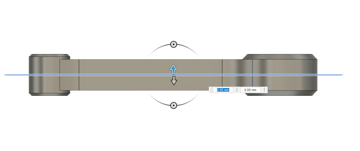
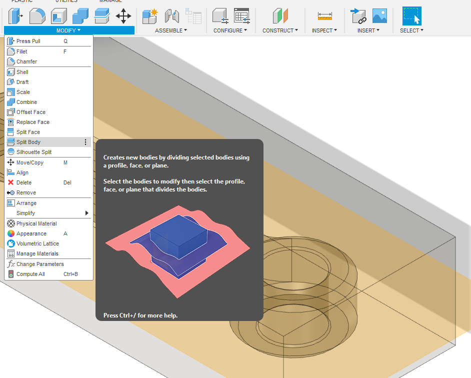
combining
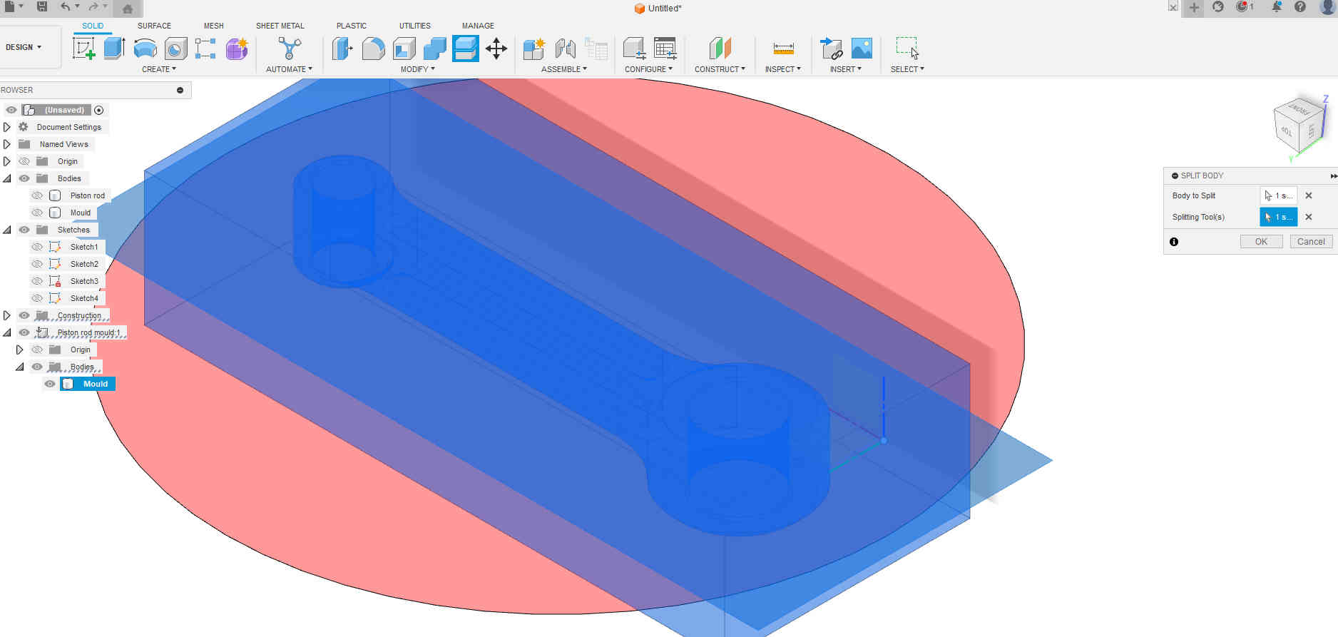
Next we want to combine the two bodies. Letting us subtracting one from the other. To do the we also need to add a new mid-plane, which will than allow the body to be split and subtracted from the other. First we combine and add the mid-Plane. Second step is to split where the mid selection of the plane is located. All of these functions are found in Modify menu.
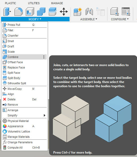
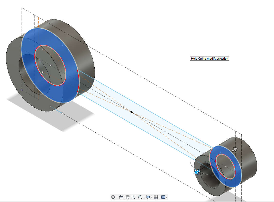
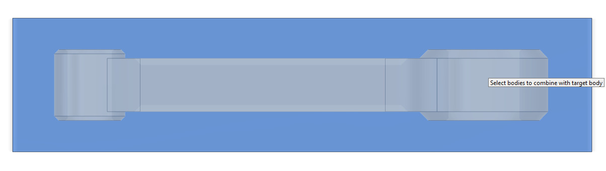
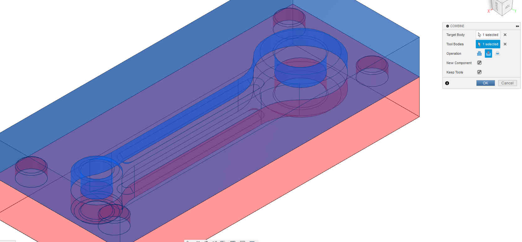
Now all that is left is to select the material that needs to removed and from the tooling body. In the Combine menu
Select the target and the tool bodies
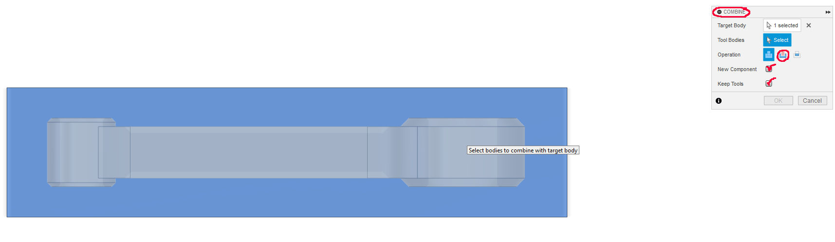
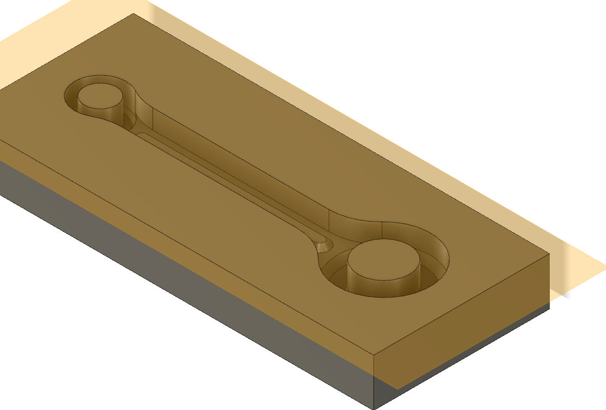
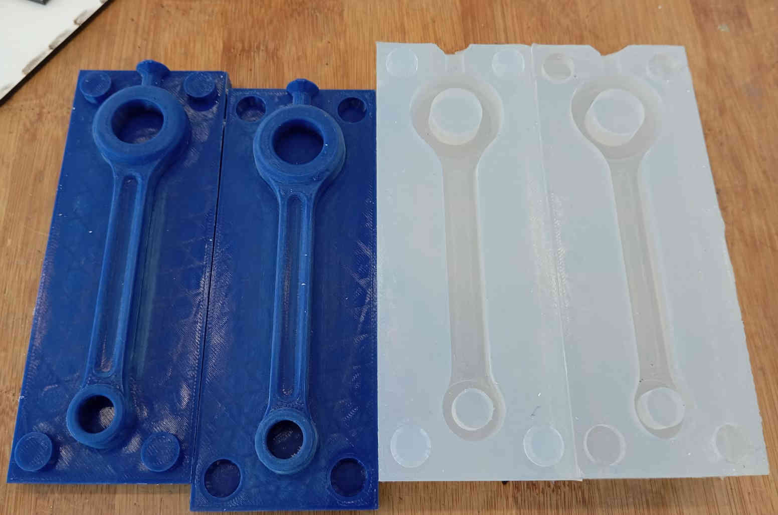
If everything was selected correctly, the result should look like this.
When hiding one side of the mould the result should show you a negative cavity of where the piston was located.
Important note here
I have show hwo to create a two part mold as how it is done in if you are going to manufacturing the mould by machining process. To cast a silicon mould you need to do the opposite. I ended up doing the same steps again to create a positive to create the negative to in silicon. Here you can split the part in two. Add a base and 3D or resin print the positive version. I took the long way around as I wanted to really learn about creating bodies and designing moulds. I will add both files to downloaded here.
Adding alignment points to the Mould
To keep the mould from sliding side to side and slipping during the casting process. A feature needs to be added. This can be anything that has a counter body shape. Here 4 10mm diameter locator pins were added. Each corresponding to the other second part of the mould. Very simple to do added 4 point to one side and used the Modify > Combine bodies function.
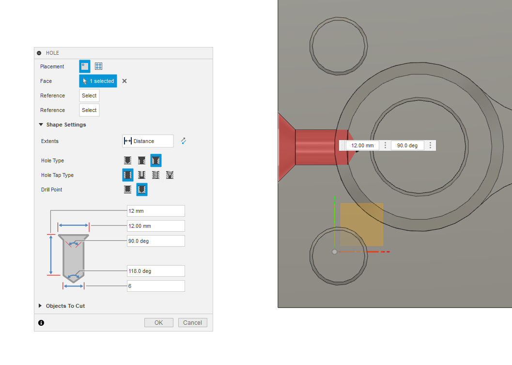
Next a spout top pour the resin or epoxy into is needed. I did not add the second spout having worked with resins and epoxies before. Depending on what material is being cast, it makes since to add the second spout for air to escape. It the resin cures slow there is not need to worry about air bubbles getting trapped. To add the spout I used the Hole function in Fusion and created the spout.
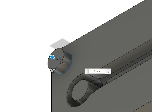
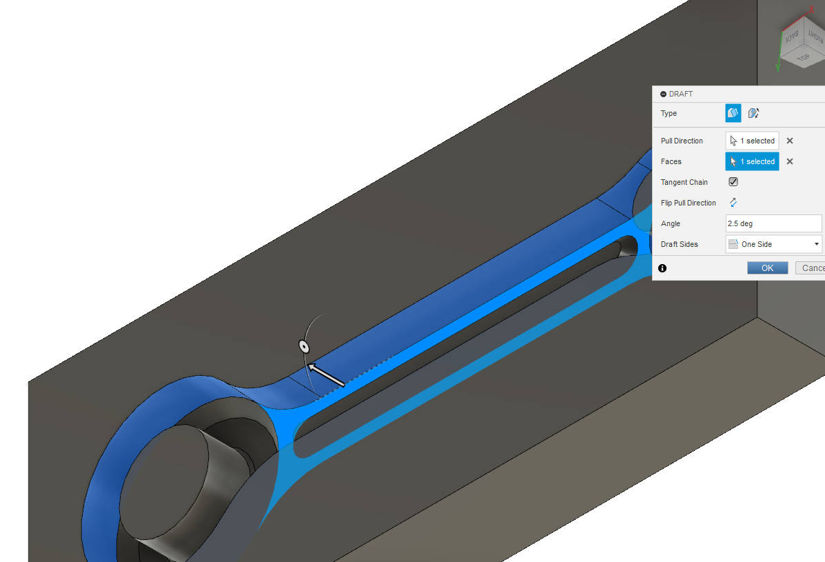
For the mould to release the part better a draft angle of 2.5° Degrees was added to the mould. This proved to be a true as I have not problem pulling out he part from the silicon and the also helped once removing the silicon mould from the positive 3D print.
Incase you missed the download files above, click downloaded here.
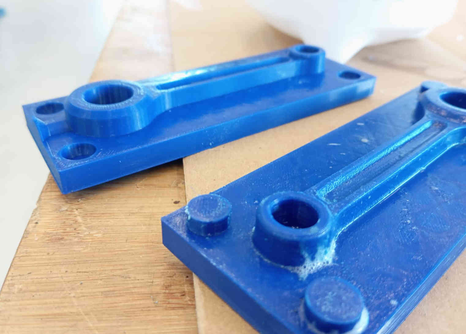
3D printing the positive mould & surfacing process
The next step in this process is the 3D Print the positive mould to make the negative mould. Here the mould was printed with a lever level of .2 for the finest result possible. Once positive mould was 3D printed, some light sanding with soupy water helped on hiding some of 3D printed edges. This is a processing to fix any mistakes or undesirable features can be removed, surfacing processing. This is not post processing as the part has not be made. Post processing is everything that happens after the casting is done. Depending on the material and the level of finish you’re going for, this can include trimming excess flash, sanding, polishing, painting, or even machining. With resin casting, you might need to clean up seam lines or bubbles, and for more precise parts, you’ll often end up drilling holes or adjusting surfaces to fit properly. If you 3D printed the mould or the master, layer lines can transfer into your cast, so sanding or priming the master ahead of time can save a lot of work later. The goal of post processing is to get the part looking and working exactly how you want it, whether that means functional accuracy or just a clean final look.
Casting Silicone
After the positive mould has been surfaced we went was a group and were shown how to mix the two components for casting the
the Silicone. Here have a look at our group assignment were we describe the process in more detail.
First step is to read the data sheet, and look for harmful chemical warnings. Secondly look for mixing ratio and working time. Once the right ratios have been
added to each other, we use a degassing chamber. This helps remove any and every air bubble that was introduced in pouring the mixes.
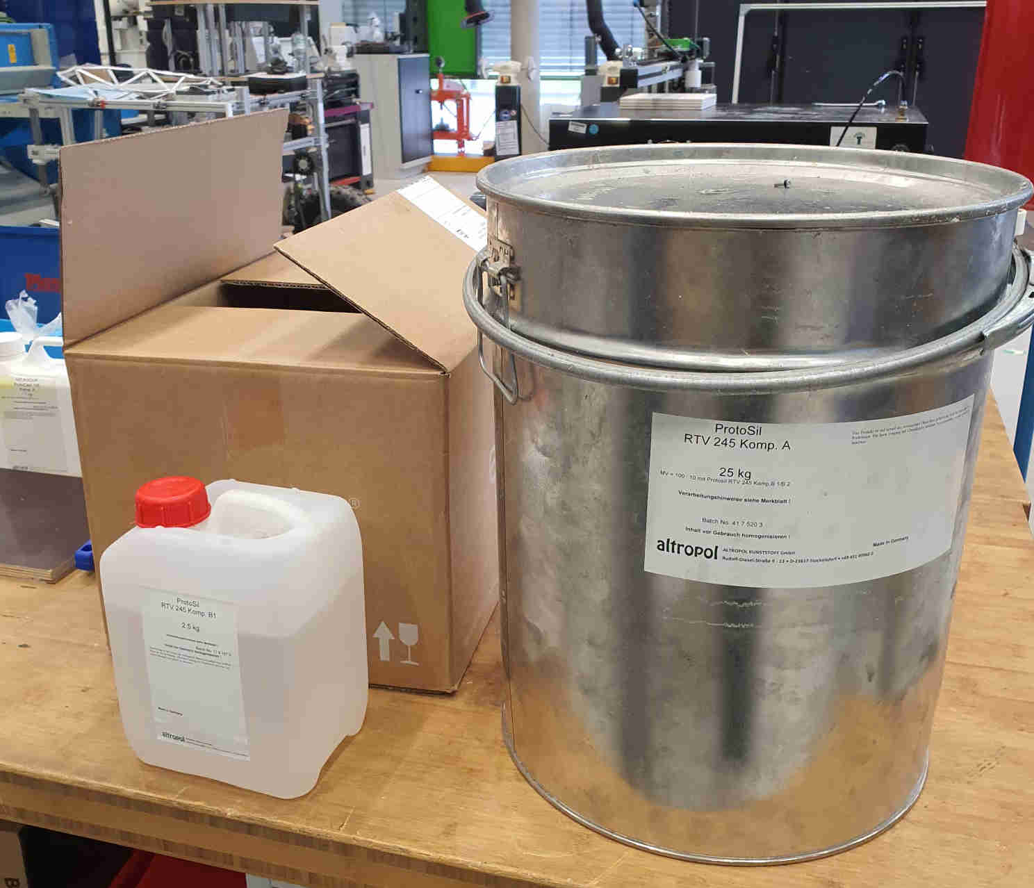
The Silicone we used was ProtoSil RTV 245 Komp. A and ProtoSil RTV 245 Komp. B and has a ratio of
100:10
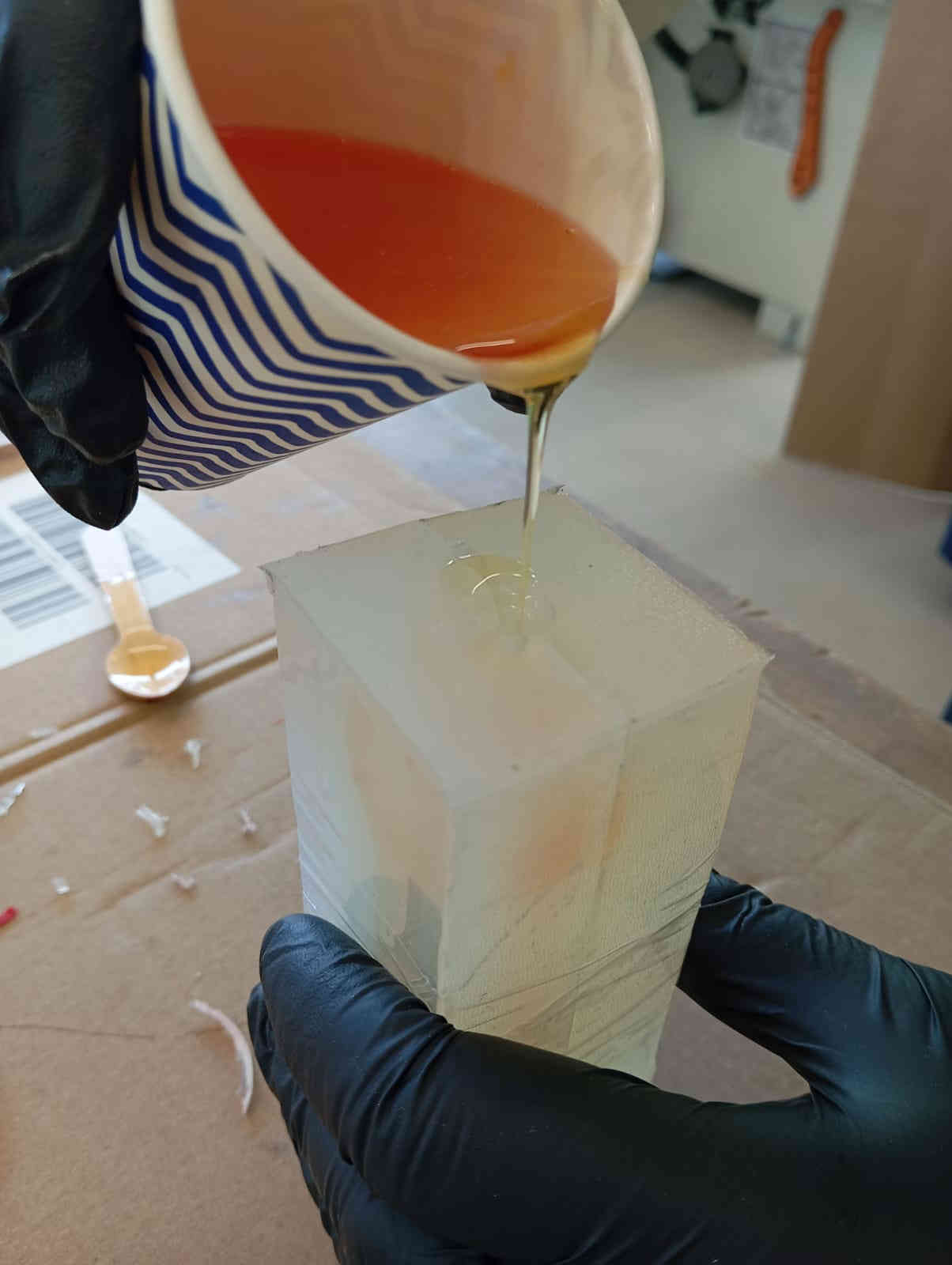
Pouring the mould
When pouring silicone as it has a thick viscosity you want to pour very fine feature of the positive mould first. This will helped
keep air bubbles to a minium. The silicone used in this case has a working time of 12 hours which helps with the minimizing bubbles,
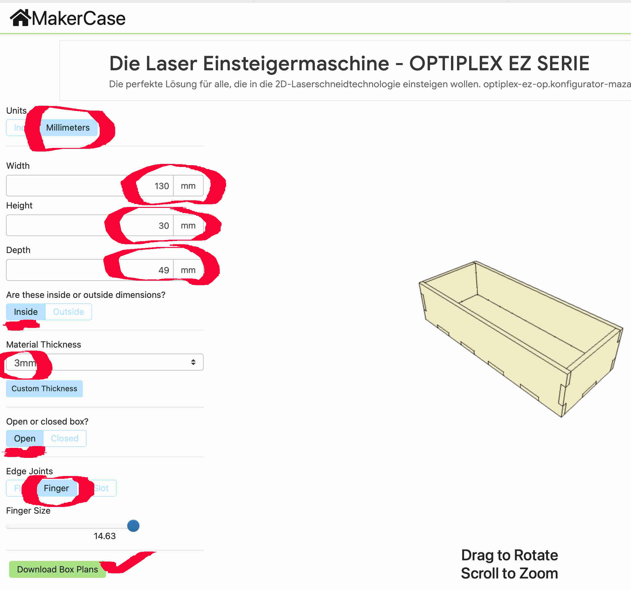
giving the trapped air time to escape. I also used he webpage called makercase to make the outside of the
mould. It creates a box to your needs by entering the Hight, Width, and Length. You may also wan to check the box for finger joints. This helps with the
alignment of the box later. Simply download the DXF file. once the file was downloaded
I popped over to the laser cutter.
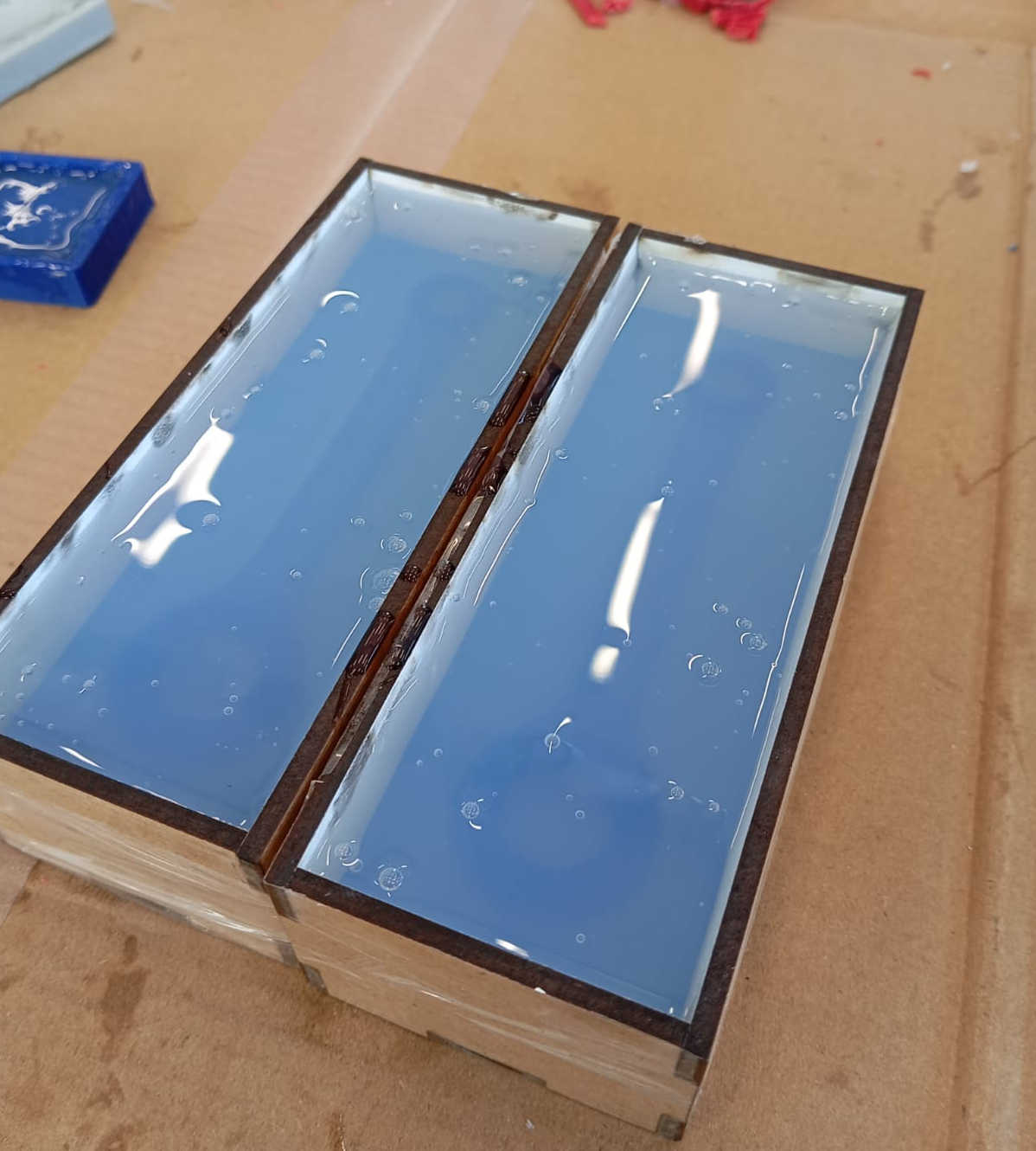
Now all that was left was to place everything together. I used some packing tape to hold the box's parts in place. Also it helped to keep any leaks from happening while the Silicone was curing.
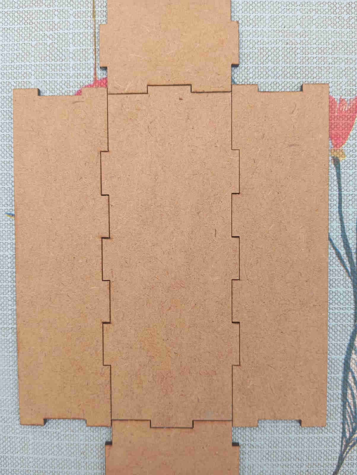
Here is the result after adding tape. Small tip is try not to use MDF as it can fuse to the silicone. In my case the other side was coated with melamine
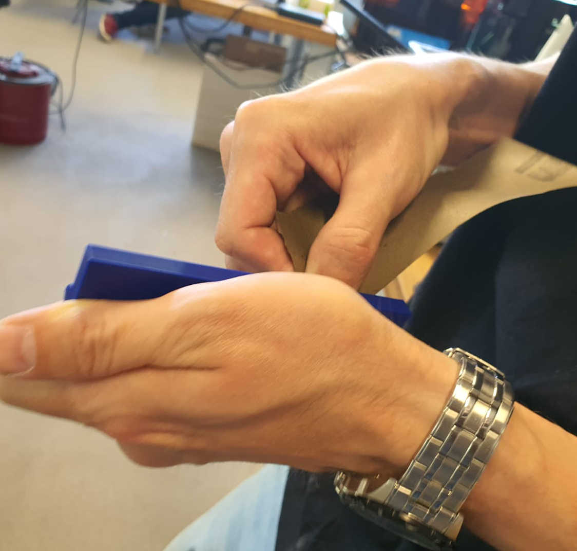
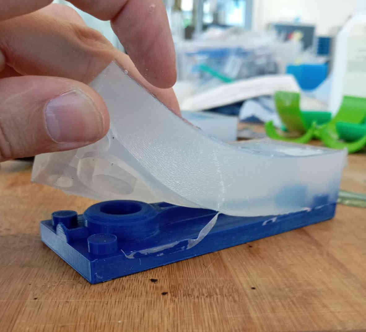
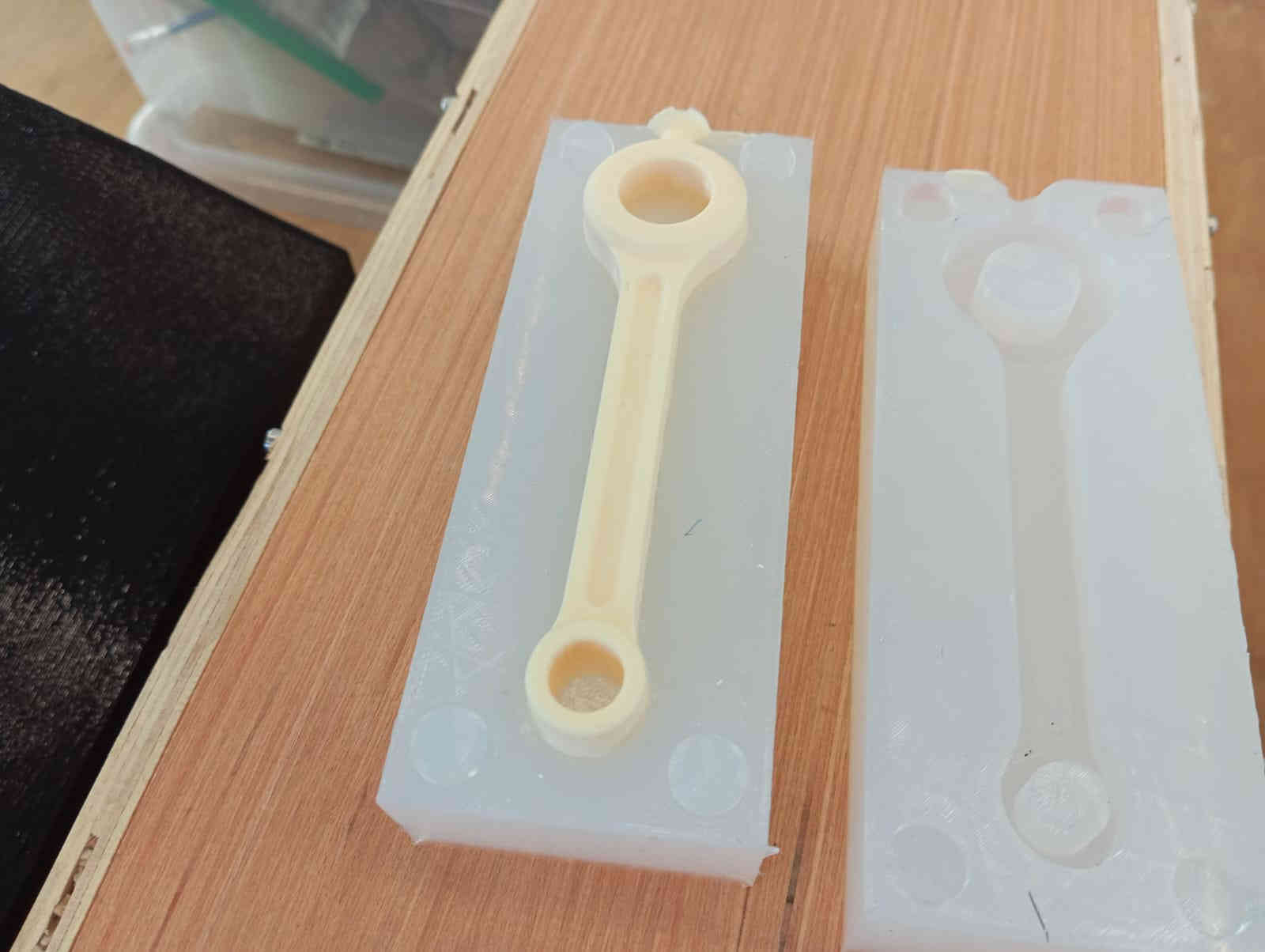
Removing the mold from the 3D print
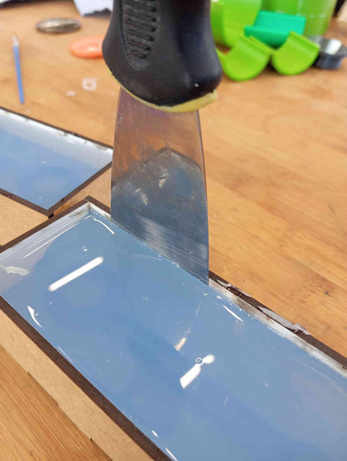
After seeing how much of a struggle everyone was having, I was a little worried that I may have the same issue. Turns out that this was not the case. I had added draft angles and had no undercuts or sharp angles. So I was really surprised, with how much ease the silicone was to remove. I used tha poddy knife to help relief the silicone from the melamine and from there it was a breeze.
Casting the part
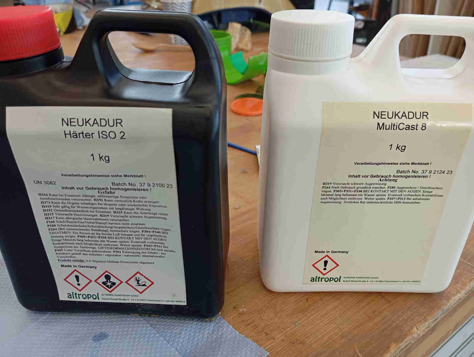
Here Mika and I decide that try a different resin called NEUKDAUR MultiCast 8. The mix was 1:1. This resin hardened so fast that as we where pouring, it turned solid. When using NEUKDAUR MultiCast 8, I would recommend knowing how much resin is needed and only mixing a little more than you would need to your cast. You should also consider having a degassing chamber when using this resin as there is no time for air to escape in the about of time that NEUKDAUR MultiCast 8 hardens. Also make sure you have a pouring cup that can take the thermal heat of the two part resin reaction as it can get really hot and may cause harm or even start burning! The cast went so fast that after 10 mins I was able to remove the cast.
Post processing
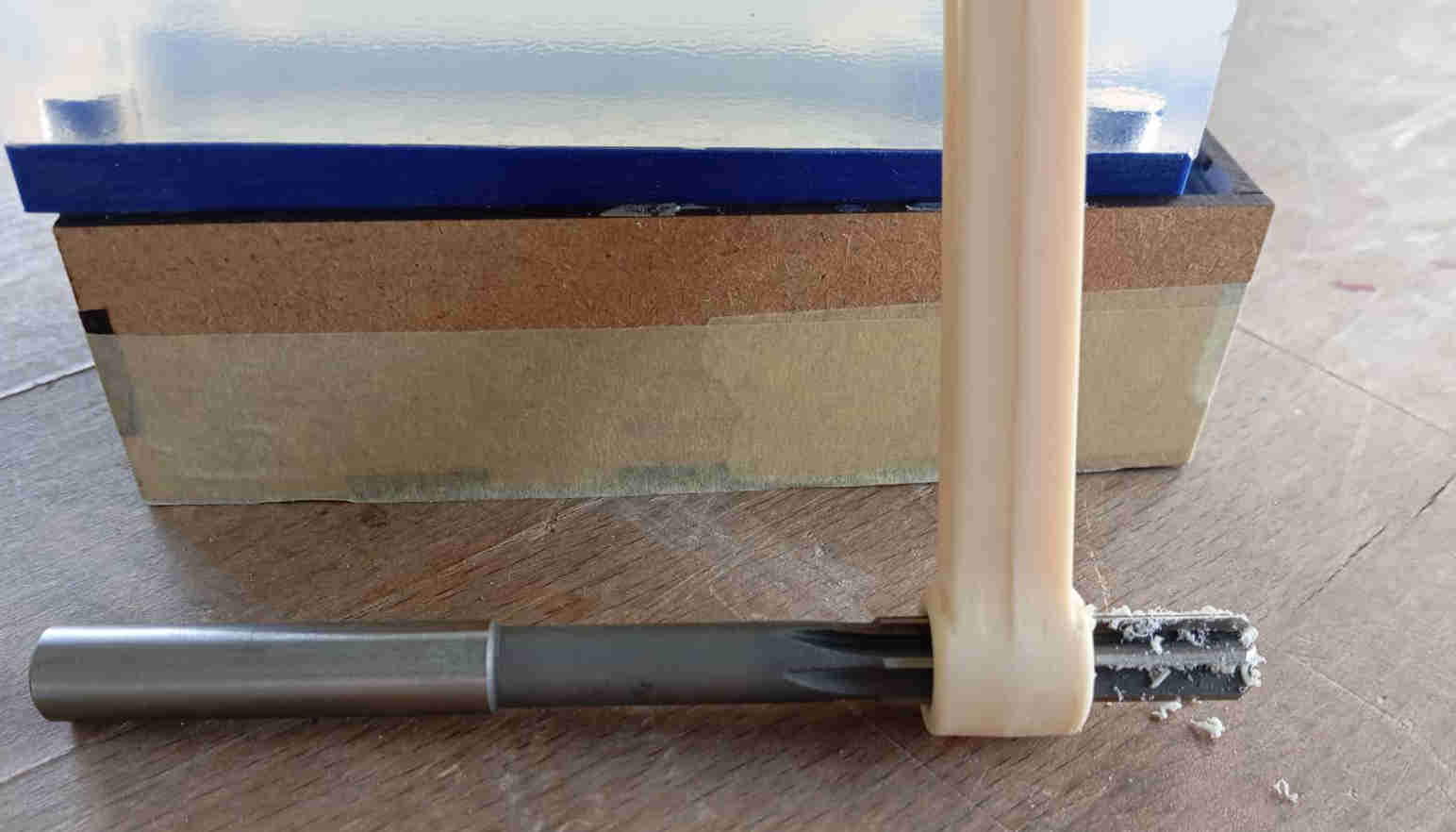
Even though the part came out they I expected it, the piston Rod was designed so that some Post processing is needed, just as it is done with a real piston rod. The rods holes needed to be reamed co the right size. The reason for this was that the mould has a Draft angele of 2.5° Degrees meaning that the holes are conical. The other part that needed to be addresses was the seam along the sides of the piston rod. Here I used some 200 grit sanding paper to lightly remove the seam along the part.
Finishing and Hero shots